EP3676474B1 - Fräswerkzeug - Google Patents
Fräswerkzeug Download PDFInfo
- Publication number
- EP3676474B1 EP3676474B1 EP18762011.7A EP18762011A EP3676474B1 EP 3676474 B1 EP3676474 B1 EP 3676474B1 EP 18762011 A EP18762011 A EP 18762011A EP 3676474 B1 EP3676474 B1 EP 3676474B1
- Authority
- EP
- European Patent Office
- Prior art keywords
- milling
- section
- milling tool
- metal cuttings
- magnetic element
- Prior art date
- Legal status (The legal status is an assumption and is not a legal conclusion. Google has not performed a legal analysis and makes no representation as to the accuracy of the status listed.)
- Active
Links
Images


Classifications
-
- E—FIXED CONSTRUCTIONS
- E21—EARTH OR ROCK DRILLING; MINING
- E21B—EARTH OR ROCK DRILLING; OBTAINING OIL, GAS, WATER, SOLUBLE OR MELTABLE MATERIALS OR A SLURRY OF MINERALS FROM WELLS
- E21B33/00—Sealing or packing boreholes or wells
- E21B33/10—Sealing or packing boreholes or wells in the borehole
- E21B33/13—Methods or devices for cementing, for plugging holes, crevices or the like
-
- E—FIXED CONSTRUCTIONS
- E21—EARTH OR ROCK DRILLING; MINING
- E21B—EARTH OR ROCK DRILLING; OBTAINING OIL, GAS, WATER, SOLUBLE OR MELTABLE MATERIALS OR A SLURRY OF MINERALS FROM WELLS
- E21B27/00—Containers for collecting or depositing substances in boreholes or wells, e.g. bailers, baskets or buckets for collecting mud or sand; Drill bits with means for collecting substances, e.g. valve drill bits
- E21B27/04—Containers for collecting or depositing substances in boreholes or wells, e.g. bailers, baskets or buckets for collecting mud or sand; Drill bits with means for collecting substances, e.g. valve drill bits where the collecting or depositing means include helical conveying means
-
- E—FIXED CONSTRUCTIONS
- E21—EARTH OR ROCK DRILLING; MINING
- E21B—EARTH OR ROCK DRILLING; OBTAINING OIL, GAS, WATER, SOLUBLE OR MELTABLE MATERIALS OR A SLURRY OF MINERALS FROM WELLS
- E21B29/00—Cutting or destroying pipes, packers, plugs or wire lines, located in boreholes or wells, e.g. cutting of damaged pipes, of windows; Deforming of pipes in boreholes or wells; Reconditioning of well casings while in the ground
- E21B29/002—Cutting, e.g. milling, a pipe with a cutter rotating along the circumference of the pipe
- E21B29/007—Cutting, e.g. milling, a pipe with a cutter rotating along the circumference of the pipe with a radially-retracting cutter rotating outside the pipe
-
- E—FIXED CONSTRUCTIONS
- E21—EARTH OR ROCK DRILLING; MINING
- E21B—EARTH OR ROCK DRILLING; OBTAINING OIL, GAS, WATER, SOLUBLE OR MELTABLE MATERIALS OR A SLURRY OF MINERALS FROM WELLS
- E21B37/00—Methods or apparatus for cleaning boreholes or wells
- E21B37/02—Scrapers specially adapted therefor
Definitions
- the present invention relates to the field of milling tools, and more specifically to a milling tool, and a method of using said milling tool.
- P&A In a common plugging and abandonment operation (P&A), a section of the well casing(s) in a wellbore is milled away and a cement plug is subsequently set at said section to permanently seal off the well.
- the milling operation produces large amounts of metal cuttings which may interfere with both the milling operation itself and the subsequent plug cementing operation.
- P&A does not really require that the metal cuttings (often termed swarf) are removed from the wellbore after performing a milling/cutting operation, since a plugged and abandoned well does not contain any well equipment, such as a Blow-Out Preventer (BOP), that may be damaged by the presence of metal cuttings.
- BOP Blow-Out Preventer
- US 6679328 B2 discloses a milling tool for milling a section of casing. The milling is performed while pulling the milling tool in an upward direction by use of a hydraulic thrusting mechanism. The produced metal cuttings are moved downwards into the wellbore by use of a spiral auger.
- WO 2010/120180 A1 discloses a milling tool for milling a section of casing. The milling is performed while pulling the milling tool in an upward direction presumably by use of a drill pipe. The produced metal cuttings are moved downwards into the wellbore by use of a fluid conduit and optionally a spiral auger.
- the present invention provides a milling tool, wherein at least some of the disadvantages of the prior art is alleviated or avoided.
- the present invention provides a milling tool for a wellbore as set out in claim 1 of the appended claims.
- the rotation generating device can be connected to the helix-shaped longitudinal guide element.
- the cylinder-shaped magnetic element can be rigidly connected to the milling section, such that the magnetic element co-rotates with the milling section.
- the helix-shaped longitudinal guide element can be made in a suitable non-magnetic material.
- the milling section can be rotatable relative to the wellbore, preferably by a connected well string or drill pipe.
- the milling section can be rotated by a second rotation generating device, such as any suitable type of hydraulic or electric motor.
- the metal cuttings removal section can be configured such that metal cuttings accumulating on the cylinder-shaped magnetic element during use are pushed away from the milling tool, and preferably further down into the well bore.
- the metal cuttings removal section can be configured such that metal cuttings accumulating on the cylinder-shaped magnetic element during use is pushed away from the milling section.
- the milling section can comprise multiple nozzles for drilling mud, or drilling mud nozzles, the outlet of the nozzles being arranged such that metal cuttings formed/produced during a milling operation are guided towards the metal cuttings removal section during use.
- the nozzles are arranged to eject drilling mud in the downwards direction of the well bore.
- the drilling mud flow from the nozzles can contribute to push the metal cuttings down into the wellbore.
- the multiple nozzles are preferably radially arranged at the circumference of the milling section.
- the milling tool can comprise a central passage, e.g. a fluid conduit along the centerline of the tool, for supply of drilling mud to the drilling mud nozzles, for moving the cutters into the activated position, and/or for driving the rotation generating device.
- a central passage e.g. a fluid conduit along the centerline of the tool, for supply of drilling mud to the drilling mud nozzles, for moving the cutters into the activated position, and/or for driving the rotation generating device.
- an end section of the scrape can be arranged around a cylinder-shaped non-magnetic element.
- the non-magnetic element can extend a distance from the magnetic element, the distance being sufficient to eliminate the magnetic attraction between the metal cuttings and the cylinder-shaped magnetic element.
- the radially arranged milling elements can be multiple radially arranged cutters. Preferably three to eight cutters.
- the milling section can comprise a cylindrical housing in which the cutters are arranged. The cutters may be in a non-activated position, wherein the cutters are retracted in the housing or milling section, or an activated position, wherein the cutters are radially extended. In one embodiment, the cutters can be moved into the activated position by hydraulic pressure provided by drilling mud.
- the milling tool can be for use in plug and abandonment operations.
- the milling tool is a section mill for milling a radial section of all casing strings in a plug and abandonment operation.
- the milling section can be arranged at a level above the metal cuttings removal section.
- the rotation generating device can be a hydraulic motor, preferably a drilling mud operated motor, or a centralizing anti-torque element.
- the drilling mud operated motor can preferably be a roller vane motor.
- the centralizing anti-torque element can be connected to the helix-shaped longitudinal guide element and be able to interact with an inner surface of a wellbore, such that the helix-shaped longitudinal guide element is held substantially rotationally stationary relative the cylinder-shaped magnetic element when said magnetic element rotates along with the milling section.
- the rotation generating device can be a hydraulic or electric motor, preferably a drilling mud operated motor, arranged at the second end of the metal cuttings removal section and operatively connected to rotate the helix-shaped longitudinal guide element relative to the magnetic element.
- the milling section or the cuttings removal section can comprise a connecting end distal to the cuttings removal section or the milling section, respectively, the connecting end being suitable for connecting the tool to a wireline, a power cable, an umbilical, a well string, a drill pipe or a coiled tubing.
- the milling section can comprise a connecting end distal to the metal cuttings removal section, the connecting end being suitable for connecting the tool to a wireline, a power cable, an umbilical, a well string, a drill pipe or a coiled tubing.
- the present invention provides a method of plugging and abandoning a well bore as set out in claim 9 of the appended claims.
- the method can comprise the steps of:
- metal cuttings is intended to mean any type of metal debris and particles, commonly termed “swarf' produced during a milling operation.
- milling elements are intended to mean any type of edged milling feature arrangeable on a milling tool for grinding/cutting junk, casings etc. present in a wellbore.
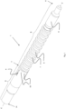
- a first embodiment of a milling tool according to the present invention is shown in figs. 1-4 .
- the inventive milling tool is particularly suitable for section milling in plug and abandonment operations (P&A).
- the milling tool according to the invention is able to perform milling while at the same time pushing/guiding produced metal cutting further down in the well bore.
- the present milling tool avoids or alleviates the interference of produced metal cuttings with the milling itself, i.e. the metal cuttings are prevented from nesting/clogging the cutters.
- the milling tool comprises a milling section 2 and a metal cuttings removal section 3.
- the milling section features four radially arranged cutters 4 (i.e. milling elements) suitable for milling a wellbore casing.
- the cutters may move between a passive and an active position. In the passive position, as shown in figs. 1-3 , the cutters are retracted into the milling section.
- the cutters are pretensioned into the passive position by a spring 11, and upon activation by drilling mud pressure via the passage 12, a piston assembly 18 will push the cutters radially outwards into an active position, in which the cutters are in contact with a wellbore casing to be cut and milled.
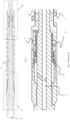
- the metal cuttings removal section 3 has a first end 5 and a second end 6 and comprises a cylinder-shaped magnetic element 7, a roller vane motor 8 (i.e. a rotation generating device) and a scraper 9 formed as a helix (i.e. a helix-shaped longitudinal guide element).
- the first end 5 is connected to the milling section.
- the scraper 9 is coaxially arranged around the cylinder-shaped magnetic element 7 and is operably connected to the roller vane motor 8.
- the roller vane motor 8 is driven by drilling mud entering the motor via the central longitudinal mud passage 12 and the mud inlets 13.
- roller vane motors suitable for use in a milling tool according to the invention are known and described in for instance WO 93/08374 , WO 94/16198 and US 6302666 B1 .
- any suitable type of hydraulic or electric motor may be used to rotate the scrape relative the magnetic element.
- the magnetic element 7 and the scraper 9 are rotatable relative to each other around a common centreline C, and configured such that metal cuttings accumulating on the magnetic element during use are guided by the scraper towards the second end 6 of the metal cuttings removal section 3 when the roller vane motor 8 is operated.
- a part 17 of the scrape 9 being proximal the second end 6 is arranged around a cylinder-shaped non-magnetic element 16 of the metal cuttings removal section.
- the scraper 9 is preferably made in non-magnetic stainless steel, e.g. a suitable type of austenitic stainless steel.
- the inner surface of the scrape i.e. the surface turned towards the circumferential surface of the magnetic element
- the inner surface of the scrape is slightly spaced (0.1-0.5 mm) from the circumferential surface. Further details, function and features of a suitable helix-shaped scrape and a corresponding magnetic element is disclosed in WO 2016/155852 A1 .
- the milling section 2 features a connecting end 14 distal from the metal cuttings removal section 3.
- the connecting end of the present embodiment is suitable for connecting the milling tool to a drill pipe (not shown).
- the drill pipe will provide the required rotation of the milling section 2, while at the same time providing mud to the roller vane motor 8 for rotating the scraper 9 relative the magnetic element 7, as well as a required hydraulic pressure for activation of the cutters 4.
- the milling section features multiple mud nozzles 10.
- the outlets of the nozzles are arranged in a direction such that the produced metal cuttings are moved towards the metal cuttings removal section during use.
- the mud exiting the nozzles are also advantageous in that it contributes to a more effective milling by guiding the metal cutting away from the cutters.
- FIG. 5 An exploded view of the metal cuttings removal section 3 of a second embodiment of a milling tool according to the invention is shown in fig. 5 .
- the second embodiment differs from the milling tool in figs. 1-4 in that the roller vane motor 8 is replaced by a centralizing anti-torque element 15 or anchor (i.e. an alternative rotation generating device) connected to the scraper 9.
- the anti-torque element 15 is radially extended to provide an adequate frictional contact with the inner surface of the wellbore/casing, such that the scraper 9 obtains a rotational movement relative to the magnetic element 7.
- the anti-torque element is only shown schematically, however detailed designs of suitable anti-torque elements would be obvious to the skilled person based on the present disclosure and the prior art.
- the anti-torque element 15 may for instance be similar to the anti-torque anchor devices disclosed in US 6679328 B2 or the gripper mechanism disclosed in WO 2015/112353 A1 .
- the centralizing anti-torque element 15 may for instance comprise radially extendable sections which are hydraulically activated by drilling mud via the central longitudinal mud passage 12.
- the milling tool according to the present invention is described in detail by reference to embodiments particularly suitable for section milling in connection with P&A operations, wherein the cuttings removal section is arranged to guide/push the produced metal cuttings further down into the wellbore.
- the main features of the inventive milling tool i.e. the combination of the milling section 2 and the metal cuttings removal section 3 will provide an advantageous effect in a number of different milling tools having different types of milling elements (including both retractable cutters and fixed cutters/blades), such as top mills, taper mills, junk mills etc. since the produced metal cuttings, and any other metal debris, are efficiently guided away from the milling section.
- This effect contributes to avoid clogging of metal debris at the site of milling and also to lower the wear of the milling elements.
- the advantageous effect is further increased by the feature of having nozzles 10 providing a drilling mud flow guiding the metal cuttings/debris away from the milling elements and towards the metal cuttings removal section.
Landscapes
- Geology (AREA)
- Life Sciences & Earth Sciences (AREA)
- Engineering & Computer Science (AREA)
- Mining & Mineral Resources (AREA)
- Environmental & Geological Engineering (AREA)
- Fluid Mechanics (AREA)
- Physics & Mathematics (AREA)
- General Life Sciences & Earth Sciences (AREA)
- Geochemistry & Mineralogy (AREA)
- Milling Processes (AREA)
- Earth Drilling (AREA)
- Drilling Tools (AREA)
- Magnetic Heads (AREA)
Claims (10)
- Fräswerkzeug (1) für ein Bohrloch, aufweisend einen Fräsabschnitt (2) und einen Abschnitt (3) zur Entfernung von Metallspänen, wobei- der Fräsabschnitt (2) radial angeordnete Fräselemente (4) aufweist, und- der Abschnitt (3) zur Entfernung von Metallspänen ein erstes Ende (5) und ein zweites Ende (6) aufweist, sowie ein zylinderförmiges magnetisches Element (7), eine rotationserzeugende Vorrichtung (8), und ein helixförmiges längliches Führungselement (9) aufweist, wobeiwobei∘ das erste Ende (5) mit dem Fräsabschnitt gekoppelt ist;∘ das helixförmige längliche Führungselement (9) um das zylinderförmige magnetische Element (7) herum angeordnet ist; und∘ die rotationserzeugende Vorrichtung (8) mit dem zylinderförmigen magnetischen Element (7) oder mit dem helixförmigen länglichen Führungselement (9) funktionsfähig gekoppelt ist; und
das eine aus dem zylinderförmigen magnetischen Element und dem helixförmigen länglichen Führungselement (9) in Bezug auf das andere um eine gemeinsame Mittellinie (C) rotierbar ist, und derart ausgebildet ist, dass Metallspäne, welche sich während des Betriebs auf dem zylinderförmigen magnetischen Element ansammeln, durch das helixförmige längliche Führungselement auf das zweite Ende (6) des Abschnittes zur Entfernung von Metallspänen hin geführt werden, wenn die rotationserzeugende Vorrichtung in Betrieb ist. - Fräswerkzeug gemäss Anspruch 1, wobei der Abschnitt (3) zur Entfernung von Metallspänen derart ausgebildet ist, dass Metallspäne, welche sich während des Betriebs auf dem zylinderförmigen magnetischen Element (7) ansammeln, vom Fräswerkzeug (1) weggeschoben werden.
- Fräswerkzeug gemäss einem der vorhergehenden Ansprüche, wobei der Fräsabschnitt mehrere Düsen (10) für Bohrspülung aufweist, wobei die Austritte der Düsen derart angeordnet sind, dass während des Betriebs Metallspäne zum Abschnitt (3) zur Entfernung von Metallspänen hingeführt werden.
- Fräswerkzeug gemäss einem der vorhergehenden Ansprüche, wobei ein Endabschnitt (17) des helixförmigen länglichen Führungselements (9) um ein zylinderförmiges nicht-magnetisches Element (16) herum angeordnet ist, wobei der Endabschnitt distal zum Fräsabschnitt (2) angeordnet ist.
- Fräswerkzeug gemäss einem der vorhergehenden Ansprüche, wobei es sich bei den radial angeordneten Fräselementen um mehrere radial angeordneten Cutter (4) handelt.
- Fräswerkzeug gemäss einem der vorhergehenden Ansprüche, wobei die eine Rotation erzeugende Vorrichtung (8) ein Hydraulikmotor ist, vorzugsweise ein durch Bohrspülung angetriebener Motor, oder ein zentralisierendes Drehmomentausgleichselement (15).
- Fräswerkzeug gemäss einem der vorhergehenden Ansprüche, wobei die rotationserzeugende Vorrichtung (8) ein durch Bohrspülung angetriebener Motor ist, welcher am zweiten Ende (6) des Abschnittes (3) zur Entfernung von Metallspänen angeordnet ist, und derart verbunden ist, um das helixförmige längliche Führungselement (9) in Bezug auf das magnetische Element (7) zu rotieren.
- Fräswerkzeug gemäss einem der vorhergehenden Ansprüche, wobei der Fräsabschnitt (2) oder der Abschnitt (3) zur Entfernung von Metallspänen ein verbindendes Ende (14) distal zum Abschnitt (3) zur Entfernung von Metallspänen bzw. zum Fräsabschnitt (2) aufweist, wobei das verbindende Ende (14) geeignet ist, das Fräswerkzeug (1) mit einer Drahtverbindung, einem Stromkabel, einem Nabelverbinder, einem Bohrstrang, einem Bohrrohr oder einer Rohrwendel zu verbinden.
- Verfahren zum Stopfen und zum Stilllegen eines Bohrlochs, beinhaltend die folgenden Schritte:- Herablassen eines Fräswerkzeugs (1) gemäss einem der Ansprüche 1-8 in das Bohrloch hinein; und- Fräsen eines radialen Abschnittes durch alle Gehäusestränge hindurch, welche sich während einer Bewegung des Fräswerkzeugs im Bohrloch befinden, unter gleichzeitigem Schieben von Metallspänen des Fräsvorgangs vom Fräswerkzeug weg und weiter hinab in das Bohrloch hinein.
- Verfahren gemäss Anspruch 9, ferner beinhaltend die folgenden Schritte:- Zurückholen des Fräswerkzeugs (2) an die Oberfläche; und- Ausführen der nötigen Arbeitsschritte zur Zementierung eines Pfropfens beim gefrästen radialen Abschnitt.
Applications Claiming Priority (2)
| Application Number | Priority Date | Filing Date | Title |
|---|---|---|---|
| NO20171418A NO343705B1 (en) | 2017-09-01 | 2017-09-01 | Milling tool |
| PCT/EP2018/070975 WO2019042699A1 (en) | 2017-09-01 | 2018-08-02 | GRINDING TOOL |
Publications (2)
| Publication Number | Publication Date |
|---|---|
| EP3676474A1 EP3676474A1 (de) | 2020-07-08 |
| EP3676474B1 true EP3676474B1 (de) | 2023-02-22 |
Family
ID=63407176
Family Applications (1)
| Application Number | Title | Priority Date | Filing Date |
|---|---|---|---|
| EP18762011.7A Active EP3676474B1 (de) | 2017-09-01 | 2018-08-02 | Fräswerkzeug |
Country Status (7)
| Country | Link |
|---|---|
| US (1) | US11371315B2 (de) |
| EP (1) | EP3676474B1 (de) |
| AU (1) | AU2018326158B2 (de) |
| DK (1) | DK3676474T3 (de) |
| EA (1) | EA202090561A1 (de) |
| NO (1) | NO343705B1 (de) |
| WO (1) | WO2019042699A1 (de) |
Families Citing this family (3)
| Publication number | Priority date | Publication date | Assignee | Title |
|---|---|---|---|---|
| NO343705B1 (en) * | 2017-09-01 | 2019-05-13 | Norse Oiltools As | Milling tool |
| CN110566149B (zh) * | 2019-10-15 | 2024-07-05 | 北京三叶西蒙科技有限公司 | 套铣一体化捞砂装置及其捞砂装置的使用方法 |
| US12024967B1 (en) | 2022-12-16 | 2024-07-02 | Halliburton Energy Services, Inc. | Method and apparatus to perform section milling |
Family Cites Families (22)
| Publication number | Priority date | Publication date | Assignee | Title |
|---|---|---|---|---|
| US5373900A (en) | 1988-04-15 | 1994-12-20 | Baker Hughes Incorporated | Downhole milling tool |
| EP0608316B1 (de) | 1991-10-18 | 1997-01-15 | ROE, John Richard Neville | Flügelverdrängungsmotor |
| US5224548A (en) * | 1991-12-26 | 1993-07-06 | Dankovich Ii Kalman E | Apparatus and method for retrieving lost materials in slanted boreholes |
| US5265675A (en) | 1992-03-25 | 1993-11-30 | Atlantic Richfield Company | Well conduit cutting and milling apparatus and method |
| EP0678151B1 (de) | 1993-01-07 | 1996-11-20 | Arnold Willem Josephus Prof.Ir. Grupping | Im bohrloch verwendeter rollenmotor und rollenpumpe |
| US6295716B1 (en) | 1994-10-28 | 2001-10-02 | American Superconductor Corporation | Production and processing of (Bi,Pb) SCCO superconductors |
| NL1007613C2 (nl) | 1997-10-21 | 1999-04-23 | Grup Ir Arnold Willem Josephus | Trillingsvrije rollenwiekmotor en rollenwiekpomp. |
| EP1165935A1 (de) * | 1999-03-30 | 2002-01-02 | French Oilfield Services Limited | Verfahren und vorrichtung zur reinigung von bohrlöchern |
| US6679328B2 (en) * | 1999-07-27 | 2004-01-20 | Baker Hughes Incorporated | Reverse section milling method and apparatus |
| GB0026460D0 (en) * | 2000-10-27 | 2000-12-13 | Sps Afos Internat Branch Ltd | Combined milling and scraping tool |
| US7137449B2 (en) * | 2004-06-10 | 2006-11-21 | M-I L.L.C. | Magnet arrangement and method for use on a downhole tool |
| GB0614990D0 (en) * | 2006-07-28 | 2006-09-06 | Rotary Drilling Supplies Europ | Device for collecting debris from a well |
| NO329613B1 (no) * | 2009-04-14 | 2010-11-22 | West Production Tech As | Anordning ved nedihullsapparat for maskinering av fôringsrør samt framgangsmåte for deponering av maskineringsspon |
| US20110284210A1 (en) * | 2010-05-18 | 2011-11-24 | Baker Hughes Incorporated | Dual-Pole Magnetic Attraction Downhole Magnetic Retrieval Apparatus |
| US9109417B2 (en) * | 2012-06-27 | 2015-08-18 | Odfjell Well Services Europe As | Drill string mountable wellbore cleanup apparatus and method |
| US9725977B2 (en) | 2012-10-04 | 2017-08-08 | Baker Hughes Incorporated | Retractable cutting and pulling tool with uphole milling capability |
| US9488020B2 (en) | 2014-01-27 | 2016-11-08 | Wwt North America Holdings, Inc. | Eccentric linkage gripper |
| DE112014007058T5 (de) | 2014-12-30 | 2017-07-20 | Halliburton Energy Services, Inc. | Bohrlochwerkzeugausräumerbaugruppe |
| DE102015205718A1 (de) | 2015-03-30 | 2016-10-06 | Continental Reifen Deutschland Gmbh | Fahrzeugluftreifen |
| NO20150391A1 (en) | 2015-03-31 | 2016-08-08 | Norse Oiltools As | Well cleaning tool and use of tool |
| GB2550053B (en) * | 2016-04-01 | 2020-12-09 | Romar International Ltd | Apparatus and method for removing magnetic particles from liquids or slurries from an oil or gas process |
| NO343705B1 (en) * | 2017-09-01 | 2019-05-13 | Norse Oiltools As | Milling tool |
-
2017
- 2017-09-01 NO NO20171418A patent/NO343705B1/en unknown
-
2018
- 2018-08-02 US US16/636,654 patent/US11371315B2/en active Active
- 2018-08-02 DK DK18762011.7T patent/DK3676474T3/da active
- 2018-08-02 EP EP18762011.7A patent/EP3676474B1/de active Active
- 2018-08-02 AU AU2018326158A patent/AU2018326158B2/en active Active
- 2018-08-02 EA EA202090561A patent/EA202090561A1/ru unknown
- 2018-08-02 WO PCT/EP2018/070975 patent/WO2019042699A1/en not_active Ceased
Also Published As
| Publication number | Publication date |
|---|---|
| WO2019042699A1 (en) | 2019-03-07 |
| US20210148189A1 (en) | 2021-05-20 |
| DK3676474T3 (en) | 2023-05-30 |
| US11371315B2 (en) | 2022-06-28 |
| EP3676474A1 (de) | 2020-07-08 |
| BR112020004033A2 (pt) | 2020-09-01 |
| EA202090561A1 (ru) | 2020-07-15 |
| NO20171418A1 (en) | 2019-03-04 |
| NO343705B1 (en) | 2019-05-13 |
| AU2018326158A1 (en) | 2020-02-27 |
| AU2018326158B2 (en) | 2020-12-24 |
Similar Documents
| Publication | Publication Date | Title |
|---|---|---|
| US9187971B2 (en) | Oilfield downhole wellbore section mill | |
| EP3169862B1 (de) | Bohrlochinterventionsinstrument zum penetrieren von verstopfungen in einem bohrloch | |
| US10221657B2 (en) | Drillable and resettable wellbore obstruction-clearing tool | |
| US8839864B2 (en) | Casing cutter | |
| US10648289B2 (en) | Downhole milling tool | |
| EP3676474B1 (de) | Fräswerkzeug | |
| NO347002B1 (en) | Drilling and cutting tool and method for removing an obstacle in a well tube | |
| CN109372491B (zh) | 石油及天然气开采用井下自解卡测井仪器 | |
| US20210207448A1 (en) | Apparatus for Downhole Milling of Material of a Well Wall | |
| US10927629B2 (en) | Downhole machining tool | |
| NO20241277A1 (en) | Apparatus for and method of cutting through or deforming a sidewall of a downhole tubular | |
| US10161209B1 (en) | Oilfield downhole/wellbore section mill | |
| US11125020B2 (en) | Downhole drilling apparatus with drilling, steering, and reaming functions and methods of use | |
| BR112020004033B1 (pt) | Ferramenta de fresagem, método de obstrução e abandono de um furo de poço e seção de remoção de cortes de metal | |
| EA040756B1 (ru) | Фрезерный инструмент | |
| EP3717735A1 (de) | Systeme und verfahren zur reduzierung von rohrverstopfungen |
Legal Events
| Date | Code | Title | Description |
|---|---|---|---|
| STAA | Information on the status of an ep patent application or granted ep patent |
Free format text: STATUS: UNKNOWN |
|
| STAA | Information on the status of an ep patent application or granted ep patent |
Free format text: STATUS: THE INTERNATIONAL PUBLICATION HAS BEEN MADE |
|
| PUAI | Public reference made under article 153(3) epc to a published international application that has entered the european phase |
Free format text: ORIGINAL CODE: 0009012 |
|
| STAA | Information on the status of an ep patent application or granted ep patent |
Free format text: STATUS: REQUEST FOR EXAMINATION WAS MADE |
|
| 17P | Request for examination filed |
Effective date: 20200310 |
|
| AK | Designated contracting states |
Kind code of ref document: A1 Designated state(s): AL AT BE BG CH CY CZ DE DK EE ES FI FR GB GR HR HU IE IS IT LI LT LU LV MC MK MT NL NO PL PT RO RS SE SI SK SM TR |
|
| AX | Request for extension of the european patent |
Extension state: BA ME |
|
| DAV | Request for validation of the european patent (deleted) | ||
| DAX | Request for extension of the european patent (deleted) | ||
| GRAP | Despatch of communication of intention to grant a patent |
Free format text: ORIGINAL CODE: EPIDOSNIGR1 |
|
| STAA | Information on the status of an ep patent application or granted ep patent |
Free format text: STATUS: GRANT OF PATENT IS INTENDED |
|
| INTG | Intention to grant announced |
Effective date: 20210420 |
|
| GRAJ | Information related to disapproval of communication of intention to grant by the applicant or resumption of examination proceedings by the epo deleted |
Free format text: ORIGINAL CODE: EPIDOSDIGR1 |
|
| STAA | Information on the status of an ep patent application or granted ep patent |
Free format text: STATUS: REQUEST FOR EXAMINATION WAS MADE |
|
| STAA | Information on the status of an ep patent application or granted ep patent |
Free format text: STATUS: EXAMINATION IS IN PROGRESS |
|
| INTC | Intention to grant announced (deleted) | ||
| 17Q | First examination report despatched |
Effective date: 20210720 |
|
| GRAP | Despatch of communication of intention to grant a patent |
Free format text: ORIGINAL CODE: EPIDOSNIGR1 |
|
| STAA | Information on the status of an ep patent application or granted ep patent |
Free format text: STATUS: GRANT OF PATENT IS INTENDED |
|
| INTG | Intention to grant announced |
Effective date: 20220914 |
|
| GRAS | Grant fee paid |
Free format text: ORIGINAL CODE: EPIDOSNIGR3 |
|
| GRAA | (expected) grant |
Free format text: ORIGINAL CODE: 0009210 |
|
| STAA | Information on the status of an ep patent application or granted ep patent |
Free format text: STATUS: THE PATENT HAS BEEN GRANTED |
|
| RAP3 | Party data changed (applicant data changed or rights of an application transferred) |
Owner name: SWARFIX AS |
|
| AK | Designated contracting states |
Kind code of ref document: B1 Designated state(s): AL AT BE BG CH CY CZ DE DK EE ES FI FR GB GR HR HU IE IS IT LI LT LU LV MC MK MT NL NO PL PT RO RS SE SI SK SM TR |
|
| REG | Reference to a national code |
Ref country code: GB Ref legal event code: FG4D |
|
| REG | Reference to a national code |
Ref country code: CH Ref legal event code: EP |
|
| REG | Reference to a national code |
Ref country code: DE Ref legal event code: R096 Ref document number: 602018046429 Country of ref document: DE |
|
| REG | Reference to a national code |
Ref country code: AT Ref legal event code: REF Ref document number: 1549628 Country of ref document: AT Kind code of ref document: T Effective date: 20230315 Ref country code: IE Ref legal event code: FG4D |
|
| REG | Reference to a national code |
Ref country code: DK Ref legal event code: T3 Effective date: 20230525 |
|
| REG | Reference to a national code |
Ref country code: NL Ref legal event code: FP |
|
| REG | Reference to a national code |
Ref country code: LT Ref legal event code: MG9D |
|
| P01 | Opt-out of the competence of the unified patent court (upc) registered |
Effective date: 20230524 |
|
| REG | Reference to a national code |
Ref country code: NO Ref legal event code: T2 Effective date: 20230222 |
|
| REG | Reference to a national code |
Ref country code: AT Ref legal event code: MK05 Ref document number: 1549628 Country of ref document: AT Kind code of ref document: T Effective date: 20230222 |
|
| PG25 | Lapsed in a contracting state [announced via postgrant information from national office to epo] |
Ref country code: RS Free format text: LAPSE BECAUSE OF FAILURE TO SUBMIT A TRANSLATION OF THE DESCRIPTION OR TO PAY THE FEE WITHIN THE PRESCRIBED TIME-LIMIT Effective date: 20230222 Ref country code: PT Free format text: LAPSE BECAUSE OF FAILURE TO SUBMIT A TRANSLATION OF THE DESCRIPTION OR TO PAY THE FEE WITHIN THE PRESCRIBED TIME-LIMIT Effective date: 20230622 Ref country code: LV Free format text: LAPSE BECAUSE OF FAILURE TO SUBMIT A TRANSLATION OF THE DESCRIPTION OR TO PAY THE FEE WITHIN THE PRESCRIBED TIME-LIMIT Effective date: 20230222 Ref country code: LT Free format text: LAPSE BECAUSE OF FAILURE TO SUBMIT A TRANSLATION OF THE DESCRIPTION OR TO PAY THE FEE WITHIN THE PRESCRIBED TIME-LIMIT Effective date: 20230222 Ref country code: HR Free format text: LAPSE BECAUSE OF FAILURE TO SUBMIT A TRANSLATION OF THE DESCRIPTION OR TO PAY THE FEE WITHIN THE PRESCRIBED TIME-LIMIT Effective date: 20230222 Ref country code: ES Free format text: LAPSE BECAUSE OF FAILURE TO SUBMIT A TRANSLATION OF THE DESCRIPTION OR TO PAY THE FEE WITHIN THE PRESCRIBED TIME-LIMIT Effective date: 20230222 Ref country code: AT Free format text: LAPSE BECAUSE OF FAILURE TO SUBMIT A TRANSLATION OF THE DESCRIPTION OR TO PAY THE FEE WITHIN THE PRESCRIBED TIME-LIMIT Effective date: 20230222 |
|
| PG25 | Lapsed in a contracting state [announced via postgrant information from national office to epo] |
Ref country code: SE Free format text: LAPSE BECAUSE OF FAILURE TO SUBMIT A TRANSLATION OF THE DESCRIPTION OR TO PAY THE FEE WITHIN THE PRESCRIBED TIME-LIMIT Effective date: 20230222 Ref country code: PL Free format text: LAPSE BECAUSE OF FAILURE TO SUBMIT A TRANSLATION OF THE DESCRIPTION OR TO PAY THE FEE WITHIN THE PRESCRIBED TIME-LIMIT Effective date: 20230222 Ref country code: IS Free format text: LAPSE BECAUSE OF FAILURE TO SUBMIT A TRANSLATION OF THE DESCRIPTION OR TO PAY THE FEE WITHIN THE PRESCRIBED TIME-LIMIT Effective date: 20230622 Ref country code: GR Free format text: LAPSE BECAUSE OF FAILURE TO SUBMIT A TRANSLATION OF THE DESCRIPTION OR TO PAY THE FEE WITHIN THE PRESCRIBED TIME-LIMIT Effective date: 20230523 Ref country code: FI Free format text: LAPSE BECAUSE OF FAILURE TO SUBMIT A TRANSLATION OF THE DESCRIPTION OR TO PAY THE FEE WITHIN THE PRESCRIBED TIME-LIMIT Effective date: 20230222 |
|
| PG25 | Lapsed in a contracting state [announced via postgrant information from national office to epo] |
Ref country code: SM Free format text: LAPSE BECAUSE OF FAILURE TO SUBMIT A TRANSLATION OF THE DESCRIPTION OR TO PAY THE FEE WITHIN THE PRESCRIBED TIME-LIMIT Effective date: 20230222 Ref country code: RO Free format text: LAPSE BECAUSE OF FAILURE TO SUBMIT A TRANSLATION OF THE DESCRIPTION OR TO PAY THE FEE WITHIN THE PRESCRIBED TIME-LIMIT Effective date: 20230222 Ref country code: EE Free format text: LAPSE BECAUSE OF FAILURE TO SUBMIT A TRANSLATION OF THE DESCRIPTION OR TO PAY THE FEE WITHIN THE PRESCRIBED TIME-LIMIT Effective date: 20230222 Ref country code: CZ Free format text: LAPSE BECAUSE OF FAILURE TO SUBMIT A TRANSLATION OF THE DESCRIPTION OR TO PAY THE FEE WITHIN THE PRESCRIBED TIME-LIMIT Effective date: 20230222 |
|
| RAP4 | Party data changed (patent owner data changed or rights of a patent transferred) |
Owner name: SWARFIX AS |
|
| REG | Reference to a national code |
Ref country code: DE Ref legal event code: R097 Ref document number: 602018046429 Country of ref document: DE |
|
| PG25 | Lapsed in a contracting state [announced via postgrant information from national office to epo] |
Ref country code: SK Free format text: LAPSE BECAUSE OF FAILURE TO SUBMIT A TRANSLATION OF THE DESCRIPTION OR TO PAY THE FEE WITHIN THE PRESCRIBED TIME-LIMIT Effective date: 20230222 |
|
| PLBE | No opposition filed within time limit |
Free format text: ORIGINAL CODE: 0009261 |
|
| STAA | Information on the status of an ep patent application or granted ep patent |
Free format text: STATUS: NO OPPOSITION FILED WITHIN TIME LIMIT |
|
| 26N | No opposition filed |
Effective date: 20231123 |
|
| PG25 | Lapsed in a contracting state [announced via postgrant information from national office to epo] |
Ref country code: SI Free format text: LAPSE BECAUSE OF FAILURE TO SUBMIT A TRANSLATION OF THE DESCRIPTION OR TO PAY THE FEE WITHIN THE PRESCRIBED TIME-LIMIT Effective date: 20230222 |
|
| REG | Reference to a national code |
Ref country code: DE Ref legal event code: R119 Ref document number: 602018046429 Country of ref document: DE |
|
| PG25 | Lapsed in a contracting state [announced via postgrant information from national office to epo] |
Ref country code: MC Free format text: LAPSE BECAUSE OF FAILURE TO SUBMIT A TRANSLATION OF THE DESCRIPTION OR TO PAY THE FEE WITHIN THE PRESCRIBED TIME-LIMIT Effective date: 20230222 |
|
| REG | Reference to a national code |
Ref country code: CH Ref legal event code: PL |
|
| PG25 | Lapsed in a contracting state [announced via postgrant information from national office to epo] |
Ref country code: MC Free format text: LAPSE BECAUSE OF FAILURE TO SUBMIT A TRANSLATION OF THE DESCRIPTION OR TO PAY THE FEE WITHIN THE PRESCRIBED TIME-LIMIT Effective date: 20230222 |
|
| PG25 | Lapsed in a contracting state [announced via postgrant information from national office to epo] |
Ref country code: LU Free format text: LAPSE BECAUSE OF NON-PAYMENT OF DUE FEES Effective date: 20230802 |
|
| PG25 | Lapsed in a contracting state [announced via postgrant information from national office to epo] |
Ref country code: LU Free format text: LAPSE BECAUSE OF NON-PAYMENT OF DUE FEES Effective date: 20230802 Ref country code: CH Free format text: LAPSE BECAUSE OF NON-PAYMENT OF DUE FEES Effective date: 20230831 |
|
| REG | Reference to a national code |
Ref country code: BE Ref legal event code: MM Effective date: 20230831 |
|
| REG | Reference to a national code |
Ref country code: IE Ref legal event code: MM4A |
|
| PG25 | Lapsed in a contracting state [announced via postgrant information from national office to epo] |
Ref country code: IT Free format text: LAPSE BECAUSE OF FAILURE TO SUBMIT A TRANSLATION OF THE DESCRIPTION OR TO PAY THE FEE WITHIN THE PRESCRIBED TIME-LIMIT Effective date: 20230222 |
|
| PG25 | Lapsed in a contracting state [announced via postgrant information from national office to epo] |
Ref country code: IE Free format text: LAPSE BECAUSE OF NON-PAYMENT OF DUE FEES Effective date: 20230802 |
|
| PG25 | Lapsed in a contracting state [announced via postgrant information from national office to epo] |
Ref country code: IE Free format text: LAPSE BECAUSE OF NON-PAYMENT OF DUE FEES Effective date: 20230802 Ref country code: FR Free format text: LAPSE BECAUSE OF NON-PAYMENT OF DUE FEES Effective date: 20230831 Ref country code: DE Free format text: LAPSE BECAUSE OF NON-PAYMENT OF DUE FEES Effective date: 20240301 |
|
| PG25 | Lapsed in a contracting state [announced via postgrant information from national office to epo] |
Ref country code: BE Free format text: LAPSE BECAUSE OF NON-PAYMENT OF DUE FEES Effective date: 20230831 |
|
| PG25 | Lapsed in a contracting state [announced via postgrant information from national office to epo] |
Ref country code: BG Free format text: LAPSE BECAUSE OF FAILURE TO SUBMIT A TRANSLATION OF THE DESCRIPTION OR TO PAY THE FEE WITHIN THE PRESCRIBED TIME-LIMIT Effective date: 20230222 |
|
| PG25 | Lapsed in a contracting state [announced via postgrant information from national office to epo] |
Ref country code: BG Free format text: LAPSE BECAUSE OF FAILURE TO SUBMIT A TRANSLATION OF THE DESCRIPTION OR TO PAY THE FEE WITHIN THE PRESCRIBED TIME-LIMIT Effective date: 20230222 |
|
| PG25 | Lapsed in a contracting state [announced via postgrant information from national office to epo] |
Ref country code: CY Free format text: LAPSE BECAUSE OF FAILURE TO SUBMIT A TRANSLATION OF THE DESCRIPTION OR TO PAY THE FEE WITHIN THE PRESCRIBED TIME-LIMIT; INVALID AB INITIO Effective date: 20180802 |
|
| PG25 | Lapsed in a contracting state [announced via postgrant information from national office to epo] |
Ref country code: HU Free format text: LAPSE BECAUSE OF FAILURE TO SUBMIT A TRANSLATION OF THE DESCRIPTION OR TO PAY THE FEE WITHIN THE PRESCRIBED TIME-LIMIT; INVALID AB INITIO Effective date: 20180802 |
|
| PGFP | Annual fee paid to national office [announced via postgrant information from national office to epo] |
Ref country code: NL Payment date: 20250825 Year of fee payment: 8 |
|
| PGFP | Annual fee paid to national office [announced via postgrant information from national office to epo] |
Ref country code: DK Payment date: 20250808 Year of fee payment: 8 |
|
| PGFP | Annual fee paid to national office [announced via postgrant information from national office to epo] |
Ref country code: NO Payment date: 20250811 Year of fee payment: 8 |
|
| PGFP | Annual fee paid to national office [announced via postgrant information from national office to epo] |
Ref country code: GB Payment date: 20250808 Year of fee payment: 8 |
|
| PG25 | Lapsed in a contracting state [announced via postgrant information from national office to epo] |
Ref country code: TR Free format text: LAPSE BECAUSE OF FAILURE TO SUBMIT A TRANSLATION OF THE DESCRIPTION OR TO PAY THE FEE WITHIN THE PRESCRIBED TIME-LIMIT Effective date: 20230222 |