EP3676519B1 - Mechanisches befestigungsverfahren für einen ventilstopfen mit hartmetallspitze - Google Patents
Mechanisches befestigungsverfahren für einen ventilstopfen mit hartmetallspitze Download PDFInfo
- Publication number
- EP3676519B1 EP3676519B1 EP18849589.9A EP18849589A EP3676519B1 EP 3676519 B1 EP3676519 B1 EP 3676519B1 EP 18849589 A EP18849589 A EP 18849589A EP 3676519 B1 EP3676519 B1 EP 3676519B1
- Authority
- EP
- European Patent Office
- Prior art keywords
- plug
- bore
- valve
- spacer
- seat
- Prior art date
- Legal status (The legal status is an assumption and is not a legal conclusion. Google has not performed a legal analysis and makes no representation as to the accuracy of the status listed.)
- Active
Links
Images

Classifications
-
- F—MECHANICAL ENGINEERING; LIGHTING; HEATING; WEAPONS; BLASTING
- F16—ENGINEERING ELEMENTS AND UNITS; GENERAL MEASURES FOR PRODUCING AND MAINTAINING EFFECTIVE FUNCTIONING OF MACHINES OR INSTALLATIONS; THERMAL INSULATION IN GENERAL
- F16K—VALVES; TAPS; COCKS; ACTUATING-FLOATS; DEVICES FOR VENTING OR AERATING
- F16K1/00—Lift valves or globe valves, i.e. cut-off apparatus with closure members having at least a component of their opening and closing motion perpendicular to the closing faces
-
- F—MECHANICAL ENGINEERING; LIGHTING; HEATING; WEAPONS; BLASTING
- F16—ENGINEERING ELEMENTS AND UNITS; GENERAL MEASURES FOR PRODUCING AND MAINTAINING EFFECTIVE FUNCTIONING OF MACHINES OR INSTALLATIONS; THERMAL INSULATION IN GENERAL
- F16K—VALVES; TAPS; COCKS; ACTUATING-FLOATS; DEVICES FOR VENTING OR AERATING
- F16K1/00—Lift valves or globe valves, i.e. cut-off apparatus with closure members having at least a component of their opening and closing motion perpendicular to the closing faces
- F16K1/32—Details
- F16K1/34—Cutting-off parts, e.g. valve members, seats
- F16K1/36—Valve members
- F16K1/38—Valve members of conical shape
- F16K1/385—Valve members of conical shape contacting in the closed position, over a substantial axial length, a seat surface having the same inclination
-
- B—PERFORMING OPERATIONS; TRANSPORTING
- B23—MACHINE TOOLS; METAL-WORKING NOT OTHERWISE PROVIDED FOR
- B23P—METAL-WORKING NOT OTHERWISE PROVIDED FOR; COMBINED OPERATIONS; UNIVERSAL MACHINE TOOLS
- B23P15/00—Making specific metal objects by operations not covered by a single other subclass or a group in this subclass
- B23P15/001—Making specific metal objects by operations not covered by a single other subclass or a group in this subclass valves or valve housings
-
- F—MECHANICAL ENGINEERING; LIGHTING; HEATING; WEAPONS; BLASTING
- F16—ENGINEERING ELEMENTS AND UNITS; GENERAL MEASURES FOR PRODUCING AND MAINTAINING EFFECTIVE FUNCTIONING OF MACHINES OR INSTALLATIONS; THERMAL INSULATION IN GENERAL
- F16B—DEVICES FOR FASTENING OR SECURING CONSTRUCTIONAL ELEMENTS OR MACHINE PARTS TOGETHER, e.g. NAILS, BOLTS, CIRCLIPS, CLAMPS, CLIPS OR WEDGES; JOINTS OR JOINTING
- F16B39/00—Locking of screws, bolts or nuts
- F16B39/02—Locking of screws, bolts or nuts in which the locking takes place after screwing down
- F16B39/04—Locking of screws, bolts or nuts in which the locking takes place after screwing down with a member penetrating the screw-threaded surface of at least one part, e.g. a pin, a wedge, cotter-pin, screw
-
- F—MECHANICAL ENGINEERING; LIGHTING; HEATING; WEAPONS; BLASTING
- F16—ENGINEERING ELEMENTS AND UNITS; GENERAL MEASURES FOR PRODUCING AND MAINTAINING EFFECTIVE FUNCTIONING OF MACHINES OR INSTALLATIONS; THERMAL INSULATION IN GENERAL
- F16K—VALVES; TAPS; COCKS; ACTUATING-FLOATS; DEVICES FOR VENTING OR AERATING
- F16K1/00—Lift valves or globe valves, i.e. cut-off apparatus with closure members having at least a component of their opening and closing motion perpendicular to the closing faces
- F16K1/02—Lift valves or globe valves, i.e. cut-off apparatus with closure members having at least a component of their opening and closing motion perpendicular to the closing faces with screw-spindle
- F16K1/06—Special arrangements for improving the flow, e.g. special shape of passages or casings
- F16K1/10—Special arrangements for improving the flow, e.g. special shape of passages or casings in which the spindle is inclined to the general direction of flow
-
- F—MECHANICAL ENGINEERING; LIGHTING; HEATING; WEAPONS; BLASTING
- F16—ENGINEERING ELEMENTS AND UNITS; GENERAL MEASURES FOR PRODUCING AND MAINTAINING EFFECTIVE FUNCTIONING OF MACHINES OR INSTALLATIONS; THERMAL INSULATION IN GENERAL
- F16K—VALVES; TAPS; COCKS; ACTUATING-FLOATS; DEVICES FOR VENTING OR AERATING
- F16K1/00—Lift valves or globe valves, i.e. cut-off apparatus with closure members having at least a component of their opening and closing motion perpendicular to the closing faces
- F16K1/32—Details
- F16K1/34—Cutting-off parts, e.g. valve members, seats
- F16K1/36—Valve members
-
- F—MECHANICAL ENGINEERING; LIGHTING; HEATING; WEAPONS; BLASTING
- F16—ENGINEERING ELEMENTS AND UNITS; GENERAL MEASURES FOR PRODUCING AND MAINTAINING EFFECTIVE FUNCTIONING OF MACHINES OR INSTALLATIONS; THERMAL INSULATION IN GENERAL
- F16K—VALVES; TAPS; COCKS; ACTUATING-FLOATS; DEVICES FOR VENTING OR AERATING
- F16K1/00—Lift valves or globe valves, i.e. cut-off apparatus with closure members having at least a component of their opening and closing motion perpendicular to the closing faces
- F16K1/32—Details
- F16K1/34—Cutting-off parts, e.g. valve members, seats
- F16K1/42—Valve seats
-
- F—MECHANICAL ENGINEERING; LIGHTING; HEATING; WEAPONS; BLASTING
- F16—ENGINEERING ELEMENTS AND UNITS; GENERAL MEASURES FOR PRODUCING AND MAINTAINING EFFECTIVE FUNCTIONING OF MACHINES OR INSTALLATIONS; THERMAL INSULATION IN GENERAL
- F16K—VALVES; TAPS; COCKS; ACTUATING-FLOATS; DEVICES FOR VENTING OR AERATING
- F16K1/00—Lift valves or globe valves, i.e. cut-off apparatus with closure members having at least a component of their opening and closing motion perpendicular to the closing faces
- F16K1/32—Details
- F16K1/48—Attaching valve members to screw-spindles
- F16K1/487—Attaching valve members to screw-spindles by a fixing element extending in the axial direction of the spindle, e.g. a screw
-
- F—MECHANICAL ENGINEERING; LIGHTING; HEATING; WEAPONS; BLASTING
- F16—ENGINEERING ELEMENTS AND UNITS; GENERAL MEASURES FOR PRODUCING AND MAINTAINING EFFECTIVE FUNCTIONING OF MACHINES OR INSTALLATIONS; THERMAL INSULATION IN GENERAL
- F16K—VALVES; TAPS; COCKS; ACTUATING-FLOATS; DEVICES FOR VENTING OR AERATING
- F16K51/00—Other details not peculiar to particular types of valves or cut-off apparatus
Definitions
- the present invention relates generally to control valves and, in particular, relates to a valve plug having a mechanically retained tip, such as a carbide tip.
- valve plugs having a corrosion resistant plug tip, which may be a ceramic material such as carbide, tungsten carbide, or other suitable materials.
- Valves are disclosed e.g. in US 5,388,613 A , US 2,277 , 251 A , US 2016/238154 A1 and US 5,878,993 A .
- the plug tip is typically attached to a plug base using a shrink fit procedure where the relevant components are heated, fitted, then cooled.
- the plug tip may be attached to the plug base using a brazing process. In either process, it is possible that stress risers may be formed at the juncture between the plug tip and the underlying base. Such stress risers can and sometimes do contribute to premature failure of the plug tip by contributing to the formation and/or propagation of cracks in the plug tip.
- a valve plug assembly for use in a control valve having a valve stem, a flow passage, and a valve seat disposed in the flow passage.
- the valve plug assembly includes a plug base defining a longitudinal axis and having a first end and a second end, with the first end of the plug base arranged for attachment to a valve stem of the control valve, and with the second end of the plug base including a bore extending along the longitudinal axis, the bore including a first portion extending into the plug base a first distance and a second portion extending into the plug base a second distance less than the first distance.
- An inner end of the second portion of the bore has a conical terminus forming a shaped first seat. The conical terminus contacts the first portion.
- the first portion of the bore has a first diameter and the second portion of the bore has a second diameter greater than the first diameter, and the second portion of the bore extends from the second end of the plug base to the first seat at the conical terminus.
- a spacer includes a through bore, a first end, and a second end, with the spacer sized for insertion in the second portion of the bore of the plug base. The first end of the spacer has a conical shape arranged to engage the first seat, and the second end of the spacer has a conical terminus forming a second seat.
- a plug tip includes a through bore and a first end having a conical shape that is arranged to engage the second seat of the spacer, and also includes a second end shaped to engage the valve seat of the valve.
- a cap screw is sized for insertion through the plug tip and the through bore of the spacer, and is arranged for threaded engagement with the first portion of the bore of the plug base, such that the cap screw mechanically secures the plug tip to the plug base.
- the cap screw mechanically secures the plug tip to the plug base.
- a method of forming a valve plug assembly for use in a control valve having a rigid valve stem, a flow passage, and a valve seat comprises providing a plug base defining a longitudinal axis and having a first end and a second end, arranging the first end of the plug base for attachment to the valve stem of the control valve such that the plug base moves in conjunction with the valve stem, and providing the second end of the plug base with a bore extending along the longitudinal axis, the bore including a first portion extending into the plug base a first distance and a second portion extending into the plug base a second distance less than the first distance.
- the method includes providing the first portion of the bore with a first diameter and the second portion of the bore with a second diameter greater than the first diameter, providing the second portion of the bore extending from the second end of the plug base with a first shaped seat, and providing a spacer having a through bore, a first end, and a second end, the spacer sized for insertion in the second portion of the bore of the plug base, and the first end of the spacer having a shaped portion to cooperate with the first shaped seat, and providing the second end of the spacer with a second shaped seat.
- the method further includes providing a plug tip having a through bore, a first end having a conical shape arranged to engage the second shaped seat, and a second end shaped to engage the valve seat of the valve, and providing a cap screw sized for insertion through the plug tip and the through bore of the spacer, and arranging the cap screw for threaded engagement with the first portion of the bore of the plug base, the cap screw thereby mechanically securing the plug tip to the plug base.
- the valve plug assembly for use in a control valve having a valve stem, a flow passage, and a valve seat disposed in the flow passage, comprises a plug base defining a longitudinal axis and having a first end and a second end, the first end of the plug base arranged for attachment to the valve stem of the control valve, the second end of the plug base having a bore extending along the longitudinal axis, the bore including a first portion extending into the plug base a first distance and a second portion extending into the plug base a second distance less than the first distance, an inner end of the second portion of the bore terminating in a first shaped seat, and a spacer having a through bore, a first end, and a second end, the spacer sized for insertion in the second portion of the bore of the plug base, the first end of the spacer having a shaped end to cooperate with the first shaped seat, the second end of the spacer having a second shaped seat.
- a plug tip has a through bore, a first end, and a second end, the first end being shaped and arranged to engage the second shaped seat, and the second end shaped to engage the valve seat of the valve.
- a cap screw is sized for insertion through the plug tip and the through bore of the spacer, the cap screw arranged for engagement with the first portion of the bore of the plug base, the cap screw securing the plug tip to the plug base.
- a valve plug assembly and/or method may further include any one or more of the following preferred forms.
- the plug base includes a side bore sized to receive an insert pin, wherein the insert pin engages an internal portion of the cap screw.
- the plug tip may comprise carbide or carbide, tungsten carbide, or a ceramic material.
- the plug tip may include a counterbore and the cap screw may include a screw head sized to be seated within the counterbore.
- the conical shape of the spacer and the first seat cooperate to center the spacer relative to the longitudinal axis
- the conical shape of the plug tip and the second seat cooperate to center the plug tip relative to the longitudinal axis
- the seats and the plug tip may be suitably shaped, such that the shaped portion of the spacer and the first seat cooperate to center the spacer relative to the longitudinal axis, and the shaped portion of the plug tip and the second seat cooperate to center the plug tip relative to the longitudinal axis.
- the shaped end of the spacer and the first seat cooperate to center the spacer relative to the longitudinal axis
- the shaped first end of the plug tip and the second shaped seat cooperate to center the plug tip relative to the longitudinal axis
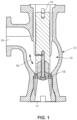
- Fig. 1 shows a valve plug assembly 10 assembled in accordance with the teachings of an exemplary embodiment of the present invention for use in the control valve 12 having a valve stem 14, a flow passage 16, and a valve seat 18.
- the control valve 12 includes an inlet 15 and an outlet 17 connected by the flow passage 16.
- the valve plug assembly 10 is coupled to the valve stem 14 and moved by any suitable actuator (not shown) between an open position in which the valve plug assembly 10 is spaced away from the valve seat 18, thereby permitting flow through the control valve 12, and a closed position in which the valve plug assembly 10 is seated against the valve seat 18, thereby prohibiting flow through the control valve 12.
- the plug assembly 10 includes a plug base 20 defining a longitudinal axis X and having a first end 22 and a second end 24.
- the first end 22 of the plug base 20 is arranged for attachment to the valve stem 14 of the control valve 12.
- the second end 24 of the plug base 20 includes a bore 26 extending along the longitudinal axis L, with the bore 26 including a first portion 28 extending into the plug base 20 a first distance L1 and a second portion 30 extending into the plug base 20 a second distance L2, with the second distance L2 being less than the first distance L1.
- the first portion 28 of the bore 26 has a first diameter D1 and the second portion 30 of the bore 26 has a second diameter D2, with the second diameter D2 being greater than the first diameter D1.
- the second portion 30 of the bore 26 extends from the second end 24 of the plug base 20 to an end or terminus 32.
- the terminus 32 is a conical terminus and forms a first seat 34.
- a spacer 36 has a through bore 38 and also includes a first end 40 and a second end 42.
- the spacer 36 is sized for insertion into the second portion 30 of the bore 26 of the plug base 20, and in the disclosed example the first end 40 of the spacer 36 includes a conical portion 44.
- the conical portion 44 is arranged to engage the first seat 34 at the terminus 32 of the second portion 30 of the bore 26 of the plug base.
- the second end 42 of the spacer 36 has a conical terminus 46 forming a second seat 48.
- a plug tip 50 includes a through bore 52, and a first end 54 having a conical portion 56 is arranged to engage the second seat 48 of the spacer 36.
- the plug tip 50 also includes a second end 58 shaped to engage the valve seat 18 of the control valve 12.
- a cap screw 60 includes ends 62 and 64 and is sized for insertion through the bore 52 of the plug tip 50, as well as through the through bore 38 of the spacer 36.
- the end 64 of the cap screw 60 is shaped to engage the plug tip 50, while the end 62 includes threads 66 to allow threaded engagement with cooperating threads 68 in the first portion 28 if the bore 26 of the plug base 20. Accordingly, the cap screw 60 mechanically secures the plug tip 50 to the plug base 20.
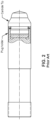
- the plug base 20 may include a side bore 70 as shown in Fig. 3 .
- the side bore 70 sized to receive an insert pin 72, which is sized for insertion into the side bore 70 to a position in which the insert pin 72 engages an inner portion 74 of the cap screw 60.
- the inner portion 74 of the cap screw 60 is disposed within the first portion 28 of the bore 26.
- the insert pin 72 may include a threaded portion 76 arranged to engage cooperating threads 78 on the side bore, thereby allowing an end 80 of the insert pin 72 to engage the inner portion 74 of the cap screw 60 via an interference fit.
- the inner portion 74 of the cap screw 60 may have a side bore 82, such that the end 80 of the insert pin 72 engages the side bore 82 of the cap screw.
- the end 80 of the insert pin 72 and the side bore 82 of the cap screw 60 may have cooperating threads.
- the insert pin 72 secures the cap screw 60 against rotation, thereby serving to secure the plug tip 50 against the second seat 48 of the spacer 36, and in turn securing the first end 40 of the spacer 36 against the first seat 34.
- an outer extent of the insert pin 72 pin used for anti-rotation purposes may be countersunk into the plug body 20, and may be covered by a liner, and thus the insert pin 72 is protected from the surrounding components.
- the plug tip 50 may be selected from a ceramic material, and may be carbide or tungsten carbide, or may be any other suitable material.
- the plug tip 50 may be provided with a counterbore 84, which is sized to receive a screw head 86 of the cap screw 60, such that all or a portion of the screw head 86 is recessed in the plug tip 50, and therefore wholly or at least partially out of the path of fluid flow.
- the first seat 34 and the first end 40 of the spacer 36 may be suitably shaped to cooperate with one another in order to cooperate to center the spacer relative to the longitudinal axis L.
- the second seat 48 on the second end 42 of the spacer 36 may also be suitably shaped to cooperate with one another to center the plug tip relative to the longitudinal axis L.
- these shapes are primarily cone or truncated cone shapes. However, other shapes may prove suitable.
- these cooperating shapes may be semi-spherical or other curved forms. In sum, the conical or other shapes facilitate or otherwise promote the self-centering of the spacer and the plug tip relative to the longitudinal axis L.
- the cap screw 60 may be constructed from Inconel 718, which in testing has shown to exhibit favorable strength properties. Those of skill in the relevant art, upon reading the present disclosure and obtaining the benefits thereof, may arrive at other shapes for the spacer 36 and the plug tip 50 to promote self-centering and/or longevity.
- the spacer 36 may be constructed from austenitic stainless steel, which offers a larger thermal expansion factor, although other materials may prove suitable. Such material may serve to compensate for the thermal expansion difference between the carbide tip and cap screw in the mechanically secured components, and maintain proper clamping stress for the connection. When constructed of austenitic stainless steel or other suitably and relatively soft materials, the spacer 36 may serve to function as a cushion for the relatively hard ceramic or carbide plug tip 50, and can serve to absorb impact forces thus inhibiting crack formation in high vibration applications.
- the plug tip 50 is hollow, and has a relatively even thickness, thus serving to avoid the creation of internal defects and stress during manufacturing, offering advantages over a solid plug tip.
- valve plug assembly When constructed, a valve plug assembly assembled in accordance with the exemplary teachings outlined herein may offer one or more technical advantages not achievable with prior art teachings.
- valve plug assembly employs mechanical fastening structures and methods, which promotes ease of manufacturing and improve the quality of the resulting assembly.
- the disclosed structures and methods promote a low- or lower-cost design, thus potentially offering commercial advantages.
- the use of select materials outlined herein free manufacturers from stringent requirements of shrink fit or brazing construction by allowing the use of lower cost, readily available, and standard materials.
- Another potential technical advantage is the disclosed aspects facilitate easier maintenance by allowing the end user to retrofit a worn plug tip, instead of replacing the entire valve plug assembly.
- one or more aspects of the present invention inhibit the development of harmful and hard-to-control internal stresses resulting from prior construction, such as may be found in the shrink fit process.
- one or more aspects of the present invention result in an assembly that offers better performance and longevity over a wider temperature range, which offers advantages over the prior art brazing assembly structure and method. This may be especially true for larger valve trim sizes.
- one or more aspects of the present disclosure promote control of stresses on the plug tip and other components, again favoring better performance over a wider temperature range.
Landscapes
- Engineering & Computer Science (AREA)
- General Engineering & Computer Science (AREA)
- Mechanical Engineering (AREA)
- Lift Valve (AREA)
- Valve Housings (AREA)
Claims (8)
- Ventilstopfenanordnung (10) zur Verwendung in einem Regelventil, das einen Ventilschaft, einen Durchflusskanal und einen in dem Durchflusskanal angeordneten Ventilsitz aufweist, wobei die Ventilstopfenanordnung (10) Folgendes umfasst:einen Stopfengrundkörper (20), der eine Längsachse definiert und ein erstes Ende (22) und ein zweites Ende (24) aufweist;wobei das erste Ende (22) des Stopfengrundkörpers (20) zur Anbringung an einem Ventilschaft des Regelventils eingerichtet ist;wobei das zweite Ende (24) des Stopfengrundkörpers (20) eine Bohrung (26) aufweist, die sich entlang der Längsachse erstreckt, wobei die Bohrung (26) einen ersten Abschnitt (28), der sich über eine erste Strecke (L1) in den Stopfengrundkörper (20) hinein erstreckt, undeinen zweiten Abschnitt (30), der sich über eine zweite Strecke (L2), die kleiner als die erste Strecke (L1) ist, in den Stopfengrundkörper (20) hinein erstreckt, aufweist, wobei ein inneres Ende des zweiten Abschnitts (30) der Bohrung (26) einen konischen Endbereich (32) aufweist, der einen ersten Sitz (34) ausbildet;wobei der erste Abschnitt (28) der Bohrung (26) einen ersten Durchmesser (D1) aufweist und der zweite Abschnitt (30) der Bohrung (26) einen zweiten Durchmesser (D2), der größer als der erste Durchmesser (D1) ist, aufweist;wobei der zweite Abschnitt (30) der Bohrung (26) sich von dem zweiten Ende (24) des Stopfengrundkörpers (20) zu dem konischen Endbereich (32) erstreckt;einen Abstandhalter (36), der eine Durchgangsbohrung (38), ein erstes Ende (40) und ein zweites Ende (42) aufweist, wobei der Abstandhalter (36) zum Einsetzen in den zweiten Abschnitt (30) der Bohrung (26) des Stopfengrundkörpers (20) bemessen ist, wobei das erste Ende (40) des Abstandhalters (36) eine konische Form aufweist, die dazu eingerichtet ist, mit dem ersten Sitz (34) in Eingriff zu gelangen, wobei das zweite Ende (42) des Abstandhalters (36) einen konischen Endbereich (46) aufweist, der einen zweiten Sitz (48) ausbildet;eine Stopfenspitze (50), die eine Durchgangsbohrung (52), ein erstes Ende (54) mit einer konischen Form, die dazu eingerichtet ist, mit dem zweiten Sitz (48) des Abstandhalters (36) in Eingriff zu gelangen, und ein zweites Ende (58), das dazu geformt ist, mit dem Ventilsitz (18) des Ventils (12) in Eingriff zu gelangen, aufweist; undeine Kopfschraube (60), die zum Einsetzen durch die Stopfenspitze (50) und die Durchgangsbohrung (38) des Abstandhalters (36) hindurch bemessen ist und zum Schraubeingriff mit dem ersten Abschnitt (28) der Bohrung (26) des Stopfengrundkörpers (20) eingerichtet ist;wobei die Kopfschraube (60) die Stopfenspitze (50) mechanisch an dem Stopfengrundkörper (20) befestigt,dadurch gekennzeichnet, dassder konische Endbereich (32) des zweiten Abschnitts (30) der Bohrung (26) mit dem ersten Abschnitt (28) der Bohrung (26) in Kontakt steht.
- Ventilstopfenanordnung (10) nach Anspruch 1, wobei die Stopfenspitze (50) aus einem Keramikmaterial ausgewählt ist oder wobei die Stopfenspitze (50) Carbid oder Wolframcarbid umfasst.
- Ventilstopfenanordnung (10) nach einem vorangehenden Anspruch, wobei die Stopfenspitze (50) eine Senkbohrung (84) aufweist und die Kopfschraube (60) einen Schraubenkopf (86) aufweist, der dazu bemessen ist, innerhalb der Senkbohrung (84) zu sitzen.
- Ventilstopfenanordnung (10) nach Anspruch 1, wobei das erste Ende (22) des Stopfengrundkörpers (20) zur direkten Anbringung an dem Ventilschaft des Regelventils eingerichtet ist.
- Ventilstopfenanordnung (10) nach Anspruch 4, wobei der Stopfengrundkörper (20) eine seitliche Bohrung (70) aufweist, die dazu bemessen ist, einen Einsetzstift (72) aufzunehmen, wobei der Einsetzstift (72) in der seitlichen Bohrung (70) dazu eingerichtet ist, in die Kopfschraube (60) einzugreifen und dadurch die Kopfschraube (60) gegen Verdrehung zu arretieren.
- Ventilstopfenanordnung (10) nach einem vorangehenden Anspruch, wobei das geformte erste Ende (40) des Abstandhalters (36) und der erste Sitz (34) zusammenwirken, um den Abstandhalter (36) bezogen auf die Längsachse zu zentrieren, und wobei das geformte erste Ende (54) der Stopfenspitze (50) und der zweite geformte Sitz (48) zusammenwirken, um die Stopfenspitze (50) bezogen auf die Längsachse zu zentrieren.
- Ventilstopfenanordnung (10) nach einem vorangehenden Anspruch und wobei der Abstandhalter (36) einen ersten Wärmeausdehnungskoeffizienten aufweist, die Stopfenspitze (50) einen zweiten Wärmeausdehnungskoeffizienten aufweist und die Kopfschraube (60) einen dritten Wärmeausdehnungskoeffizienten aufweist und wobei der erste Wärmeausdehnungskoeffizient größer als der zweite und dritte Wärmeausdehnungskoeffizient ist und wobei der zweite und dritte Wärmeausdehnungskoeffizient unterschiedlich sind.
- Ventilstopfenanordnung (10) nach einem vorangehenden Anspruch, wobei der Abstandhalter (36) aus austenitischem nichtrostendem Stahl gefertigt ist und weicher als die Stopfenspitze (50) ist, sodass der Abstandhalter (36) dazu eingerichtet ist, Stoßkräfte und/oder Wärmeausdehnungskräfte von der Stopfenspitze (50) zu absorbieren.
Applications Claiming Priority (2)
| Application Number | Priority Date | Filing Date | Title |
|---|---|---|---|
| US201762552904P | 2017-08-31 | 2017-08-31 | |
| PCT/IB2018/001418 WO2019043461A2 (en) | 2017-08-31 | 2018-08-31 | MECHANICAL FASTENING METHOD FOR CARBIDE TIP VALVE CAP |
Publications (3)
| Publication Number | Publication Date |
|---|---|
| EP3676519A2 EP3676519A2 (de) | 2020-07-08 |
| EP3676519A4 EP3676519A4 (de) | 2021-04-28 |
| EP3676519B1 true EP3676519B1 (de) | 2024-07-17 |
Family
ID=63684494
Family Applications (1)
| Application Number | Title | Priority Date | Filing Date |
|---|---|---|---|
| EP18849589.9A Active EP3676519B1 (de) | 2017-08-31 | 2018-08-31 | Mechanisches befestigungsverfahren für einen ventilstopfen mit hartmetallspitze |
Country Status (4)
| Country | Link |
|---|---|
| US (1) | US10948088B2 (de) |
| EP (1) | EP3676519B1 (de) |
| CN (2) | CN109424749A (de) |
| WO (1) | WO2019043461A2 (de) |
Families Citing this family (6)
| Publication number | Priority date | Publication date | Assignee | Title |
|---|---|---|---|---|
| CN109424749A (zh) * | 2017-08-31 | 2019-03-05 | 艾默生过程管理(天津)阀门有限公司 | 用于具有碳化物尖端的阀塞的机械紧固方法 |
| CN110625325B (zh) * | 2019-11-18 | 2021-02-19 | 上海中船三井造船柴油机有限公司 | 双燃料船用柴油机气缸盖的起动阀进气孔的加工方法 |
| FR3105041B1 (fr) | 2019-12-18 | 2023-04-21 | Commissariat Energie Atomique | Procédé de fabrication par compression isostatique à chaud d’une pièce outil |
| FR3105040B1 (fr) | 2019-12-18 | 2023-11-24 | Commissariat Energie Atomique | Procédé de fabrication par compression isostatique à chaud d’une pièce outil |
| US11280422B1 (en) * | 2020-12-14 | 2022-03-22 | Flowserve Management Company | Erosion resistant plug and seat valve |
| US11649897B1 (en) * | 2022-01-19 | 2023-05-16 | Fisher Controls International Llc | Valve plug apparatus for use with control valves |
Family Cites Families (23)
| Publication number | Priority date | Publication date | Assignee | Title |
|---|---|---|---|---|
| US251A (en) | 1837-07-05 | Improvement in rotary presses for pressing woolen and cotton goods | ||
| US2277A (en) | 1841-09-30 | Island | ||
| US2277251A (en) * | 1941-01-16 | 1942-03-24 | Edson F Palmer | Packing washer |
| US2981282A (en) * | 1958-09-12 | 1961-04-25 | Mack Company | Valve device |
| GB925610A (en) * | 1959-07-23 | 1963-05-08 | Erkki Niskanen | Improvements in conical plug valves |
| DE4300629C1 (de) | 1993-01-13 | 1994-03-24 | Draegerwerk Ag | Ventil mit Druckkompensation |
| US5878993A (en) | 1997-03-27 | 1999-03-09 | St. Germain; Stephen V. | Shielded globe valve seal mechanism |
| CN2455967Y (zh) * | 2000-12-25 | 2001-10-24 | 柴慈俭 | 农田管道用水闸阀 |
| US6991218B2 (en) * | 2002-09-13 | 2006-01-31 | Fisher Controls International Llc. | Control valve with retained pin for easy valve trim maintenance |
| CN201028227Y (zh) * | 2007-01-09 | 2008-02-27 | 王晓光 | 双层丝堵及双层排气丝堵 |
| JP2008169910A (ja) * | 2007-01-11 | 2008-07-24 | Fuji Koki Corp | 電動弁 |
| CN201715001U (zh) * | 2010-05-20 | 2011-01-19 | 青岛国胜工业有限公司 | 气瓶减压器用带平衡垫圈阀门体 |
| CO6340185A1 (es) * | 2010-05-24 | 2011-11-21 | Gutierrez Ismael Hernan Riano | Regulador economizador automático de flujo, de un fluído líquido |
| EP2646717B1 (de) * | 2010-12-01 | 2016-09-14 | Emerson Process Management (Tianjin) Valve Co., Ltd. | Verfahren zum verbinden einer keramischen steckerspitze und eines stahlträgerelements mit einer gewindeverbindung und klebstoff |
| US9316321B2 (en) * | 2011-05-09 | 2016-04-19 | Fisher Controls International, Llc | Multi-piece flow control apparatus for use with fluid valves |
| CN202108999U (zh) * | 2011-05-09 | 2012-01-11 | 叶仁富 | 变压器防盗放油阀及专用工具 |
| CN202152856U (zh) * | 2011-08-01 | 2012-02-29 | 艾默生过程管理(天津)阀门有限公司 | 用于阀的阀塞组件以及包括阀塞组件的阀 |
| US10094010B2 (en) * | 2014-06-19 | 2018-10-09 | The Ohio State University | Cobalt-free, galling and wear resistant austenitic stainless steel hard-facing alloy |
| US9995400B2 (en) * | 2015-02-04 | 2018-06-12 | Fisher Controls International Llc | Thermally compensated valve trim component |
| US10197183B2 (en) | 2015-02-12 | 2019-02-05 | Fisher Controls International Llc | Valve stem and plug connections and staking tools |
| CN204664462U (zh) * | 2015-05-19 | 2015-09-23 | 王怀玉 | 新型锥塞流量调节控制阀 |
| KR20170065930A (ko) * | 2015-12-04 | 2017-06-14 | (주)대일기계 | 밸브 |
| CN109424749A (zh) * | 2017-08-31 | 2019-03-05 | 艾默生过程管理(天津)阀门有限公司 | 用于具有碳化物尖端的阀塞的机械紧固方法 |
-
2018
- 2018-08-31 CN CN201811014587.6A patent/CN109424749A/zh active Pending
- 2018-08-31 CN CN201821425499.0U patent/CN209671641U/zh active Active
- 2018-08-31 EP EP18849589.9A patent/EP3676519B1/de active Active
- 2018-08-31 WO PCT/IB2018/001418 patent/WO2019043461A2/en not_active Ceased
- 2018-08-31 US US16/119,177 patent/US10948088B2/en active Active
Also Published As
| Publication number | Publication date |
|---|---|
| US10948088B2 (en) | 2021-03-16 |
| US20190063616A1 (en) | 2019-02-28 |
| WO2019043461A3 (en) | 2019-05-02 |
| EP3676519A2 (de) | 2020-07-08 |
| CN109424749A (zh) | 2019-03-05 |
| CN209671641U (zh) | 2019-11-22 |
| WO2019043461A2 (en) | 2019-03-07 |
| EP3676519A4 (de) | 2021-04-28 |
Similar Documents
| Publication | Publication Date | Title |
|---|---|---|
| EP3676519B1 (de) | Mechanisches befestigungsverfahren für einen ventilstopfen mit hartmetallspitze | |
| EP0224345B1 (de) | Ventilsitzring und entsprechender Zylinderkopf | |
| EP2033285B1 (de) | Zündkerze mit feindrahtmasseelektrode | |
| US20200173317A1 (en) | Cylinder head assembly having a hybrid valve seat insert | |
| US20080260889A1 (en) | Nozzle Tip for High Melt Pressure Applications | |
| CN105840847B (zh) | 热补偿阀内件部件 | |
| US10989315B2 (en) | Method of attaching or replacing a plug assembly | |
| US20200182079A1 (en) | Bypass valve assembly for turbine generators | |
| US20180306440A1 (en) | Combustor basket cooling ring | |
| US7941922B2 (en) | Method of manufacturing a lightweight valve | |
| CN105009389B (zh) | 火花塞 | |
| US6938602B2 (en) | Multi-piece valve for reciprocating piston engines | |
| EP3688346B1 (de) | Karbideinsatzanordnung mit verschmolzener halterung | |
| US20010015601A1 (en) | Fixing sleeve for a spark plug | |
| US20080011975A1 (en) | Wear-resistant plug head | |
| US20180274401A1 (en) | Valve for internal combustion engines having a guide vane for coolant | |
| US20180074529A1 (en) | Pressure-reducing valve | |
| CN111247317B (zh) | 提升阀及其制造方法 | |
| CN208634408U (zh) | 用于控制阀的阀塞组件 | |
| WO2009137729A2 (en) | Choke trim assembly | |
| CN216407755U (zh) | 用在燃油喷射器中的控制阀及燃油喷射器 | |
| JP2008277251A (ja) | 内燃機関用スパークプラグ | |
| CN110296224B (zh) | 以钎焊工艺组装的阀塞 | |
| CN110030135B (zh) | 用于配量流体的阀,尤其燃料喷射阀 | |
| JP2006104763A (ja) | スクリューポイント |
Legal Events
| Date | Code | Title | Description |
|---|---|---|---|
| STAA | Information on the status of an ep patent application or granted ep patent |
Free format text: STATUS: THE INTERNATIONAL PUBLICATION HAS BEEN MADE |
|
| PUAI | Public reference made under article 153(3) epc to a published international application that has entered the european phase |
Free format text: ORIGINAL CODE: 0009012 |
|
| STAA | Information on the status of an ep patent application or granted ep patent |
Free format text: STATUS: REQUEST FOR EXAMINATION WAS MADE |
|
| 17P | Request for examination filed |
Effective date: 20200313 |
|
| AK | Designated contracting states |
Kind code of ref document: A2 Designated state(s): AL AT BE BG CH CY CZ DE DK EE ES FI FR GB GR HR HU IE IS IT LI LT LU LV MC MK MT NL NO PL PT RO RS SE SI SK SM TR |
|
| AX | Request for extension of the european patent |
Extension state: BA ME |
|
| DAV | Request for validation of the european patent (deleted) | ||
| DAX | Request for extension of the european patent (deleted) | ||
| REG | Reference to a national code |
Ref country code: DE Ref legal event code: R079 Free format text: PREVIOUS MAIN CLASS: F16K0001000000 Ipc: F16K0001360000 Ref document number: 602018071976 Country of ref document: DE |
|
| A4 | Supplementary search report drawn up and despatched |
Effective date: 20210325 |
|
| RIC1 | Information provided on ipc code assigned before grant |
Ipc: F16K 1/36 20060101AFI20210319BHEP Ipc: F16K 1/48 20060101ALI20210319BHEP |
|
| STAA | Information on the status of an ep patent application or granted ep patent |
Free format text: STATUS: EXAMINATION IS IN PROGRESS |
|
| 17Q | First examination report despatched |
Effective date: 20220707 |
|
| GRAP | Despatch of communication of intention to grant a patent |
Free format text: ORIGINAL CODE: EPIDOSNIGR1 |
|
| STAA | Information on the status of an ep patent application or granted ep patent |
Free format text: STATUS: GRANT OF PATENT IS INTENDED |
|
| INTG | Intention to grant announced |
Effective date: 20240212 |
|
| GRAS | Grant fee paid |
Free format text: ORIGINAL CODE: EPIDOSNIGR3 |
|
| GRAA | (expected) grant |
Free format text: ORIGINAL CODE: 0009210 |
|
| STAA | Information on the status of an ep patent application or granted ep patent |
Free format text: STATUS: THE PATENT HAS BEEN GRANTED |
|
| AK | Designated contracting states |
Kind code of ref document: B1 Designated state(s): AL AT BE BG CH CY CZ DE DK EE ES FI FR GB GR HR HU IE IS IT LI LT LU LV MC MK MT NL NO PL PT RO RS SE SI SK SM TR |
|
| P01 | Opt-out of the competence of the unified patent court (upc) registered |
Free format text: CASE NUMBER: APP_34983/2024 Effective date: 20240611 |
|
| REG | Reference to a national code |
Ref country code: CH Ref legal event code: EP |
|
| REG | Reference to a national code |
Ref country code: DE Ref legal event code: R096 Ref document number: 602018071976 Country of ref document: DE |
|
| REG | Reference to a national code |
Ref country code: IE Ref legal event code: FG4D |
|
| REG | Reference to a national code |
Ref country code: LT Ref legal event code: MG9D |
|
| REG | Reference to a national code |
Ref country code: NL Ref legal event code: MP Effective date: 20240717 |
|
| PG25 | Lapsed in a contracting state [announced via postgrant information from national office to epo] |
Ref country code: PT Free format text: LAPSE BECAUSE OF FAILURE TO SUBMIT A TRANSLATION OF THE DESCRIPTION OR TO PAY THE FEE WITHIN THE PRESCRIBED TIME-LIMIT Effective date: 20241118 |
|
| REG | Reference to a national code |
Ref country code: AT Ref legal event code: MK05 Ref document number: 1704427 Country of ref document: AT Kind code of ref document: T Effective date: 20240717 |
|
| PG25 | Lapsed in a contracting state [announced via postgrant information from national office to epo] |
Ref country code: NL Free format text: LAPSE BECAUSE OF FAILURE TO SUBMIT A TRANSLATION OF THE DESCRIPTION OR TO PAY THE FEE WITHIN THE PRESCRIBED TIME-LIMIT Effective date: 20240717 |
|
| PG25 | Lapsed in a contracting state [announced via postgrant information from national office to epo] |
Ref country code: PT Free format text: LAPSE BECAUSE OF FAILURE TO SUBMIT A TRANSLATION OF THE DESCRIPTION OR TO PAY THE FEE WITHIN THE PRESCRIBED TIME-LIMIT Effective date: 20241118 Ref country code: NL Free format text: LAPSE BECAUSE OF FAILURE TO SUBMIT A TRANSLATION OF THE DESCRIPTION OR TO PAY THE FEE WITHIN THE PRESCRIBED TIME-LIMIT Effective date: 20240717 |
|
| PG25 | Lapsed in a contracting state [announced via postgrant information from national office to epo] |
Ref country code: NO Free format text: LAPSE BECAUSE OF FAILURE TO SUBMIT A TRANSLATION OF THE DESCRIPTION OR TO PAY THE FEE WITHIN THE PRESCRIBED TIME-LIMIT Effective date: 20241017 |
|
| PG25 | Lapsed in a contracting state [announced via postgrant information from national office to epo] |
Ref country code: GR Free format text: LAPSE BECAUSE OF FAILURE TO SUBMIT A TRANSLATION OF THE DESCRIPTION OR TO PAY THE FEE WITHIN THE PRESCRIBED TIME-LIMIT Effective date: 20241018 Ref country code: FI Free format text: LAPSE BECAUSE OF FAILURE TO SUBMIT A TRANSLATION OF THE DESCRIPTION OR TO PAY THE FEE WITHIN THE PRESCRIBED TIME-LIMIT Effective date: 20240717 Ref country code: PL Free format text: LAPSE BECAUSE OF FAILURE TO SUBMIT A TRANSLATION OF THE DESCRIPTION OR TO PAY THE FEE WITHIN THE PRESCRIBED TIME-LIMIT Effective date: 20240717 |
|
| PG25 | Lapsed in a contracting state [announced via postgrant information from national office to epo] |
Ref country code: BG Free format text: LAPSE BECAUSE OF FAILURE TO SUBMIT A TRANSLATION OF THE DESCRIPTION OR TO PAY THE FEE WITHIN THE PRESCRIBED TIME-LIMIT Effective date: 20240717 |
|
| PG25 | Lapsed in a contracting state [announced via postgrant information from national office to epo] |
Ref country code: LV Free format text: LAPSE BECAUSE OF FAILURE TO SUBMIT A TRANSLATION OF THE DESCRIPTION OR TO PAY THE FEE WITHIN THE PRESCRIBED TIME-LIMIT Effective date: 20240717 |
|
| PG25 | Lapsed in a contracting state [announced via postgrant information from national office to epo] |
Ref country code: IS Free format text: LAPSE BECAUSE OF FAILURE TO SUBMIT A TRANSLATION OF THE DESCRIPTION OR TO PAY THE FEE WITHIN THE PRESCRIBED TIME-LIMIT Effective date: 20241117 Ref country code: AT Free format text: LAPSE BECAUSE OF FAILURE TO SUBMIT A TRANSLATION OF THE DESCRIPTION OR TO PAY THE FEE WITHIN THE PRESCRIBED TIME-LIMIT Effective date: 20240717 |
|
| PG25 | Lapsed in a contracting state [announced via postgrant information from national office to epo] |
Ref country code: HR Free format text: LAPSE BECAUSE OF FAILURE TO SUBMIT A TRANSLATION OF THE DESCRIPTION OR TO PAY THE FEE WITHIN THE PRESCRIBED TIME-LIMIT Effective date: 20240717 |
|
| PG25 | Lapsed in a contracting state [announced via postgrant information from national office to epo] |
Ref country code: ES Free format text: LAPSE BECAUSE OF FAILURE TO SUBMIT A TRANSLATION OF THE DESCRIPTION OR TO PAY THE FEE WITHIN THE PRESCRIBED TIME-LIMIT Effective date: 20240717 Ref country code: RS Free format text: LAPSE BECAUSE OF FAILURE TO SUBMIT A TRANSLATION OF THE DESCRIPTION OR TO PAY THE FEE WITHIN THE PRESCRIBED TIME-LIMIT Effective date: 20241017 |
|
| PG25 | Lapsed in a contracting state [announced via postgrant information from national office to epo] |
Ref country code: RS Free format text: LAPSE BECAUSE OF FAILURE TO SUBMIT A TRANSLATION OF THE DESCRIPTION OR TO PAY THE FEE WITHIN THE PRESCRIBED TIME-LIMIT Effective date: 20241017 Ref country code: PL Free format text: LAPSE BECAUSE OF FAILURE TO SUBMIT A TRANSLATION OF THE DESCRIPTION OR TO PAY THE FEE WITHIN THE PRESCRIBED TIME-LIMIT Effective date: 20240717 Ref country code: NO Free format text: LAPSE BECAUSE OF FAILURE TO SUBMIT A TRANSLATION OF THE DESCRIPTION OR TO PAY THE FEE WITHIN THE PRESCRIBED TIME-LIMIT Effective date: 20241017 Ref country code: LV Free format text: LAPSE BECAUSE OF FAILURE TO SUBMIT A TRANSLATION OF THE DESCRIPTION OR TO PAY THE FEE WITHIN THE PRESCRIBED TIME-LIMIT Effective date: 20240717 Ref country code: IS Free format text: LAPSE BECAUSE OF FAILURE TO SUBMIT A TRANSLATION OF THE DESCRIPTION OR TO PAY THE FEE WITHIN THE PRESCRIBED TIME-LIMIT Effective date: 20241117 Ref country code: HR Free format text: LAPSE BECAUSE OF FAILURE TO SUBMIT A TRANSLATION OF THE DESCRIPTION OR TO PAY THE FEE WITHIN THE PRESCRIBED TIME-LIMIT Effective date: 20240717 Ref country code: GR Free format text: LAPSE BECAUSE OF FAILURE TO SUBMIT A TRANSLATION OF THE DESCRIPTION OR TO PAY THE FEE WITHIN THE PRESCRIBED TIME-LIMIT Effective date: 20241018 Ref country code: FI Free format text: LAPSE BECAUSE OF FAILURE TO SUBMIT A TRANSLATION OF THE DESCRIPTION OR TO PAY THE FEE WITHIN THE PRESCRIBED TIME-LIMIT Effective date: 20240717 Ref country code: ES Free format text: LAPSE BECAUSE OF FAILURE TO SUBMIT A TRANSLATION OF THE DESCRIPTION OR TO PAY THE FEE WITHIN THE PRESCRIBED TIME-LIMIT Effective date: 20240717 Ref country code: BG Free format text: LAPSE BECAUSE OF FAILURE TO SUBMIT A TRANSLATION OF THE DESCRIPTION OR TO PAY THE FEE WITHIN THE PRESCRIBED TIME-LIMIT Effective date: 20240717 Ref country code: AT Free format text: LAPSE BECAUSE OF FAILURE TO SUBMIT A TRANSLATION OF THE DESCRIPTION OR TO PAY THE FEE WITHIN THE PRESCRIBED TIME-LIMIT Effective date: 20240717 |
|
| REG | Reference to a national code |
Ref country code: CH Ref legal event code: PL |
|
| PG25 | Lapsed in a contracting state [announced via postgrant information from national office to epo] |
Ref country code: SM Free format text: LAPSE BECAUSE OF FAILURE TO SUBMIT A TRANSLATION OF THE DESCRIPTION OR TO PAY THE FEE WITHIN THE PRESCRIBED TIME-LIMIT Effective date: 20240717 Ref country code: DK Free format text: LAPSE BECAUSE OF FAILURE TO SUBMIT A TRANSLATION OF THE DESCRIPTION OR TO PAY THE FEE WITHIN THE PRESCRIBED TIME-LIMIT Effective date: 20240717 Ref country code: RO Free format text: LAPSE BECAUSE OF FAILURE TO SUBMIT A TRANSLATION OF THE DESCRIPTION OR TO PAY THE FEE WITHIN THE PRESCRIBED TIME-LIMIT Effective date: 20240717 |
|
| PG25 | Lapsed in a contracting state [announced via postgrant information from national office to epo] |
Ref country code: LU Free format text: LAPSE BECAUSE OF NON-PAYMENT OF DUE FEES Effective date: 20240831 |
|
| REG | Reference to a national code |
Ref country code: DE Ref legal event code: R097 Ref document number: 602018071976 Country of ref document: DE |
|
| PG25 | Lapsed in a contracting state [announced via postgrant information from national office to epo] |
Ref country code: CH Free format text: LAPSE BECAUSE OF NON-PAYMENT OF DUE FEES Effective date: 20240831 Ref country code: MC Free format text: LAPSE BECAUSE OF FAILURE TO SUBMIT A TRANSLATION OF THE DESCRIPTION OR TO PAY THE FEE WITHIN THE PRESCRIBED TIME-LIMIT Effective date: 20240717 Ref country code: EE Free format text: LAPSE BECAUSE OF FAILURE TO SUBMIT A TRANSLATION OF THE DESCRIPTION OR TO PAY THE FEE WITHIN THE PRESCRIBED TIME-LIMIT Effective date: 20240717 |
|
| PG25 | Lapsed in a contracting state [announced via postgrant information from national office to epo] |
Ref country code: CZ Free format text: LAPSE BECAUSE OF FAILURE TO SUBMIT A TRANSLATION OF THE DESCRIPTION OR TO PAY THE FEE WITHIN THE PRESCRIBED TIME-LIMIT Effective date: 20240717 |
|
| PG25 | Lapsed in a contracting state [announced via postgrant information from national office to epo] |
Ref country code: SK Free format text: LAPSE BECAUSE OF FAILURE TO SUBMIT A TRANSLATION OF THE DESCRIPTION OR TO PAY THE FEE WITHIN THE PRESCRIBED TIME-LIMIT Effective date: 20240717 |
|
| PLBE | No opposition filed within time limit |
Free format text: ORIGINAL CODE: 0009261 |
|
| STAA | Information on the status of an ep patent application or granted ep patent |
Free format text: STATUS: NO OPPOSITION FILED WITHIN TIME LIMIT |
|
| 26N | No opposition filed |
Effective date: 20250422 |
|
| REG | Reference to a national code |
Ref country code: BE Ref legal event code: MM Effective date: 20240831 |
|
| PG25 | Lapsed in a contracting state [announced via postgrant information from national office to epo] |
Ref country code: BE Free format text: LAPSE BECAUSE OF NON-PAYMENT OF DUE FEES Effective date: 20240831 |
|
| PG25 | Lapsed in a contracting state [announced via postgrant information from national office to epo] |
Ref country code: IE Free format text: LAPSE BECAUSE OF NON-PAYMENT OF DUE FEES Effective date: 20240831 |
|
| PG25 | Lapsed in a contracting state [announced via postgrant information from national office to epo] |
Ref country code: SE Free format text: LAPSE BECAUSE OF FAILURE TO SUBMIT A TRANSLATION OF THE DESCRIPTION OR TO PAY THE FEE WITHIN THE PRESCRIBED TIME-LIMIT Effective date: 20240717 |
|
| PGFP | Annual fee paid to national office [announced via postgrant information from national office to epo] |
Ref country code: DE Payment date: 20250724 Year of fee payment: 8 |
|
| PGFP | Annual fee paid to national office [announced via postgrant information from national office to epo] |
Ref country code: GB Payment date: 20250724 Year of fee payment: 8 |
|
| PGFP | Annual fee paid to national office [announced via postgrant information from national office to epo] |
Ref country code: FR Payment date: 20250723 Year of fee payment: 8 |
|
| PG25 | Lapsed in a contracting state [announced via postgrant information from national office to epo] |
Ref country code: CY Free format text: LAPSE BECAUSE OF FAILURE TO SUBMIT A TRANSLATION OF THE DESCRIPTION OR TO PAY THE FEE WITHIN THE PRESCRIBED TIME-LIMIT; INVALID AB INITIO Effective date: 20180831 Ref country code: IT Free format text: LAPSE BECAUSE OF FAILURE TO SUBMIT A TRANSLATION OF THE DESCRIPTION OR TO PAY THE FEE WITHIN THE PRESCRIBED TIME-LIMIT Effective date: 20240717 |
|
| PG25 | Lapsed in a contracting state [announced via postgrant information from national office to epo] |
Ref country code: HU Free format text: LAPSE BECAUSE OF FAILURE TO SUBMIT A TRANSLATION OF THE DESCRIPTION OR TO PAY THE FEE WITHIN THE PRESCRIBED TIME-LIMIT; INVALID AB INITIO Effective date: 20180831 |