EP3676657B1 - Gasgekühlter faraday-rotator und verfahren - Google Patents
Gasgekühlter faraday-rotator und verfahren Download PDFInfo
- Publication number
- EP3676657B1 EP3676657B1 EP18850991.3A EP18850991A EP3676657B1 EP 3676657 B1 EP3676657 B1 EP 3676657B1 EP 18850991 A EP18850991 A EP 18850991A EP 3676657 B1 EP3676657 B1 EP 3676657B1
- Authority
- EP
- European Patent Office
- Prior art keywords
- faraday
- optic
- faraday optic
- heating
- outer edge
- Prior art date
- Legal status (The legal status is an assumption and is not a legal conclusion. Google has not performed a legal analysis and makes no representation as to the accuracy of the status listed.)
- Active
Links
Images

Classifications
-
- G—PHYSICS
- G02—OPTICS
- G02B—OPTICAL ELEMENTS, SYSTEMS OR APPARATUS
- G02B27/00—Optical systems or apparatus not provided for by any of the groups G02B1/00 - G02B26/00, G02B30/00
- G02B27/28—Optical systems or apparatus not provided for by any of the groups G02B1/00 - G02B26/00, G02B30/00 for polarising
-
- G—PHYSICS
- G02—OPTICS
- G02F—OPTICAL DEVICES OR ARRANGEMENTS FOR THE CONTROL OF LIGHT BY MODIFICATION OF THE OPTICAL PROPERTIES OF THE MEDIA OF THE ELEMENTS INVOLVED THEREIN; NON-LINEAR OPTICS; FREQUENCY-CHANGING OF LIGHT; OPTICAL LOGIC ELEMENTS; OPTICAL ANALOGUE/DIGITAL CONVERTERS
- G02F1/00—Devices or arrangements for the control of the intensity, colour, phase, polarisation or direction of light arriving from an independent light source, e.g. switching, gating or modulating; Non-linear optics
- G02F1/01—Devices or arrangements for the control of the intensity, colour, phase, polarisation or direction of light arriving from an independent light source, e.g. switching, gating or modulating; Non-linear optics for the control of the intensity, phase, polarisation or colour
- G02F1/0136—Devices or arrangements for the control of the intensity, colour, phase, polarisation or direction of light arriving from an independent light source, e.g. switching, gating or modulating; Non-linear optics for the control of the intensity, phase, polarisation or colour for the control of polarisation, e.g. state of polarisation [SOP] control, polarisation scrambling, TE-TM mode conversion or separation
-
- G—PHYSICS
- G02—OPTICS
- G02F—OPTICAL DEVICES OR ARRANGEMENTS FOR THE CONTROL OF LIGHT BY MODIFICATION OF THE OPTICAL PROPERTIES OF THE MEDIA OF THE ELEMENTS INVOLVED THEREIN; NON-LINEAR OPTICS; FREQUENCY-CHANGING OF LIGHT; OPTICAL LOGIC ELEMENTS; OPTICAL ANALOGUE/DIGITAL CONVERTERS
- G02F1/00—Devices or arrangements for the control of the intensity, colour, phase, polarisation or direction of light arriving from an independent light source, e.g. switching, gating or modulating; Non-linear optics
- G02F1/01—Devices or arrangements for the control of the intensity, colour, phase, polarisation or direction of light arriving from an independent light source, e.g. switching, gating or modulating; Non-linear optics for the control of the intensity, phase, polarisation or colour
- G02F1/09—Devices or arrangements for the control of the intensity, colour, phase, polarisation or direction of light arriving from an independent light source, e.g. switching, gating or modulating; Non-linear optics for the control of the intensity, phase, polarisation or colour based on magneto-optical elements, e.g. exhibiting Faraday effect
-
- G—PHYSICS
- G02—OPTICS
- G02F—OPTICAL DEVICES OR ARRANGEMENTS FOR THE CONTROL OF LIGHT BY MODIFICATION OF THE OPTICAL PROPERTIES OF THE MEDIA OF THE ELEMENTS INVOLVED THEREIN; NON-LINEAR OPTICS; FREQUENCY-CHANGING OF LIGHT; OPTICAL LOGIC ELEMENTS; OPTICAL ANALOGUE/DIGITAL CONVERTERS
- G02F2203/00—Function characteristic
- G02F2203/21—Thermal instability, i.e. DC drift, of an optical modulator; Arrangements or methods for the reduction thereof
Definitions
- the present technology relates to Faraday rotators, and more specifically, relates to techniques which may dramatically improve the average power handling capability of Faraday rotators.
- the present technology involves a gas cooled high average power faraday rotator.
- Faraday rotators are used in laser systems for polarization switching, isolation of laser amplifier components against back reflection, and depolarization correction.
- these devices typically use crystals or glasses that have high Verdet constant, which sets the rotation for a given pathlength and fixed magnetic field. It is desirable to minimize optical pathlength both for wavefront reasons as well as b-integral and thermal effects. It is also desirable to use fixed magnets to create compact devices. This has generally converged the industry around Terbium doped optical media which display a relatively high Verdet constant and can be doped into a variety of materials including Terbium Gallium Garnet (TGG), Terbium doped glasses, and Potassium Terbium Fluoride (KTF).
- TGG Terbium Gallium Garnet
- KTF Potassium Terbium Fluoride
- US2014/218795 discloses transparent heat-conductive layers of significant thickness bonded or adhered to opposing optical faces of a Faraday optic to form a Faraday optic structure that can be used with beam-folding mirrors and an external magnetic field to form a multi-pass Faraday rotator with minimal thermal gradient across the beam within the Faraday optic.
- the transparent heat conductive layers conduct heat through the Faraday optic substantially parallel to the beam propagation axis for each pass through the Faraday optic structure and thereby reduce thermal gradients across the beam cross section that would otherwise contribute to thermal lens focal shifts and thermal birefringence in the Faraday optic structure.
- the multi-pass Faraday rotator of this invention is suitable for use with any device based upon the Faraday effect such as optical isolators, optical circulators and Faraday mirrors that are scalable with beam size to power levels in excess of 2 kW.
- US2012/105931 discloses an electro-optic device that includes an electro-optic crystal having a predetermined thickness, a first face and a second face.
- the electro-optic device also includes a first electrode substrate disposed opposing the first face.
- the first electrode substrate includes a first substrate material having a first thickness and a first electrode coating coupled to the first substrate material.
- the electro-optic device further includes a second electrode substrate disposed opposing the second face.
- the second electrode substrate includes a second substrate material having a second thickness and a second electrode coating coupled to the second substrate material.
- the electro-optic device additionally includes a voltage source electrically coupled to the first electrode coating and the second electrode coating.
- a compact narrow band imaging system includes a vapor cell having a gas that receives and transmits light in accordance with the Faraday effect.
- a magnetic source is provided for applying a magnetic field to the vapor cell.
- Crossed polarizers are disposed before and after the vapor cell creating a Faraday optical filter. The only light that passes through the filter is light within a narrow band near the absorption peaks of the vapor.
- Other optical elements of the imaging system including filters, image detectors, electron multipliers, signal digitizers, and heat filters are co-located within the imaging system's common thermal isolation container to provide improved performance.
- the compact system is suitable for wide area surveillance, including daylight surveillance for combustion sources such as forest fires and missile exhaust.
- the present invetion is defined by the enclosed claims.
- the present technology enables scaling of average power handling from current sub-kW demonstrations to 100 kW - 1 MW capabilities. Applying the present technology to a Faraday rotator's optical components enables several orders of magnitude increase in average power and energy handling capability of these devices.
- Faraday rotators are used in laser systems for polarization switching, isolation of laser amplifier components against back reflection and depolarization correction. Currently these devices are limited in average power handling capability.
- High speed gas cooling efficiently removes thermal loading from Faraday optic faces while minimizing the thermal wavefront and thermal birefringence by creating a longitudinal thermal gradient.
- a recirculating gas cooling manifold accelerates the gas over the surface of the slab to create a turbulent flow condition which maximizes the surface cooling rate.
- the present technology further provides a spatially uniform thermal profile on the Faraday slabs.
- One embodiment includes a uniformly heated slab that is insulated around the perimeter.
- This device is useful in many applications, including in the high average power laser drivers for inertial fusion energy, drivers for laser accelerator systems, defense applications, laser peening, welding, cutting and additive manufacture.
- the present technology may enable several orders of magnitude increase in average power and energy handling capability of Faraday rotator optical components.
- the optical aperture of a Faraday rotator for a particular laser system is set nominally by the laser damage threshold of the Faraday material.
- the thickness of the material is set by the magnet design required for uniformity and desired rotation at this aperture. With these two values known along with the absorption coefficient of the particular Faraday material chosen (see Table 1 of typical materials), one can calculate the absorbed power at the use location in the laser system. Table 1.
- High speed helium gas cooling efficiently removes several W/cm 2 thermal loading from amplifier faces while minimizing the thermal wavefront and thermal birefringence by creating a longitudinal thermal gradient.
- a recirculating helium cooling manifold accelerates the gas over the surface of the slab to create a turbulent flow condition which maximizes the surface cooling rate.
- An example of such a system sufficient for a 100 kW class rotator would be a system pressurized with helium to ⁇ 45 psi and flowing at a rate of ⁇ Mach 0.1 (turbulent flow conditions) over the surface of the Faraday material slab surface.
- This technology allows the heat removal to be accomplished in transmission, so the problem can be attacked by changing aperture size and/or by splitting the material into thinner and thinner slabs to achieve desired results.
- the thermal loading is much lower than the amplifiers in the same system and comparable to current low power thermal loads on existing amplifiers.
- a 100 kW laser system that must double pass a Faraday rotator made of TGG with an aperture of 5 x 5 cm 2 and a thickness of 3 cm.
- the total thermal power absorbed in the crystal is 1800 W. If this crystal is split into 6 slabs where each slab is 5 mm thick, then the thermal loading that must be removed from each surface is 6 W/cm 2 on each surface, which is well within the capability of high speed gas cooling.
- helium is the preferred gas due to it low refractive index and low dn/dT, minimizing turbulence and scattering effects on the transmitted beam.
- the second step is creating the most spatially uniform thermal profile on the Faraday slabs.
- the techniques used in the present invention are not possible on an amplifier due to the much lower magnitude thermal load and the lack of requirement for edge cladding of a Faraday rotator material. Since it is not possible to completely fill the optical aperture with the beam (since this would incur huge diffractive loss and beam quality degradation on the transmitted beam), the present invention uses edge heaters to accomplish the thermal balance.
- heaters e.g., thin film sheet heaters
- These also could be shaped to create a spatially dependent heat load across the edge of the slab to improve uniformity. This enables each unit to be independent and separately tunable for flat thermal profile.
- the optical mode-fill, slab thickness and heater power are all variables that can be tuned to achieve uniformity. This concept is depicted in FIG.
- FIG. 1 which is a cross-sectional side view showing the Faraday material 10 in a series of slabs, Helium gas cooling 12, gas cooling vanes including portions 13 and 14, insulating material (e.g., insulating potting compound) 15, heaters 16, pressure vessel windows 18 and 20 and magnetic array housing 22 needed to achieve a high average power Faraday rotator.
- the figure shows laser beam 24 passing through the Faraday material 10.
- the outer periphery of the slabs can be round or square or any shape desired. It is desirable to make each slab to be uniformly heated such that there is no cool boundary around the beam. The heater for each slab may be in contact with the slab all the way around the slab.
- the side of the heater that is opposite to the slab is in contact with the insulating material and the insulating material is in contact with the magnetic housing.
- the gas flows between each slab.
- the magnetic array housing includes openings between the cooling vanes to allow gas to flow between each Faraday slab.
- the gas cooling vanes can be formed of magnetic material.
- a portion 13 of the cooling vane is formed of aluminum and a portion 14 is formed of magnetic material.
- the wavefront distortion is analogous to white noise and has been demonstrated as a cooling method to provide wavefront errors which are below measurement capability.
- a plurality of slabs is used because it is desirable to provide as close to a longitudinal thermal gradient as possible. Large temperature rises are undesirable (the thicker the material the temperature goes up as t 2 set by thermal conductivity of the material. However, for lower power systems one slab could work.
- One embodiment uses only two slabs of the material with a rotator between.
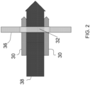
- a second method of heating is to project heater beams 30 onto the periphery of each slab (Faraday optic) 32.
- This can be accomplished locally with IR emitters or remotely by imaging optical beams generated by diodes or another laser source.
- the figure also shows a cooling vane 36 and laser beam 38.
- These techniques can be combined with the current technique of a birefringence compensated design. Such combination adds complication but would extend average power capability even further.
- the Faraday technology can be scaled from the current scale ⁇ ⁇ 1 kW to 100 kW and potentially extend to >1 MW class laser systems. This scaling will enable these lasers to function at this level and thereby enable accelerator, secondary radiation source, and defense applications.
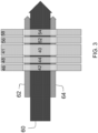
- FIG. 3 shows a birefringence compensated design having a Quartz rotator optic 40 between two sources of birefringence. Rotator optic 40 is cooled with cooling vane 41. The requirement is that the two sources be well matched/symmetric about the quartz rotator.
- One source comprises two Faraday optic slabs 42 and 44, including respective cooling vanes 46 and 48.
- the other source comprises two Faraday optic slabs 52 and 54, including respective cooling vanes 56 and 58,
- the figure also shows laser beam 60 and the heater beams 62 and 64.
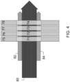
- FIG. 4 shows a design similar to FIG.
- the figure shows Faraday optic slabs 71-74, with respective cooling vanes 75-78. the figure also shows laser beam 80 and heater beams 82 and 84. Another option would be absorbing glass mounted as a frame around the optic. Light could then be directed at the glass for purposes of heating - so this method is optically addressed and could add spatial sculpting to achieve better uniformity performance.
Landscapes
- Physics & Mathematics (AREA)
- Nonlinear Science (AREA)
- General Physics & Mathematics (AREA)
- Optics & Photonics (AREA)
- Engineering & Computer Science (AREA)
- Power Engineering (AREA)
- Lasers (AREA)
- Optical Modulation, Optical Deflection, Nonlinear Optics, Optical Demodulation, Optical Logic Elements (AREA)
- Polarising Elements (AREA)
Claims (17)
- Vorrichtung, die folgendes umfasst:mindestens eine Faraday-Optik (10; 32; 42, 44, 52, 54; 71, 72, 73, 74) mit gegenüberliegenden optischen Seiten, durch die eine Strahlausbreitungsachse verläuft, die orthogonal zu den gegenüberliegenden optischen Seiten ist;Mittel (16; 30; 62, 64; 82, 84) zum Erhitzen eines Teils der mindestens einen Faraday-Optik (10; 32; 42, 44, 52, 54; 71, 72, 73, 74),ein Gaskühlungssystem (12, 13, 14; 36; 46, 48, 56, 58; 75, 76, 77, 78), das so gestaltet ist, dass es Gas zur Kühlung jeder Seite der gegenüberliegenden Seiten bereitstellt; undeine Magnetfeldquelle, die so gestaltet ist, dass sie eine gewünschte Faraday-Drehung eines Laserstrahls (24; 38; 60; 80) induziert, der sich auf der Strahlausbreitungsachse durch die mindestens eine Faraday-Optik (10; 32; 42, 44, 52, 54; 71, 72, 73, 74) ausbreitet.
- Vorrichtung nach Anspruch 1, wobei, während sich der Laserstrahl (24; 38; 60; 80) auf der Strahlausbreitungsachse und durch die mindestens eine Faraday-Optik (10; 32; 42, 44, 52, 54; 71, 72, 73, 74) ausbreitet, folgendes gilt:
das Gaskühlungssystem (12, 13, 14; 36; 46, 48, 56, 58; 75, 76, 77, 78) gemeinsam mit dem Mittel (16; 30; 62, 64; 82, 84) zum Erhitzen mindestens eines Teils der mindestens einen Faraday-Optik (10; 32; 42, 44, 52, 54; 71, 72, 73, 74) ist so angeordnet, dass ein räumlich gleichmäßiges thermisches Profil in der mindestens einen Faraday-Optik (10; 32; 42, 44, 52, 54; 71, 72, 73, 74) bereitgestellt wird. - Vorrichtung nach Anspruch 1, wobei das Gaskühlungssystem (12, 13, 14; 36; 46, 48, 56, 58; 75, 76, 77, 78) einen Kühlungsverteiler für rezirkulierendes Gas umfasst, der so gestaltet ist, dass er Gas über der Oberfläche jeder Seite beschleunigt, um einen Wirbelströmungszustand zu erzeugen.
- Vorrichtung nach Anspruch 1, wobei das Gas Helium umfasst.
- Vorrichtung nach Anspruch 1, wobei die mindestens eine Faraday-Optik (10; 32; 42, 44, 52, 54; 71, 72, 73, 74) eine Außenkante umfasst, wobei das Mittel (16; 30; 62, 64; 82, 84) zum Erhitzen mindestens eines Teils der mindestens einen Faraday-Optik (10; 32; 42, 44, 52, 54; 71, 72, 73, 74) eine Heizeinrichtung (16) umfasst, die sich in Kontakt mit der Außenkante befindet.
- Vorrichtung nach Anspruch 1, wobei die mindestens eine Faraday-Optik (10; 32; 42, 44, 52, 54; 71, 72, 73, 74) eine Außenkante umfasst, wobei das Mittel zum Erhitzen mindestens eines Teils der mindestens einen Faraday-Optik Mittel zum Richten eines Heizstrahls auf die Außenkante umfasst.
- Vorrichtung nach Anspruch 1, wobei die mindestens eine Faraday-Optik (10; 32; 42, 44, 52, 54; 71, 72, 73, 74) eine Außenkante umfasst, wobei das Mittel (16; 30; 62, 64; 82, 84) zum Erhitzen mindestens eines Teils der mindestens einen Faraday-Optik (10; 32; 42, 44, 52, 54; 71, 72, 73, 74) ein Mittel zum Richten eines Heizstrahls (30; 62, 64; 82, 84) auf eine Fläche zwischen der Strahlausbreitungsachse und der Außenkante umfasst, näher an der Außenkante als an der Achse.
- Vorrichtung nach Anspruch 5, die ferner ein isolierendes Material umfasst, das sich in Kontakt mit der Seite jeder Heizeinrichtung befindet, die sich nicht in Kontakt mit dem Faraday-Material befindet.
- Vorrichtung nach Anspruch 8, wobei die Quelle für ein externes Magnetfeld eine magnetische Anordnung in einem Gehäuse umfasst, wobei sich eine Seite des isolierenden Materials, die sich nicht in Kontakt mit der Heizeinrichtung befindet, in Kontakt mit dem Gehäuse befindet.
- Vorrichtung nach Anspruch 1, die ferner eine Quarz-Rotatoroptik (40) umfasst, die sich zwischen zwei Faraday-Optiken (44, 52) der mindestens einen Faraday-Optik (10; 32; 42, 44, 52, 54; 71, 72, 73, 74) befindet.
- Verfahren, das folgendes umfasst:Richten eines Laserstrahls (24; 38; 60; 80) auf einer Strahlausbreitungsachse durch mindestens eine Faraday-Optik (10; 32; 42, 44, 52, 54; 71, 72, 73, 74), wobei die mindestens eine Faraday-Optik (10; 32; 42, 44, 52, 54; 71, 72, 73, 74) gegenüberliegende optische Seiten aufweist, wobei die Strahlausbreitungsachse durch die gegenüberliegenden Seiten und die Faraday-Optik (10; 32; 42, 44, 52, 54; 71, 72, 73, 74) verläuft und orthogonal zu den gegenüberliegenden optischen Seiten ist;Erhitzen eines Teils der mindestens einen Faraday-Optik (10; 32; 42, 44, 52, 54; 71, 72, 73, 74),Gaskühlung der gegenüberliegenden Seiten mit einem Gaskühlungssystem (12, 13, 14; 36; 46, 48, 56, 58; 75, 76, 77, 78); undAnlegen eines Magnetfelds, um eine gewünschte Faraday-Drehung eines Laserstrahls auf der Strahlausbreitungsachse durch die mindestens eine Faraday-Optik (10; 32; 42, 44, 52, 54; 71, 72, 73, 74) zu induzieren.
- Verfahren nach Anspruch 11, wobei, während sich der Laserstrahl (24; 38; 60; 80) auf der Strahlausbreitungsachse und durch die mindestens eine Faraday-Optik (10; 32; 42, 44, 52, 54; 71, 72, 73, 74) ausbreitet, das Gaskühlungssystem (12, 13, 14; 36; 46, 48, 56, 58; 75, 76, 77, 78) gemeinsam mit dem Mittel zum Erhitzen mindestens eines Teils der mindestens einen Faraday-Optik (10; 32; 42, 44, 52, 54; 71, 72, 73, 74) ein räumlich gleichmäßiges thermisches Profil in der mindestens einen Faraday-Optik (10; 32; 42, 44, 52, 54; 71, 72, 73, 74) bereitstellt.
- Verfahren nach Anspruch 11, das ferner die Rezirkulation des Gases (12) des Gaskühlungssystems (12, 13, 14; 36; 46, 48, 56, 58; 75, 76, 77, 78) über die Oberflächen der gegenüberliegenden Seiten umfasst, um einen Wirbelströmungszustand zu erzeugen.
- Verfahren nach Anspruch 11, wobei das Gas Helium umfasst.
- Verfahren nach Anspruch 11, wobei der Schritt des Erhitzens eines Teils der mindestens einen Faraday-Optik (10; 32; 42, 44, 52, 54; 71, 72, 73, 74) das Erhitzen einer Außenkante der mindestens einen Faraday-Optik (10; 32; 42, 44, 52, 54; 71, 72, 73, 74) umfasst.
- Verfahren nach Anspruch 11, wobei der Schritt des Erhitzens eines Teils der mindestens einen Faraday-Optik (10; 32; 42, 44, 52, 54; 71, 72, 73, 74) das Richten eines Heizstrahls (30; 62, 64; 82, 84) auf eine Außenkante der mindestens einen Faraday-Optik (10; 32; 42, 44, 52, 54; 71, 72, 73, 74) umfasst.
- Verfahren nach Anspruch 11, wobei der Schritt des Erhitzens eines Teils der mindestens einen Faraday-Optik (10; 32; 42, 44, 52, 54; 71, 72, 73, 74) das Richten eines Heizstrahls (30; 62, 64; 82, 84) auf eine Fläche zwischen der Strahlausbreitungsachse und der Außenkante umfasst, näher an der Außenkante als an der Achse.
Applications Claiming Priority (2)
| Application Number | Priority Date | Filing Date | Title |
|---|---|---|---|
| US201762551205P | 2017-08-28 | 2017-08-28 | |
| PCT/US2018/048185 WO2019046212A1 (en) | 2017-08-28 | 2018-08-27 | GAS COOLED FARADAY ROTATOR AND METHOD |
Publications (3)
| Publication Number | Publication Date |
|---|---|
| EP3676657A1 EP3676657A1 (de) | 2020-07-08 |
| EP3676657A4 EP3676657A4 (de) | 2021-05-05 |
| EP3676657B1 true EP3676657B1 (de) | 2024-12-04 |
Family
ID=65526070
Family Applications (1)
| Application Number | Title | Priority Date | Filing Date |
|---|---|---|---|
| EP18850991.3A Active EP3676657B1 (de) | 2017-08-28 | 2018-08-27 | Gasgekühlter faraday-rotator und verfahren |
Country Status (4)
| Country | Link |
|---|---|
| US (1) | US11754866B2 (de) |
| EP (1) | EP3676657B1 (de) |
| JP (1) | JP7218355B2 (de) |
| WO (1) | WO2019046212A1 (de) |
Families Citing this family (1)
| Publication number | Priority date | Publication date | Assignee | Title |
|---|---|---|---|---|
| CN111830283B (zh) * | 2020-07-24 | 2022-08-16 | 中北大学 | 一种基于磁致法拉第旋光效应的加速度传感器 |
Citations (1)
| Publication number | Priority date | Publication date | Assignee | Title |
|---|---|---|---|---|
| US8314612B1 (en) * | 2008-01-11 | 2012-11-20 | Wayne Eugene Rodgers | Compact narrow band imaging system |
Family Cites Families (15)
| Publication number | Priority date | Publication date | Assignee | Title |
|---|---|---|---|---|
| US5115340A (en) | 1988-09-30 | 1992-05-19 | Amoco Corporation | High average power Faraday isolator |
| US5978135A (en) * | 1999-05-03 | 1999-11-02 | Lucent Technologies Inc. | Article comprising a variable optical attenuator |
| US20050111073A1 (en) * | 2003-11-20 | 2005-05-26 | Lightwaves 2020, Inc., Corporation Of California | Integrated variable optical attenuator and related components |
| JP4600660B2 (ja) | 2005-02-07 | 2010-12-15 | 住友金属鉱山株式会社 | 高出力レーザー用ファラデー回転子 |
| US7068413B1 (en) | 2005-05-18 | 2006-06-27 | The United States Of America As Represented By The Secretary Of The Air Force | Near-normal incidence quasi-optical reflective Faraday rotator for high power millimeter wave radars |
| JP4884836B2 (ja) * | 2006-05-23 | 2012-02-29 | 浜松ホトニクス株式会社 | ファラデーローテータ及びそれを用いたレーザシステム |
| JP5166119B2 (ja) * | 2008-05-22 | 2013-03-21 | ミヤチテクノス株式会社 | ファラデー回転子、光アイソレータおよびレーザ加工装置 |
| US8514475B2 (en) * | 2010-10-27 | 2013-08-20 | Lawrence Livermore National Security, Llc | Electro-optic device with gap-coupled electrode |
| JP2012198401A (ja) * | 2011-03-22 | 2012-10-18 | Seiko Epson Corp | プロジェクター |
| WO2012165556A1 (ja) * | 2011-05-31 | 2012-12-06 | 国立大学法人豊橋技術科学大学 | 像撮影方法、像撮影再生方法、空間光変調器、像再生装置及びデジタルホログラム形成装置。 |
| JP2013218286A (ja) * | 2012-03-14 | 2013-10-24 | Gigaphoton Inc | ファラデーローテータ、光アイソレータ、レーザ装置、および極端紫外光生成装置 |
| US20140218795A1 (en) | 2013-02-05 | 2014-08-07 | Electro-Optics Technology, Inc. | Power scalable multi-pass faraday rotator |
| WO2014200928A1 (en) | 2013-06-09 | 2014-12-18 | Board Of Regents, The University Of Texas System | Spectrally-encoded high-extinction polarization microscope |
| US20150124318A1 (en) * | 2013-11-05 | 2015-05-07 | Electro-Optics Technology, Inc. | High magnetic field-type multi-pass faraday rotator |
| GB201708315D0 (en) | 2017-05-24 | 2017-07-05 | Science And Tech Facilities Council | Laser amplifer module |
-
2018
- 2018-08-27 EP EP18850991.3A patent/EP3676657B1/de active Active
- 2018-08-27 JP JP2020510541A patent/JP7218355B2/ja active Active
- 2018-08-27 US US16/641,977 patent/US11754866B2/en active Active
- 2018-08-27 WO PCT/US2018/048185 patent/WO2019046212A1/en not_active Ceased
Patent Citations (1)
| Publication number | Priority date | Publication date | Assignee | Title |
|---|---|---|---|---|
| US8314612B1 (en) * | 2008-01-11 | 2012-11-20 | Wayne Eugene Rodgers | Compact narrow band imaging system |
Also Published As
| Publication number | Publication date |
|---|---|
| US20200218100A1 (en) | 2020-07-09 |
| EP3676657A1 (de) | 2020-07-08 |
| US11754866B2 (en) | 2023-09-12 |
| JP7218355B2 (ja) | 2023-02-06 |
| JP2020532760A (ja) | 2020-11-12 |
| WO2019046212A1 (en) | 2019-03-07 |
| EP3676657A4 (de) | 2021-05-05 |
Similar Documents
| Publication | Publication Date | Title |
|---|---|---|
| EP0567287B1 (de) | Kühlung eines Laserkristalls durch Wärmeableitung von den optischen Flächen | |
| US20140218795A1 (en) | Power scalable multi-pass faraday rotator | |
| KR20130132455A (ko) | 갭-결합 전극을 갖는 전기 광학 소자 | |
| JP2017524265A (ja) | 非対称冷却を有する非対称平面導波路 | |
| US20110080663A1 (en) | Adaptive laser beam shaping | |
| CA2269375C (en) | Laser with two orthogonal zig-zag slab gain media for optical phase distortion compensation | |
| US20140160565A1 (en) | Low focal shift kw class optical isolator | |
| Dietrich et al. | Modelling of natural convection in thin-disk lasers | |
| WO2014034567A1 (ja) | レーザ光源 | |
| CN110998997B (zh) | 激光放大器模块 | |
| EP3676657B1 (de) | Gasgekühlter faraday-rotator und verfahren | |
| US20150124318A1 (en) | High magnetic field-type multi-pass faraday rotator | |
| EP3712664A1 (de) | Depolarisationskompensator | |
| US20150303642A1 (en) | Device for amplifying a laser pulse having improved temporal contrast | |
| WO2014128499A1 (en) | Multi-pass slab amplifier with zig-zag paths | |
| Huang et al. | Thermal-induced wavefront aberration in sapphire-cooled Nd: glass slab | |
| Mennerat et al. | 45 W average-power, high-energy deep-UV generation at 257 nm in LBO | |
| Efimkov et al. | Investigation of systems for obtaining short high-power pulses by wavefront reversal of the radiation in a stimulated Brillouin scattering mirror | |
| US20110235177A1 (en) | Athermal abirefringent optical components | |
| JP4560317B2 (ja) | ファラデー旋光子 | |
| RU2342688C2 (ru) | Оптический вентиль для лазеров большой мощности | |
| Jiang et al. | LD end-pumped 12J-10Hz Nd: YAG pulse laser | |
| JP2007316158A (ja) | 偏光制御素子及びそれを用いたレーザシステム | |
| Bayramian et al. | Gas cooled faraday rotator and method | |
| KR101626931B1 (ko) | 열렌즈 효과를 보상하기 위한 고체 레이저 장치 |
Legal Events
| Date | Code | Title | Description |
|---|---|---|---|
| STAA | Information on the status of an ep patent application or granted ep patent |
Free format text: STATUS: THE INTERNATIONAL PUBLICATION HAS BEEN MADE |
|
| PUAI | Public reference made under article 153(3) epc to a published international application that has entered the european phase |
Free format text: ORIGINAL CODE: 0009012 |
|
| STAA | Information on the status of an ep patent application or granted ep patent |
Free format text: STATUS: REQUEST FOR EXAMINATION WAS MADE |
|
| 17P | Request for examination filed |
Effective date: 20200304 |
|
| AK | Designated contracting states |
Kind code of ref document: A1 Designated state(s): AL AT BE BG CH CY CZ DE DK EE ES FI FR GB GR HR HU IE IS IT LI LT LU LV MC MK MT NL NO PL PT RO RS SE SI SK SM TR |
|
| AX | Request for extension of the european patent |
Extension state: BA ME |
|
| DAV | Request for validation of the european patent (deleted) | ||
| DAX | Request for extension of the european patent (deleted) | ||
| A4 | Supplementary search report drawn up and despatched |
Effective date: 20210406 |
|
| RIC1 | Information provided on ipc code assigned before grant |
Ipc: G02B 27/28 20060101AFI20210329BHEP |
|
| STAA | Information on the status of an ep patent application or granted ep patent |
Free format text: STATUS: EXAMINATION IS IN PROGRESS |
|
| 17Q | First examination report despatched |
Effective date: 20221108 |
|
| GRAP | Despatch of communication of intention to grant a patent |
Free format text: ORIGINAL CODE: EPIDOSNIGR1 |
|
| STAA | Information on the status of an ep patent application or granted ep patent |
Free format text: STATUS: GRANT OF PATENT IS INTENDED |
|
| INTG | Intention to grant announced |
Effective date: 20240701 |
|
| GRAS | Grant fee paid |
Free format text: ORIGINAL CODE: EPIDOSNIGR3 |
|
| GRAA | (expected) grant |
Free format text: ORIGINAL CODE: 0009210 |
|
| STAA | Information on the status of an ep patent application or granted ep patent |
Free format text: STATUS: THE PATENT HAS BEEN GRANTED |
|
| AK | Designated contracting states |
Kind code of ref document: B1 Designated state(s): AL AT BE BG CH CY CZ DE DK EE ES FI FR GB GR HR HU IE IS IT LI LT LU LV MC MK MT NL NO PL PT RO RS SE SI SK SM TR |
|
| REG | Reference to a national code |
Ref country code: GB Ref legal event code: FG4D |
|
| REG | Reference to a national code |
Ref country code: CH Ref legal event code: EP |
|
| REG | Reference to a national code |
Ref country code: DE Ref legal event code: R096 Ref document number: 602018077342 Country of ref document: DE |
|
| REG | Reference to a national code |
Ref country code: IE Ref legal event code: FG4D |
|
| REG | Reference to a national code |
Ref country code: LT Ref legal event code: MG9D |
|
| REG | Reference to a national code |
Ref country code: NL Ref legal event code: MP Effective date: 20241204 |
|
| PG25 | Lapsed in a contracting state [announced via postgrant information from national office to epo] |
Ref country code: HR Free format text: LAPSE BECAUSE OF FAILURE TO SUBMIT A TRANSLATION OF THE DESCRIPTION OR TO PAY THE FEE WITHIN THE PRESCRIBED TIME-LIMIT Effective date: 20241204 |
|
| PG25 | Lapsed in a contracting state [announced via postgrant information from national office to epo] |
Ref country code: FI Free format text: LAPSE BECAUSE OF FAILURE TO SUBMIT A TRANSLATION OF THE DESCRIPTION OR TO PAY THE FEE WITHIN THE PRESCRIBED TIME-LIMIT Effective date: 20241204 |
|
| PG25 | Lapsed in a contracting state [announced via postgrant information from national office to epo] |
Ref country code: BG Free format text: LAPSE BECAUSE OF FAILURE TO SUBMIT A TRANSLATION OF THE DESCRIPTION OR TO PAY THE FEE WITHIN THE PRESCRIBED TIME-LIMIT Effective date: 20241204 |
|
| PG25 | Lapsed in a contracting state [announced via postgrant information from national office to epo] |
Ref country code: ES Free format text: LAPSE BECAUSE OF FAILURE TO SUBMIT A TRANSLATION OF THE DESCRIPTION OR TO PAY THE FEE WITHIN THE PRESCRIBED TIME-LIMIT Effective date: 20241204 |
|
| PG25 | Lapsed in a contracting state [announced via postgrant information from national office to epo] |
Ref country code: NO Free format text: LAPSE BECAUSE OF FAILURE TO SUBMIT A TRANSLATION OF THE DESCRIPTION OR TO PAY THE FEE WITHIN THE PRESCRIBED TIME-LIMIT Effective date: 20250304 |
|
| PG25 | Lapsed in a contracting state [announced via postgrant information from national office to epo] |
Ref country code: LV Free format text: LAPSE BECAUSE OF FAILURE TO SUBMIT A TRANSLATION OF THE DESCRIPTION OR TO PAY THE FEE WITHIN THE PRESCRIBED TIME-LIMIT Effective date: 20241204 Ref country code: GR Free format text: LAPSE BECAUSE OF FAILURE TO SUBMIT A TRANSLATION OF THE DESCRIPTION OR TO PAY THE FEE WITHIN THE PRESCRIBED TIME-LIMIT Effective date: 20250305 |
|
| PG25 | Lapsed in a contracting state [announced via postgrant information from national office to epo] |
Ref country code: RS Free format text: LAPSE BECAUSE OF FAILURE TO SUBMIT A TRANSLATION OF THE DESCRIPTION OR TO PAY THE FEE WITHIN THE PRESCRIBED TIME-LIMIT Effective date: 20250304 |
|
| PG25 | Lapsed in a contracting state [announced via postgrant information from national office to epo] |
Ref country code: NL Free format text: LAPSE BECAUSE OF FAILURE TO SUBMIT A TRANSLATION OF THE DESCRIPTION OR TO PAY THE FEE WITHIN THE PRESCRIBED TIME-LIMIT Effective date: 20241204 |
|
| REG | Reference to a national code |
Ref country code: AT Ref legal event code: MK05 Ref document number: 1748777 Country of ref document: AT Kind code of ref document: T Effective date: 20241204 |
|
| PG25 | Lapsed in a contracting state [announced via postgrant information from national office to epo] |
Ref country code: SM Free format text: LAPSE BECAUSE OF FAILURE TO SUBMIT A TRANSLATION OF THE DESCRIPTION OR TO PAY THE FEE WITHIN THE PRESCRIBED TIME-LIMIT Effective date: 20241204 |
|
| PG25 | Lapsed in a contracting state [announced via postgrant information from national office to epo] |
Ref country code: PL Free format text: LAPSE BECAUSE OF FAILURE TO SUBMIT A TRANSLATION OF THE DESCRIPTION OR TO PAY THE FEE WITHIN THE PRESCRIBED TIME-LIMIT Effective date: 20241204 |
|
| PG25 | Lapsed in a contracting state [announced via postgrant information from national office to epo] |
Ref country code: IS Free format text: LAPSE BECAUSE OF FAILURE TO SUBMIT A TRANSLATION OF THE DESCRIPTION OR TO PAY THE FEE WITHIN THE PRESCRIBED TIME-LIMIT Effective date: 20250404 |
|
| PG25 | Lapsed in a contracting state [announced via postgrant information from national office to epo] |
Ref country code: PT Free format text: LAPSE BECAUSE OF FAILURE TO SUBMIT A TRANSLATION OF THE DESCRIPTION OR TO PAY THE FEE WITHIN THE PRESCRIBED TIME-LIMIT Effective date: 20250404 |
|
| PG25 | Lapsed in a contracting state [announced via postgrant information from national office to epo] |
Ref country code: EE Free format text: LAPSE BECAUSE OF FAILURE TO SUBMIT A TRANSLATION OF THE DESCRIPTION OR TO PAY THE FEE WITHIN THE PRESCRIBED TIME-LIMIT Effective date: 20241204 |
|
| PG25 | Lapsed in a contracting state [announced via postgrant information from national office to epo] |
Ref country code: AT Free format text: LAPSE BECAUSE OF FAILURE TO SUBMIT A TRANSLATION OF THE DESCRIPTION OR TO PAY THE FEE WITHIN THE PRESCRIBED TIME-LIMIT Effective date: 20241204 Ref country code: RO Free format text: LAPSE BECAUSE OF FAILURE TO SUBMIT A TRANSLATION OF THE DESCRIPTION OR TO PAY THE FEE WITHIN THE PRESCRIBED TIME-LIMIT Effective date: 20241204 |
|
| PG25 | Lapsed in a contracting state [announced via postgrant information from national office to epo] |
Ref country code: SK Free format text: LAPSE BECAUSE OF FAILURE TO SUBMIT A TRANSLATION OF THE DESCRIPTION OR TO PAY THE FEE WITHIN THE PRESCRIBED TIME-LIMIT Effective date: 20241204 |
|
| PG25 | Lapsed in a contracting state [announced via postgrant information from national office to epo] |
Ref country code: CZ Free format text: LAPSE BECAUSE OF FAILURE TO SUBMIT A TRANSLATION OF THE DESCRIPTION OR TO PAY THE FEE WITHIN THE PRESCRIBED TIME-LIMIT Effective date: 20241204 |
|
| PG25 | Lapsed in a contracting state [announced via postgrant information from national office to epo] |
Ref country code: IT Free format text: LAPSE BECAUSE OF FAILURE TO SUBMIT A TRANSLATION OF THE DESCRIPTION OR TO PAY THE FEE WITHIN THE PRESCRIBED TIME-LIMIT Effective date: 20241204 |
|
| REG | Reference to a national code |
Ref country code: DE Ref legal event code: R097 Ref document number: 602018077342 Country of ref document: DE |
|
| PG25 | Lapsed in a contracting state [announced via postgrant information from national office to epo] |
Ref country code: SE Free format text: LAPSE BECAUSE OF FAILURE TO SUBMIT A TRANSLATION OF THE DESCRIPTION OR TO PAY THE FEE WITHIN THE PRESCRIBED TIME-LIMIT Effective date: 20241204 |
|
| PG25 | Lapsed in a contracting state [announced via postgrant information from national office to epo] |
Ref country code: DK Free format text: LAPSE BECAUSE OF FAILURE TO SUBMIT A TRANSLATION OF THE DESCRIPTION OR TO PAY THE FEE WITHIN THE PRESCRIBED TIME-LIMIT Effective date: 20241204 |
|
| PGFP | Annual fee paid to national office [announced via postgrant information from national office to epo] |
Ref country code: DE Payment date: 20250827 Year of fee payment: 8 |
|
| PLBE | No opposition filed within time limit |
Free format text: ORIGINAL CODE: 0009261 |
|
| STAA | Information on the status of an ep patent application or granted ep patent |
Free format text: STATUS: NO OPPOSITION FILED WITHIN TIME LIMIT |
|
| REG | Reference to a national code |
Ref country code: CH Ref legal event code: L10 Free format text: ST27 STATUS EVENT CODE: U-0-0-L10-L00 (AS PROVIDED BY THE NATIONAL OFFICE) Effective date: 20251015 |
|
| PGFP | Annual fee paid to national office [announced via postgrant information from national office to epo] |
Ref country code: GB Payment date: 20250827 Year of fee payment: 8 |
|
| 26N | No opposition filed |
Effective date: 20250905 |
|
| REG | Reference to a national code |
Ref country code: CH Ref legal event code: H13 Free format text: ST27 STATUS EVENT CODE: U-0-0-H10-H13 (AS PROVIDED BY THE NATIONAL OFFICE) Effective date: 20260324 |
|
| PG25 | Lapsed in a contracting state [announced via postgrant information from national office to epo] |
Ref country code: MC Free format text: LAPSE BECAUSE OF FAILURE TO SUBMIT A TRANSLATION OF THE DESCRIPTION OR TO PAY THE FEE WITHIN THE PRESCRIBED TIME-LIMIT Effective date: 20241204 |
|
| PG25 | Lapsed in a contracting state [announced via postgrant information from national office to epo] |
Ref country code: LU Free format text: LAPSE BECAUSE OF NON-PAYMENT OF DUE FEES Effective date: 20250827 |
|
| PG25 | Lapsed in a contracting state [announced via postgrant information from national office to epo] |
Ref country code: CH Free format text: LAPSE BECAUSE OF NON-PAYMENT OF DUE FEES Effective date: 20250831 |