EP3676659B1 - Optische linse zur sichtkorrektur - Google Patents
Optische linse zur sichtkorrektur Download PDFInfo
- Publication number
- EP3676659B1 EP3676659B1 EP18851786.6A EP18851786A EP3676659B1 EP 3676659 B1 EP3676659 B1 EP 3676659B1 EP 18851786 A EP18851786 A EP 18851786A EP 3676659 B1 EP3676659 B1 EP 3676659B1
- Authority
- EP
- European Patent Office
- Prior art keywords
- diopter
- image fusion
- fusion area
- optical lens
- area
- Prior art date
- Legal status (The legal status is an assumption and is not a legal conclusion. Google has not performed a legal analysis and makes no representation as to the accuracy of the status listed.)
- Active
Links
Images


Classifications
-
- G—PHYSICS
- G02—OPTICS
- G02C—SPECTACLES; SUNGLASSES OR GOGGLES INSOFAR AS THEY HAVE THE SAME FEATURES AS SPECTACLES; CONTACT LENSES
- G02C7/00—Optical parts
- G02C7/02—Lenses; Lens systems ; Methods of designing lenses
- G02C7/04—Contact lenses for the eyes
- G02C7/041—Contact lenses for the eyes bifocal; multifocal
- G02C7/044—Annular configuration, e.g. pupil tuned
-
- G—PHYSICS
- G02—OPTICS
- G02C—SPECTACLES; SUNGLASSES OR GOGGLES INSOFAR AS THEY HAVE THE SAME FEATURES AS SPECTACLES; CONTACT LENSES
- G02C7/00—Optical parts
- G02C7/02—Lenses; Lens systems ; Methods of designing lenses
- G02C7/022—Ophthalmic lenses having special refractive features achieved by special materials or material structures
-
- G—PHYSICS
- G02—OPTICS
- G02C—SPECTACLES; SUNGLASSES OR GOGGLES INSOFAR AS THEY HAVE THE SAME FEATURES AS SPECTACLES; CONTACT LENSES
- G02C7/00—Optical parts
- G02C7/02—Lenses; Lens systems ; Methods of designing lenses
- G02C7/04—Contact lenses for the eyes
- G02C7/041—Contact lenses for the eyes bifocal; multifocal
-
- G—PHYSICS
- G02—OPTICS
- G02C—SPECTACLES; SUNGLASSES OR GOGGLES INSOFAR AS THEY HAVE THE SAME FEATURES AS SPECTACLES; CONTACT LENSES
- G02C7/00—Optical parts
- G02C7/02—Lenses; Lens systems ; Methods of designing lenses
- G02C7/06—Lenses; Lens systems ; Methods of designing lenses bifocal; multifocal ; progressive
-
- G—PHYSICS
- G02—OPTICS
- G02C—SPECTACLES; SUNGLASSES OR GOGGLES INSOFAR AS THEY HAVE THE SAME FEATURES AS SPECTACLES; CONTACT LENSES
- G02C2202/00—Generic optical aspects applicable to one or more of the subgroups of G02C7/00
- G02C2202/20—Diffractive and Fresnel lenses or lens portions
-
- G—PHYSICS
- G02—OPTICS
- G02C—SPECTACLES; SUNGLASSES OR GOGGLES INSOFAR AS THEY HAVE THE SAME FEATURES AS SPECTACLES; CONTACT LENSES
- G02C2202/00—Generic optical aspects applicable to one or more of the subgroups of G02C7/00
- G02C2202/24—Myopia progression prevention
-
- G—PHYSICS
- G02—OPTICS
- G02C—SPECTACLES; SUNGLASSES OR GOGGLES INSOFAR AS THEY HAVE THE SAME FEATURES AS SPECTACLES; CONTACT LENSES
- G02C7/00—Optical parts
- G02C7/02—Lenses; Lens systems ; Methods of designing lenses
- G02C7/024—Methods of designing ophthalmic lenses
Definitions
- the disclosure relates to an optical lens, more particularly to an optical lens for vision correction.
- the vision imaging problem of some common pathological conditions of the eye such as myopia (nearsightedness), hyperopia (farsightedness) or presbyopia, is resolved through an optical lens.
- myopia nosightedness
- hyperopia farsightedness
- presbyopia refraction of parallel rays passing through a refraction system of the eye will converge or focus in front of the retina and cannot form a clear image on the retina, so that a person with myopia cannot clearly see when looking at a far distance.
- a concave lens is placed in front of the user's eye to correct the imaging position, so that a clear image can be formed on the retina.
- the image falls behind the retina, but the refractive system of the eye will carry out the adjustment, so that the image will fall on the retina when looking at a near object.
- this will lead to burden of the eye when looking far or near, especially, the lens of the refractive system often needs to deform, thereby causing the eye to fatigue and age.
- US 2011/040377 describes a compound micro lens having a multiplicity of micro-lenses on a common substrate, with the micro-lenses having a multiplicity of focal lengths.
- US 2014/277433 describes ophthalmic devices with media inserts and lenses that have metasurface elements upon or within them.
- EP2610666 describes a contact lens for correcting presbyopia.
- an object of the present disclosure is to provide an optical lens for vision correction that is capable of overcoming the aforesaid drawback of the prior art.
- An optical lens for vision correction of this disclosure includes a first image fusion area and a second image fusion area.
- the first image fusion area is centered on a visual axis (L) of the eye (E) of a user, and includes a plurality of first dioptric portions randomly arranged around the first image fusion area and fused to have a first diopter (N).
- the second image fusion area is connected to and surrounds the first image fusion area.
- the second image fusion area includes a plurality of second dioptric portions randomly arranged around the second image fusion area and fused to have a second diopter (M).
- is smaller than the absolute value of the second diopter
- the longest width of each of the first and second dioptric portions relative to the visual axis (L) is smaller than 200 nanometers.
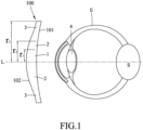
- the first embodiment of an optical lens 100 for vision correction is configured to be worn by a user in need of a vision correction in diopter (P) .
- the diopter (P) has a positive value and a negative value. It is known in the art that if the value of the diopter (P) of a lens is positive, it is used for correcting hyperopia or farsightedness, and if the value of the diopter (P) is negative, it is used for correcting myopia or nearsightedness.
- the optical lens 100 of this embodiment is a contact lens having an inner side surface 101 configured to contact the eye (E) of a user, an outer side surface 102 opposite to the inner side surface 101, and a plurality of image fusion areas between the inner and outer side surfaces 101, 102.
- the image fusion areas include a first image fusion area 1, a second image fusion area 2, and a third image fusion area 3.
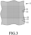
- the first image fusion area 1 is centered on a visual axis (L) of the eye (E), and includes a plurality of first dioptric portions 11 randomly arranged around the first image fusion area 1 and fused to have a first diopter (N).
- the first diopter (N) is obtained through an optical instrument testing, and is used to allow the eye to have a stable imaging through the first diopter (N) of the first image fusion area 1.
- the first dioptric portions 11 have concave and convex shapes of different diopter values.
- the first image fusion area 1 has a radius (r 1 ) with respect to the visual axis (L) ranging from 1 mm to 2.5 mm.
- Each of the first dioptric portions 11 has a diopter of N ⁇ 1 , where ⁇ 1 is a variable value ranging from 0.25D to 9.0D.
- the longest width (W11) of each of the first dioptric portions 11, 12 is smaller than 200 nanometers.
- the second image fusion area 2 is connected to and surrounds the first image fusion area 1, and includes a plurality of second dioptric portions 21 randomly arranged around the second image fusion area 2 and fused to have a second diopter (M).
- the second dioptric portions 21 have concave and convex shapes of different diopter values.
- is smaller than the absolute value of the second diopter
- the second image fusion area 2 has a radius (r 2 ) with respect to the visual axis (L) ranging from 1.5 mm to 4 mm.
- Each of the second dioptric portions 21 has a diopter of M ⁇ 2 , where ⁇ 2 is a variable value ranging from 0.25D to 12.0D.
- the longest width (W21) of each of the second dioptric portions 21 relative to the visual axis (L) is smaller than 200 nanometers.
- the third image fusion area 3 is connected to and surrounds the second image fusion area 2, and includes a plurality of third dioptric portions 31 randomly arranged around the third image fusion area 3 and fused to have a third diopter (O).
- the third dioptric portions 31 have concave and convex shapes of different diopter values.
- ranges between the absolute value of the first diopter
- the third image fusion area 3 has a radius (r 3 ) with respect to the visual axis (L) ranging from 2 mm to 8 mm.
- Each of the third dioptric portions 31 has a diopter of O ⁇ 3 , where ⁇ 3 is a variable value ranging from 0.25D to 12.0D.
- the longest width of each of the third dioptric portions 31 relative to the visual axis (L) is smaller than 200 nanometers.
- the first, second and third dioptric portions 11, 21, 31 are distributed around the outer side surface 102.
- Table 1 below demonstrates multiple experiments on the diopter configuration data range of the optical lens 100 of this disclosure.
- the relationship among the first diopter (N), the second diopter (M) and the third diopter (O) of optical lenses with different corrected diopters (P) are illustrated.
- the fused first diopter (N) and the fused second diopter (M) are configured gradually. That is, the diopters increase or decrease as the area gets closer to the visual axis (L). Whether or not to configure the third diopter (O) depends on whether the radius of the third image fusion area 3 with respect to the visual axis (L) is lower than 4 mm or not. If it is greater than 4 mm, because it is beyond the visible area of a normal eye, there is no need to fuse the third image fusion area 3. It is only necessary to continue a continuous concave surface along the second image fusion area 2, for example, configured a stable -8.0D. Through this, referring again to Figs.
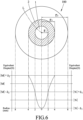
- a human eye vision imaging system forms a vision imaging correction visible area (S) located on the retina, and the eye (E) can directly make adjustment when looking far or near, so that the changes and compression deformations of the ciliary muscle and the lens of the refractive system can be minimized due to looking far or near, thereby reducing the feeling of eye fatigue.
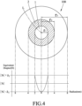
- Fig. 6 is a diagram taken from a use case of Table 2 in which the corrected diopter value is -2.0D.
- the first and second dioptric portions 11, 21 have negative diopters distributed from the visual axis (L).
- the maximum diopter value (N- ⁇ 1 ) of the first image fusion area 1 is 0, while the minimum diopter value (N+ ⁇ 1 ) thereof is -2.0D.
- the maximum diopter value (M- ⁇ 2 ) of the second image fusion area 2 is close to the minimum diopter value (N+ ⁇ 1 ) of the first image fusion area 1.
- the change in the diopters from the visual axis (L) outwardly is a continuous curve.
- an effect of vision image fusion is created, so that the human eye vision imaging system forms a vision imaging correction visible area (S) located on the retina.
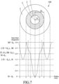
- Fig. 7 is a diagram taken from a use case of Table 3 in which the corrected diopter value is -2.0D.
- the second image fusion area 2 ranges from a radius of 2 mm to a radius of 3 mm with respect to the visual axis (L)
- the third image fusion area 3 ranges from a radius of 3 mm to a radius of 5 mm with respect to the visual axis (L).
- the maximum diopter value (N- ⁇ 1 ) of the first image fusion area 1 is 0, the minimum diopter value (N+ ⁇ 1 ) of the first image fusion area 1 is -2.0D, the maximum diopter value (M- ⁇ 2 ) of the second image fusion area 2 is close to the minimum diopter value (N+ ⁇ 1 ) of the first image fusion area 1, the maximum diopter value (O- ⁇ 3 ) of the third image fusion area 3 is -1.5D, and the minimum diopter value (O+ ⁇ 3 ) of the third image fusion area 3 is -2.5D.
- is smaller than the absolute value of the corrected diopter IPI
- is larger than the absolute value of the corrected diopter IPI
- is smaller than the absolute value of the second diopter
- is substantially equal to the absolute value of the corrected diopter
- the contact lens of this disclosure may extend outwardly to have a base curve of 8.0 mm.
- the optical structure of the contact lens of this disclosure is substantially equivalent to the aspheric monofocal contact lens.
- the optical lens of this disclosure can indeed be used for correcting different visual acuities in diopters.
- the present disclosure is currently conducting double blind and randomized clinical tests in Taipei Tzu Chi Hospital and National Taiwan University Hospital for wear of the optical lens 100 of this disclosure by different users. At present, it can be verified that the optical lens 100 of this disclosure can be used to correct vision, and will not produce the problem of image jump. Further, the diopter after fusion can indeed provide user correction of vision. Moreover, the clinical tests will verify whether further controlling of the myopia can be effected.
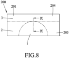
- the second embodiment of an optical lens 200 for vision correction is generally identical to the first embodiment, and differs in that the optical lens 200 of the second embodiment is an eyeglass lens.
- the optical lens 200 includes a lens body 201 having an inner side surface 202 proximate to the eye (E) (see Fig. 1 ), an outer side surface 203 opposite to the inner side surface 202, an upper part 204 between the inner and outer side surfaces 202, 203, and a lower part 205 opposite to the upper part 204.
- the first image fusion area 1 is located at the lower part 205
- the second image fusion area 2 is adjacently connected to the first image fusion area 1
- the third image fusion area 3 is adjacently connected to the second image fusion area 2 and is located at the upper part 204.
- the first, second and third dioptric portions 11, 21, 31 are distributed around the inner side surface 202. However, they may also be distributed on the outer side surface 201, and should not be limited to what is disclosed herein. Thus, the effect and purpose of the first embodiment can be similarly achieved using the second embodiment.
- the optical lens 100, 200 for vision correction can permit the human eye vision imaging system to form a visual imaging correction visible area (S) located on the retina.
- the eye (E) can directly make adjustment when looking far or near, thereby minimizing the changes and compression deformations of the ciliary muscle and the lens due to looking far or near.
- the feeling of eye fatigue can be reduced.
- the vision of the user can be constantly and stably controlled within the clear vision of external objects. Therefore, the object of this disclosure can indeed be achieved.
Landscapes
- Health & Medical Sciences (AREA)
- Ophthalmology & Optometry (AREA)
- Physics & Mathematics (AREA)
- General Health & Medical Sciences (AREA)
- General Physics & Mathematics (AREA)
- Optics & Photonics (AREA)
- Lenses (AREA)
- Eyeglasses (AREA)
- Prostheses (AREA)
Claims (4)
- Eine optische Linse (100, 200) zur Visuskorrektur, die Folgendes beinhaltet:einen ersten Bildfusionsbereich (1), der auf eine Sehachse (L) des Auges (E) eines Benutzers zentriert ist und eine Vielzahl von Abschnitten mit einer ersten Dioptrie (11) umfasst, die nach dem Zufallsprinzip um den ersten Bildfusionsbereich (1) angeordnet sind und so verschmolzen sind, dass der erste Bildfusionsbereich eine erste Dioptrie (N) aufweist; undeinen zweiten Bildfusionsbereich (2), der mit dem ersten Bildfusionsbereich (1) verbunden ist und diesen umgibt, wobei der zweite Bildfusionsbereich (2) eine Vielzahl von Abschnitten mit einer zweiten Dioptrie (21) umfasst, die nach dem Zufallsprinzip um den zweiten Bildfusionsbereich (2) angeordnet sind und so verschmolzen sind, dass der zweite Bildfusionsbereich (2) eine zweite Dioptrie (M) aufweist;wobei der absolute Wert der ersten Dioptrie |N| kleiner als der absolute Wert der zweiten Dioptrie IMI ist und die längste Breite von jedem der Abschnitte mit einer ersten und einer zweiten Dioptrie (11,21) relativ zu der Sehachse (L) kleiner als 200 Nanometer ist; unddadurch gekennzeichnet, dass jeder der Abschnitte mit einer ersten Dioptrie (11) eine Dioptrie von N ± δ1 aufweist, wo δ1 ein variabler Wert im Bereich von 0,25 D bis 9,0 D ist, und jeder der Abschnitte mit einer zweiten Dioptrie (21) eine Dioptrie von M ± δ2 aufweist, wo δ2 ein variabler Wert im Bereich von 0,25 D bis 12,0 D ist.
- Optische Linse (100, 200) gemäß Anspruch 1, die ferner einen dritten Bildfusionsbereich (3) beinhaltet, der mit dem zweiten Bildfusionsbereich (2) verbunden ist und diesen umgibt, wobei der dritte Bildfusionsbereich (3) eine Vielzahl von Abschnitten mit einer dritten Dioptrie (31) umfasst, die nach dem Zufallsprinzip um den dritten Bildfusionsbereich (3) angeordnet sind und verschmolzen sind, sodass sie eine dritte Dioptrie (O) aufweisen, wobei jeder der Abschnitte mit einer dritten Dioptrie (31) eine Dioptrie von O ± δ3 aufweist, wo δ3 ein variabler Wert im Bereich von 0,25 D bis 12,0 D ist, und die dritte Dioptrie |O| im Bereich zwischen der ersten Dioptrie |N| und der zweiten Dioptrie IMI liegt.
- Optische Linse (100) gemäß Anspruch 2, wobei die optische Linse (100) eine Kontaktlinse ist, der erste Bildfusionsbereich (1) einen Radius (r1) bezüglich der Sehachse (L) im Bereich von 1 mm bis 2,5 mm aufweist, der zweite Bildfusionsbereich (2) einen Radius (r2) bezüglich der Sehachse (L) im Bereich von 1,5 mm bis 4 mm aufweist und der dritte Bildfusionsbereich (3) einen Radius (r3) bezüglich der Sehachse (L) im Bereich von 2 mm bis 8 mm aufweist.
- Optische Linse (100) gemäß Anspruch 3, die ferner eine innere Seitenfläche (101), die dazu ausgelegt ist, mit dem Auge (E) in Kontakt zu kommen, und eine äußere Seitenfläche (102), die gegenüber der inneren Seitenfläche (101) liegt, beinhaltet und wobei die Abschnitte mit einer ersten, zweiten und dritten Dioptrie (1, 2, 3) um eine von der äußeren (102) und inneren (101) Seitenfläche verteilt sind.
Applications Claiming Priority (2)
| Application Number | Priority Date | Filing Date | Title |
|---|---|---|---|
| TW106129178A TWI636296B (zh) | 2017-08-28 | 2017-08-28 | 視力矯正用光學鏡片 |
| PCT/IB2018/056415 WO2019043531A1 (en) | 2017-08-28 | 2018-08-24 | OPTICAL LENS FOR CORRECTING VISION |
Publications (4)
| Publication Number | Publication Date |
|---|---|
| EP3676659A1 EP3676659A1 (de) | 2020-07-08 |
| EP3676659A4 EP3676659A4 (de) | 2021-05-26 |
| EP3676659B1 true EP3676659B1 (de) | 2023-11-01 |
| EP3676659C0 EP3676659C0 (de) | 2023-11-01 |
Family
ID=64453121
Family Applications (1)
| Application Number | Title | Priority Date | Filing Date |
|---|---|---|---|
| EP18851786.6A Active EP3676659B1 (de) | 2017-08-28 | 2018-08-24 | Optische linse zur sichtkorrektur |
Country Status (9)
| Country | Link |
|---|---|
| US (1) | US10802296B2 (de) |
| EP (1) | EP3676659B1 (de) |
| JP (1) | JP6938679B2 (de) |
| KR (1) | KR102217779B1 (de) |
| CN (1) | CN109426007B (de) |
| AU (1) | AU2018322975B2 (de) |
| ES (1) | ES2966914T3 (de) |
| TW (1) | TWI636296B (de) |
| WO (1) | WO2019043531A1 (de) |
Families Citing this family (9)
| Publication number | Priority date | Publication date | Assignee | Title |
|---|---|---|---|---|
| EP3761104A1 (de) * | 2019-07-04 | 2021-01-06 | Essilor International | Optisches system |
| JP2022542164A (ja) * | 2019-07-29 | 2022-09-29 | 株式会社メニコン | メタオプティクスを含む眼科用レンズを形成するためのシステム及び方法 |
| JP7541882B2 (ja) | 2020-09-18 | 2024-08-29 | ホヤ レンズ タイランド リミテッド | 眼鏡レンズ及びその設計方法 |
| JP2023550996A (ja) * | 2020-11-27 | 2023-12-06 | エシロール・アンテルナシオナル | レンズ要素 |
| CN114114715B (zh) * | 2021-11-22 | 2024-03-22 | 江苏全真光学科技股份有限公司 | 一种屈光度可变的防近视变色眼镜 |
| JP7692930B2 (ja) * | 2021-12-27 | 2025-06-16 | ペガヴィジョン コーポレーション | 光学レンズ |
| TWI827339B (zh) * | 2022-11-04 | 2023-12-21 | 黃上人 | 兒童近視控制隱形眼鏡 |
| CN115903266B (zh) * | 2022-11-22 | 2025-07-25 | 黄上人 | 儿童近视控制隐形眼镜 |
| TWI874287B (zh) * | 2024-04-30 | 2025-02-21 | 視陽光學股份有限公司 | 近視控制隱形眼鏡 |
Family Cites Families (24)
| Publication number | Priority date | Publication date | Assignee | Title |
|---|---|---|---|---|
| EP0201231A3 (de) * | 1985-05-03 | 1989-07-12 | THE COOPER COMPANIES, INC. (formerly called CooperVision, Inc.) | Verfahren zur Behandlung von Alterssichtigkeit mit konzentrischen Bifokalkontaktlinsen |
| US4752123A (en) * | 1985-11-19 | 1988-06-21 | University Optical Products Co. | Concentric bifocal contact lens with two distance power regions |
| DE3854782T2 (de) * | 1987-06-01 | 1996-05-02 | Valdemar Portney | Ophthalmische linse mit mehreren brennpunkten |
| JPH02196211A (ja) * | 1989-01-26 | 1990-08-02 | Mieele Kk | 眼鏡用レンズ |
| US6288846B1 (en) * | 1999-09-24 | 2001-09-11 | Arizona Carbon Foil Co., Inc. | Variable focal-length lens assembly |
| JP2003029216A (ja) * | 2001-07-10 | 2003-01-29 | Yoshio Yokoyama | 老眼鏡および老眼用コンタクトレンズ |
| EP2527908B1 (de) * | 2004-10-25 | 2019-03-20 | Johnson & Johnson Surgical Vision, Inc. | Ophthalmische Linse mit mehreren diffraktiven Zonen |
| FR2888951B1 (fr) * | 2005-07-20 | 2008-02-08 | Essilor Int | Composant optique pixellise aleatoirement, son procede de fabrication, et son utilisation dans la fabrication d'un element optique transparent |
| AU2006301940B2 (en) | 2005-10-12 | 2012-03-29 | Carl Zeiss Vision Australia Holdings Limited | Ophthalmic lens element for myopia correction |
| US7717556B1 (en) * | 2006-07-05 | 2010-05-18 | Jon Scott Walker | Visual enhancement lens and associated methods |
| JP2008090204A (ja) * | 2006-10-05 | 2008-04-17 | Miki:Kk | 眼鏡用レンズ |
| US20080297721A1 (en) * | 2007-05-29 | 2008-12-04 | Amitava Gupta | Lens designs for treating asthenopia caused by visual defects |
| TWI487516B (zh) | 2007-08-22 | 2015-06-11 | Novartis Ag | 老花眼的治療系統 |
| US20110040377A1 (en) | 2008-02-05 | 2011-02-17 | Laser Energies, Inc. | Compound micro lens implant |
| US8292953B2 (en) * | 2008-10-20 | 2012-10-23 | Amo Groningen B.V. | Multifocal intraocular lens |
| US20120212696A1 (en) * | 2011-01-27 | 2012-08-23 | Pixeloptics, Inc. | Variable optical element comprising a liquid crystal alignment layer |
| TWI516830B (zh) * | 2012-05-07 | 2016-01-11 | 星歐光學股份有限公司 | 視力控制隱形眼鏡 |
| US20150153588A1 (en) * | 2012-07-13 | 2015-06-04 | University Of Florida Research Foundation, Inc. | Contact lens with spatially heterogenous surface patterns for improved lubricity |
| US9658469B2 (en) * | 2013-03-15 | 2017-05-23 | Johnson & Johnson Vision Care, Inc. | Ophthalmic devices incorporating metasurface elements |
| ES2529378B1 (es) * | 2013-06-10 | 2015-12-18 | Universitat De València | Lente oftálmica multifocal y procedimiento para su obtención, mejorada |
| US9625739B2 (en) | 2014-08-20 | 2017-04-18 | Johnson & Johnson Vision Care, Inc. | Pupil size-independent lens design and method for preventing and/or slowing myopia progression |
| US10268050B2 (en) * | 2015-11-06 | 2019-04-23 | Hoya Lens Thailand Ltd. | Spectacle lens |
| US11567346B2 (en) * | 2016-02-10 | 2023-01-31 | Visioneering Technologies, Inc. | Induced aperture lens and method |
| CN106950718B (zh) * | 2017-04-27 | 2023-06-02 | 陈奎 | 视力矫正双镜片组中的等距不等极差变焦透镜直纹单片 |
-
2017
- 2017-08-28 TW TW106129178A patent/TWI636296B/zh active
- 2017-10-12 CN CN201710948263.9A patent/CN109426007B/zh active Active
-
2018
- 2018-07-20 US US16/040,812 patent/US10802296B2/en active Active
- 2018-08-24 WO PCT/IB2018/056415 patent/WO2019043531A1/en not_active Ceased
- 2018-08-24 KR KR1020197037825A patent/KR102217779B1/ko active Active
- 2018-08-24 AU AU2018322975A patent/AU2018322975B2/en active Active
- 2018-08-24 JP JP2019562543A patent/JP6938679B2/ja active Active
- 2018-08-24 ES ES18851786T patent/ES2966914T3/es active Active
- 2018-08-24 EP EP18851786.6A patent/EP3676659B1/de active Active
Also Published As
| Publication number | Publication date |
|---|---|
| KR102217779B1 (ko) | 2021-02-19 |
| JP6938679B2 (ja) | 2021-09-22 |
| TWI636296B (zh) | 2018-09-21 |
| KR20200008164A (ko) | 2020-01-23 |
| TW201913185A (zh) | 2019-04-01 |
| WO2019043531A1 (en) | 2019-03-07 |
| CN109426007B (zh) | 2021-05-04 |
| US20190064542A1 (en) | 2019-02-28 |
| EP3676659A1 (de) | 2020-07-08 |
| US10802296B2 (en) | 2020-10-13 |
| EP3676659C0 (de) | 2023-11-01 |
| CN109426007A (zh) | 2019-03-05 |
| AU2018322975B2 (en) | 2020-12-17 |
| JP2020527735A (ja) | 2020-09-10 |
| AU2018322975A1 (en) | 2020-01-02 |
| EP3676659A4 (de) | 2021-05-26 |
| ES2966914T3 (es) | 2024-04-25 |
Similar Documents
| Publication | Publication Date | Title |
|---|---|---|
| EP3676659B1 (de) | Optische linse zur sichtkorrektur | |
| KR102341449B1 (ko) | 근시 진행을 예방하고/하거나 늦추기 위한 다초점 렌즈 설계 및 방법 | |
| AU2007258008B2 (en) | Means for controlling the progression of myopia | |
| EP2778749B1 (de) | Presbyopie-Linse mit Pupillengrößenkorrektur auf Grundlage des Brechungsfehlergrads | |
| AU2002340292B2 (en) | Eyeglass having variable index layer | |
| KR20170080618A (ko) | 근시 진행 억제를 위한 단초점 및 다초점 렌즈를 수반하는 시스템 및 방법 | |
| AU2014208267B1 (en) | Toric Lens | |
| JP2017090919A (ja) | 最適化性能を有する先端を切った並進型コンタクトレンズ及び設計方法 | |
| TWI686640B (zh) | 具最佳效能之隱形眼鏡及設計方法 | |
| CN110376758B (zh) | 一种加强多焦点聚氨酯镜片的制造方法 | |
| US20180024380A1 (en) | Progressive multifocal contact lens and producing method thereof | |
| CN112204456A (zh) | 考虑美容和功效的光致变色软性接触镜片 | |
| KR102659759B1 (ko) | 향상된 편안함을 갖는 회전 안정화된 콘택트 렌즈 및 최적화의 방법 | |
| EP1331505B1 (de) | Kontaktlinse und Entwurfsverfahren für Kontaktlinsen | |
| JP2005062805A (ja) | コンタクトレンズおよびその形成方法 | |
| EP4266116A1 (de) | Brillenglas zur optimierten kontrolle von myopie | |
| KR101228458B1 (ko) | 안과용 렌즈 | |
| KR20250123672A (ko) | 근시 제어를 위한 안과용 렌즈 | |
| WO2025184865A1 (en) | Spectacle lens and kit | |
| US11156854B2 (en) | Progressive ophthalmic lens | |
| HK40005407B (zh) | 视力矫正用光学镜片 | |
| Jalie | Progressive power lenses-part 5 | |
| NZ628191B (en) | Toric Lens |
Legal Events
| Date | Code | Title | Description |
|---|---|---|---|
| STAA | Information on the status of an ep patent application or granted ep patent |
Free format text: STATUS: THE INTERNATIONAL PUBLICATION HAS BEEN MADE |
|
| PUAI | Public reference made under article 153(3) epc to a published international application that has entered the european phase |
Free format text: ORIGINAL CODE: 0009012 |
|
| STAA | Information on the status of an ep patent application or granted ep patent |
Free format text: STATUS: REQUEST FOR EXAMINATION WAS MADE |
|
| 17P | Request for examination filed |
Effective date: 20191113 |
|
| AK | Designated contracting states |
Kind code of ref document: A1 Designated state(s): AL AT BE BG CH CY CZ DE DK EE ES FI FR GB GR HR HU IE IS IT LI LT LU LV MC MK MT NL NO PL PT RO RS SE SI SK SM TR |
|
| AX | Request for extension of the european patent |
Extension state: BA ME |
|
| DAV | Request for validation of the european patent (deleted) | ||
| DAX | Request for extension of the european patent (deleted) | ||
| A4 | Supplementary search report drawn up and despatched |
Effective date: 20210422 |
|
| RIC1 | Information provided on ipc code assigned before grant |
Ipc: G02C 7/06 20060101AFI20210416BHEP Ipc: G02C 7/02 20060101ALI20210416BHEP Ipc: G02C 7/04 20060101ALI20210416BHEP |
|
| GRAP | Despatch of communication of intention to grant a patent |
Free format text: ORIGINAL CODE: EPIDOSNIGR1 |
|
| STAA | Information on the status of an ep patent application or granted ep patent |
Free format text: STATUS: GRANT OF PATENT IS INTENDED |
|
| INTG | Intention to grant announced |
Effective date: 20230602 |
|
| GRAS | Grant fee paid |
Free format text: ORIGINAL CODE: EPIDOSNIGR3 |
|
| GRAA | (expected) grant |
Free format text: ORIGINAL CODE: 0009210 |
|
| STAA | Information on the status of an ep patent application or granted ep patent |
Free format text: STATUS: THE PATENT HAS BEEN GRANTED |
|
| AK | Designated contracting states |
Kind code of ref document: B1 Designated state(s): AL AT BE BG CH CY CZ DE DK EE ES FI FR GB GR HR HU IE IS IT LI LT LU LV MC MK MT NL NO PL PT RO RS SE SI SK SM TR |
|
| REG | Reference to a national code |
Ref country code: GB Ref legal event code: FG4D |
|
| REG | Reference to a national code |
Ref country code: CH Ref legal event code: EP |
|
| REG | Reference to a national code |
Ref country code: IE Ref legal event code: FG4D |
|
| REG | Reference to a national code |
Ref country code: DE Ref legal event code: R096 Ref document number: 602018060552 Country of ref document: DE |
|
| U01 | Request for unitary effect filed |
Effective date: 20231106 |
|
| U07 | Unitary effect registered |
Designated state(s): AT BE BG DE DK EE FI FR IT LT LU LV MT NL PT SE SI Effective date: 20231110 |
|
| PG25 | Lapsed in a contracting state [announced via postgrant information from national office to epo] |
Ref country code: GR Free format text: LAPSE BECAUSE OF FAILURE TO SUBMIT A TRANSLATION OF THE DESCRIPTION OR TO PAY THE FEE WITHIN THE PRESCRIBED TIME-LIMIT Effective date: 20240202 |
|
| PG25 | Lapsed in a contracting state [announced via postgrant information from national office to epo] |
Ref country code: IS Free format text: LAPSE BECAUSE OF FAILURE TO SUBMIT A TRANSLATION OF THE DESCRIPTION OR TO PAY THE FEE WITHIN THE PRESCRIBED TIME-LIMIT Effective date: 20240301 |
|
| REG | Reference to a national code |
Ref country code: ES Ref legal event code: FG2A Ref document number: 2966914 Country of ref document: ES Kind code of ref document: T3 Effective date: 20240425 |
|
| PG25 | Lapsed in a contracting state [announced via postgrant information from national office to epo] |
Ref country code: IS Free format text: LAPSE BECAUSE OF FAILURE TO SUBMIT A TRANSLATION OF THE DESCRIPTION OR TO PAY THE FEE WITHIN THE PRESCRIBED TIME-LIMIT Effective date: 20240301 Ref country code: GR Free format text: LAPSE BECAUSE OF FAILURE TO SUBMIT A TRANSLATION OF THE DESCRIPTION OR TO PAY THE FEE WITHIN THE PRESCRIBED TIME-LIMIT Effective date: 20240202 |
|
| PG25 | Lapsed in a contracting state [announced via postgrant information from national office to epo] |
Ref country code: RS Free format text: LAPSE BECAUSE OF FAILURE TO SUBMIT A TRANSLATION OF THE DESCRIPTION OR TO PAY THE FEE WITHIN THE PRESCRIBED TIME-LIMIT Effective date: 20231101 Ref country code: PL Free format text: LAPSE BECAUSE OF FAILURE TO SUBMIT A TRANSLATION OF THE DESCRIPTION OR TO PAY THE FEE WITHIN THE PRESCRIBED TIME-LIMIT Effective date: 20231101 Ref country code: NO Free format text: LAPSE BECAUSE OF FAILURE TO SUBMIT A TRANSLATION OF THE DESCRIPTION OR TO PAY THE FEE WITHIN THE PRESCRIBED TIME-LIMIT Effective date: 20240201 Ref country code: HR Free format text: LAPSE BECAUSE OF FAILURE TO SUBMIT A TRANSLATION OF THE DESCRIPTION OR TO PAY THE FEE WITHIN THE PRESCRIBED TIME-LIMIT Effective date: 20231101 |
|
| U20 | Renewal fee for the european patent with unitary effect paid |
Year of fee payment: 7 Effective date: 20240606 |
|
| PG25 | Lapsed in a contracting state [announced via postgrant information from national office to epo] |
Ref country code: CZ Free format text: LAPSE BECAUSE OF FAILURE TO SUBMIT A TRANSLATION OF THE DESCRIPTION OR TO PAY THE FEE WITHIN THE PRESCRIBED TIME-LIMIT Effective date: 20231101 |
|
| PG25 | Lapsed in a contracting state [announced via postgrant information from national office to epo] |
Ref country code: SK Free format text: LAPSE BECAUSE OF FAILURE TO SUBMIT A TRANSLATION OF THE DESCRIPTION OR TO PAY THE FEE WITHIN THE PRESCRIBED TIME-LIMIT Effective date: 20231101 |
|
| PG25 | Lapsed in a contracting state [announced via postgrant information from national office to epo] |
Ref country code: SM Free format text: LAPSE BECAUSE OF FAILURE TO SUBMIT A TRANSLATION OF THE DESCRIPTION OR TO PAY THE FEE WITHIN THE PRESCRIBED TIME-LIMIT Effective date: 20231101 Ref country code: SK Free format text: LAPSE BECAUSE OF FAILURE TO SUBMIT A TRANSLATION OF THE DESCRIPTION OR TO PAY THE FEE WITHIN THE PRESCRIBED TIME-LIMIT Effective date: 20231101 Ref country code: CZ Free format text: LAPSE BECAUSE OF FAILURE TO SUBMIT A TRANSLATION OF THE DESCRIPTION OR TO PAY THE FEE WITHIN THE PRESCRIBED TIME-LIMIT Effective date: 20231101 |
|
| REG | Reference to a national code |
Ref country code: DE Ref legal event code: R097 Ref document number: 602018060552 Country of ref document: DE |
|
| PLBE | No opposition filed within time limit |
Free format text: ORIGINAL CODE: 0009261 |
|
| STAA | Information on the status of an ep patent application or granted ep patent |
Free format text: STATUS: NO OPPOSITION FILED WITHIN TIME LIMIT |
|
| 26N | No opposition filed |
Effective date: 20240802 |
|
| REG | Reference to a national code |
Ref country code: CH Ref legal event code: PL |
|
| PG25 | Lapsed in a contracting state [announced via postgrant information from national office to epo] |
Ref country code: MC Free format text: LAPSE BECAUSE OF FAILURE TO SUBMIT A TRANSLATION OF THE DESCRIPTION OR TO PAY THE FEE WITHIN THE PRESCRIBED TIME-LIMIT Effective date: 20231101 Ref country code: CH Free format text: LAPSE BECAUSE OF NON-PAYMENT OF DUE FEES Effective date: 20240831 |
|
| PGFP | Annual fee paid to national office [announced via postgrant information from national office to epo] |
Ref country code: GB Payment date: 20250602 Year of fee payment: 8 |
|
| U20 | Renewal fee for the european patent with unitary effect paid |
Year of fee payment: 8 Effective date: 20250616 |
|
| PG25 | Lapsed in a contracting state [announced via postgrant information from national office to epo] |
Ref country code: IE Free format text: LAPSE BECAUSE OF NON-PAYMENT OF DUE FEES Effective date: 20240824 |
|
| PGFP | Annual fee paid to national office [announced via postgrant information from national office to epo] |
Ref country code: ES Payment date: 20250916 Year of fee payment: 8 |
|
| PG25 | Lapsed in a contracting state [announced via postgrant information from national office to epo] |
Ref country code: RO Free format text: LAPSE BECAUSE OF FAILURE TO SUBMIT A TRANSLATION OF THE DESCRIPTION OR TO PAY THE FEE WITHIN THE PRESCRIBED TIME-LIMIT Effective date: 20231101 |
|
| PG25 | Lapsed in a contracting state [announced via postgrant information from national office to epo] |
Ref country code: CY Free format text: LAPSE BECAUSE OF FAILURE TO SUBMIT A TRANSLATION OF THE DESCRIPTION OR TO PAY THE FEE WITHIN THE PRESCRIBED TIME-LIMIT; INVALID AB INITIO Effective date: 20180824 |
|
| PG25 | Lapsed in a contracting state [announced via postgrant information from national office to epo] |
Ref country code: HU Free format text: LAPSE BECAUSE OF FAILURE TO SUBMIT A TRANSLATION OF THE DESCRIPTION OR TO PAY THE FEE WITHIN THE PRESCRIBED TIME-LIMIT; INVALID AB INITIO Effective date: 20180824 |