EP3676856B1 - Einschlussgebinde mit fass zur aufnahme von radioaktivem sonderabfall - Google Patents
Einschlussgebinde mit fass zur aufnahme von radioaktivem sonderabfall Download PDFInfo
- Publication number
- EP3676856B1 EP3676856B1 EP18849818.2A EP18849818A EP3676856B1 EP 3676856 B1 EP3676856 B1 EP 3676856B1 EP 18849818 A EP18849818 A EP 18849818A EP 3676856 B1 EP3676856 B1 EP 3676856B1
- Authority
- EP
- European Patent Office
- Prior art keywords
- cask
- containment vessel
- side wall
- drum
- containment
- Prior art date
- Legal status (The legal status is an assumption and is not a legal conclusion. Google has not performed a legal analysis and makes no representation as to the accuracy of the status listed.)
- Active
Links
Images



Classifications
-
- G—PHYSICS
- G21—NUCLEAR PHYSICS; NUCLEAR ENGINEERING
- G21F—PROTECTION AGAINST X-RADIATION, GAMMA RADIATION, CORPUSCULAR RADIATION OR PARTICLE BOMBARDMENT; TREATING RADIOACTIVELY CONTAMINATED MATERIAL; DECONTAMINATION ARRANGEMENTS THEREFOR
- G21F5/00—Transportable or portable shielded containers
- G21F5/005—Containers for solid radioactive wastes, e.g. for ultimate disposal
-
- G—PHYSICS
- G21—NUCLEAR PHYSICS; NUCLEAR ENGINEERING
- G21F—PROTECTION AGAINST X-RADIATION, GAMMA RADIATION, CORPUSCULAR RADIATION OR PARTICLE BOMBARDMENT; TREATING RADIOACTIVELY CONTAMINATED MATERIAL; DECONTAMINATION ARRANGEMENTS THEREFOR
- G21F5/00—Transportable or portable shielded containers
- G21F5/06—Details of, or accessories to, the containers
- G21F5/08—Shock-absorbers, e.g. impact buffers for containers
-
- G—PHYSICS
- G21—NUCLEAR PHYSICS; NUCLEAR ENGINEERING
- G21F—PROTECTION AGAINST X-RADIATION, GAMMA RADIATION, CORPUSCULAR RADIATION OR PARTICLE BOMBARDMENT; TREATING RADIOACTIVELY CONTAMINATED MATERIAL; DECONTAMINATION ARRANGEMENTS THEREFOR
- G21F5/00—Transportable or portable shielded containers
- G21F5/06—Details of, or accessories to, the containers
- G21F5/12—Closures for containers; Sealing arrangements
Definitions
- the embodiments of the present disclosure generally relate to safely transporting and storing drums that contain radioactive hazardous waste.
- EP 1 205 940 discloses a containment cask for safely transporting and storing radioactive hazardous waste without a payload liner.
- EP 0 036 954 discloses a payload liner inside a container and mounted to the container wall by tension rods.
- Embodiments of containment casks and methods are provided for safely transporting and storing drums that contain radioactive hazardous waste.
- the invention is a containment cask for safely transporting and storing radioactive hazardous waste in a dry air environment.
- the cask comprises a single drum containing the radioactive hazardous waste, a sealed and shielded containment vessel containing the drum, and an outer container as defined in claim 1.
- the outer container can take a plurality of forms. It can be in the form of an outer shield vessel (OSV) made from iron to provide further shielding. This outer container is appropriate for a drum having higher activity waste.
- the outer container can also be in the form of an overpack assembly that adds protection for hypothetical accident conditions (e.g., free drop, puncture, and fire), but adds little in terms of shielding. This outer container is appropriate for a drum having lower activity waste.
- OSV outer shield vessel
- CCV common containment vessel
- radioactive hazardous waste including but not limited to, non-compliant remote handled transuranic (RH-TRU) waste (e.g., RH-TRU waste containing items that are not permitted by the waste isolation pilot plate (WIPP) acceptance criteria, such as aerosol cans, small liquid containers, etc.), Canada deuterium uranium (CANDU) waste, radioactive debris, experimental spent nuclear fuel, irradiated fissile materials, nuclear fuel debris, high level waste (HLW), greater than Class C waste (GTCC), etc.
- the drum 16 can be any one of the following: a U.S. standard 110-gallon (i.e. approximately 416 I) drum 16a ( FIG. 9A ), 85-gallon (i.e.
- the design of the containment cask 10 is simple and low cost.
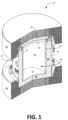
- the first embodiment of the containment cask 10 is designed with more shielding than the second embodiment, which will be described in detail later in this document, in order to handle drums having higher radioactive waste content.
- the CCV 14 has an elongated cylindrical body 18 extending between a top end and a bottom end.
- the CCV body includes a cylindrical side wall 25, a planar bottom plate 22 at the bottom end and welded to the side wall 25, a flared bolt flange 23 with an open top welded to the side wall 25 at the top end, and a circular planar lid 24 mounted to the top of the flared bolt flange 23 and over the open top.
- the CCV 14 is made from stainless steel and is the primary shielding mechanism for the contained drum 16. When in use for transport and storage, the CCV 14 is in a completely sealed configuration.
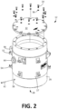
- FIG. 2 is an exploded view of the OSV 12.
- the OSV 12 has an elongated cylindrical OSV body 26 extending between a top end and a bottom end.
- the OSV body 26 includes a side wall 27, a planar bottom plate 28 at the bottom end that is integral to the side wall 27, and a circular planar lid 32 mounted to the side wall 27 at the top end and over the open top of the OSV 12.
- the OSV body 26 defines an interior region that contains the CCV 14 having the single drum 16 containing the radioactive hazardous waste.
- the OSV 12 is not a pressure maintaining assembly, but merely a structure to protect the CCD 14 from external events, such as potential drops, punctures, fire, etc.
- the OSV 12 comprises supplemental shielding required to reduce the external radiation dose rates to acceptable levels.
- the side wall 27, bottom plate 28, and lid 32 of the OSV 12 is made from ductile cast iron.
- the thickness of the iron side wall 27 is (a) about 178 mm (7 inches) between the impact limiters 56, (b) about 165 mm (6.5 inches) where the impact limiters 56 overhang the ends of the OSV, and (c) about 152 mm (6 inches) at the bottom end.
- the containment cask 10 can be used to transport and store a drum 16 having RH-TRU waste and/or irradiated fuel waste.
- RH-TRU and irradiated fuel waste can exhibit a decay heat of no greater than 200 Watts and 1500 Watts, respectively.
- the lid 32 at the top end is bolted to the OSV body 26 via a plurality of alloy steel bolts 34 with steel washers 36 and an elastomeric gasket weather seal to prevent water intrusion. Alignment pins are also used to facilitate OSV lid alignment and installation operations.
- the OSV 12 includes one or more drain ports 38, preferably one, with corresponding drain port plugs 42 for enabling and disabling drainage.
- the drain port 38 is provided to allow the OSV cavity to be checked for the presence of liquids, and drained if needed, during storage or site operations.
- the drain port may also be used for continuous monitoring, if required by the site and/or the governing regulations.
- the drain port 38 can enable free draining, when the containment cask 10 is in storage mode, to prevent trapping of water in the interior region of the OSV 12 that is outside of the sealed CCV 12.
- a plurality of diametrically opposed lifting trunnions 44 are positioned on opposing sides and extend outwardly from the surface of the OSV body 26 to enable vertical handling of the containment cask 10 and securing of the containment cask 10.
- the lifting trunnions 44 are cast into the OSV body, are a simple lift yoke design that can be operated without special equipment, and comply with ANSI-N14.6 industry standards.
- the lifting trunnions 44 can also be used to tie down the containment cask 10 for transport.
- a plurality of tie-down lugs 46 are also positioned to extend outwardly from the surface of the OSV body 26 to enable the containment cask 10 to be secured.
- the tiedown lugs 46 enable the containment cask 10 to be secured to a trailer bed. Because of the light weight of the containment cask 10 (i.e., CCV weight of between approximately 1.202 kg (2650 lb.) and approximately 2.812 kg (6200 lb.) and gross cask weight of between approximately 11.839 kg (26,100 lb.) and approximately 13.608 kg (30,000 lb.)), up to three of the containment casks 10 can be shipped per road shipment, and the tie down arms 46 can be used to secure them to a trailer bed.
- CCV weight of between approximately 1.202 kg (2650 lb.) and approximately 2.812 kg (6200 lb.)
- gross cask weight of between approximately 11.839 kg (26,100 lb.) and approximately 13.608 kg (30,000 lb.)
- the OSV 12 includes a plurality of upper impact limiter attachment lugs 52 extending outwardly from the OSV body 26 so that an upper impact limiter 56 can be situated at the top end of the OSV 12.
- the OSV 12 further includes a plurality of lower impact limiter attachment lugs 56 extending outwardly from the OSV body 26 so that a lower impact limiter 56 can be situated at the bottom end of the OSV 12.
- each of the upper and lower impact limiters 56 are identical in construction.
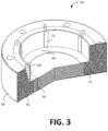
- each impact limiter 56 has a pocket on the inside that fits over the respective end of the OSV 12.
- Each impact limiter 56 has a stainless steel shell 58 encapsulating a rigid polyurethane foam 62. In the preferred embodiment, the shell has a thickness of about 0.075 inches.
- Each impact limiter 56 includes a plurality of attachment lugs 64 that engage and attach to attachment lugs 54 ( FIG. 2 ) associated with the OSV 12 using preferably T-bolt type connections.
- a drain tube 66 enables water to exit the annular gap region between the bottom impact limiter 56 and the OSV 12. For the top impact limiter 56, the drain tube 66 is capped to prevent water intrusion.
- a bottom rub ring 68 and a plurality of radial rub strips 72 are designed to engage the outside of the OSV 12.
- a shear ring 74 provides a shearing effect, if needed.
- Other suitable types of impact limiters are known and could be utilized instead of the one associated with the preferred embodiment.
- the containment cask 10 measures about 74.5 inches in diameter and about 84.5 inches in vertical height. Moreover, the robust design enables storage of the containment cask 10 in an existing building or outdoors.
- FIG. 4 is a perspective view of the containment cask 10'.
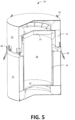
- FIG. 5 is a perspective view of the second embodiment with cutaway showing an unshielded overpack assembly 76 (outer container) that contains the CCV 14 ( FIG. 1 ) that is designed to contain a single drum 16 ( FIG.
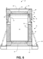
- FIG. 6 is a cross sectional view of the containment cask 10'.
- the overpack assembly 76 generally provides minimal supplemental shielding to assist with the primary shielding provided by the CCV 14.
- the overpack assembly 76 has a cylindrical base assembly 75 that is covered by a cylindrical lid assembly 78.
- the lid assembly 78 is bolted to the base assembly 75 via a plurality of equally spaced bolts 80 to secure the CCV 18 within its internal cavity.
- the base assembly 75 and lid assembly 78 are generally made of stainless steel shells that are filled with rigid polyurethane foam. There is flexibility in connection with the shielding. Shielding inserts can be optimized for different contents, eliminating the need to repackage some drums that have non-compliant TRU waste and thereby resulting in fewer shipments.
- the lid assembly 78 has a plurality of lifting tabs 81 to enable vertical handling of the lid assembly 78 and loaded package 10' using standard rigging.
- the base assembly 75 is equipped with a plurality of tie down arms 82 to enable the overpack assembly 76 (and containment cask 10') to be secured to a support structure 83. Because of the light weight of the packaging 10' and contents (i.e., CCV weight of about 1.406 kg (3100 lb.) and gross cask weight between about 2.722 kg (6,000 lb.) to 3.716 kg (8,200 lb.)), up to ten of the containment casks 10' can be shipped per road shipment, and the tie down arms 82 can be used to secure them to a trailer bed.
- the overpack assembly 76 when assembled, has an elongated cylindrical body extending between a top end and a bottom end. There is a planar bottom plate 83 at the bottom end that is welded to the body of the base assembly 75, and there is a planar top plate 84 at the top end that is welded to the body of the lid assembly 78.
- the sides of the base assembly 75 has outer and inner stainless steel shells 75a, 75b with side foam 85 between them.
- the sides of the lid assembly 78 also has outer and inner stainless steel shells 78a, 78b with side foam 86 between them.
- the bottom end of the base assembly 75 includes corner foam 87 and center foam 87.
- a thermal spider may also be situated in the center foam 87 for heat dissipation.
- the top end of the lid assembly 78 includes corner foam 88 and center foam 89.
- the thickness of the outer and inner shells are designed for optimal crushing properties, and in the preferred embodiment, are 3/16 inches and 14 gauge, respectively.
- the containment cask 10 measures about 1,19 m (47 inches) in diameter and about 1,63 m (64.5 inches) in vertical height.
- FIG. 7 is a perspective view and FIG. 8 is an exploded view of the CCV 14 (of FIGs. 1 and 4 ) that is stored within the first and second embodiments of the containment cask 10, 10'.
- the CCV 14 has an elongated cylindrical body 18 extending between a top end and a bottom end.
- the CCV body includes a cylindrical side wall 18, a planar bottom plate 22 at the bottom end and welded to the side wall 18, a flared bolt flange 23 with an open top welded to the side wall 18 at the top end, and a circular planar lid 24 mounted to the top of the flared bolt flange 23 and over the open top.
- the drum 16 can have a fissile gram equivalent (FGE; i.e., grams of plutonium 239) up to 390.
- FGE fissile gram equivalent
- the lid 24 is mounted to the flared bolt flange 23 via a plurality of captured closure bolts 99 with corresponding washers 101.
- the captured bolts 99 facilitate remote lid installation and removal operations that are required for certain payloads.
- Alignment pins are used to facilitate CCV lid alignment and installation operations.
- a plurality of spaced-apart, concentric O-rings 102 are situated between the lid 24 and the bolt flange 23 of the CCV 14.
- a plurality of threaded holes 103 in the lid 24 enable the CCV 14 to be vertically lifted and lowered using standard rigging (wires ropes, shackles, swivel hoist rings).
- the CCV 14 has a diameter of about 0,83 m (32.5 inches) and a vertical height of about 1,20 m (47.38 inches).
- the CCV 14 includes a test port assembly 104 that can be used to test the sealing capability (vent and leak) of the CCV 14 using known techniques.
- the test port assembly 104 is used to evacuate the CCV 14, backfill the CCV 14 with an inert gas, such as Helium, and then check for leaks.
- the test port assembly 104 has a port cover 106 that is mounted within a circular lid aperture 108 via a plurality of port cover bolts 110. Dual O-rings 112 (inner for containment; outer for test) are used between the port cover 106 and a donut shaped bottom associated with the circular lid aperture 108.
- a quick connect valve 114 is mounted over a circular lid hole 116 to enable access to the inner atmosphere of the CCV 14. The quick connect valve 114 is accessed by removing the port cover 106.
- One or more modular supplemental shields may be added to the CCV 14, or a separate shield liner (e.g., the payload liner described later) may be added to the interior cavity of the CCV 14. These additional shields may be added as liners to the CCV 14. Each shield can be optimized for a specific set or type of radioactive hazardous waste.
- a payload liner may be used inside the CCV cavity to shore the contents within the CCV cavity and provide additional shielding.
- a payload liner may be made from various materials and sizes, depending on the type and amount of shielding that is required.
- FIG. 9A, 9B, and 9C are cross sectional views of the CCV 14 containing different size drums 16a, 16b, and 16c, respectively, having radioactive hazardous waste by using different size payload liners 118a, 118b, and 118c, respectively.
- FIG. 9A shows a U.S. standard 110-gallon (approximately 416 l) drum 16a.
- FIG. 9B shows a U.S. standard 85-gallon (approximately 322 I) drum 16b.
- FIG. 9C shows a U.S. standard 55-gallon (approximately 208 I) drum 16c.
- the payload liner 118a has a circular platform 122a upon which the drum 16a rests.
- a cylindrical lower part 124a with a cylindrical internal region supports the platform 122a over the bottom plate 22 of the CCV 14.
- the payload liner 118b has an elongated body having a top part 126b with a cylindrical internal region, a lower part 124b with a cylindrical internal region, and a circular planar platform 122b between and separating the top and lower parts 126b, 124b.
- the cylindrical lower part 124b supports the platform 122b over the bottom plate 22 of the CCV 14.
- the drum 16b is contained in the internal region of the top part 124b between the top of the CCV 14 and the platform 122b of the liner 118b.
- the top part 126b is also designed to generally center the single drum 16b within the CCV 14 along a vertical axis extending between the top end and the bottom end of the CCV 14.
- the payload liner 118c has an elongated body having a top part 126c with a cylindrical internal region, a lower part 124c with a cylindrical internal region, and a circular planar platform 122c between and separating the top and lower parts 126c, 124c.
- the cylindrical lower part 124c supports the platform 122c over the bottom part 22 of the CCV 14.
- the drum 16c is contained in the internal region of the top part 124c between the top of the CCV 14 and the platform 122c of the liner 118c.
- the top part 126c is also designed to generally center the single drum 16c within the CCV 14 along a vertical axis extending between the top end and the bottom end of the CCV 14.
- the payload liner 118 may be made from a variety of different materials. In some embodiments, the payload liner 118 may comprise supplemental shielding to assist with containing the radioactive hazardous waste within the drum 16. In one embodiment, among others, the payload liner 118 is made of stainless steel, which is itself, a shielding material. In another embodiment, among others, the payload liner 118 is made from a polyurethane foam, which is not shielding but absorbs neutrons.
- the containment casks 10 and 10' can accommodate drum sizes that are different than those described.
- an impact limiter that is different than the impact limiter 56 may be utilized in connection with the OSV 12.
Landscapes
- Physics & Mathematics (AREA)
- Engineering & Computer Science (AREA)
- General Engineering & Computer Science (AREA)
- High Energy & Nuclear Physics (AREA)
- Processing Of Solid Wastes (AREA)
- Rigid Containers With Two Or More Constituent Elements (AREA)
Claims (10)
- Einschlussgebinde (10, 10') zum sicheren Transportieren und Lagern von radioaktivem Sonderabfall, wobei das Gebinde (10, 10') aufweist:ein einzelnes Fass (16), das den radioaktiven Sonderabfall enthält;einen Einschlussbehälter (14) mit einem langgestreckten zylindrischen Körper (18), der sich zwischen einem oberen Ende und einem unteren Ende erstreckt, wobei der Körper (18) eine langgestreckte zylindrische Seitenwand (25), eine kreisförmige ebene Bodenplatte (22), die an dem unteren Ende an die Seitenwand (25) montiert ist, und einen kreisförmigen ebenen Deckel (24), der an dem oberen Ende an die Seitenwand (25) montiert ist, aufweist, wobei der Körper (18) einen inneren Bereich definiert, der das einzelne Fass (16) enthält und eine Abschirmung bereitstellt, um aus dem einzelnen Fass (16) emittierte Strahlung zu blockieren;ein äußeres Behältnis (12) mit einem langgestreckten zylindrischen Körper (26), der sich zwischen einem oberen Ende und einem unteren Ende erstreckt, wobei der Körper (26) eine langgestreckte zylindrische Seitenwand (27), eine kreisförmige ebene Bodenplatte (28), die an dem unteren Ende an die Seitenwand (27) montiert ist, und einen kreisförmigen ebenen Deckel (32), der an dem oberen Ende an die Seitenwand (27) montiert ist, aufweist, wobei der Körper (26) einen inneren Bereich definiert, der den Einschlussbehälter (24) mit dem einzelnen Fass (16), das den radioaktiven Sonderabfall enthält, enthält; gekennzeichnet durcheine Ladungsauskleidung (118, 118a, 118b, 118c) innerhalb des Einschlussbehälters (114), wobei die Auskleidung (118, 118a, 118b, 118c) einen langgestreckten Körper mit einem oberen Teil (126a, 126b, 126c) mit einem zylindrischen inneren Bereich, einem unteren Teil (124a, 124b, 124c) mit einem zylindrischen inneren Bereich und eine ebene Plattform (122a, 122b, 122c) zwischen den oberen und unteren Teilen (126a, 126b, 126c; 124a, 124b, 124c) und diese trennend aufweist.
- Gebinde (10, 10') nach Anspruch 1, wobei das äußere Behältnis (12) ein äußerer Abschirmbehälter ist, der Zusatzabschirmung aufweist, um die externen Dosisraten von dem radioaktiven Sonderabfall in dem Fass (16) zu reduzieren.
- Gebinde (10, 10') nach Anspruch 2, wobei der Einschlussbehälter (14) aus rostfreiem Stahl hergestellt ist und das äußere Behältnis (12) aus duktilem Gusseisen hergestellt ist.
- Gebinde (10, 10') nach Anspruch 2, das weiterhin obere und untere Stoßwirkungsbegrenzer (56) aufweist, die an dem oberen bzw. unteren Ende des äußeren Behältnisses (12) angeordnet sind, wobei die oberen und unteren Stoßwirkungsbegrenzer (56) jeweils einen Mantel aus rostfreiem Stahl aufweisen, der einen steifen Polyurethanschaum umhüllt.
- Gebinde (10, 10') nach Anspruch 1, wobeidas einzelne Fass (16) in dem Innenbereich des oberen Teils zwischen dem oberen Ende des Einschlussbehälters (14) und der Plattform der Auskleidung (118, 118a, 118b, 118c) enthalten ist; undder obere Teil das einzelne Fass (16) innerhalb des Einschlussbehälters (14) längs einer vertikalen Achse, die sich zwischen dem oberen Ende und dem unteren Ende des Einschlussbehälters (14) erstreckt, grundsätzlich zentriert.
- Gebinde (10, 10') nach Anspruch 1, wobei die Ladungsauskleidung (118, 118a, 118b, 118c) weiterhin eine Zusatzabschirmung aufweist, um die externen Dosisraten von dem radioaktiven Sonderabfall in dem Fass (16) zu reduzieren.
- Gebinde (10, 10') nach Anspruch 1, wobei das äußere Behältnis (12) eine Überverpackungsanordnung (76) ist, die beabstandete innere und äußere Mäntel aus rostfreiem Stahl mit Polurethanschaum zwischen den Mänteln am oberen Ende, am unteren Ende und an Seiten der Überverpackungsanordnung (76) aufweist.
- Gebinde (10, 10') nach Anspruch 1, wobei das einzelne Fass (16) eine der folgenden Standardgrößen aufweist: 416 l (110 Gallonen), 322 l (85 Gallonen) und 208 l (55 Gallonen).
- Gebinde (10, 10') nach Anspruch 1, wobei der Einschlussbehälter (14) weiterhin aufweist:mehrere Bolzen (99), die den Deckel (24) an dem Körper (18) des Einschlussbehälters (14) befestigen; undmehrere voneinander beabstandete konzentrische O-Ringe (102) zwischen dem Deckel (24) und dem Körper (18) des Einschlussbehälters (14).
- Gebinde (10, 10') nach Anspruch 1, wobei der Körper des Einschlussbehälters (14) einen Bolzenflansch (23) an dem oberen Ende aufweist, wobei der Bolzenflansch (23) von der Seitenwand (25) nach außen ausgestellt ist, wobei der Deckel (24) an dem oberen Ende an dem Bolzenflansch (23) montiert ist.
Applications Claiming Priority (2)
| Application Number | Priority Date | Filing Date | Title |
|---|---|---|---|
| US201762552726P | 2017-08-31 | 2017-08-31 | |
| PCT/US2018/049026 WO2019046683A1 (en) | 2017-08-31 | 2018-08-31 | CONTAINMENT CASTLE FOR BARK CONTAINING HAZARDOUS RADIOACTIVE WASTE |
Publications (3)
| Publication Number | Publication Date |
|---|---|
| EP3676856A1 EP3676856A1 (de) | 2020-07-08 |
| EP3676856A4 EP3676856A4 (de) | 2021-06-02 |
| EP3676856B1 true EP3676856B1 (de) | 2024-10-09 |
Family
ID=65435530
Family Applications (1)
| Application Number | Title | Priority Date | Filing Date |
|---|---|---|---|
| EP18849818.2A Active EP3676856B1 (de) | 2017-08-31 | 2018-08-31 | Einschlussgebinde mit fass zur aufnahme von radioaktivem sonderabfall |
Country Status (9)
| Country | Link |
|---|---|
| US (2) | US20190066858A1 (de) |
| EP (1) | EP3676856B1 (de) |
| JP (1) | JP7134225B2 (de) |
| KR (1) | KR102593423B1 (de) |
| CN (1) | CN111279426B (de) |
| CA (1) | CA3074444C (de) |
| ES (1) | ES2994285T3 (de) |
| FI (1) | FI3676856T3 (de) |
| WO (1) | WO2019046683A1 (de) |
Families Citing this family (14)
| Publication number | Priority date | Publication date | Assignee | Title |
|---|---|---|---|---|
| US10692618B2 (en) | 2018-06-04 | 2020-06-23 | Deep Isolation, Inc. | Hazardous material canister |
| US10878972B2 (en) | 2019-02-21 | 2020-12-29 | Deep Isolation, Inc. | Hazardous material repository systems and methods |
| US10943706B2 (en) | 2019-02-21 | 2021-03-09 | Deep Isolation, Inc. | Hazardous material canister systems and methods |
| EP4018462B1 (de) * | 2019-08-23 | 2024-03-06 | Holtec International | Strahlungsabschirmendes gehäuse für behälter für verbrauchten kernbrennstoff |
| JP7458492B2 (ja) * | 2020-02-03 | 2024-03-29 | ホルテック インターナショナル | 核廃棄物貯蔵用無換気キャスク |
| FR3114302B1 (fr) * | 2020-09-22 | 2023-03-31 | Tn Int | Emballage de transport et/ou d’entreposage de matieres radioactives, comprenant un systeme ameliore de verrouillage axial d’un capot amortisseur de chocs |
| US12595718B2 (en) | 2021-02-16 | 2026-04-07 | Deep Isolation, Inc. | Hazardous waste canister systems and methods |
| CN114743706B (zh) * | 2022-04-11 | 2024-01-30 | 江苏西顿科技有限公司 | 核废料容器 |
| US12548686B2 (en) | 2022-09-13 | 2026-02-10 | Holtec International | System for transporting radioactive materials |
| US20240127979A1 (en) * | 2022-10-18 | 2024-04-18 | Holtec International | Stationary impact limiter for protection of radioactive waste materials |
| WO2025076621A1 (en) * | 2023-10-10 | 2025-04-17 | Candu Energy Inc. | Waste storage cask for radioactive waste |
| WO2025106620A1 (en) * | 2023-11-14 | 2025-05-22 | Last Energy Inc. | Containment structure for nuclear system |
| CN119811733B (zh) * | 2024-12-02 | 2025-09-23 | 中国辐射防护研究院 | 一种微堆新燃料元件用运输容器及其装卸料方法 |
| ES3010432B2 (es) * | 2025-01-13 | 2025-08-14 | Ingecid S L | Sistema de blindaje para contenedores de residuos radiactivos |
Citations (11)
| Publication number | Priority date | Publication date | Assignee | Title |
|---|---|---|---|---|
| DE2541955A1 (de) | 1974-09-19 | 1976-04-29 | William R Housholder | Behaelter fuer radioaktive materialien |
| US4190160A (en) | 1979-03-06 | 1980-02-26 | The United States Of America As Represented By The United States Department Of Energy | Accident resistant transport container |
| DE8102667U1 (de) | 1981-02-03 | 1982-12-30 | Nukem Gmbh, 6450 Hanau | "Mehrschichtiger Behälter zur sicheren Langzeitlagerung von radioaktivem Material" |
| US4456827A (en) | 1980-07-11 | 1984-06-26 | Transnuklear Gmbh | Transportation and/or storage containers for radioactive material |
| US4599518A (en) | 1983-07-06 | 1986-07-08 | Deutsche Gesellschaft Fur Wiederaufarbeitung Von Kernbrennstoffen Mbh | Transport and storage container assembly for low and medium level radioactive waste and method of filling the same |
| US5394449A (en) | 1993-10-08 | 1995-02-28 | Pacific Nuclear Systems, Inc. | Impact limiter for spent nuclear fuel transportation cask |
| DE29921106U1 (de) | 1999-12-01 | 2000-02-17 | Forschungszentrum Karlsruhe GmbH, 76133 Karlsruhe | Kompaktes Endlagergebinde |
| EP1205940A1 (de) | 2000-11-07 | 2002-05-15 | Global Nuclear Fuel-Americas, LLC | Transportbehälter für radioaktive Stoffe und Herstellungsverfahren |
| US20080073601A1 (en) | 2006-08-24 | 2008-03-27 | Temus Charles J | Transportation container and assembly |
| US20160196887A1 (en) | 2010-08-12 | 2016-07-07 | Holtec International | System for storing high level radioactive waste |
| US9396824B2 (en) | 2012-04-13 | 2016-07-19 | Holtec International | Container system for radioactive waste |
Family Cites Families (14)
| Publication number | Priority date | Publication date | Assignee | Title |
|---|---|---|---|---|
| US3886368A (en) * | 1973-02-27 | 1975-05-27 | Nuclear Fuel Services | Spent fuel shipping cask |
| US3982134A (en) * | 1974-03-01 | 1976-09-21 | Housholder William R | Shipping container for nuclear fuels |
| HU179174B (en) * | 1979-09-14 | 1982-08-28 | Eroemue Es Halozattervezoe | Process and apparatus for transferring and housing radioactive and/or other dangerous materials |
| DE3012256A1 (de) * | 1980-03-29 | 1981-10-15 | Transnuklear Gmbh, 6450 Hanau | Behaelter zum transport und/oder lagerung radioaktiver stoffe |
| EP0175140B1 (de) * | 1984-09-04 | 1989-04-26 | Westinghouse Electric Corporation | Lagerbehälter für verbrauchten Kernbrennstoff mit zusammenhängendem Einsatzkorb |
| FR2805655B1 (fr) * | 2000-02-24 | 2002-07-19 | Transnucleaire | Conteneur a double enceinte pour le transport ou le stockage de matieres radioactives |
| FR2829121B3 (fr) * | 2001-08-29 | 2003-10-31 | Tech Et Materiels De Collecte | Dispositif a plate-forme elevatrice pour conteneurs a ordures enterres |
| US6748042B1 (en) * | 2003-04-28 | 2004-06-08 | Westinghouse Electric Company Llc | Unirradiated nuclear fuel component transport system |
| US20080000731A1 (en) * | 2006-06-30 | 2008-01-03 | Wabtec Holding Corporation | Power screw disc brake caliper assembly |
| FR2931992A1 (fr) * | 2008-05-27 | 2009-12-04 | Acb | Conteneur en forme de fut pour la stabilisation et le confinement de dechets radioactifs solides,en particulier de galettes compressees |
| US10811154B2 (en) * | 2010-08-12 | 2020-10-20 | Holtec International | Container for radioactive waste |
| US9218897B1 (en) | 2012-04-12 | 2015-12-22 | Avantech, Inc. | Wastewater treatment and radioactive material disposal container |
| JP6159167B2 (ja) * | 2013-06-24 | 2017-07-05 | 日本原子力発電株式会社 | 放射性廃棄物収納用遮蔽容器 |
| US9865366B2 (en) * | 2014-07-10 | 2018-01-09 | Energysolutions, Llc | Shielded packaging system for radioactive waste |
-
2018
- 2018-08-30 US US16/117,510 patent/US20190066858A1/en not_active Abandoned
- 2018-08-31 WO PCT/US2018/049026 patent/WO2019046683A1/en not_active Ceased
- 2018-08-31 KR KR1020207009107A patent/KR102593423B1/ko active Active
- 2018-08-31 CA CA3074444A patent/CA3074444C/en active Active
- 2018-08-31 ES ES18849818T patent/ES2994285T3/es active Active
- 2018-08-31 FI FIEP18849818.2T patent/FI3676856T3/fi active
- 2018-08-31 JP JP2020512818A patent/JP7134225B2/ja active Active
- 2018-08-31 CN CN201880069062.4A patent/CN111279426B/zh active Active
- 2018-08-31 EP EP18849818.2A patent/EP3676856B1/de active Active
-
2021
- 2021-01-12 US US17/147,368 patent/US11373773B2/en active Active
Patent Citations (11)
| Publication number | Priority date | Publication date | Assignee | Title |
|---|---|---|---|---|
| DE2541955A1 (de) | 1974-09-19 | 1976-04-29 | William R Housholder | Behaelter fuer radioaktive materialien |
| US4190160A (en) | 1979-03-06 | 1980-02-26 | The United States Of America As Represented By The United States Department Of Energy | Accident resistant transport container |
| US4456827A (en) | 1980-07-11 | 1984-06-26 | Transnuklear Gmbh | Transportation and/or storage containers for radioactive material |
| DE8102667U1 (de) | 1981-02-03 | 1982-12-30 | Nukem Gmbh, 6450 Hanau | "Mehrschichtiger Behälter zur sicheren Langzeitlagerung von radioaktivem Material" |
| US4599518A (en) | 1983-07-06 | 1986-07-08 | Deutsche Gesellschaft Fur Wiederaufarbeitung Von Kernbrennstoffen Mbh | Transport and storage container assembly for low and medium level radioactive waste and method of filling the same |
| US5394449A (en) | 1993-10-08 | 1995-02-28 | Pacific Nuclear Systems, Inc. | Impact limiter for spent nuclear fuel transportation cask |
| DE29921106U1 (de) | 1999-12-01 | 2000-02-17 | Forschungszentrum Karlsruhe GmbH, 76133 Karlsruhe | Kompaktes Endlagergebinde |
| EP1205940A1 (de) | 2000-11-07 | 2002-05-15 | Global Nuclear Fuel-Americas, LLC | Transportbehälter für radioaktive Stoffe und Herstellungsverfahren |
| US20080073601A1 (en) | 2006-08-24 | 2008-03-27 | Temus Charles J | Transportation container and assembly |
| US20160196887A1 (en) | 2010-08-12 | 2016-07-07 | Holtec International | System for storing high level radioactive waste |
| US9396824B2 (en) | 2012-04-13 | 2016-07-19 | Holtec International | Container system for radioactive waste |
Also Published As
| Publication number | Publication date |
|---|---|
| US20190066858A1 (en) | 2019-02-28 |
| US20210280331A1 (en) | 2021-09-09 |
| KR20200042533A (ko) | 2020-04-23 |
| EP3676856A1 (de) | 2020-07-08 |
| KR102593423B1 (ko) | 2023-10-23 |
| CA3074444A1 (en) | 2019-03-07 |
| JP7134225B2 (ja) | 2022-09-09 |
| JP2020532733A (ja) | 2020-11-12 |
| FI3676856T3 (fi) | 2025-01-13 |
| ES2994285T3 (en) | 2025-01-21 |
| US11373773B2 (en) | 2022-06-28 |
| CN111279426B (zh) | 2023-06-13 |
| EP3676856A4 (de) | 2021-06-02 |
| CA3074444C (en) | 2023-09-26 |
| CN111279426A (zh) | 2020-06-12 |
| WO2019046683A1 (en) | 2019-03-07 |
Similar Documents
| Publication | Publication Date | Title |
|---|---|---|
| US11373773B2 (en) | Method for making containment cask for drum containing radioactive hazardous waste | |
| US3886368A (en) | Spent fuel shipping cask | |
| US6625246B1 (en) | System and method for transferring spent nuclear fuel from a spent nuclear fuel pool to a storage cask | |
| US3754140A (en) | Transport cask for radioactive material | |
| US20070003000A1 (en) | Method and apparatus for maximizing radiation shielding during cask transfer procedures | |
| EP3716288B1 (de) | Abfallverpackungssystem | |
| US20030010938A1 (en) | Double-chamber container for transporting or storing radioactive materials | |
| JP3411902B2 (ja) | 輸送貯蔵用密閉容器 | |
| US6087546A (en) | Decommissioned reactor vessel package and method of making same | |
| US20040136488A1 (en) | Universal modular container for reactor pressure vessel heads | |
| CZ295170B6 (cs) | Obalové zařízení pro hromadnou přepravu uranonosných štěpných materiálů | |
| EP2821999A1 (de) | Behälter für radioaktiven Abfall | |
| JP5634924B2 (ja) | 放射性物質輸送貯蔵容器の仕立作業方法およびその仕立作業用蓋部補助遮蔽体 | |
| US6617484B1 (en) | Containment and transportation of decommissioned nuclear reactor pressure vessels and the like | |
| KR100967391B1 (ko) | 폐수지 또는 농축폐액 방사성폐기물 고건전성 용기의 수용및 운반을 위한 전용 운반 용기 | |
| US5998800A (en) | Pipe overpack container for trasuranic waste storage and shipment | |
| HK40023995B (en) | Containment cask for drum containing radioactive hazardous waste | |
| HK40023995A (en) | Containment cask for drum containing radioactive hazardous waste | |
| JPS6245199Y2 (de) | ||
| JP2001174592A (ja) | 使用済燃料の貯蔵方法及び装置 | |
| US20250357015A1 (en) | Simplified economic ventilated metal storage system (sevmss) | |
| EP4050621B1 (de) | Transportverpackungskit zum transportieren von uranhaltigen spaltmaterialien | |
| Sisley et al. | NAC’s OPTIMUS™ Packaging for Research and Test Reactor Fuels and Wastes | |
| Wim et al. | Design challenges for a new packaging for the shipment of radioactive waste | |
| Dreesen et al. | Transport and storage casks for irradiated fuel assemblies from research reactors |
Legal Events
| Date | Code | Title | Description |
|---|---|---|---|
| STAA | Information on the status of an ep patent application or granted ep patent |
Free format text: STATUS: THE INTERNATIONAL PUBLICATION HAS BEEN MADE |
|
| PUAI | Public reference made under article 153(3) epc to a published international application that has entered the european phase |
Free format text: ORIGINAL CODE: 0009012 |
|
| STAA | Information on the status of an ep patent application or granted ep patent |
Free format text: STATUS: REQUEST FOR EXAMINATION WAS MADE |
|
| 17P | Request for examination filed |
Effective date: 20200304 |
|
| AK | Designated contracting states |
Kind code of ref document: A1 Designated state(s): AL AT BE BG CH CY CZ DE DK EE ES FI FR GB GR HR HU IE IS IT LI LT LU LV MC MK MT NL NO PL PT RO RS SE SI SK SM TR |
|
| AX | Request for extension of the european patent |
Extension state: BA ME |
|
| DAV | Request for validation of the european patent (deleted) | ||
| DAX | Request for extension of the european patent (deleted) | ||
| A4 | Supplementary search report drawn up and despatched |
Effective date: 20210430 |
|
| RIC1 | Information provided on ipc code assigned before grant |
Ipc: G21F 5/008 20060101AFI20210423BHEP Ipc: G21F 5/005 20060101ALI20210423BHEP Ipc: G21F 5/08 20060101ALI20210423BHEP Ipc: G21F 5/12 20060101ALI20210423BHEP |
|
| GRAP | Despatch of communication of intention to grant a patent |
Free format text: ORIGINAL CODE: EPIDOSNIGR1 |
|
| STAA | Information on the status of an ep patent application or granted ep patent |
Free format text: STATUS: GRANT OF PATENT IS INTENDED |
|
| INTG | Intention to grant announced |
Effective date: 20240508 |
|
| RAP3 | Party data changed (applicant data changed or rights of an application transferred) |
Owner name: NAC INTERNATIONAL INC. |
|
| GRAS | Grant fee paid |
Free format text: ORIGINAL CODE: EPIDOSNIGR3 |
|
| GRAA | (expected) grant |
Free format text: ORIGINAL CODE: 0009210 |
|
| STAA | Information on the status of an ep patent application or granted ep patent |
Free format text: STATUS: THE PATENT HAS BEEN GRANTED |
|
| AK | Designated contracting states |
Kind code of ref document: B1 Designated state(s): AL AT BE BG CH CY CZ DE DK EE ES FI FR GB GR HR HU IE IS IT LI LT LU LV MC MK MT NL NO PL PT RO RS SE SI SK SM TR |
|
| REG | Reference to a national code |
Ref country code: CH Ref legal event code: EP |
|
| REG | Reference to a national code |
Ref country code: DE Ref legal event code: R096 Ref document number: 602018075320 Country of ref document: DE |
|
| REG | Reference to a national code |
Ref country code: IE Ref legal event code: FG4D |
|
| P01 | Opt-out of the competence of the unified patent court (upc) registered |
Free format text: CASE NUMBER: APP_55763/2024 Effective date: 20241011 |
|
| REG | Reference to a national code |
Ref country code: FI Ref legal event code: FGE |
|
| REG | Reference to a national code |
Ref country code: ES Ref legal event code: FG2A Ref document number: 2994285 Country of ref document: ES Kind code of ref document: T3 Effective date: 20250121 |
|
| REG | Reference to a national code |
Ref country code: LT Ref legal event code: MG9D |
|
| REG | Reference to a national code |
Ref country code: NL Ref legal event code: MP Effective date: 20241009 |
|
| REG | Reference to a national code |
Ref country code: AT Ref legal event code: MK05 Ref document number: 1731505 Country of ref document: AT Kind code of ref document: T Effective date: 20241009 |
|
| PG25 | Lapsed in a contracting state [announced via postgrant information from national office to epo] |
Ref country code: NL Free format text: LAPSE BECAUSE OF FAILURE TO SUBMIT A TRANSLATION OF THE DESCRIPTION OR TO PAY THE FEE WITHIN THE PRESCRIBED TIME-LIMIT Effective date: 20241009 |
|
| PG25 | Lapsed in a contracting state [announced via postgrant information from national office to epo] |
Ref country code: NL Free format text: LAPSE BECAUSE OF FAILURE TO SUBMIT A TRANSLATION OF THE DESCRIPTION OR TO PAY THE FEE WITHIN THE PRESCRIBED TIME-LIMIT Effective date: 20241009 |
|
| PG25 | Lapsed in a contracting state [announced via postgrant information from national office to epo] |
Ref country code: HR Free format text: LAPSE BECAUSE OF FAILURE TO SUBMIT A TRANSLATION OF THE DESCRIPTION OR TO PAY THE FEE WITHIN THE PRESCRIBED TIME-LIMIT Effective date: 20241009 Ref country code: IS Free format text: LAPSE BECAUSE OF FAILURE TO SUBMIT A TRANSLATION OF THE DESCRIPTION OR TO PAY THE FEE WITHIN THE PRESCRIBED TIME-LIMIT Effective date: 20250209 Ref country code: PT Free format text: LAPSE BECAUSE OF FAILURE TO SUBMIT A TRANSLATION OF THE DESCRIPTION OR TO PAY THE FEE WITHIN THE PRESCRIBED TIME-LIMIT Effective date: 20250210 |
|
| PG25 | Lapsed in a contracting state [announced via postgrant information from national office to epo] |
Ref country code: BG Free format text: LAPSE BECAUSE OF FAILURE TO SUBMIT A TRANSLATION OF THE DESCRIPTION OR TO PAY THE FEE WITHIN THE PRESCRIBED TIME-LIMIT Effective date: 20241009 |
|
| PG25 | Lapsed in a contracting state [announced via postgrant information from national office to epo] |
Ref country code: NO Free format text: LAPSE BECAUSE OF FAILURE TO SUBMIT A TRANSLATION OF THE DESCRIPTION OR TO PAY THE FEE WITHIN THE PRESCRIBED TIME-LIMIT Effective date: 20250109 |
|
| PG25 | Lapsed in a contracting state [announced via postgrant information from national office to epo] |
Ref country code: GR Free format text: LAPSE BECAUSE OF FAILURE TO SUBMIT A TRANSLATION OF THE DESCRIPTION OR TO PAY THE FEE WITHIN THE PRESCRIBED TIME-LIMIT Effective date: 20250110 Ref country code: LV Free format text: LAPSE BECAUSE OF FAILURE TO SUBMIT A TRANSLATION OF THE DESCRIPTION OR TO PAY THE FEE WITHIN THE PRESCRIBED TIME-LIMIT Effective date: 20241009 Ref country code: AT Free format text: LAPSE BECAUSE OF FAILURE TO SUBMIT A TRANSLATION OF THE DESCRIPTION OR TO PAY THE FEE WITHIN THE PRESCRIBED TIME-LIMIT Effective date: 20241009 |
|
| PG25 | Lapsed in a contracting state [announced via postgrant information from national office to epo] |
Ref country code: PL Free format text: LAPSE BECAUSE OF FAILURE TO SUBMIT A TRANSLATION OF THE DESCRIPTION OR TO PAY THE FEE WITHIN THE PRESCRIBED TIME-LIMIT Effective date: 20241009 |
|
| PG25 | Lapsed in a contracting state [announced via postgrant information from national office to epo] |
Ref country code: RS Free format text: LAPSE BECAUSE OF FAILURE TO SUBMIT A TRANSLATION OF THE DESCRIPTION OR TO PAY THE FEE WITHIN THE PRESCRIBED TIME-LIMIT Effective date: 20250109 |
|
| PG25 | Lapsed in a contracting state [announced via postgrant information from national office to epo] |
Ref country code: SM Free format text: LAPSE BECAUSE OF FAILURE TO SUBMIT A TRANSLATION OF THE DESCRIPTION OR TO PAY THE FEE WITHIN THE PRESCRIBED TIME-LIMIT Effective date: 20241009 |
|
| REG | Reference to a national code |
Ref country code: DE Ref legal event code: R026 Ref document number: 602018075320 Country of ref document: DE |
|
| PG25 | Lapsed in a contracting state [announced via postgrant information from national office to epo] |
Ref country code: DK Free format text: LAPSE BECAUSE OF FAILURE TO SUBMIT A TRANSLATION OF THE DESCRIPTION OR TO PAY THE FEE WITHIN THE PRESCRIBED TIME-LIMIT Effective date: 20241009 |
|
| PLBI | Opposition filed |
Free format text: ORIGINAL CODE: 0009260 |
|
| PG25 | Lapsed in a contracting state [announced via postgrant information from national office to epo] |
Ref country code: EE Free format text: LAPSE BECAUSE OF FAILURE TO SUBMIT A TRANSLATION OF THE DESCRIPTION OR TO PAY THE FEE WITHIN THE PRESCRIBED TIME-LIMIT Effective date: 20241009 |
|
| PLAX | Notice of opposition and request to file observation + time limit sent |
Free format text: ORIGINAL CODE: EPIDOSNOBS2 |
|
| PG25 | Lapsed in a contracting state [announced via postgrant information from national office to epo] |
Ref country code: RO Free format text: LAPSE BECAUSE OF FAILURE TO SUBMIT A TRANSLATION OF THE DESCRIPTION OR TO PAY THE FEE WITHIN THE PRESCRIBED TIME-LIMIT Effective date: 20241009 |
|
| PG25 | Lapsed in a contracting state [announced via postgrant information from national office to epo] |
Ref country code: SK Free format text: LAPSE BECAUSE OF FAILURE TO SUBMIT A TRANSLATION OF THE DESCRIPTION OR TO PAY THE FEE WITHIN THE PRESCRIBED TIME-LIMIT Effective date: 20241009 |
|
| PG25 | Lapsed in a contracting state [announced via postgrant information from national office to epo] |
Ref country code: IT Free format text: LAPSE BECAUSE OF FAILURE TO SUBMIT A TRANSLATION OF THE DESCRIPTION OR TO PAY THE FEE WITHIN THE PRESCRIBED TIME-LIMIT Effective date: 20241009 |
|
| 26 | Opposition filed |
Opponent name: GNS GESELLSCHAFT FUER NUKLEAR-SERVICE MBH Effective date: 20250707 |
|
| PG25 | Lapsed in a contracting state [announced via postgrant information from national office to epo] |
Ref country code: SE Free format text: LAPSE BECAUSE OF FAILURE TO SUBMIT A TRANSLATION OF THE DESCRIPTION OR TO PAY THE FEE WITHIN THE PRESCRIBED TIME-LIMIT Effective date: 20241009 |
|
| PGFP | Annual fee paid to national office [announced via postgrant information from national office to epo] |
Ref country code: FI Payment date: 20250825 Year of fee payment: 8 Ref country code: ES Payment date: 20250901 Year of fee payment: 8 |
|
| PGFP | Annual fee paid to national office [announced via postgrant information from national office to epo] |
Ref country code: GB Payment date: 20250827 Year of fee payment: 8 Ref country code: BE Payment date: 20250827 Year of fee payment: 8 |
|
| PGFP | Annual fee paid to national office [announced via postgrant information from national office to epo] |
Ref country code: CZ Payment date: 20250807 Year of fee payment: 8 |
|
| PLBB | Reply of patent proprietor to notice(s) of opposition received |
Free format text: ORIGINAL CODE: EPIDOSNOBS3 |
|
| REG | Reference to a national code |
Ref country code: DE Ref legal event code: R119 Ref document number: 602018075320 Country of ref document: DE |
|
| REG | Reference to a national code |
Ref country code: CH Ref legal event code: H13 Free format text: ST27 STATUS EVENT CODE: U-0-0-H10-H13 (AS PROVIDED BY THE NATIONAL OFFICE) Effective date: 20260324 |
|
| PG25 | Lapsed in a contracting state [announced via postgrant information from national office to epo] |
Ref country code: MC Free format text: LAPSE BECAUSE OF FAILURE TO SUBMIT A TRANSLATION OF THE DESCRIPTION OR TO PAY THE FEE WITHIN THE PRESCRIBED TIME-LIMIT Effective date: 20241009 |
|
| PG25 | Lapsed in a contracting state [announced via postgrant information from national office to epo] |
Ref country code: LU Free format text: LAPSE BECAUSE OF NON-PAYMENT OF DUE FEES Effective date: 20250831 |
|
| PG25 | Lapsed in a contracting state [announced via postgrant information from national office to epo] |
Ref country code: CH Free format text: LAPSE BECAUSE OF NON-PAYMENT OF DUE FEES Effective date: 20250831 |
|
| PG25 | Lapsed in a contracting state [announced via postgrant information from national office to epo] |
Ref country code: LT Free format text: LAPSE BECAUSE OF FAILURE TO SUBMIT A TRANSLATION OF THE DESCRIPTION OR TO PAY THE FEE WITHIN THE PRESCRIBED TIME-LIMIT Effective date: 20241009 |
|
| PG25 | Lapsed in a contracting state [announced via postgrant information from national office to epo] |
Ref country code: DE Free format text: LAPSE BECAUSE OF NON-PAYMENT OF DUE FEES Effective date: 20260303 |
|
| PG25 | Lapsed in a contracting state [announced via postgrant information from national office to epo] |
Ref country code: IE Free format text: LAPSE BECAUSE OF NON-PAYMENT OF DUE FEES Effective date: 20250831 |
|
| PG25 | Lapsed in a contracting state [announced via postgrant information from national office to epo] |
Ref country code: FR Free format text: LAPSE BECAUSE OF NON-PAYMENT OF DUE FEES Effective date: 20250831 |