EP3676916B1 - Eigensicherer explosionsgeschützter codierer - Google Patents
Eigensicherer explosionsgeschützter codierer Download PDFInfo
- Publication number
- EP3676916B1 EP3676916B1 EP18852333.6A EP18852333A EP3676916B1 EP 3676916 B1 EP3676916 B1 EP 3676916B1 EP 18852333 A EP18852333 A EP 18852333A EP 3676916 B1 EP3676916 B1 EP 3676916B1
- Authority
- EP
- European Patent Office
- Prior art keywords
- zone
- sidewalls
- explosion
- safe
- intrinsically
- Prior art date
- Legal status (The legal status is an assumption and is not a legal conclusion. Google has not performed a legal analysis and makes no representation as to the accuracy of the status listed.)
- Active
Links
Images



Classifications
-
- G—PHYSICS
- G01—MEASURING; TESTING
- G01D—MEASURING NOT SPECIALLY ADAPTED FOR A SPECIFIC VARIABLE; ARRANGEMENTS FOR MEASURING TWO OR MORE VARIABLES NOT COVERED IN A SINGLE OTHER SUBCLASS; TARIFF METERING APPARATUS; MEASURING OR TESTING NOT OTHERWISE PROVIDED FOR
- G01D11/00—Component parts of measuring arrangements not specially adapted for a specific variable
- G01D11/24—Housings ; Casings for instruments
- G01D11/245—Housings for sensors
-
- E—FIXED CONSTRUCTIONS
- E21—EARTH OR ROCK DRILLING; MINING
- E21B—EARTH OR ROCK DRILLING; OBTAINING OIL, GAS, WATER, SOLUBLE OR MELTABLE MATERIALS OR A SLURRY OF MINERALS FROM WELLS
- E21B47/00—Survey of boreholes or wells
- E21B47/01—Devices for supporting measuring instruments on drill bits, pipes, rods or wirelines; Protecting measuring instruments in boreholes against heat, shock, pressure or the like
- E21B47/017—Protecting measuring instruments
-
- G—PHYSICS
- G01—MEASURING; TESTING
- G01D—MEASURING NOT SPECIALLY ADAPTED FOR A SPECIFIC VARIABLE; ARRANGEMENTS FOR MEASURING TWO OR MORE VARIABLES NOT COVERED IN A SINGLE OTHER SUBCLASS; TARIFF METERING APPARATUS; MEASURING OR TESTING NOT OTHERWISE PROVIDED FOR
- G01D5/00—Mechanical means for transferring the output of a sensing member; Means for converting the output of a sensing member to another variable where the form or nature of the sensing member does not constrain the means for converting; Transducers not specially adapted for a specific variable
- G01D5/12—Mechanical means for transferring the output of a sensing member; Means for converting the output of a sensing member to another variable where the form or nature of the sensing member does not constrain the means for converting; Transducers not specially adapted for a specific variable using electric or magnetic means
- G01D5/244—Mechanical means for transferring the output of a sensing member; Means for converting the output of a sensing member to another variable where the form or nature of the sensing member does not constrain the means for converting; Transducers not specially adapted for a specific variable using electric or magnetic means influencing characteristics of pulses or pulse trains; generating pulses or pulse trains
- G01D5/245—Mechanical means for transferring the output of a sensing member; Means for converting the output of a sensing member to another variable where the form or nature of the sensing member does not constrain the means for converting; Transducers not specially adapted for a specific variable using electric or magnetic means influencing characteristics of pulses or pulse trains; generating pulses or pulse trains using a variable number of pulses in a train
-
- H—ELECTRICITY
- H01—ELECTRIC ELEMENTS
- H01R—ELECTRICALLY-CONDUCTIVE CONNECTIONS; STRUCTURAL ASSOCIATIONS OF A PLURALITY OF MUTUALLY-INSULATED ELECTRICAL CONNECTING ELEMENTS; COUPLING DEVICES; CURRENT COLLECTORS
- H01R13/00—Details of coupling devices of the kinds covered by groups H01R12/70 or H01R24/00 - H01R33/00
- H01R13/46—Bases; Cases
- H01R13/52—Dustproof, splashproof, drip-proof, waterproof, or flameproof cases
Definitions
- At least some known position sensor systems usable in hazardous environments include sensors housed in heavy pressure housing. Such known configuration requires rotating shafts to be manufactured with extremely tight tolerances, which may be tedious, time-consuming, and/or expensive. Moreover, such known configuration results in limited shock and vibration performance, rending sensors with modular construction unusable with known explosion-proof position sensors. Additionally, known position sensors with integral bearings have decreased durability, lack diagnostic capabilities, and/or programmability. Other known position sensor systems usable in hazardous environments include sensors housed in undesirably large housing.
- EP 2 642 255 A2 describes a measuring device which has a housing and two electronic devices, where an encapsulated contacting element is provided and is separately configured from the electronic devices and the housing.
- US 2009/311975 A1 describes a wireless process communication adapter, wherein the adapter includes a housing having a plurality of openings.
- EP 1 216 404 A1 describes a scalable process transmitter architecture which includes a unitized sensor module and an optional scalable transmitter.
- US 2016/128213 A1 describes an explosion-proof housing for a rotary encoder having a shaft rotatably situated in the rotary encoder and axially aligned to detect a rotary angle.
- EP 1 345 005 A1 describes a rotary position sensor which includes a cylindrical housing having a partition wall which divides the interior of the housing into a first storing space and a second storing space.
- Examples of the disclosure enable an encoder to be usable in hazardous environments in an efficient, effective, and safe manner.
- An intrinsically-safe, explosion-proof encoder according to the invention is defined by independent apparatus claim 1.
- a position sensor system in an example not belonging to the invention, includes a position sensor and an encoder communicatively coupleable to the position sensor.
- the encoder includes a housing defining a first zone and a second zone, a board stack assembly in the first zone, and a cover configured to seal the first zone from an ambient environment.
- the board stack assembly has a plurality of elevations.
- a method for providing an intrinsically-safe encoder for use with one or more sensor devices.
- the method includes assembling a board stack assembly including an interface device and a protective wire feedthrough at a plurality of elevations, and positioning the board stack assembly such that the interface device and a first portion of the protective wire feedthrough are in a first zone defined by a housing and a second portion of the protective wire feedthrough extends between the first zone and a second zone defined by the housing.
- the housing includes a protection partition delineating the first zone from the second zone.
- the method includes coupling a cover to the housing such that the cover seals the first zone from an ambient environment, and coupling the protective wire feedthrough to the sensor devices in the second zone.
- the subject matter described herein relates generally to sensor systems and, more specifically, to intrinsically-safe, explosion-proof encoders. Examples of the disclosure may be used to detect one or more parameters associated with a monitored object, such as a rotor.
- the examples described herein include a protection partition that enables an object to be monitored in a hazardous environment, such as an area where explosive gas, dust, or fibers exist.
- the examples described herein include an energy-limiting apparatus and a protective wire feedthrough that limits an electrical energy transmitted into the hazardous environment. Use of the energy-limiting apparatus and its associated circuitry reduces or eliminates a need to house a sensor and/or bearing inside a pressure housing, allowing the sensor to be mounted outside the pressure housing and/or with no bearing.
- the energy-limiting apparatus and its associated circuitry may include, for example, a galvanic isolator that reduces or eliminates a need for an infallible or high-integrity earth ground and/or a protective wire feedthrough that enables energy and/or communication transmitted through the protection partition to be controlled or managed, all while maintaining the integrity of the pressure housing.
- a galvanic isolator that reduces or eliminates a need for an infallible or high-integrity earth ground
- a protective wire feedthrough that enables energy and/or communication transmitted through the protection partition to be controlled or managed, all while maintaining the integrity of the pressure housing.
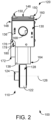
- FIGS. 1 and 2 show of an example position sensor system 100.
- the position sensor system 100 includes a rotor assembly 110 and an explosion-proof encoder 120.
- FIGS. 3 and 4 show the encoder 120. While examples are described herein for use with a rotor assembly 110, the explosion-proof encoder 120 may be used with any device monitorable using one or more sensors.
- the rotor assembly 110 includes a rotor 122 and a shaft 124 extending axially from the rotor 122.
- the rotor assembly 110 is coupled to and driven by a motor (not shown).
- the rotor 122 and shaft 124 are configured to rotate about an axis of rotation 126 (shown in FIG. 2 ) extending through an axial center of the rotor 122 and shaft 124.
- the rotor 122 may be magnetized at one or more locations along its peripheral surface 128 to enable the rotor assembly 110 to be monitored (e.g., by the encoder 120).
- the magnetized surfaces include an incremental or "INC" track configured to provide a predetermined number of pulses proportional to a revolution of the rotor assembly 110 and/or an absolute or "Z" track configured to provide one index pulse per revolution.
- a magnetized location may be at any other surface of the rotor assembly 110 that enables the position sensor system 100 to function as described herein.
- the encoder 120 includes a housing 130 defining a first zone 132 and a second zone 134.
- the housing 130 may include, for example, a plurality of sidewalls including a first set of one or more sidewalls 136 defining the first zone 132 and a second set of one or more sidewalls 138 defining the second zone 134.
- a single sidewall e.g., a cylindrical sidewall
- the housing 130 includes a protection partition 140 having a first surface 142 oriented toward the first zone 132 and a second surface 144 oriented toward the second zone 134.
- the protection partition 140 may extend, for example, laterally across a cavity defined by the housing 130 between opposing sidewalls (e.g., left wall and right wall, front wall and rear wall).
- the first set of sidewalls 136 and/or protection partition 140 are configured to withstand internal ignition and contain the explosion in the first zone 132.
- the encoder 120 includes a cover 146 coupleable to the housing 130 at an upper end portion 148 of the housing 130.
- the cover 146 may extend, for example, across a mouth defined by an upper portion of the first set of sidewalls 136.
- the cover 146 seals and/or shields the first zone 132 from an ambient environment and/or the ambient environment from the first zone 132.
- One or more coupling mechanisms 150 may be used to secure the cover 146 to the first set of sidewalls 136.
- Example coupling mechanisms 150 may include, without limitation, a screw extending through an opening defined in the cover 146 and/or an opening defined in the housing 130, and the like.
- the cover 146 includes a head 152 and a shaft 154 extending from the head 152.
- an upper portion of the shaft 154 defines a groove 156 extending about a perimeter of the shaft 154.
- the groove 156 may be sized, shaped, and/or configured to receive a sealing mechanism 158 that seals or fills a gap between the housing 130 and the cover 146.
- Example sealing mechanisms 158 may include, without limitation, a gasket, an O-ring, and the like.
- a lower portion of the head 152 defines a rabbet 160 extending about a perimeter of the head 152. The rabbet 160 enables the cover 146 to be removably coupled to the housing 130.
- the rabbet 160 may be sized, shaped, and/or configured to receive an object for use in prying the cover 146 from the housing 130. Additionally, the rabbet 160 allows at least a portion of the cover 146 to be deformed without compromising an integrity of a flame path defined between the cover 146 and the housing 130. In this manner, the rabbet 160 may reduce a likelihood of physical damage to the cover 146 and/or housing 130 caused by mechanical impact (e.g., in an attempt to uncouple the cover 146 from the housing 130).
- the encoder 120 includes one or more sensors 162 coupleable to the housing 130 at a lower end portion 164 of the housing 130.
- the sensors 162 may be positioned, for example, in the second zone 134.
- the sensors 162 are coupled to one or more inner surfaces 166 of the second set of sidewalls 138 and/or the second surface 144 of the protection partition 140
- the sensors 162 are configured to detect an object, an activity of an object, and/or a parameter associated with the object.
- the lower end portion 164 may be positioned and/or oriented, for example, toward the rotor assembly 110 (shown in FIGS. 1 and 2 ) such that the sensors 162 are aligned with the peripheral surface 128 of the rotor 122. In this manner, the sensors 162 may detect one or more objects at the peripheral surface 128 (e.g., INC track, Z track) and output one or more signals or pulses corresponding to the detected objects.
- the detected objects enable one or more parameters associated with the rotor assembly 110 to be identified.
- Example parameters may include, for example, a position, angle, movement direction, and/or movement amount.
- the sensors 162 are or include one or more interdigitated magnetoresistive sensor elements that provide single ended two phase or differential outputs.
- the sensors 162 may provide one or more incremental electrical pulse output signals (e.g., "A,” "B,” “A Quad B") indicating an incremental rotation in response to magnetic patterns associated with the INC track and/or one or more index electrical pulse output signals (e.g., "Z") in response to magnetic patterns associated with the Z track.
- the sensors 162 may include a Hall effect sensor, an optical sensor, and/or any other sensor device that enables the position sensor system 100 to function as described herein.
- the encoder 120 includes one or more cable ports 168.
- a cable port 168 may be defined, for example, in one of the first set of sidewalls 136 to provide access to the first zone 132.
- the cable ports 168 may be sized, shaped, and/or configured to receive one or more wirings or cables (not shown) therethrough.
- a cable port 168 provides access to a cavity defined in the housing 130.
- the cable ports 168 enable the position sensor system 100 to communicate with one or more external devices (e.g., control system).
- the parameters associated with the rotor assembly 110 may be communicated with a control system.
- the encoder 120 includes one or more diagnostic indicators 170 that identify a functionality of the position sensor system 100 and present one or more indications corresponding to the identified functionality.
- the diagnostic indicators 170 may include, for example, one or more light emitting diodes (LEDs).
- the diagnostic indicators 170 may be programmed to indicate, for example, one or more wiring errors including a short circuit, misconnection (e.g., leaving an output signal unconnected), application of reverse power, and/or application of power to an output signal connection.
- the encoder 120 includes one or more line driver and/or wiring protection circuits that prevent or reduce a likelihood of damage from short circuits, application of reverse power, and/or application of power to an output signal connection.
- the encoder 120 includes one or more mounting mechanisms 172 (shown in FIGS. 1-3 ) that enable the encoder 120 to be mounted on an external surface (e.g., a surface of another device).
- the mounting mechanisms 172 may provide a plurality of mounting options for application in a diversity of machines.
- the mounting mechanisms 172 may be or include, for example, one or more tabs extending from an outer surface of the encoder 120 and including one or more openings 174 (shown in FIGS. 1 and 3 ) sized, shaped, and/or configured to receive one or more coupling mechanisms (e.g., pins, screws) for coupling the encoder 120 to another device.
- the mounting mechanisms 172 is positionable in a nook 176 defined by a lower surface 178 of one of the first set of sidewalls 136 and a rear surface 180 of one of the second set of sidewalls 138.
- FIGS. 5 and 6 show an example board stack assembly 200 that may be housed in the housing 130.
- the board stack assembly 200 has a plurality of elevations 202 (shown in FIG. 6 ) that enable the board stack assembly 200 to have a smaller footprint.
- the board stack assembly 200 includes two or more printed circuit boards (PCBs) 204 and one or more electronic components coupled to the PCBs 204 that are sized, shaped, and/or oriented to fit in the first zone 132 (shown in FIG. 3 ).
- PCBs printed circuit boards
- the board stack assembly 200 includes an integrated interface device 206 at a first elevation 208 (shown in FIG. 6 ) and a protective wire feedthrough 210 at a second elevation 212 (shown in FIG. 6 ).
- the board stack assembly includes one or more support mechanisms 214 extending between the first elevation 208 and the second elevation 212.
- the interface device 206 may be, for example, a terminal block coupleable to one or more external components.
- the board stack assembly 200 includes one or more embedded anchors or supports 215 opposite the interface device 206 that provide structural support to the interface device 206.
- the supports 215 may be cast, potted, and/or encapsulated, for example.
- the protective wire feedthrough 210 couples one or more elements in the first zone 132 with one or more elements in the second zone 134.
- the protective wire feedthrough 210 has a smooth wall that enables the protective wire feedthrough 210 to be slid through the sensor opening when assembling the encoder 120.
- the protective wire feedthrough 210 may be or include, for example, a line bushing and/or firestop configured to seal a sensor opening defined through the protection partition 140 such that the first zone 132 and second zone 134 are generally shielded from each other.
- the board stack assembly 200 is assembled as a module with the interface device 206 to facilitate assembly of the encoder 120.
- the support mechanisms 214 are configured to provide structural support to the PCBs 204 and/or electronic components (e.g., interface device 206, protective wire feedthrough 210).
- a support mechanism 214 may include a first end portion 216 anchored to the housing 130 (shown in FIGS. 1-4 ), for example, and a second end portion 218 coupled to a PCB cartridge 220.
- a PCB 204 includes one or more mounting openings 222 (shown in FIG. 5 ) that enable one or more coupling mechanisms (e.g., a standoff, a spacer) to extend therethrough for mounting to an inner surface of the housing 130 (e.g., an inner surface of the first set of sidewalls 136).
- the support mechanisms 214 may be enveloped within a casting, potting, or encapsulating compound.
- the board stack assembly 200 also includes a transformer 224, a one-wire communication interface 226, and an energy-limiting apparatus 228 (shown in FIG. 6 ).
- the energy-limiting apparatus 228 may be used or configured to isolate the one-wire communication interface 226 from the transformer 224.
- the energy-limiting apparatus 228 forms a barrier between an intrinsically-safe portion of the board stack assembly 200 and the rest of the board stack assembly 200.
- the energy-limiting apparatus 228 may be, for example, an optical isolator, a galvanic isolator, a Zener barrier, and the like.
- An amount of electrical energy transmitted into or stored in a potentially hazardous environment e.g., electrical energy transmitted to or stored at a sensor 162
- an external power supply is coupled to the board stack assembly 200 (e.g., via the interface device 206), and the energy-limiting apparatus 228 limits an amount of energy transmitted to the protective wire feedthrough 210, which is insulated, isolated, and/or protected.
- the energy-limiting apparatus 228 limits an amount of energy transmitted to the protective wire feedthrough 210, which is insulated, isolated, and/or protected.
- one or more electronic components coupled to the one-wire communication interface 226 may receive a controlled, intrinsically-safe amount of power.
- the one-wire communication interface 226 may extend, for example, through the protective wire feedthrough 210.
- the one-wire communication interface 226 uses a single data line plus ground reference for bidirectional communication.
- the one-wire communication interface 226 enables one or more electronic components (e.g., sensor 162) coupled to the one-wire communication interface 226 to operate over a controlled transformer at a predetermined voltage rate.
- a power source may provide an ultra-wide range of electrical energy, and the energy-limiting apparatus 228 provides a high degree of electrical isolation between the hazardous sections (e.g., at sensor 162 or protective wire feedthrough 210) and non-hazardous sections of circuitry (e.g., at another electrical component coupled to the board stack assembly 200).
- the energy-limiting apparatus 228 reduces a need for a high integrity earth ground.
- An interconnect board (ICB) 229 coupled to the transformer 224 and/or energy-limiting apparatus 228 may be at a third elevation 230 (shown in FIG. 6 ) different from the first elevation 208 and/or second elevation 212.
- the ICB 229 is, includes, or is coupled to a wire management device physically separating a non-protected portion of the board stack assembly 200 from a protected portion of the board stack assembly 200.
- the ICB 229 is coupled to one or more wirings 231 (shown in FIG. 6 ) that are spaced from one or more electronic components that are at an elevation other than that of the ICB 229 (e.g., interface device 206, transformer 224).
- the wirings 231 may be anchored, for example, to facilitate maintaining a position and/or orientation of the wirings 231.
- the board stack assembly 200 may be positioned in the encoder 120 with the interface device 206 at or adjacent to a port (e.g., cable port 168) and the protective wire feedthrough 210 at or adjacent to another port (e.g., a sensor opening defined through the protection partition 140).
- the protective wire feedthrough 210 allows the board stack assembly 200 to be built or assembled within a blind cavity while maintaining intrinsic safety spacing.
- the protective wire feedthrough 210 is coupleable, for example, to one or more sensors 162.
- the protective wire feedthrough 210 extends through a sensor opening defined by the protection partition 140 such that a first portion of the protective wire feedthrough 210 is in the first zone 132 and a second portion of the protective wire feedthrough 210 extends between the first zone 132 and the second zone 134 (shown in FIG. 3 ).
- the sensor opening enables the protective wire feedthrough 210 to be coupled to one or more sensors 162 in the second zone 134.
- the sensors 162 are a sensor stack assembly having a plurality of elevations 232 that enable two or more PCBs 234 and one or more electronic components coupled to the PCBs 234 to fit in the second zone 134 (shown in FIG. 3 ).
- the sensors 162 include a first sensor 236 positioned and/or oriented to detect an INC track or Z track at the peripheral surface 128 of the rotor 122 (shown in FIGS. 1 and 2 ), and a second sensor 238 (shown in FIG. 7 ) positioned and/or oriented to detect the other of the INC track or Z track.
- the sensors 162 may include any type of sensor (e.g., optical, magnetic, Hall effect) that enables the encoder 120 to function as described herein.
- the first sensor 236 and/or second sensor 238 may communicate with one or more electronic components coupled to the board stack assembly PCB 204, for example, via protective wire feedthrough 210.
- the sensor stack assembly includes one or more light pipes 240 (shown in FIG. 4 ) extending between a light emitting diode or LED (e.g., diagnostic indicator 170) at the PCB 234 and one of the second set of sidewalls 138.
- the diagnostic indicators 170 may identify, for example, a functionality of the sensor stack assembly and present one or more indications corresponding to the identified functionality. In this manner, a user may visibly identify a functionality of the board stack assembly 200 and/or sensor stack assembly at an outer surface of the housing 130.
- the diagnostic indicators 170 are power limited (e.g., by the transformer 224 and/or energy-limiting apparatus 228).
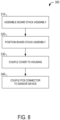
- FIG. 8 shows operations of a method 300 of providing an intrinsically-safe encoder (e.g., encoder 120) that may be used with one or more sensor devices (e.g., sensor 162).
- the method 300 includes assembling a board stack assembly 200 at operation 310.
- the board stack assembly 200 is assembled, for example, to include an interface device 206 and a line bushing (e.g., protective wire feedthrough 210) at a plurality of elevations (e.g., elevations 208 and 212, respectively).
- a line bushing e.g., protective wire feedthrough 2
- the board stack assembly 200 is positioned at operation 320 such that the interface device 206 and a first portion of the protective wire feedthrough 210 are in a first zone 132 defined by a housing 130 of an explosion-proof encoder 120 and a second portion of the protective wire feedthrough 210 extends between the first zone 132 and a second zone 134 defined by the housing 130 of the explosion-proof encoder 120.
- the housing 130 includes a first set of sidewalls 136 defining the first zone 132, a second set of sidewalls 138 defining the second zone 134, and an integrated protection partition 140 delineating the first zone 132 from the second zone 134.
- a cover 146 is coupled to the housing 130 at operation 330 such that the cover 146 seals the first zone 132 from an ambient environment.
- the cover 146 is positioned in a mouth defined by the first set of sidewalls 136 to couple the cover 146 to the housing 130.
- the mouth may be in fluid communication with the first zone 132, for example.
- a coupling mechanism 150 securely couples the cover 146 to the housing 130.
- the protective wire feedthrough 210 is coupled to one or more sensors 162 in the second zone 134 at operation 340.
- the protection partition 140 has a sensor opening defined therethrough between the first zone 132 and the second zone 134 that enables the protective wire feedthrough 210 to be coupled to the sensors 162 in the second zone 134. That is, the protective wire feedthrough 210 may extend through the sensor opening such that a first portion of the protective wire feedthrough 210 is in the first zone 132 and a second portion of the protective wire feedthrough 210 extends through the sensor opening between the first zone 132 and the second zone 134.
- a transformer 224, energy-limiting apparatus 228, and one-wire communication interface 226 in the first zone 132 are used to provide power and power-limited signals outside the housing 130 to one or more sensors 162 in the second zone 134 in an intrinsically-safe manner. That is, the sensors 162 are connected to the transformer 224 and receiver electronics (e.g., encoder 120) by low-impedance, noise-immune connections through an explosion-proof interface.
- receiver electronics e.g., encoder 120
- the transformer 224 and/or energy-limiting apparatus 228 may be used to transmit 40 milliamps (mA) to power an incremental sensor and/or 20 mA to power an index sensor, and receive "A" and "B” signals from the incremental sensor (e.g., via the one-wire communication interface 226) and/or a "Z" signal from the index sensor (e.g., via the one-wire communication interface 226).
- the one-wire communication interface 226 and one or more signals transmitted through the one-wire communication interface 226 are isolated.
- the first set of sidewalls 136 includes a plurality of cable ports 168 defined therethrough.
- the cable ports 168 are in fluid communication with the first zone 132, for example.
- the cable ports 168 include a first opening defined in a first wall of the first set of sidewalls 136 and a second opening defined in a second wall of the first set of sidewalls 136 opposite the first wall.
- the one-wire communication interface 226 and energy-limiting apparatus 228 enable the encoder 120 to communicate with one or more external devices (e.g., control system) via one or more wirings extending through the cable ports 168 in an intrinsically-safe manner.
- one or more diagnostic indicators 170 are configured to identify a functionality of the board stack assembly 200 and present one or more indications corresponding to the identified functionality.
- the diagnostic indicators 170 may include, for example, one or more light emitting diodes (LEDs) coupled to the board stack assembly 200.
- the protective wire feedthrough 210 is electrically connected to the board stack assembly 200 while it is being constructed outside of housing 130. This assembly is inserted into the housing 130.
- the one-wire communication interface 226 extends through the protective wire feedthrough 210 and/or protective barrier (e.g., protection partition 140) until a flange of the protective wire feedthrough 210 comes to rest against the protection partition 140 and is secured with a retaining devise (e.g., a snap ring) on the far side.
- the conductors may be soldered or electrically connected to a sensor PCB stack (e.g., PCB 234) outside of the housing. Then, this sensor stack assembly is secured to the housing 130 in second zone 134.
- the examples described herein include a housing and a protection partition separating a cavity defined by the housing into a first, controlled zone and a second zone exposed to an ambient environment.
- a printed circuit board may be arranged or assembled in a stack to enable the electronic components to be housed in the first zone.
- the board stack assembly includes an integrated energy-limiting apparatus that provides intrinsic safety protection for one or more electronic components coupled to the board stack assembly, including one or more sensors with modular construction, without disrupting the first zone and/or without the need for extraneous wiring.
- Using a protection partition to separate the first zone from the second zone reduces a need for tight seals around a rotor and/or sensor, further rending the examples described herein usable with sensors with modular construction. In this manner, the construction and protection methods and systems described herein are usable in hazardous environments with sensors with modular construction in an efficient, effective, and safe manner.
- the operations illustrated in the drawings may be implemented as software instructions encoded on a computer readable medium, in hardware programmed or designed to perform the operations, or both.
- aspects of the disclosure may be implemented as a system on a chip or other circuitry including a plurality of interconnected, electrically conductive elements.
Landscapes
- Physics & Mathematics (AREA)
- Life Sciences & Earth Sciences (AREA)
- Engineering & Computer Science (AREA)
- Geology (AREA)
- Mining & Mineral Resources (AREA)
- General Physics & Mathematics (AREA)
- Geophysics (AREA)
- Environmental & Geological Engineering (AREA)
- Fluid Mechanics (AREA)
- General Life Sciences & Earth Sciences (AREA)
- Geochemistry & Mineralogy (AREA)
- Transmission And Conversion Of Sensor Element Output (AREA)
Claims (10)
- Ein eigensicherer, explosionsgeschützter Codierer (120), der Folgendes umfasst:ein Gehäuse (130), das eine Vielzahl von Seitenwänden und eine Schutztrennwand (140) beinhaltet, wobei die Vielzahl von Seitenwänden Folgendes beinhaltet: einen ersten Satz von einer oder mehreren Seitenwänden (136), die eine erste Zone (132) definieren, und einen zweiten Satz von einer oder mehreren Seitenwänden (138), die eine zweite Zone (134) definieren, die einer Umgebung ausgesetzt ist, wobei die Schutztrennwand Folgendes aufweist: eine erste Oberfläche (142), die auf die erste Zone ausgerichtet ist, und eine zweite Oberfläche (144), die auf die zweite Zone ausgerichtet ist, wobei die Schutztrennwand eine Sensoröffnung aufweist, die durch sie hindurch zwischen der ersten Zone und der zweiten Zone definiert ist;eine Leiterplatten-Stapel-Anordnung (200), die Folgendes beinhaltet: zwei oder mehr Leiterplatten (204), die durch eine Ebene bzw. Höhenlage (elevation) einer Vielzahl von Höhenlagen getrennt sind, eine Schnittstellenvorrichtung (206), eine Energiebegrenzungsvorrichtung (228), eine Schutzleiter-Durchführung (210), die mit den zwei oder mehr Leiterplatten in der ersten Zone gekoppelt ist, und einem Trägermechanismus (214), der mit den zwei oder mehreren Leiterplatten in der ersten Zone gekoppelt ist, wobei sich die Schutzleiter-Durchführung durch die Sensoröffnung zwischen der ersten Zone und der zweiten Zone erstreckt, wobei sich der Trägermechanismus zwischen einer ersten Höhenlage der Vielzahl von Höhenlagen und einer zweiten Höhenlage der Vielzahl von Höhenlagen erstreckt;eine Sensorvorrichtung (162), die mit der Schutzleiter-Durchführung in der zweiten Zone gekoppelt ist; undeine Abdeckung (146), die so konfiguriert ist, dass sie mit dem ersten Satz von einer oder mehreren Seitenwänden in Eingriff kommt, sodass die Abdeckung die erste Zone gegenüber der Umgebung abdichtet.
- Der eigensichere, explosionsgeschützte Codierer nach Anspruch 1, wobei die Leiterplatten-Stapel-Anordnung einen Transformator (224) und eine Ein-Draht-Kommunikationsschnittstelle (226) beinhaltet, die mit den zwei oder mehr Leiterplatten in der ersten Zone gekoppelt ist, wobei die energiebegrenzende Vorrichtung so konfiguriert ist, dass sie die Ein-Draht-Kommunikationsschnittstelle galvanisch vom Transformator isoliert.
- Der eigensichere, explosionsgeschützte Codierer nach irgendeinem der vorstehenden Ansprüche, der ferner eine Diagnoseanzeige (170) umfasst, die mit der Schutzleiter-Durchführung in der zweiten Zone gekoppelt ist, wobei die Diagnoseanzeige so konfiguriert ist, dass sie eine Funktionalität der Leiterplatten-Stapel-Anordnung identifiziert und entsprechend der identifizierten Funktionalität eine oder mehrere Angaben präsentiert.
- Der eigensichere, explosionsgeschützte Codierer nach irgendeinem der vorstehenden Ansprüche, wobei die Abdeckung einen Kopf (152) und einen sich von dem Kopf erstreckenden Schaft (154) beinhaltet, wobei ein unterer Abschnitt des Kopfes einen Falz (160) definiert, der sich um einen Umfang des Kopfes erstreckt.
- Der eigensichere, explosionsgeschützte Codierer nach Anspruch 4, wobei der erste Satz von einer oder mehreren Seitenwänden eine Mündung in Fluidverbindung mit der ersten Zone definiert, wobei der Schaft der Abdeckung in der Mündung positionierbar ist, um die Abdeckung mit dem ersten Satz von einer oder mehreren Seitenwänden zu koppeln.
- Der eigensichere, explosionsgeschützte Codierer nach irgendeinem der Ansprüche 4 oder 5, der ferner einen Dichtungsmechanismus (158) umfasst, wobei ein oberer Abschnitt des Schaftes der Abdeckung eine Nut (156) definiert, die zur Aufnahme des Dichtungsmechanismus konfiguriert ist.
- Der eigensichere, explosionsgeschützte Codierer nach irgendeinem der vorstehenden Ansprüche, der ferner einen Kupplungsmechanismus (150) umfasst, der die Abdeckung mit dem ersten Satz von einer oder mehreren Seitenwänden verbindet.
- Der eigensichere, explosionsgeschützte Codierer nach irgendeinem der vorstehenden Ansprüche, wobei der erste Satz von einer oder mehreren Seitenwänden eine Vielzahl von durch sie hindurch definierten Öffnungen (168) beinhaltet, wobei die Vielzahl von Öffnungen in Fluidverbindung mit der ersten Zone steht, wobei die Vielzahl von Öffnungen Folgendes beinhaltet: eine erste Öffnung, die in einer ersten Wand des ersten Satzes von einer oder mehreren Seitenwänden definiert ist, und eine zweite Öffnung, die in einer zweiten Wand des ersten Satzes von einer oder mehreren Seitenwänden gegenüber der ersten Wand definiert ist.
- Der eigensichere, explosionsgeschützte Codierer nach irgendeinem der vorstehenden Ansprüche, der ferner einen Montagemechanismus (172) umfasst, der mit einer Außenfläche koppelbar ist.
- Der eigensichere, explosionsgeschützte Codierer nach irgendeinem der vorstehenden Ansprüche, wobei die Leiterplatten-Stapel-Anordnung Folgendes beinhaltet: die Schnittstellenvorrichtung in der ersten Zone auf der ersten Höhenlage der Vielzahl von Höhenlagen und die Schutzleiter-Durchführung auf der zweiten Höhenlage der Vielzahl von Höhenlagen, wobei die Schutzleiter-Durchführung Folgendes umfasst: einen ersten Abschnitt in der ersten Zone und einen zweiten Abschnitt, der sich zwischen der ersten Zone und der zweiten Zone erstreckt.
Applications Claiming Priority (2)
| Application Number | Priority Date | Filing Date | Title |
|---|---|---|---|
| US15/691,429 US10641624B2 (en) | 2017-08-30 | 2017-08-30 | Intrinsically-safe, explosion-proof encoder |
| PCT/US2018/048741 WO2019046526A1 (en) | 2017-08-30 | 2018-08-30 | INTRINSIC SECURITY ANTI-DEFLAGRANT ENCODER |
Publications (4)
| Publication Number | Publication Date |
|---|---|
| EP3676916A1 EP3676916A1 (de) | 2020-07-08 |
| EP3676916A4 EP3676916A4 (de) | 2021-04-28 |
| EP3676916B1 true EP3676916B1 (de) | 2023-10-04 |
| EP3676916C0 EP3676916C0 (de) | 2023-10-04 |
Family
ID=65437425
Family Applications (1)
| Application Number | Title | Priority Date | Filing Date |
|---|---|---|---|
| EP18852333.6A Active EP3676916B1 (de) | 2017-08-30 | 2018-08-30 | Eigensicherer explosionsgeschützter codierer |
Country Status (5)
| Country | Link |
|---|---|
| US (1) | US10641624B2 (de) |
| EP (1) | EP3676916B1 (de) |
| CN (1) | CN111386633B (de) |
| CA (1) | CA3073046A1 (de) |
| WO (1) | WO2019046526A1 (de) |
Families Citing this family (6)
| Publication number | Priority date | Publication date | Assignee | Title |
|---|---|---|---|---|
| US10670054B2 (en) * | 2017-10-25 | 2020-06-02 | Dresser, Llc | Constructing valve positioners for hazardous areas |
| US11063382B2 (en) * | 2018-05-22 | 2021-07-13 | Flowserve Management Company | Waterproof and explosion-proof circuit board and electronic valve actuator for flow control applications |
| DE102019118778A1 (de) * | 2019-07-11 | 2021-01-14 | Endress + Hauser Flowtec Ag | Gehäusemodul und Feldgerät |
| WO2022093480A2 (en) * | 2020-10-01 | 2022-05-05 | Joy Global Underground Mining Llc | Bolter |
| US12276529B2 (en) | 2021-06-11 | 2025-04-15 | Abb Schweiz Ag | Explosion management display and methods thereof |
| US11549832B2 (en) * | 2021-06-11 | 2023-01-10 | Abb Schweiz Ag | Explosion management and methods thereof |
Family Cites Families (14)
| Publication number | Priority date | Publication date | Assignee | Title |
|---|---|---|---|---|
| US5954526A (en) * | 1996-10-04 | 1999-09-21 | Rosemount Inc. | Process control transmitter with electrical feedthrough assembly |
| WO1998057186A2 (en) * | 1997-06-09 | 1998-12-17 | Magnetrol International, Inc. | Dual compartment instrument housing |
| US6109979A (en) * | 1997-10-31 | 2000-08-29 | Micro Motion, Inc. | Explosion proof feedthrough connector |
| US6300897B1 (en) * | 1999-07-02 | 2001-10-09 | Rosemount Inc. | Stabilization in a radar level gauge |
| US6484107B1 (en) | 1999-09-28 | 2002-11-19 | Rosemount Inc. | Selectable on-off logic modes for a sensor module |
| US6331674B1 (en) * | 2000-03-31 | 2001-12-18 | Micro Motion, Inc. | Explosion proof terminal block housing that may be opened |
| JP4191940B2 (ja) * | 2002-03-12 | 2008-12-03 | アルプス電気株式会社 | ロータリポジションセンサ |
| US8929948B2 (en) * | 2008-06-17 | 2015-01-06 | Rosemount Inc. | Wireless communication adapter for field devices |
| US8535014B2 (en) * | 2008-06-23 | 2013-09-17 | Zoeller Pump Company, Llc | System and method for explosion-proof pump |
| US8829740B2 (en) | 2010-05-27 | 2014-09-09 | Rockwell Automation Technologies, Inc. | Sealed linear motor system |
| KR200476989Y1 (ko) | 2010-08-16 | 2015-04-23 | 현대중공업 주식회사 | 복합 방폭형 전동기 |
| DE102012005637B4 (de) | 2012-03-22 | 2019-02-21 | Krohne Messtechnik Gmbh | Messgerät |
| US9379746B2 (en) * | 2014-06-30 | 2016-06-28 | Texas Instruments Incorporated | Isolation circuits for digital communications and methods to provide isolation for digital communications |
| DE102014016052A1 (de) * | 2014-10-30 | 2016-05-04 | Hengstler Gmbh | Explosionsgeschütztes Gehäuse für einen Sensor |
-
2017
- 2017-08-30 US US15/691,429 patent/US10641624B2/en active Active
-
2018
- 2018-08-30 CA CA3073046A patent/CA3073046A1/en active Pending
- 2018-08-30 WO PCT/US2018/048741 patent/WO2019046526A1/en not_active Ceased
- 2018-08-30 CN CN201880056931.XA patent/CN111386633B/zh active Active
- 2018-08-30 EP EP18852333.6A patent/EP3676916B1/de active Active
Also Published As
| Publication number | Publication date |
|---|---|
| CN111386633B (zh) | 2021-10-22 |
| EP3676916A1 (de) | 2020-07-08 |
| RU2020112163A3 (de) | 2022-03-11 |
| US10641624B2 (en) | 2020-05-05 |
| CA3073046A1 (en) | 2019-03-07 |
| EP3676916C0 (de) | 2023-10-04 |
| EP3676916A4 (de) | 2021-04-28 |
| US20190063964A1 (en) | 2019-02-28 |
| RU2020112163A (ru) | 2021-09-30 |
| CN111386633A (zh) | 2020-07-07 |
| WO2019046526A1 (en) | 2019-03-07 |
Similar Documents
| Publication | Publication Date | Title |
|---|---|---|
| EP3676916B1 (de) | Eigensicherer explosionsgeschützter codierer | |
| US7875797B2 (en) | Housing with display—and/or operating-element | |
| CN110546346B (zh) | 带有集成的选择性电子开关电路的压力舱壁结构、包含此类选择性电子开关电路的压力隔离外壳及其制造方法 | |
| US9541428B2 (en) | Interface between a sensor unit and an explosion resistant housing | |
| EP3123118B1 (de) | Prozessvariablensender mit abnehmbarer anschlussleiste | |
| US9520599B2 (en) | Modular intrinsically-safe field device power module | |
| US9784092B2 (en) | Downhole control device | |
| US12366157B2 (en) | Wellbore logging device | |
| US11605918B2 (en) | Protection device for a plug-in connection | |
| US20220333959A1 (en) | Angular displacement measuring arrangement, angular displacement measuring system and electric motor | |
| CN220288866U (zh) | 用于工业过程的过程变量变送器 | |
| RU2776257C2 (ru) | Внутренне безопасный взрывоустойчивый кодер | |
| US11448063B2 (en) | Downhole measurement tool assembly for measuring and storing at least one quantity in a wellbore and for wireless surface read-out | |
| ES2895444T3 (es) | Dispositivo para la transmisión de señales | |
| CN211856931U (zh) | 一种随钻核磁共振测井仪 | |
| WO2005017314A1 (en) | Side entry leak protection for sondes | |
| WO2004082075A2 (en) | Electrical cordset with integral signal conditioning circuitry | |
| KR102629423B1 (ko) | 사물 인터넷 센서 및 이를 이용한 산업용 장비의 데이터 획득방법 | |
| CN219321606U (zh) | 旋转设备监控装置 | |
| WO2025244877A1 (en) | Modular input/output node | |
| CN105519231A (zh) | 振动传感器和电子装置 | |
| CN102497758A (zh) | 矿用本安型隔离耦合器 | |
| AU2019284047A1 (en) | Electronic devices |
Legal Events
| Date | Code | Title | Description |
|---|---|---|---|
| STAA | Information on the status of an ep patent application or granted ep patent |
Free format text: STATUS: THE INTERNATIONAL PUBLICATION HAS BEEN MADE |
|
| PUAI | Public reference made under article 153(3) epc to a published international application that has entered the european phase |
Free format text: ORIGINAL CODE: 0009012 |
|
| STAA | Information on the status of an ep patent application or granted ep patent |
Free format text: STATUS: REQUEST FOR EXAMINATION WAS MADE |
|
| 17P | Request for examination filed |
Effective date: 20200319 |
|
| AK | Designated contracting states |
Kind code of ref document: A1 Designated state(s): AL AT BE BG CH CY CZ DE DK EE ES FI FR GB GR HR HU IE IS IT LI LT LU LV MC MK MT NL NO PL PT RO RS SE SI SK SM TR |
|
| AX | Request for extension of the european patent |
Extension state: BA ME |
|
| DAV | Request for validation of the european patent (deleted) | ||
| DAX | Request for extension of the european patent (deleted) | ||
| A4 | Supplementary search report drawn up and despatched |
Effective date: 20210331 |
|
| RIC1 | Information provided on ipc code assigned before grant |
Ipc: H01R 13/533 20060101AFI20210325BHEP Ipc: H01R 13/52 20060101ALI20210325BHEP Ipc: G01D 11/24 20060101ALI20210325BHEP |
|
| STAA | Information on the status of an ep patent application or granted ep patent |
Free format text: STATUS: EXAMINATION IS IN PROGRESS |
|
| 17Q | First examination report despatched |
Effective date: 20220825 |
|
| GRAP | Despatch of communication of intention to grant a patent |
Free format text: ORIGINAL CODE: EPIDOSNIGR1 |
|
| STAA | Information on the status of an ep patent application or granted ep patent |
Free format text: STATUS: GRANT OF PATENT IS INTENDED |
|
| INTG | Intention to grant announced |
Effective date: 20230414 |
|
| GRAS | Grant fee paid |
Free format text: ORIGINAL CODE: EPIDOSNIGR3 |
|
| GRAA | (expected) grant |
Free format text: ORIGINAL CODE: 0009210 |
|
| STAA | Information on the status of an ep patent application or granted ep patent |
Free format text: STATUS: THE PATENT HAS BEEN GRANTED |
|
| AK | Designated contracting states |
Kind code of ref document: B1 Designated state(s): AL AT BE BG CH CY CZ DE DK EE ES FI FR GB GR HR HU IE IS IT LI LT LU LV MC MK MT NL NO PL PT RO RS SE SI SK SM TR |
|
| REG | Reference to a national code |
Ref country code: GB Ref legal event code: FG4D |
|
| REG | Reference to a national code |
Ref country code: CH Ref legal event code: EP |
|
| REG | Reference to a national code |
Ref country code: IE Ref legal event code: FG4D |
|
| REG | Reference to a national code |
Ref country code: DE Ref legal event code: R096 Ref document number: 602018058864 Country of ref document: DE |
|
| U01 | Request for unitary effect filed |
Effective date: 20231102 |
|
| U07 | Unitary effect registered |
Designated state(s): AT BE BG DE DK EE FI FR IT LT LU LV MT NL PT SE SI Effective date: 20231107 |
|
| PG25 | Lapsed in a contracting state [announced via postgrant information from national office to epo] |
Ref country code: GR Free format text: LAPSE BECAUSE OF FAILURE TO SUBMIT A TRANSLATION OF THE DESCRIPTION OR TO PAY THE FEE WITHIN THE PRESCRIBED TIME-LIMIT Effective date: 20240105 |
|
| PG25 | Lapsed in a contracting state [announced via postgrant information from national office to epo] |
Ref country code: IS Free format text: LAPSE BECAUSE OF FAILURE TO SUBMIT A TRANSLATION OF THE DESCRIPTION OR TO PAY THE FEE WITHIN THE PRESCRIBED TIME-LIMIT Effective date: 20240204 |
|
| PG25 | Lapsed in a contracting state [announced via postgrant information from national office to epo] |
Ref country code: ES Free format text: LAPSE BECAUSE OF FAILURE TO SUBMIT A TRANSLATION OF THE DESCRIPTION OR TO PAY THE FEE WITHIN THE PRESCRIBED TIME-LIMIT Effective date: 20231004 |
|
| PG25 | Lapsed in a contracting state [announced via postgrant information from national office to epo] |
Ref country code: IS Free format text: LAPSE BECAUSE OF FAILURE TO SUBMIT A TRANSLATION OF THE DESCRIPTION OR TO PAY THE FEE WITHIN THE PRESCRIBED TIME-LIMIT Effective date: 20240204 Ref country code: GR Free format text: LAPSE BECAUSE OF FAILURE TO SUBMIT A TRANSLATION OF THE DESCRIPTION OR TO PAY THE FEE WITHIN THE PRESCRIBED TIME-LIMIT Effective date: 20240105 Ref country code: ES Free format text: LAPSE BECAUSE OF FAILURE TO SUBMIT A TRANSLATION OF THE DESCRIPTION OR TO PAY THE FEE WITHIN THE PRESCRIBED TIME-LIMIT Effective date: 20231004 |
|
| PG25 | Lapsed in a contracting state [announced via postgrant information from national office to epo] |
Ref country code: RS Free format text: LAPSE BECAUSE OF FAILURE TO SUBMIT A TRANSLATION OF THE DESCRIPTION OR TO PAY THE FEE WITHIN THE PRESCRIBED TIME-LIMIT Effective date: 20231004 Ref country code: PL Free format text: LAPSE BECAUSE OF FAILURE TO SUBMIT A TRANSLATION OF THE DESCRIPTION OR TO PAY THE FEE WITHIN THE PRESCRIBED TIME-LIMIT Effective date: 20231004 Ref country code: NO Free format text: LAPSE BECAUSE OF FAILURE TO SUBMIT A TRANSLATION OF THE DESCRIPTION OR TO PAY THE FEE WITHIN THE PRESCRIBED TIME-LIMIT Effective date: 20240104 Ref country code: HR Free format text: LAPSE BECAUSE OF FAILURE TO SUBMIT A TRANSLATION OF THE DESCRIPTION OR TO PAY THE FEE WITHIN THE PRESCRIBED TIME-LIMIT Effective date: 20231004 |
|
| REG | Reference to a national code |
Ref country code: DE Ref legal event code: R097 Ref document number: 602018058864 Country of ref document: DE |
|
| PG25 | Lapsed in a contracting state [announced via postgrant information from national office to epo] |
Ref country code: CZ Free format text: LAPSE BECAUSE OF FAILURE TO SUBMIT A TRANSLATION OF THE DESCRIPTION OR TO PAY THE FEE WITHIN THE PRESCRIBED TIME-LIMIT Effective date: 20231004 |
|
| PG25 | Lapsed in a contracting state [announced via postgrant information from national office to epo] |
Ref country code: SK Free format text: LAPSE BECAUSE OF FAILURE TO SUBMIT A TRANSLATION OF THE DESCRIPTION OR TO PAY THE FEE WITHIN THE PRESCRIBED TIME-LIMIT Effective date: 20231004 |
|
| PG25 | Lapsed in a contracting state [announced via postgrant information from national office to epo] |
Ref country code: SM Free format text: LAPSE BECAUSE OF FAILURE TO SUBMIT A TRANSLATION OF THE DESCRIPTION OR TO PAY THE FEE WITHIN THE PRESCRIBED TIME-LIMIT Effective date: 20231004 Ref country code: SK Free format text: LAPSE BECAUSE OF FAILURE TO SUBMIT A TRANSLATION OF THE DESCRIPTION OR TO PAY THE FEE WITHIN THE PRESCRIBED TIME-LIMIT Effective date: 20231004 Ref country code: RO Free format text: LAPSE BECAUSE OF FAILURE TO SUBMIT A TRANSLATION OF THE DESCRIPTION OR TO PAY THE FEE WITHIN THE PRESCRIBED TIME-LIMIT Effective date: 20231004 Ref country code: CZ Free format text: LAPSE BECAUSE OF FAILURE TO SUBMIT A TRANSLATION OF THE DESCRIPTION OR TO PAY THE FEE WITHIN THE PRESCRIBED TIME-LIMIT Effective date: 20231004 |
|
| PLBE | No opposition filed within time limit |
Free format text: ORIGINAL CODE: 0009261 |
|
| STAA | Information on the status of an ep patent application or granted ep patent |
Free format text: STATUS: NO OPPOSITION FILED WITHIN TIME LIMIT |
|
| 26N | No opposition filed |
Effective date: 20240705 |
|
| U21 | Renewal fee for the european patent with unitary effect paid with additional fee |
Year of fee payment: 7 Effective date: 20241127 |
|
| REG | Reference to a national code |
Ref country code: CH Ref legal event code: PL |
|
| GBPC | Gb: european patent ceased through non-payment of renewal fee |
Effective date: 20240830 |
|
| PG25 | Lapsed in a contracting state [announced via postgrant information from national office to epo] |
Ref country code: MC Free format text: LAPSE BECAUSE OF FAILURE TO SUBMIT A TRANSLATION OF THE DESCRIPTION OR TO PAY THE FEE WITHIN THE PRESCRIBED TIME-LIMIT Effective date: 20231004 Ref country code: CH Free format text: LAPSE BECAUSE OF NON-PAYMENT OF DUE FEES Effective date: 20240831 |
|
| PG25 | Lapsed in a contracting state [announced via postgrant information from national office to epo] |
Ref country code: GB Free format text: LAPSE BECAUSE OF NON-PAYMENT OF DUE FEES Effective date: 20240830 |
|
| PG25 | Lapsed in a contracting state [announced via postgrant information from national office to epo] |
Ref country code: IE Free format text: LAPSE BECAUSE OF NON-PAYMENT OF DUE FEES Effective date: 20240830 |
|
| U20 | Renewal fee for the european patent with unitary effect paid |
Year of fee payment: 8 Effective date: 20250827 |
|
| PG25 | Lapsed in a contracting state [announced via postgrant information from national office to epo] |
Ref country code: CY Free format text: LAPSE BECAUSE OF FAILURE TO SUBMIT A TRANSLATION OF THE DESCRIPTION OR TO PAY THE FEE WITHIN THE PRESCRIBED TIME-LIMIT; INVALID AB INITIO Effective date: 20180830 |
|
| PG25 | Lapsed in a contracting state [announced via postgrant information from national office to epo] |
Ref country code: HU Free format text: LAPSE BECAUSE OF FAILURE TO SUBMIT A TRANSLATION OF THE DESCRIPTION OR TO PAY THE FEE WITHIN THE PRESCRIBED TIME-LIMIT; INVALID AB INITIO Effective date: 20180830 |