EP3676936B1 - Elektronische vorrichtung und verfahren zur steuerung davon - Google Patents
Elektronische vorrichtung und verfahren zur steuerung davon Download PDFInfo
- Publication number
- EP3676936B1 EP3676936B1 EP19754571.8A EP19754571A EP3676936B1 EP 3676936 B1 EP3676936 B1 EP 3676936B1 EP 19754571 A EP19754571 A EP 19754571A EP 3676936 B1 EP3676936 B1 EP 3676936B1
- Authority
- EP
- European Patent Office
- Prior art keywords
- external apparatus
- signal
- battery
- external
- charging
- Prior art date
- Legal status (The legal status is an assumption and is not a legal conclusion. Google has not performed a legal analysis and makes no representation as to the accuracy of the status listed.)
- Active
Links
Images


Classifications
-
- H—ELECTRICITY
- H02—GENERATION; CONVERSION OR DISTRIBUTION OF ELECTRIC POWER
- H02J—ELECTRIC POWER NETWORKS; CIRCUIT ARRANGEMENTS OR SYSTEMS FOR SUPPLYING OR DISTRIBUTING ELECTRIC POWER; SYSTEMS FOR STORING ELECTRIC ENERGY
- H02J7/00—Circuit arrangements for charging or discharging batteries or for supplying loads from batteries
- H02J7/40—Circuit arrangements for charging or discharging batteries or for supplying loads from batteries characterised by the exchange of charge or discharge related data
- H02J7/42—Circuit arrangements for charging or discharging batteries or for supplying loads from batteries characterised by the exchange of charge or discharge related data with electronic devices having internal batteries, e.g. mobile phones
-
- H—ELECTRICITY
- H02—GENERATION; CONVERSION OR DISTRIBUTION OF ELECTRIC POWER
- H02J—ELECTRIC POWER NETWORKS; CIRCUIT ARRANGEMENTS OR SYSTEMS FOR SUPPLYING OR DISTRIBUTING ELECTRIC POWER; SYSTEMS FOR STORING ELECTRIC ENERGY
- H02J50/00—Circuit arrangements or systems for wireless supply or distribution of electric power
- H02J50/005—Mechanical details of housing or structure aiming to accommodate the power transfer means, e.g. mechanical integration of coils, antennas or transducers into emitting or receiving devices
-
- H—ELECTRICITY
- H02—GENERATION; CONVERSION OR DISTRIBUTION OF ELECTRIC POWER
- H02J—ELECTRIC POWER NETWORKS; CIRCUIT ARRANGEMENTS OR SYSTEMS FOR SUPPLYING OR DISTRIBUTING ELECTRIC POWER; SYSTEMS FOR STORING ELECTRIC ENERGY
- H02J50/00—Circuit arrangements or systems for wireless supply or distribution of electric power
- H02J50/20—Circuit arrangements or systems for wireless supply or distribution of electric power using microwaves or radio frequency waves
- H02J50/23—Circuit arrangements or systems for wireless supply or distribution of electric power using microwaves or radio frequency waves characterised by the type of transmitting antennas, e.g. directional array antennas or Yagi antennas
-
- H—ELECTRICITY
- H02—GENERATION; CONVERSION OR DISTRIBUTION OF ELECTRIC POWER
- H02J—ELECTRIC POWER NETWORKS; CIRCUIT ARRANGEMENTS OR SYSTEMS FOR SUPPLYING OR DISTRIBUTING ELECTRIC POWER; SYSTEMS FOR STORING ELECTRIC ENERGY
- H02J50/00—Circuit arrangements or systems for wireless supply or distribution of electric power
- H02J50/20—Circuit arrangements or systems for wireless supply or distribution of electric power using microwaves or radio frequency waves
- H02J50/27—Circuit arrangements or systems for wireless supply or distribution of electric power using microwaves or radio frequency waves characterised by the type of receiving antennas, e.g. rectennas
-
- H—ELECTRICITY
- H02—GENERATION; CONVERSION OR DISTRIBUTION OF ELECTRIC POWER
- H02J—ELECTRIC POWER NETWORKS; CIRCUIT ARRANGEMENTS OR SYSTEMS FOR SUPPLYING OR DISTRIBUTING ELECTRIC POWER; SYSTEMS FOR STORING ELECTRIC ENERGY
- H02J50/00—Circuit arrangements or systems for wireless supply or distribution of electric power
- H02J50/40—Circuit arrangements or systems for wireless supply or distribution of electric power using two or more transmitting or receiving devices
-
- H—ELECTRICITY
- H02—GENERATION; CONVERSION OR DISTRIBUTION OF ELECTRIC POWER
- H02J—ELECTRIC POWER NETWORKS; CIRCUIT ARRANGEMENTS OR SYSTEMS FOR SUPPLYING OR DISTRIBUTING ELECTRIC POWER; SYSTEMS FOR STORING ELECTRIC ENERGY
- H02J50/00—Circuit arrangements or systems for wireless supply or distribution of electric power
- H02J50/60—Circuit arrangements or systems for wireless supply or distribution of electric power responsive to the presence of foreign objects, e.g. detection of living beings
-
- H—ELECTRICITY
- H02—GENERATION; CONVERSION OR DISTRIBUTION OF ELECTRIC POWER
- H02J—ELECTRIC POWER NETWORKS; CIRCUIT ARRANGEMENTS OR SYSTEMS FOR SUPPLYING OR DISTRIBUTING ELECTRIC POWER; SYSTEMS FOR STORING ELECTRIC ENERGY
- H02J50/00—Circuit arrangements or systems for wireless supply or distribution of electric power
- H02J50/80—Circuit arrangements or systems for wireless supply or distribution of electric power involving the exchange of data, concerning supply or distribution of electric power, between transmitting devices and receiving devices
-
- H—ELECTRICITY
- H02—GENERATION; CONVERSION OR DISTRIBUTION OF ELECTRIC POWER
- H02J—ELECTRIC POWER NETWORKS; CIRCUIT ARRANGEMENTS OR SYSTEMS FOR SUPPLYING OR DISTRIBUTING ELECTRIC POWER; SYSTEMS FOR STORING ELECTRIC ENERGY
- H02J50/00—Circuit arrangements or systems for wireless supply or distribution of electric power
- H02J50/90—Circuit arrangements or systems for wireless supply or distribution of electric power involving detection or optimisation of position, e.g. alignment
-
- H—ELECTRICITY
- H02—GENERATION; CONVERSION OR DISTRIBUTION OF ELECTRIC POWER
- H02J—ELECTRIC POWER NETWORKS; CIRCUIT ARRANGEMENTS OR SYSTEMS FOR SUPPLYING OR DISTRIBUTING ELECTRIC POWER; SYSTEMS FOR STORING ELECTRIC ENERGY
- H02J7/00—Circuit arrangements for charging or discharging batteries or for supplying loads from batteries
- H02J7/02—Circuit arrangements for charging or discharging batteries or for supplying loads from batteries for charging batteries from AC mains by converters
-
- H—ELECTRICITY
- H02—GENERATION; CONVERSION OR DISTRIBUTION OF ELECTRIC POWER
- H02J—ELECTRIC POWER NETWORKS; CIRCUIT ARRANGEMENTS OR SYSTEMS FOR SUPPLYING OR DISTRIBUTING ELECTRIC POWER; SYSTEMS FOR STORING ELECTRIC ENERGY
- H02J7/00—Circuit arrangements for charging or discharging batteries or for supplying loads from batteries
- H02J7/80—Circuit arrangements for charging or discharging batteries or for supplying loads from batteries including monitoring or indicating arrangements
- H02J7/82—Control of state of charge [SOC]
Definitions
- the disclosure relates to an electronic apparatus and a controlling method thereof. More particularly, the disclosure relates to an electronic apparatus capable of charging battery of an external apparatus and a method for controlling thereof.
- the aforementioned method has an issue in that an electronic apparatus, such as a smartphone must be located to be close to a wireless charging apparatus. For example, since the charging is performed only at a close distance, there is an issue that space is limited in the same manner as charging using a cable.
- battery of only one electronic apparatus can be charged using one wireless charging apparatus, and each battery of a plurality of electronic apparatuses cannot be simultaneously charged through one wireless charging apparatus.
- EP 3 190 686 A1 discloses a device and method relate to the reseption of a charging request from an external apparatus, the determination of a distance and a direction in which the external apparatus is positioned, the transmission of an ultrasonic signal to the external apparatus based on the direction and distance at which the external apparatus is positioned.
- US 2017/0331332 A1 discloses a wireless power transmission device and a control method thereof.
- the wireless power transmission device includes an array antenna including multiple cells that radiate wireless power; and combines cells of the multiple cells included in the array antenna based on information of the position of an external electronic device and controls the cells included in the antenna to radiate the wireless power towards the external electronic device.
- US 2017/0358950 A1 discloses a wireless transmitter estimating a client location in space and transmitting power in the form of electromagnetic waves to that location.
- an aspect of the disclosure is to provide an electronic apparatus capable of charging batteries of a plurality of electronic apparatuses through a wireless charging apparatus and a method for controlling thereof.
- an electronic apparatus includes a directional antenna, and a processor configured to, based on a signal to request charging of a battery of an external apparatus being received from the external apparatus through the directional antenna, identify a location of the external apparatus based on intensity of the signal and a direction in which the signal is received, and control the directional antenna to transmit a radio frequency (RF) signal to charge battery of the external apparatus toward the external apparatus.
- RF radio frequency
- the processor may, based on signals to request charging of batteries of a first external apparatus and a second external apparatus being received from the first external apparatus and the second external apparatus respectively, transmit an RF signal to charge a battery of the first external apparatus to the first external apparatus and an RF signal to charge a battery of the second external apparatus to the second external apparatus sequentially according to a priority.
- the processor may, based on signals to request charging of batteries of the first external apparatus and the second external apparatus being received from the first external apparatus and the second external apparatus respectively, identify intensities of RF signal to be transmitted to each of the first external apparatus and the second external apparatus according to a priority, and transmit an RF signal to charge a battery of the first external apparatus and a battery of the second external apparatus respectively based on the intensities of the RF signal to the first external apparatus and the second external apparatus.
- the processor may, based on the external apparatus being identified to be positioned at a location that is farther than a preset distance from the electronic apparatus based on a location of the external apparatus, provide guide information to request to move the external apparatus to be a location that is closer than the preset distance.
- the electronic apparatus may further include a sensor, wherein the processor may, based on an electric field corresponding to a human body being detected by the sensor in a direction where the external apparatus is located, adjust intensity of the RF signal that is transmitted to the external apparatus to be less than or equal to a preset threshold value.
- the processor may transmit, to a user terminal apparatus, information on charging intensity of the external apparatus corresponding to the intensity of the RF signal and information on remaining capacity of the battery received from the external apparatus.
- the processor may, based on information to inform that charging of the battery is completed being received from the external apparatus, stop transmitting the RF signal.
- the processor may, based on a signal to request charging of the battery being received from the external apparatus, transmit, to the external apparatus, an authentication request signal to confirm whether the external apparatus is an authenticated apparatus based on a location of the external apparatus, and based on authentication information being received from the external apparatus, to respond to transmission of the authentication request signal, identify whether the external apparatus is an authenticated apparatus based on the authentication information and when the external apparatus is an authenticated apparatus, transmit the RF signal to the external apparatus.
- a method for controlling an electronic apparatus includes, based on a signal to request charging of a battery of an external apparatus being received from the external apparatus, identifying a location of the external apparatus based on intensity of the signal and a direction in which the signal is received, and transmitting a RF signal to charge battery of the external apparatus toward the external apparatus based on the location of the external apparatus.
- the transmitting an RF signal may include, based on signals to request charging of batteries of a first external apparatus and a second external apparatus being received from the first external apparatus and the second external apparatus respectively, transmitting an RF signal to charge a battery of the first external apparatus to the first external apparatus and a battery of the second external apparatus to the second external apparatus sequentially according to a priority.
- the transmitting an RF signal may include, based on signals to request charging of batteries of the first external apparatus and the second external apparatus being received from the first external apparatus and the second external apparatus respectively, identifying intensities of RF signal to be transmitted to each of the first external apparatus and the second external apparatus according to a priority, and transmitting an RF signal to charge a battery of the first external apparatus and a battery of the second external apparatus respectively based on the intensities of the RF signal to the first external apparatus and the second external apparatus.
- the method may further include, based on the external apparatus being identified to be positioned at a location that is farther than a preset distance from the electronic apparatus based on a location of the external apparatus, providing guide information to request to move the external apparatus to be a location that is closer than the preset distance.
- the transmitting the RF signal may include detecting electric field corresponding to a human body in a direction in which the external apparatus is located, and adjusting intensity of the RF signal that is transmitted to the external apparatus to be less than or equal to a preset threshold value.
- the method may further include transmitting, to a user terminal apparatus, information on charging intensity of the external apparatus corresponding to the intensity of the RF signal and information on remaining capacity of the battery received from the external apparatus.
- the method may further include, based on information to inform that charging of the battery is completed being received from the external apparatus, stopping the transmitting of the RF signal.
- the transmitting the RF signal may include, based on a signal to request charging of the battery being received from the external apparatus, transmitting, to the external apparatus, an authentication request signal to confirm whether the external apparatus is an authenticated apparatus based on a location of the external apparatus, based on authentication information being received from the external apparatus, to respond to transmission of the authentication request signal, identifying whether the external apparatus is an authenticated apparatus, and based on the external apparatus being an authenticated apparatus, transmitting the RF signal to the external apparatus.
- a computer program product comprising one or more computer readable storage media having program therein that include, based on a signal to request charging of a battery of an external apparatus being received from the external apparatus, identifying a location of the external apparatus based on intensity of the signal and a direction in which the signal is received, and transmitting a RF signal to charge battery of the external apparatus toward the external apparatus based on the location of the external apparatus.
- the transmitting the RF signal may include, based on signals to request charging of batteries of a first external apparatus and a second external apparatus being received from the first external apparatus and the second external apparatus respectively, transmitting an RF signal to charge a battery of the first external apparatus to the first external apparatus and a battery of the second external apparatus to the second external apparatus sequentially according to a priority.
- the transmitting the RF signal may include, based on signals to request charging of batteries of the first external apparatus and the second external apparatus being received from the first external apparatus and the second external apparatus respectively, identifying intensities of RF signal to be transmitted to each of the first external apparatus and the second external apparatus according to a priority, and transmitting RF signal to charge a battery of the first external apparatus and a battery of the second external apparatus respectively based on the intensities of the RF signal to the first external apparatus and the second external apparatus.
- the computer readable storage media may further include, based on the external apparatus being identified to be positioned at a location that is farther than a preset distance from the electronic apparatus based on a location of the external apparatus, providing guide information to request to move the external apparatus to be a location that is closer than the preset distance.
- the transmitting the RF signal may include detecting electric field corresponding to a human body in a direction in which the external apparatus is located, and adjusting intensity of the RF signal that is transmitted to the external apparatus to be less than or equal to a preset threshold value.
- the computer readable storage media may further include, transmitting, to a user terminal apparatus, information on charging intensity of the external apparatus corresponding to the intensity of the RF signal and information on remaining capacity of the battery received from the external apparatus.
- the computer readable storage media may further include, based on information to inform that charging of the battery is completed being received from the external apparatus, stopping the transmitting of the RF signal.
- the transmitting the RF signal may include, based on a signal to request charging of the battery being received from the external apparatus, transmitting, to the external apparatus, an authentication request signal to confirm whether the external apparatus is an authenticated apparatus based on a location of the external apparatus, based on authentication information being received from the external apparatus, to respond to transmission of the authentication request signal, identifying whether the external apparatus is an authenticated apparatus, and based on the external apparatus being an authenticated apparatus, transmitting the RF signal to the external apparatus.
- a user may move an external apparatus somewhat freely while the external apparatus is being charged.
- a directional antenna by using a directional antenna, a battery of an external apparatus can be charged rapidly and efficiently, and a plurality of external apparatuses can be charged.
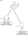
- FIG. 1 is a diagram illustrating a wireless charging system according to an embodiment of the disclosure.
- a wireless charging system 1000 may include an electronic apparatus 100 and at least one external apparatus 200.
- the electronic apparatus 100 and the external apparatus 200 may transmit and receive various signals.
- the external apparatus 200 may transmit, to the electronic apparatus 100, a signal requesting charging of a battery of the external apparatus 200.
- the external apparatus 200 when a user command to request charging of a battery is input, or remaining capacity of a battery is less than or equal to a preset capacity, may transmit, to the electronic apparatus 100, a signal to request charging of a battery.
- the preset capacity may be set in a diverse manner according to a user command.
- the preset capacity can be 10% of a total capacity of the battery.
- the electronic apparatus 100 when a signal to request charging of the battery is received from the external apparatus 200, may transmit, to the external apparatus 200, a signal for charging the battery of the external apparatus 200.
- the electronic apparatus 100 may transmit a radio frequency (RF) signal for charging the battery of the external apparatus 200 to the external apparatus 200.
- RF radio frequency
- the RF signal can be generated by supplying power to the resonance coil provided in the electronic apparatus 100.
- the external apparatus 200 may convert the RF signal received from the electronic apparatus 100 to direct current (DC) and charge the battery of the external apparatus 200.
- DC direct current
- the electronic apparatus 100 has an effect to charge the battery of the external apparatus 200 from a remote distance.
- a user may move the external apparatus 200 in a comparatively free manner.
- the electronic apparatus 100 can transmit an RF signal for charging the battery of the external apparatus 200 toward the external apparatus 200.
- the electronic apparatus 100 may transmit the RF signal toward the external apparatus 200.
- battery of the external apparatus 200 can be charged rapidly and efficiently.
- the external apparatus 200 may be implemented as an earphone 210, a speaker 220, and a smart watch 230, but this is merely exemplary, and the external apparatus 200 may be implemented as various electronic apparatuses capable of transceiving signals with the electronic apparatus 100.
- FIG. 2 is a block diagram illustrating an electronic apparatus according to an embodiment of the disclosure.
- the electronic apparatus 100 may include a directional antenna 110 and a processor 120.
- the directional antenna 110 can transmit and receive signals in a specific direction.
- the directional antenna 110 can transmit signals in a specific direction and receive signals in a specific direction, as opposed to randomly transmitting and receiving signals by the omnidirectional antenna.
- the directional antenna 110 may receive, from the external apparatus 200, a signal to request charging of the battery of the external apparatus 200.
- the directional antenna 110 may receive a signal to request charging of a battery from the external apparatus 200 when a user command to request charging of the battery is input to the external apparatus 200 or remaining capacity of the battery of the external apparatus 200 is less than or equal to a preset capacity.
- the directional antenna 110 may transmit an RF signal toward the external apparatus 200.
- the RF signal is a signal for charging the battery of the external apparatus 200, and the RF signal can be generated by supplying power to the resonance coil provided in the electronic apparatus 100.
- the directional antenna 110 can be implemented as an array antenna and so on.
- the processor 120 controls overall operations of the electronic apparatus.
- the processor 120 may include at least one of a central processing unit (CPU), an application processor (AP), or a communication processor (CP).
- CPU central processing unit
- AP application processor
- CP communication processor
- the processor 120 may receive from the external apparatus 200 a signal to request charging of the battery of the external apparatus 200.
- the processor 120 may receive from the external apparatus 200 a signal to request charging of the battery of the external apparatus 200 through the directional antenna 110.
- the processor 120 may identify the location of the external apparatus 200 based on the intensity and direction of the signal received from the external apparatus 200. To be specific, the processor 120 can identify that the external apparatus 200 is relatively close to the electronic apparatus 100 as the intensity of the signal received from the external apparatus 200 is stronger, and identify that the external apparatus 200 is located in the direction of the signal received from the external apparatus 200.
- the processor 120 may determine the position of the external apparatus 200 in various ways.
- the processor 120 may identify the location of the external apparatus 200 through communication with the beacon.
- the beacon means a device that transmits position information of the external apparatus 200 through a near field wireless communication, such as Bluetooth.
- the processor 120 may also receive information about the location of the external apparatus 200 from the external apparatus 200. Specifically, the processor 120 may receive information about the location of the external apparatus 200 via a near field wireless communication network, such as Wi-Fi, Bluetooth, and the like. To this end, the electronic apparatus 100 may further include a wireless communication chip, such as a Wi-Fi chip or a Bluetooth chip.
- a wireless communication chip such as a Wi-Fi chip or a Bluetooth chip.
- the processor 120 may transmit the RF signal for charging the battery of the external apparatus 200 toward the external apparatus 200 based on the position of the external apparatus 200.
- the processor 120 may control the directional antenna 110 to transmit the RF signal to charge the battery of the external apparatus 200 toward the external apparatus 200. For example, rather than transmitting the RF signal in an omnidirectional manner, the processor 120 may transmit the RF signal toward the external apparatus 200.
- battery of the external apparatus 200 can be charged rapidly and efficiently.
- the RF signal can be generated by supplying power to the resonance coil provided in the electronic apparatus 100.
- processor 120 may generate power by providing power to a resonant coil provided in electronic apparatus 100 to generate a specific frequency.
- the electronic apparatus 100 may charge the battery of the external apparatus 200 remotely located.
- a user may comparatively move and use the external apparatus 200 while charging.
- the processor 120 may stop transmission of the RF signal.
- the processor 120 when the processor 120 receives from the external apparatus 200 information indicating that charging of the battery is completed, power is not provided to the resonance coil in the electronic apparatus 100 anymore, and generation of the RF signal can be stopped. Thus, unnecessary power consumption can be prevented.
- the processor 120 may receive from, a plurality of external apparatus 200, a signal to request charging of the battery included in each external apparatus 200.
- the processor 120 may receive a signal to request charging of the battery of a first external apparatus 210 from the first external apparatus 210 and receive a signal to request charging of a second external apparatus 200 from a second external apparatus 220.
- the processor 120 may sequentially transmit the RF signal to charge the battery to the first external apparatus 210 and the second external apparatus 200.
- the processor 120 may sequentially transmit an RF signal to charge the battery to the first external apparatus 210 and the second external apparatus 220 according to a priority.
- the priority can be set by a user input for each external apparatus 200. For example, when a user input is entered to preferentially charge the first external apparatus 210 to the second external apparatus 220 by a user terminal device that communicates with the electronic apparatus 100, the processor 120 may transmit the RF signal to the first external apparatus 210 in preference to the second external apparatus 220.
- the processor 120 may stop transmitting the RF signal to the first external apparatus 210 and transmit the RF signal to the second external apparatus 220.
- a user may preferentially charge the external apparatus 200 which needs to be charged first.
- the priority can be determined by various methods, in addition to a user input. For example, out of the first external apparatus 210 and the second external apparatus 220, the processor 120 may identify an apparatus having high frequency of use, that is, an apparatus a user frequently uses, and transmit the RF signal first to a frequently used apparatus.
- the frequency of use can be determined based on the past charging history information.
- the processor 120 can identify an apparatus that has been frequently charged based on the charging history information, and can transmit an RF signal first to an apparatus that has been frequently charged.
- the electronic apparatus 100 may further include a storage to store charging history information for each of the external apparatus 200.
- the processor 120 can identify an apparatus having a fast charging speed among the first external apparatus 210 and the second external apparatus 220, and can transmit an RF signal to an apparatus having a fast charging speed first.
- the charging speed can be distinguished based on the charging history information stored in the storage.
- the processor 120 can identify the external apparatus 200 having a fast charging speed based on the charging speed of the external apparatus 200, which is included in the charging history information.
- the processor 120 may transmit the RF signal to charge the battery respectively to the first external apparatus 210 and the second external apparatus 220.
- the processor 120 may charge battery of the first external apparatus 210 and the battery of the second external apparatus 220 at the same time.
- FIG. 3 is a diagram illustrating an operation of an electronic apparatus which receives a signal to request charging of a battery from a plurality of external apparatuses according to an embodiment of the disclosure.
- the processor 120 may receive a signal, from the plurality of external apparatus 200, to request charging of the battery included in each external apparatus 200.
- the processor 120 may receive, from the first external apparatus 210, a signal to request charging of the battery of the first external apparatus 210, and receive, from the second external apparatus 220, a signal to request charging of the battery of the second external apparatus 200.
- the processor 120 may identify intensity of the RF signals which are to be transmitted to each of the first external apparatus 210 and the second external apparatus 200 according to a priority of the first external apparatus 210 and the second external apparatus 220.
- the priority can be set by a user input for each external apparatus 200, or can be determined by a frequency of use of the external apparatus 200 or charging speed of the external apparatus or the like.
- the processor 120 may divide intensity of the RF signal according to priority and transmit the divided RF signal to each of the first external apparatus 210 and the second external apparatus 220.
- the processor 120 may set the intensity of the RF signal to 3:7, transmit the RF signal having the intensity of 30% to the first external apparatus 210, and transmit the RF signal having the intensity of 70% to the second external apparatus 220.
- the processor 120 may divide the RF signal strength into 3:7, transmit the RF signal having the intensity of 30% to the first external apparatus 210, and transmit the RF signal having the intensity of 70% to the second external apparatus 220.
- the user can charge the external apparatus 200 which is required to be charged first.
- the electronic apparatus 100 has the effect of charging a plurality of the external apparatus 200 at the same time.
- the electronic apparatus 100 By transmitting an RF signal toward the external apparatus 200 instead of transmitting an RF signal omnidirectionally, charging efficiency can be improved as well.
- the processor 120 may charge each battery of a plurality of the external apparatus 200 based on the distance between the electronic apparatus 100 and the external apparatus 200. For example, the processor 120 may charge the external apparatus 210, which is at a short distance from the electronic apparatus 100, with a strong charging intensity, and charge the external apparatus 220, which is at a relatively long distance, with a weak charging intensity.
- FIGS. 4A and 4B are diagrams illustrating a method for setting a priority according to various embodiments of the disclosure.
- the electronic apparatus 100 may transceiver various data by communicating with a user terminal apparatus 300.
- the electronic apparatus 100 may further include a wireless communication chip, such as a Wi-Fi chip and a Bluetooth chip.
- the electronic apparatus 100 may transmit, to the user terminal apparatus 300, information on the external apparatus 200 which is to be charged.
- the information on the external apparatus 200 may include information on identification of the external apparatus 200 and remaining capacity of the battery of the external apparatus 200, or the like.
- the electronic apparatus 100 may receive, from the external apparatus 200, information on the external apparatus 200.
- the user terminal apparatus 300 may display a screen for setting a priority of charging by external apparatus 200.
- a user terminal apparatus 300 may display a list of a plurality of the external apparatus 200.
- the selected external apparatus 200 can be set to a charging subject having a priority higher than an external apparatus which is not selected.
- the dragged external apparatus 200 may be set to a subject to be preferentially charged than an external apparatus at a lower side in the list.
- the user terminal apparatus 300 may transmit, to the electronic apparatus 100, information on the set priority.
- the processor 120 may identify the external apparatus 200 set in priority order based on the information received from the user terminal apparatus 300.
- the processor 120 may sequentially transmit, to the plurality of external apparatus 200, the RF signal according to the set priorities.
- the user terminal apparatus 300 may display a screen for setting charging intensities by the plurality of external apparatus 200.
- the user terminal apparatus 300 may set a charging intensity according to a user command that is input to set charging intensity.
- the user terminal apparatus 300 may set charging intensity of the first external apparatus to 50%, charging intensity of the second external apparatus to 30%, and charging intensity of a third external apparatus to 20% according to an input user command.
- the user terminal apparatus may transmit, to the electronic apparatus 100, information on the set charging intensity.
- the processor 120 may identify the charging intensities that are set for the plurality of external apparatus 200 based on the information received from the user terminal apparatus 300.
- the processor 120 can identify the external apparatus 200 having a high charging intensity as the higher priority apparatus 200, and can transmit a strong RF signal.
- the processor 120 may transmit an RF signal having 50% intensity to the first external apparatus, an RF signal having 30% intensity to the second external apparatus, and an RF signal having 20% intensity to the third external apparatus.
- FIG. 5 is a diagram illustrating a user interface (UI) according to an embodiment of the disclosure.
- the electronic apparatus 100 may transmit, to the user terminal apparatus 300, information on an external apparatus.
- the information on the external apparatus 200 may include information on identification of the external apparatus 200, remaining capacity of the battery of the external apparatus 200, and a charging intensity of the external apparatus 200, or the like.
- the processor 120 may receive, from the external apparatus 200, identification information for the external apparatus 200, information about the remaining capacity of the battery of the external apparatus 200, or the like. Specifically, the processor 120 may communicate with the external apparatus 200 and receive information on the identification of the external apparatus 200, the remaining capacity of the battery of the external apparatus 200, or the like.
- the information on the charging intensity may be information corresponding to the intensity of the RF signal which is being transmitted.
- the user terminal apparatus 300 may display a UI including information on the remaining capacity and the charging intensity of the battery for each external apparatus 300 on the display. Accordingly, the user can recognize information on the remaining capacity and the charging intensity of the battery by the external apparatus 200 through the UI displayed on the user terminal apparatus 300.
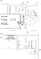
- FIG. 6 is a diagram illustrating guide information according to an embodiment of the disclosure.
- the processor 120 may identify the location of the external apparatus 200 based on the intensity and direction of the signal received from the external apparatus 200. Specifically, the processor 120 can identify that the external apparatus 200 is relatively adjacent to the electronic apparatus 100 as the intensity of the signal received from the external apparatus 200 is stronger, and can identify that the external apparatus 200 is located in the direction of the signal received from the external apparatus 200.
- the processor 120 may provide guide information to let the external apparatus 200 move to a position which is closer than the preset distance.
- the external apparatus 200 When the external apparatus 200 is positioned at a location farther than a preset distance from the electronic apparatus 100, the external apparatus 200 is moved to a closer position to get efficient charging.
- the processor 120 may output a sound to let the external apparatus 200 move to a position closer than a preset distance.
- the electronic apparatus 100 may further include a speaker.
- Outputting a sound by a speaker is merely exemplary, and the processor 120 may display a message to let the external apparatus 200 move, through communication with the user terminal apparatus 300.
- FIG. 7 is a diagram illustrating adjusting of intensity of an RF signal by an electronic apparatus according to an embodiment of the disclosure.
- the processor 120 may adjust the intensity of the RF signal below a predetermined threshold value when the user is sensed between the electronic apparatus 100 and the external apparatus 200.
- the processor 120 may detect electric field corresponding to the human body in a direction where the external apparatus 200 is positioned in operation S710. To do this, the electronic apparatus 100 may further include a sensor that can detect the electric field.
- frequency impedance which is less than 110 when frequency impedance which is less than 110 is detected in a direction where the external apparatus 200 is positioned, it may be identified that a user is present between the electronic apparatus 100 and the external apparatus 200.
- the processor 120 may adjust the intensity of the RF signal to a predetermined threshold or less in operation S720.
- the predetermined threshold value may be an RF signal intensity that is in a degree not to have a harmful influence on the human body.
- a predetermined threshold value may be a value that about 97 mWatt can be provided in a 1 cm x 1 cm space.
- the processor 120 may transmit, to the external apparatus 200, the RF signal that is adjusted to a value that is less than or equal to a preset threshold value in operation S730.
- the electronic apparatus 100 may prevent a wireless signal from having a harmful influence on the human body.
- the electronic apparatus 100 can adjust the intensity of the RF signal to a predetermined threshold value or less when infrared rays generated in the human body are detected near the external apparatus 200 through an infrared sensor.
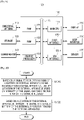
- FIG. 8 is a diagram illustrating an authentication procedure according to an embodiment of the disclosure.
- the processor 120 may transmit, to the external apparatus 200, a signal to request authentication to confirm whether the external apparatus 200 is an authenticated apparatus in operation S810.
- the processor 120 may generate a one-time password (OTP).
- OTP one-time password
- the processor 120 may transmit, to the external apparatus 200, a signal to request authentication to ask input of a password that is the same as the generated password.
- the processor 120 may identify whether the external apparatus 200 is an authenticated apparatus based on the received authentication information in operation S820. Specifically, when the received authentication information, i.e., the received password matches the generated OTP, the processor 120 may identify the external apparatus 200 as an authenticated apparatus.
- the processor 120 may transmit, to the external apparatus 200, an RF signal to charge the battery of the external apparatus 200 in operation S830.
- Identifying whether the external apparatus 200 is an authenticated apparatus using the OTP is merely exemplary, and authentication can be performed by various methods.
- FIG. 9 is a block diagram of an electronic apparatus according to an embodiment of the disclosure.
- an electronic apparatus 100' may include the directional antenna 110, the processor 120, a storage 130, a communicator 140, a display 150, a user interface 160, and a sensor 170.
- the processor 120 may include a random access memory (RAM) 121, a read only memory (ROM) 122, a graphic processor 123, a main CPU 124, a first interface 125-1 through an nth interface 125-n.
- the storage 130 may store an operating system (OS) to control overall operations of components of the electronic apparatus 100' and instructions or data relating to the components of the electronic apparatus 100'.
- OS operating system
- the processor 120 may control a plurality of hardware or software components of the electronic apparatus 100' using various instructions or data stored in the storage 130, load and process instructions or data received from at least one of different components to a transitory memory, and store various data in a non-transitory memory.
- the storage 130 may store charging history information of the external apparatus 200.
- the charging history information may include information on charging frequency of the external apparatus 200 and charging speed of the external apparatus 200 or the like.
- the communicator 140 may communicate with various apparatuses through various communication networks.
- the communicator may communicate with the external apparatus 200 and receive, from the external apparatus 200, information on the identification of the external apparatus 200 and the remaining capacity of the battery of the external apparatus 200, or the like.
- the communicator 140 may communicate with the user terminal apparatus 300 and transmit, to the user terminal apparatus 300, information including identification information of the external apparatus 200 and remaining capacity of the battery of the external apparatus 200, or the like.
- the communicator 140 may receive, from the user terminal apparatus 300, information on charging priority of the external apparatus 200.
- the communicator 140 may include a wireless communication chip, such as a Wi-Fi chip and a Bluetooth chip, or the like.
- the display 150 may display various screens.
- the display 150 may be implemented as various types of displays, such as a liquid crystal display panel (LCD), a light emitting diode (LED), an organic light emitting diode (OLED), a liquid crystal on silicon (LCoS), digital light processing (DLP), or the like.
- a driving circuit, a backlight unit, and the like that can be implemented in the form of an a-si thin film transistor (TFT), a low temperature poly silicon (LTPS) TFT, an organic TFT (OTFT).
- TFT a-si thin film transistor
- LTPS low temperature poly silicon
- OFT organic TFT
- the display 150 may display information about the external apparatus 200 being charged.
- the information on the external apparatus 200 may include information, such as a name of the external apparatus 200, the remaining capacity of the battery of the external apparatus 200, intensity of charging, and so on.
- the display 150 may arrange and display a plurality of the external apparatus 200 based on charging priority.
- priority can be set by a user command or the like which is input to the user terminal apparatus 300 as described above.
- the priority may also be set by a user command inputted through the user interface 160 of an electronic apparatus 100'.
- the user interface 160 may be a physical key provided in the electronic apparatus 100'.
- the display 150 is implemented as a touchpad capable of receiving a user's touch input, the user interface 150 may be a touchpad.
- the sensor 170 may detect electric field around the electronic apparatus 100'. To be specific, the sensor 170 may detect electric field of a direction where the external apparatus 200 is located.
- FIG. 10 is a flowchart illustrating an operation of an electronic apparatus according to an embodiment of the disclosure.
- the electronic apparatus 100 may be configured that when a signal to request charging of battery of the external apparatus 200 is received from the external apparatus 200, the position of the external apparatus 200 can be identified based on the intensity and receiving direction of the signal in operation S1010.
- the electronic apparatus 100 can identify the external apparatus 200 as being relatively close to the electronic apparatus 100 as the intensity of the signal received from the external apparatus 200 is stronger, and can identify that the external apparatus 200 is located in the direction of the signal received from the apparatus 200.
- the electronic apparatus 100 may then transmit a RF signal to the external apparatus 200 to charge the battery of the external apparatus 200 based on the location of the external apparatus 200 in operation S1020.
- the electronic apparatus 100 may transmit an RF signal toward the external apparatus 200.
- the disclosure can charge battery of the external apparatus 200 rapidly and efficiently.
- the electronic apparatus 100 may transmit an RF signal to each of a plurality of the external apparatus 200 when a signal to request charging of the battery is received from a plurality of the external apparatus 200.
- battery of each external apparatus 200 When battery of the plurality of external apparatus 200 is charged, battery of each external apparatus 200 can be charged efficiently without waste of energy.
- Methods according to various embodiments can be implemented as software or application which can be installed in an existing electronic apparatus.
- Methods according to various embodiments can be implemented only by software upgrade or hardware upgrade of an existing electronic apparatus.
- a computer program product comprising one or more computer readable storage media having program which sequentially performs a controlling method of the electronic apparatus according to the embodiment can be provided.
- a non-transitory computer readable medium that stores a program which sequentially performs a controlling method of the electronic apparatus according to the embodiment can be provided.
- Non-transitory computer readable medium means a medium that stores data for a short period of time, such as a register, a cache, a memory, etc., but semi-permanently stores data and can be read by a device.
- Specific examples of non-transitory computer readable media include compact disc (CD), digital versatile disc (DVD), hard disk, Blu-ray disk, universal serial bus (USB), memory card, ROM, and the like.
Landscapes
- Engineering & Computer Science (AREA)
- Power Engineering (AREA)
- Computer Networks & Wireless Communication (AREA)
- Charge And Discharge Circuits For Batteries Or The Like (AREA)
Claims (13)
- Elektronische Vorrichtung (100), welche Folgendes umfasst:eine Richtungsantenne (110); undmindestens einen Prozessor (120), der konfiguriert ist zum:basierend auf einem Signal zum Anfordern des Ladens einer Batterie von mindestens einer externen Vorrichtung (200), das von der mindestens einen externen Vorrichtung (200) über die Richtungsantenne (110) empfangen wird, Identifizieren eines Standorts der mindestens einen externen Vorrichtung (200) basierend auf der Intensität des Signals und einer Richtung, in der das Signal empfangen wird, undSteuern der Richtungsantenne (110), um ein Funkfrequenz(RF)-Signal zum Laden der Batterie der mindestens einen externen Vorrichtung (200) in Richtung der mindestens einen externen Vorrichtung (200) zu übertragen,gekennzeichnet dadurch, dass:
der mindestens eine Prozessor (120) ferner konfiguriert ist, basierend darauf, dass die mindestens eine externe Vorrichtung (200) als an einem Standort positioniert identifiziert wird, der weiter als eine voreingestellte Entfernung von der mindestens einen elektronischen Vorrichtung (100) entfernt ist, basierend auf einem Standort der mindestens einen externen Vorrichtung (120), um Führungsinformationen bereitzustellen, um anzufordern, die mindestens eine externe Vorrichtung (120) zu bewegen, um ein Standort zu sein, der näher als die voreingestellte Entfernung ist. - Elektronische Vorrichtung (100) nach Anspruch 1, wobei die mindestens eine externe Vorrichtung eine erste externe Vorrichtung (200, 210, 220, 230) und eine zweite externe Vorrichtung (200, 210, 220, 230) umfasst, und wobei der mindestens eine Prozessor (120) ferner konfiguriert ist, um, basierend auf Signalen zum Anfordern des Ladens der Batterien der ersten externen Vorrichtung (200, 210, 220, 230) und der zweiten externen Vorrichtung (200, 210, 220, 230), die von der ersten externen Vorrichtung bzw. der zweiten externen Vorrichtung empfangen werden, ein RF-Signal zum Laden einer Batterie der ersten externen Vorrichtung an die erste externe Vorrichtung und ein RF-Signal zum Laden einer Batterie der zweiten externen Vorrichtung an die zweite externe Vorrichtung sequentiell gemäß einer Priorität zu übertragen.
- Elektronische Vorrichtung (100) nach Anspruch 1, wobei die mindestens eine externe Vorrichtung eine erste externe Vorrichtung (200, 210, 220, 230) und eine zweite externe Vorrichtung (200, 210, 220, 230) umfasst, und wobei der mindestens eine Prozessor (120) ferner konfiguriert ist zum:basierend auf Signalen zum Anfordern des Ladens der Batterien der ersten externen Vorrichtung (200, 210, 220, 230) und der zweiten externen Vorrichtung (200, 210, 220, 230), die von der ersten externen Vorrichtung bzw. der zweiten externen Vorrichtung empfangen werden, Identifizieren von Intensitäten des RF-Signals, das sowohl an die erste externe Vorrichtung als auch an die zweite externe Vorrichtung gemäß einer Priorität übertragen werden soll, undÜbertragen eines RF-Signals zum Laden einer Batterie der ersten externen Vorrichtung bzw. einer Batterie der zweiten externen Vorrichtung basierend auf den Intensitäten des RF-Signals an die erste externe Vorrichtung und die zweite externe Vorrichtung.
- Elektronische Vorrichtung (100) nach Anspruch 1, welche ferner Folgendes umfasst:einen Sensor (170),wobei der mindestens eine Prozessor (120) ferner konfiguriert ist, um, basierend darauf, dass ein elektrisches Feld, das einem menschlichen Körper entspricht, von dem Sensor (170) in einer Richtung erkannt wird, in der sich die mindestens eine externe Vorrichtung (200) befindet, die Intensität des RF-Signals einzustellen, das an die mindestens eine externe Vorrichtung (200) übertragen wird, um kleiner als oder gleich einem voreingestellten Schwellenwert zu sein.
- Elektronische Vorrichtung (100) nach Anspruch 1, wobei der mindestens eine Prozessor (120) ferner konfiguriert ist, um Informationen über die Ladeintensität der mindestens einen externen Vorrichtung, die der Intensität des RF-Signals entspricht, und Informationen über die verbleibende Kapazität der Batterie, die von der mindestens einen externen Vorrichtung (200) empfangen werden, an eine Benutzerendgerätvorrichtung zu übertragen.
- Elektronische Vorrichtung (100) nach Anspruch 1, wobei der mindestens eine Prozessor (120) ferner konfiguriert ist, um, basierend auf Informationen, die darüber informieren, dass das Laden der Batterie abgeschlossen ist, die von der mindestens einen externen Vorrichtung (200) empfangen werden, das Übertragen des RF-Signals zu stoppen.
- Elektronische Vorrichtung (100) nach Anspruch 1, wobei der mindestens eine Prozessor (120) ferner konfiguriert ist zum:basierend auf einem Signal zum Anfordern des Ladens der Batterie, das von der mindestens einen externen Vorrichtung (200) empfangen wird, Übertragen eines Authentifizierungsanforderungssignals an die mindestens eine externe Vorrichtung, um zu bestätigen, ob die mindestens eine externe Vorrichtung eine authentifizierte Vorrichtung ist, basierend auf einem Standort der mindestens einen externen Vorrichtung, undbasierend auf Authentifizierungsinformationen, die von der mindestens einen externen Vorrichtung empfangen werden, um auf die Übertragung des Authentifizierungsanforderungssignals zu antworten, Identifizieren, ob die mindestens eine externe Vorrichtung eine authentifizierte Vorrichtung ist, basierend auf den Authentifizierungsinformationen, und wenn die mindestens eine externe Vorrichtung eine authentifizierte Vorrichtung ist, Übertragen des RF-Signals an die externe Vorrichtung.
- Verfahren zum Steuern einer elektronischen Vorrichtung (100) einschließlich mindestens eines Prozessors (120) und einer Richtungsantenne (110), wobei das Verfahren Folgendes umfasst:basierend auf einem Signal zum Anfordern des Ladens einer Batterie von mindestens einer externen Vorrichtung (200), das von der mindestens einen externen Vorrichtung (200) empfangen wird, Identifizieren eines Standorts der mindestens einen externen Vorrichtung (200) durch den mindestens einen Prozessor (120) basierend auf der Intensität des Signals und einer Richtung, in der das Signal empfangen wird; undSteuern der Richtungsantenne (110) durch den mindestens einen Prozessor (120), um ein Funkfrequenz(RF)-Signal zum Laden der Batterie der mindestens einen externen Vorrichtung (200) in Richtung der mindestens einen externen Vorrichtung (200) zu übertragen, basierend auf dem Standort der mindestens einen externen Vorrichtung (200);gekennzeichnet dadurch, dass:
basierend darauf, dass die mindestens eine externe Vorrichtung (200) als an einem Standort positioniert identifiziert wird, der weiter als eine voreingestellte Entfernung von der elektronischen Vorrichtung (100) entfernt ist, basierend auf einem Standort der mindestens einen externen Vorrichtung (200), Führungsinformationen bereitgestellt werden, um anzufordern, die mindestens eine externe Vorrichtung (200) zu bewegen, um ein Standort zu sein, der näher als die voreingestellte Entfernung ist. - Verfahren nach Anspruch 8, wobei die mindestens eine externe Vorrichtung eine erste externe Vorrichtung (200, 210, 220, 230) und eine zweite externe Vorrichtung (200, 210, 220, 230) umfasst und wobei das Übertragen des RF-Signals Folgendes umfasst:
basierend auf Signalen zum Anfordern des Ladens der Batterien der ersten externen Vorrichtung (200, 210, 220, 230) und der zweiten externen Vorrichtung (200, 210, 220, 230), die von der ersten externen Vorrichtung bzw. der zweiten externen Vorrichtung empfangen werden, sequentielles Übertragen eines RF-Signals zum Laden einer Batterie der ersten externen Vorrichtung an die erste externe Vorrichtung und einer Batterie der zweiten externen Vorrichtung an die zweite externe Vorrichtung gemäß einer Priorität. - Verfahren nach Anspruch 8, wobei die mindestens eine externe Vorrichtung eine erste externe Vorrichtung (200, 210, 220, 230) und eine zweite externe Vorrichtung (200, 210, 220, 230) umfasst und wobei das Übertragen des RF-Signals Folgendes umfasst:basierend auf Signalen zum Anfordern des Ladens der Batterien der ersten externen Vorrichtung (200, 210, 220, 230) und der zweiten externen Vorrichtung (200, 210, 220, 230), die von der ersten externen Vorrichtung bzw. der zweiten externen Vorrichtung empfangen werden, Identifizieren von Intensitäten des RF-Signals, das sowohl an die erste externe Vorrichtung als auch an die zweite externe Vorrichtung gemäß einer Priorität übertragen werden soll, undÜbertragen eines RF-Signals zum Laden einer Batterie der ersten externen Vorrichtung bzw. einer Batterie der zweiten externen Vorrichtung basierend auf den Intensitäten des RF-Signals an die erste externe Vorrichtung und die zweite externe Vorrichtung.
- Verfahren nach Anspruch 8, wobei das Übertragen des RF-Signals Folgendes umfasst:Erkennen eines elektrischen Feldes, das einem menschlichen Körper entspricht, in einer Richtung, in der sich die mindestens eine externe Vorrichtung (200) befindet; undEinstellen der Intensität des RF-Signals, das an die mindestens eine externe Vorrichtung übertragen wird, um kleiner als oder gleich einem voreingestellten Schwellenwert zu sein.
- Verfahren nach Anspruch 8, welches ferner Folgendes umfasst:
Übertragen von Informationen über die Ladeintensität der mindestens einen externen Vorrichtung, die der Intensität des RF-Signals entspricht, und von Informationen über die verbleibende Kapazität der Batterie, die von der mindestens einen externem Vorrichtung (200) empfangen werden, an eine Benutzerendgerätvorrichtung. - Verfahren nach Anspruch 8, welches ferner Folgendes umfasst:
basierend auf Informationen, die darüber informieren, dass das Laden der Batterie abgeschlossen ist, die von der mindestens einen externen Vorrichtung (200) empfangen werden, Stoppen des Übertragens des RF-Signals.
Applications Claiming Priority (2)
| Application Number | Priority Date | Filing Date | Title |
|---|---|---|---|
| KR1020180018800A KR102433881B1 (ko) | 2018-02-14 | 2018-02-14 | 전자 장치 및 그 제어 방법 |
| PCT/KR2019/001167 WO2019160256A1 (en) | 2018-02-14 | 2019-01-28 | Electronic apparatus and method for controlling thereof |
Publications (3)
| Publication Number | Publication Date |
|---|---|
| EP3676936A1 EP3676936A1 (de) | 2020-07-08 |
| EP3676936A4 EP3676936A4 (de) | 2020-07-08 |
| EP3676936B1 true EP3676936B1 (de) | 2022-04-20 |
Family
ID=67541185
Family Applications (1)
| Application Number | Title | Priority Date | Filing Date |
|---|---|---|---|
| EP19754571.8A Active EP3676936B1 (de) | 2018-02-14 | 2019-01-28 | Elektronische vorrichtung und verfahren zur steuerung davon |
Country Status (5)
| Country | Link |
|---|---|
| US (1) | US10998749B2 (de) |
| EP (1) | EP3676936B1 (de) |
| KR (1) | KR102433881B1 (de) |
| CN (1) | CN111684683B (de) |
| WO (1) | WO2019160256A1 (de) |
Families Citing this family (4)
| Publication number | Priority date | Publication date | Assignee | Title |
|---|---|---|---|---|
| CN112787387A (zh) * | 2019-11-04 | 2021-05-11 | 北京小米移动软件有限公司 | 无线充电接收设备和电子设备 |
| CN112787417A (zh) | 2019-11-04 | 2021-05-11 | 北京小米移动软件有限公司 | 无线能量发射装置、无线能量接收装置、无线供能方法及系统 |
| CN113872336B (zh) * | 2021-09-29 | 2025-02-11 | 维沃移动通信有限公司 | 充电设备和充电方法 |
| KR20240092265A (ko) * | 2022-12-14 | 2024-06-24 | 삼성전자주식회사 | 무선 전력 송신 장치 및 그 동작 방법 |
Family Cites Families (31)
| Publication number | Priority date | Publication date | Assignee | Title |
|---|---|---|---|---|
| US7400253B2 (en) | 2005-08-04 | 2008-07-15 | Mhcmos, Llc | Harvesting ambient radio frequency electromagnetic energy for powering wireless electronic devices, sensors and sensor networks and applications thereof |
| US8447234B2 (en) | 2006-01-18 | 2013-05-21 | Qualcomm Incorporated | Method and system for powering an electronic device via a wireless link |
| US7728551B2 (en) | 2007-04-26 | 2010-06-01 | Visteon Global Technologies, Inc. | Wireless power transfer system |
| KR101425678B1 (ko) | 2007-09-12 | 2014-07-31 | 엘지전자 주식회사 | 무접점 충전 시스템 |
| US8026466B2 (en) * | 2008-09-30 | 2011-09-27 | The Invention Science Fund I | Beam power with receiver impingement detection |
| JP5239706B2 (ja) * | 2008-09-30 | 2013-07-17 | 富士通株式会社 | 充電装置及び充電方法 |
| US20100164433A1 (en) | 2008-12-30 | 2010-07-01 | Motorola, Inc. | Wireless Battery Charging Systems, Battery Systems and Charging Apparatus |
| KR20160145841A (ko) | 2009-11-17 | 2016-12-20 | 애플 인크. | 로컬 컴퓨팅 환경에서의 무선 전력 이용 |
| KR20180004296A (ko) * | 2010-11-23 | 2018-01-10 | 애플 인크. | 로컬 컴퓨팅 환경 내의 무선 전력 이용 |
| KR101736284B1 (ko) | 2010-12-17 | 2017-05-16 | 한국전자통신연구원 | 초음파를 이용한 무선 전력 전송 시스템 |
| US9106106B2 (en) * | 2011-03-18 | 2015-08-11 | Qualcomm Incorporated | Method and apparatus for locating a portable device and then transmitting power over wireless signal |
| KR101768723B1 (ko) * | 2011-03-30 | 2017-08-17 | 삼성전자주식회사 | 휴대단말기의 무선 충전 방법 및 시스템 |
| KR101392866B1 (ko) | 2012-05-25 | 2014-05-09 | 전자부품연구원 | 에너지 존 운영을 위한 무선 전력 전송 시스템 |
| US9184620B2 (en) | 2012-06-28 | 2015-11-10 | Nokia Technologies Oy | Method and apparatus for improved wireless charging efficiency |
| US10063105B2 (en) * | 2013-07-11 | 2018-08-28 | Energous Corporation | Proximity transmitters for wireless power charging systems |
| US9900057B2 (en) * | 2012-07-06 | 2018-02-20 | Energous Corporation | Systems and methods for assigning groups of antenas of a wireless power transmitter to different wireless power receivers, and determining effective phases to use for wirelessly transmitting power using the assigned groups of antennas |
| US9252628B2 (en) * | 2013-05-10 | 2016-02-02 | Energous Corporation | Laptop computer as a transmitter for wireless charging |
| US20160013677A1 (en) * | 2014-07-14 | 2016-01-14 | Energous Corporation | System and Method for Enabling Automatic Charging Schedules in a Wireless Power Network to One or More Devices |
| KR20140059492A (ko) * | 2012-11-08 | 2014-05-16 | 삼성전자주식회사 | 휴대 단말기에서 무선 충전 장치의 위치를 출력하는 장치 및 방법 |
| US9525311B2 (en) * | 2013-09-05 | 2016-12-20 | Nirvanalog Inc. | Wireless power transmission in portable communication devices |
| KR101561938B1 (ko) * | 2013-12-30 | 2015-10-20 | 전자부품연구원 | 무선 전력 송수신기의 거리 측정 방법 및 이를 수행하는 무선 전력 전송 시스템 |
| US9837712B2 (en) * | 2014-09-19 | 2017-12-05 | Qorvo Us, Inc. | Antenna array calibration for wireless charging |
| US9564773B2 (en) * | 2014-09-24 | 2017-02-07 | Intel IP Corportation | Methods and systems for optimizing location-based wireless charging |
| DE102014223328A1 (de) | 2014-11-14 | 2016-05-19 | Fraunhofer-Gesellschaft zur Förderung der angewandten Forschung e.V. | Antennenvorrichtung, Funkerkennungssystem und Verfahren zum Aussenden eines Funksignals |
| CN105099003A (zh) * | 2015-07-28 | 2015-11-25 | 联想(北京)有限公司 | 一种无线充电方法及对应装置 |
| CN105449786B (zh) * | 2015-12-31 | 2019-02-05 | 联想(北京)有限公司 | 一种信息处理方法及电子设备 |
| KR102492190B1 (ko) * | 2016-01-11 | 2023-01-27 | 삼성전자주식회사 | 무선 전력 전송 장치, 무선 충전 시스템 및 이들의 제어 방법 |
| CN105762946B (zh) * | 2016-04-08 | 2018-10-16 | 电子科技大学 | 一种基于射频接收和相位补偿转发的无线充电方法及装置 |
| EP3244542B1 (de) * | 2016-05-09 | 2019-07-24 | Intel IP Corporation | Verfahren und vorrichtung zur interferenzreduzierung in einem drahtlos-ladesignal |
| US11183885B2 (en) | 2016-05-13 | 2021-11-23 | Samsung Electronics Co., Ltd. | Wireless power transmission device and control method thereof |
| TWI679826B (zh) * | 2016-06-10 | 2019-12-11 | 美商歐西亞股份有限公司 | 用於近場及遠場應用的無線電力傳輸的方法和設備 |
-
2018
- 2018-02-14 KR KR1020180018800A patent/KR102433881B1/ko active Active
-
2019
- 2019-01-28 WO PCT/KR2019/001167 patent/WO2019160256A1/en not_active Ceased
- 2019-01-28 EP EP19754571.8A patent/EP3676936B1/de active Active
- 2019-01-28 CN CN201980011650.7A patent/CN111684683B/zh active Active
- 2019-02-11 US US16/272,512 patent/US10998749B2/en active Active
Also Published As
| Publication number | Publication date |
|---|---|
| US10998749B2 (en) | 2021-05-04 |
| WO2019160256A1 (en) | 2019-08-22 |
| CN111684683B (zh) | 2023-12-12 |
| KR102433881B1 (ko) | 2022-08-19 |
| EP3676936A1 (de) | 2020-07-08 |
| KR20190098632A (ko) | 2019-08-22 |
| CN111684683A (zh) | 2020-09-18 |
| EP3676936A4 (de) | 2020-07-08 |
| US20190252899A1 (en) | 2019-08-15 |
Similar Documents
| Publication | Publication Date | Title |
|---|---|---|
| US11489368B2 (en) | Electronic device and method for wireless charging in electronic device | |
| EP3676936B1 (de) | Elektronische vorrichtung und verfahren zur steuerung davon | |
| EP3430703B1 (de) | Drahtloses laden | |
| EP3588343B1 (de) | Mobile computervorrichtung und tragbare computervorrichtung mit automatischer zugangsmodussteuerung | |
| US11120424B2 (en) | Systems and methods for providing near field communications | |
| KR101902795B1 (ko) | 무선 충전 장치 및 방법 | |
| US9699602B2 (en) | Peripheral apparatus, server apparatus and method for determining location of portable apparatus | |
| KR102112353B1 (ko) | 안테나 방사 전력 제어 방법 및 이를 지원하는 전자 장치 | |
| US10050477B2 (en) | Power transmission device, control method for power transmission device, and storage medium | |
| CN108513274B (zh) | 用于控制车辆的电子设备及其操作方法 | |
| US20160087484A1 (en) | Wireless charging apparatus | |
| CN104145402A (zh) | 调制无线电力传输信号的方法 | |
| CN106877528A (zh) | 无线电力接收器和用于控制该无线电力接收器的方法 | |
| US10963654B2 (en) | Electronic device for transmitting data and method for controlling the same | |
| US20150349852A1 (en) | Electronic device having multiple subscriber identity modules and method therefor | |
| KR20190122392A (ko) | 근거리 통신을 이용하여 디바이스들을 페어링하는 방법 및 이를 사용하는 전자 장치 | |
| US20210090055A1 (en) | Electronic device for selectively using coils supporting power sharing | |
| EP4365771A2 (de) | Verfahren zur verringerung des stromverbrauchs in nahfeldkommunikationssystemen | |
| KR20150050200A (ko) | 출력 데이터 제어 방법 및 그 전자 장치 | |
| KR102245194B1 (ko) | 전자 장치 및 전자 장치를 인식하는 방법 | |
| CN109219016B (zh) | 无线通信系统、车辆、智能设备及其控制方法 | |
| KR102829636B1 (ko) | 전자 장치와 전자 장치에 결합되는 커버 액세서리의 동작 방법, 및 커버 액세서리 | |
| KR20190138463A (ko) | 복수의 nfc 동작 모드를 지원하는 전자 장치 및 전자 장치의 동작 방법 | |
| CN119696085A (zh) | 用于在无线充电系统中传送能力的技术 | |
| HK40106331A (zh) | 降低近场通信系统中功耗的技术 |
Legal Events
| Date | Code | Title | Description |
|---|---|---|---|
| STAA | Information on the status of an ep patent application or granted ep patent |
Free format text: STATUS: THE INTERNATIONAL PUBLICATION HAS BEEN MADE |
|
| PUAI | Public reference made under article 153(3) epc to a published international application that has entered the european phase |
Free format text: ORIGINAL CODE: 0009012 |
|
| STAA | Information on the status of an ep patent application or granted ep patent |
Free format text: STATUS: REQUEST FOR EXAMINATION WAS MADE |
|
| 17P | Request for examination filed |
Effective date: 20200331 |
|
| A4 | Supplementary search report drawn up and despatched |
Effective date: 20200421 |
|
| AK | Designated contracting states |
Kind code of ref document: A1 Designated state(s): AL AT BE BG CH CY CZ DE DK EE ES FI FR GB GR HR HU IE IS IT LI LT LU LV MC MK MT NL NO PL PT RO RS SE SI SK SM TR |
|
| AX | Request for extension of the european patent |
Extension state: BA ME |
|
| STAA | Information on the status of an ep patent application or granted ep patent |
Free format text: STATUS: EXAMINATION IS IN PROGRESS |
|
| 17Q | First examination report despatched |
Effective date: 20200925 |
|
| DAV | Request for validation of the european patent (deleted) | ||
| DAX | Request for extension of the european patent (deleted) | ||
| GRAP | Despatch of communication of intention to grant a patent |
Free format text: ORIGINAL CODE: EPIDOSNIGR1 |
|
| STAA | Information on the status of an ep patent application or granted ep patent |
Free format text: STATUS: GRANT OF PATENT IS INTENDED |
|
| INTG | Intention to grant announced |
Effective date: 20220201 |
|
| GRAS | Grant fee paid |
Free format text: ORIGINAL CODE: EPIDOSNIGR3 |
|
| GRAA | (expected) grant |
Free format text: ORIGINAL CODE: 0009210 |
|
| STAA | Information on the status of an ep patent application or granted ep patent |
Free format text: STATUS: THE PATENT HAS BEEN GRANTED |
|
| AK | Designated contracting states |
Kind code of ref document: B1 Designated state(s): AL AT BE BG CH CY CZ DE DK EE ES FI FR GB GR HR HU IE IS IT LI LT LU LV MC MK MT NL NO PL PT RO RS SE SI SK SM TR |
|
| REG | Reference to a national code |
Ref country code: GB Ref legal event code: FG4D |
|
| REG | Reference to a national code |
Ref country code: CH Ref legal event code: EP |
|
| REG | Reference to a national code |
Ref country code: DE Ref legal event code: R096 Ref document number: 602019013950 Country of ref document: DE |
|
| REG | Reference to a national code |
Ref country code: IE Ref legal event code: FG4D |
|
| REG | Reference to a national code |
Ref country code: AT Ref legal event code: REF Ref document number: 1485965 Country of ref document: AT Kind code of ref document: T Effective date: 20220515 |
|
| REG | Reference to a national code |
Ref country code: LT Ref legal event code: MG9D |
|
| REG | Reference to a national code |
Ref country code: NL Ref legal event code: MP Effective date: 20220420 |
|
| REG | Reference to a national code |
Ref country code: AT Ref legal event code: MK05 Ref document number: 1485965 Country of ref document: AT Kind code of ref document: T Effective date: 20220420 |
|
| PG25 | Lapsed in a contracting state [announced via postgrant information from national office to epo] |
Ref country code: NL Free format text: LAPSE BECAUSE OF FAILURE TO SUBMIT A TRANSLATION OF THE DESCRIPTION OR TO PAY THE FEE WITHIN THE PRESCRIBED TIME-LIMIT Effective date: 20220420 |
|
| PG25 | Lapsed in a contracting state [announced via postgrant information from national office to epo] |
Ref country code: SE Free format text: LAPSE BECAUSE OF FAILURE TO SUBMIT A TRANSLATION OF THE DESCRIPTION OR TO PAY THE FEE WITHIN THE PRESCRIBED TIME-LIMIT Effective date: 20220420 Ref country code: PT Free format text: LAPSE BECAUSE OF FAILURE TO SUBMIT A TRANSLATION OF THE DESCRIPTION OR TO PAY THE FEE WITHIN THE PRESCRIBED TIME-LIMIT Effective date: 20220822 Ref country code: NO Free format text: LAPSE BECAUSE OF FAILURE TO SUBMIT A TRANSLATION OF THE DESCRIPTION OR TO PAY THE FEE WITHIN THE PRESCRIBED TIME-LIMIT Effective date: 20220720 Ref country code: LT Free format text: LAPSE BECAUSE OF FAILURE TO SUBMIT A TRANSLATION OF THE DESCRIPTION OR TO PAY THE FEE WITHIN THE PRESCRIBED TIME-LIMIT Effective date: 20220420 Ref country code: HR Free format text: LAPSE BECAUSE OF FAILURE TO SUBMIT A TRANSLATION OF THE DESCRIPTION OR TO PAY THE FEE WITHIN THE PRESCRIBED TIME-LIMIT Effective date: 20220420 Ref country code: GR Free format text: LAPSE BECAUSE OF FAILURE TO SUBMIT A TRANSLATION OF THE DESCRIPTION OR TO PAY THE FEE WITHIN THE PRESCRIBED TIME-LIMIT Effective date: 20220721 Ref country code: FI Free format text: LAPSE BECAUSE OF FAILURE TO SUBMIT A TRANSLATION OF THE DESCRIPTION OR TO PAY THE FEE WITHIN THE PRESCRIBED TIME-LIMIT Effective date: 20220420 Ref country code: ES Free format text: LAPSE BECAUSE OF FAILURE TO SUBMIT A TRANSLATION OF THE DESCRIPTION OR TO PAY THE FEE WITHIN THE PRESCRIBED TIME-LIMIT Effective date: 20220420 Ref country code: BG Free format text: LAPSE BECAUSE OF FAILURE TO SUBMIT A TRANSLATION OF THE DESCRIPTION OR TO PAY THE FEE WITHIN THE PRESCRIBED TIME-LIMIT Effective date: 20220720 Ref country code: AT Free format text: LAPSE BECAUSE OF FAILURE TO SUBMIT A TRANSLATION OF THE DESCRIPTION OR TO PAY THE FEE WITHIN THE PRESCRIBED TIME-LIMIT Effective date: 20220420 |
|
| PG25 | Lapsed in a contracting state [announced via postgrant information from national office to epo] |
Ref country code: RS Free format text: LAPSE BECAUSE OF FAILURE TO SUBMIT A TRANSLATION OF THE DESCRIPTION OR TO PAY THE FEE WITHIN THE PRESCRIBED TIME-LIMIT Effective date: 20220420 Ref country code: PL Free format text: LAPSE BECAUSE OF FAILURE TO SUBMIT A TRANSLATION OF THE DESCRIPTION OR TO PAY THE FEE WITHIN THE PRESCRIBED TIME-LIMIT Effective date: 20220420 Ref country code: LV Free format text: LAPSE BECAUSE OF FAILURE TO SUBMIT A TRANSLATION OF THE DESCRIPTION OR TO PAY THE FEE WITHIN THE PRESCRIBED TIME-LIMIT Effective date: 20220420 Ref country code: IS Free format text: LAPSE BECAUSE OF FAILURE TO SUBMIT A TRANSLATION OF THE DESCRIPTION OR TO PAY THE FEE WITHIN THE PRESCRIBED TIME-LIMIT Effective date: 20220820 |
|
| REG | Reference to a national code |
Ref country code: DE Ref legal event code: R097 Ref document number: 602019013950 Country of ref document: DE |
|
| PG25 | Lapsed in a contracting state [announced via postgrant information from national office to epo] |
Ref country code: SM Free format text: LAPSE BECAUSE OF FAILURE TO SUBMIT A TRANSLATION OF THE DESCRIPTION OR TO PAY THE FEE WITHIN THE PRESCRIBED TIME-LIMIT Effective date: 20220420 Ref country code: SK Free format text: LAPSE BECAUSE OF FAILURE TO SUBMIT A TRANSLATION OF THE DESCRIPTION OR TO PAY THE FEE WITHIN THE PRESCRIBED TIME-LIMIT Effective date: 20220420 Ref country code: RO Free format text: LAPSE BECAUSE OF FAILURE TO SUBMIT A TRANSLATION OF THE DESCRIPTION OR TO PAY THE FEE WITHIN THE PRESCRIBED TIME-LIMIT Effective date: 20220420 Ref country code: EE Free format text: LAPSE BECAUSE OF FAILURE TO SUBMIT A TRANSLATION OF THE DESCRIPTION OR TO PAY THE FEE WITHIN THE PRESCRIBED TIME-LIMIT Effective date: 20220420 Ref country code: DK Free format text: LAPSE BECAUSE OF FAILURE TO SUBMIT A TRANSLATION OF THE DESCRIPTION OR TO PAY THE FEE WITHIN THE PRESCRIBED TIME-LIMIT Effective date: 20220420 Ref country code: CZ Free format text: LAPSE BECAUSE OF FAILURE TO SUBMIT A TRANSLATION OF THE DESCRIPTION OR TO PAY THE FEE WITHIN THE PRESCRIBED TIME-LIMIT Effective date: 20220420 |
|
| PGFP | Annual fee paid to national office [announced via postgrant information from national office to epo] |
Ref country code: GB Payment date: 20221220 Year of fee payment: 5 |
|
| PLBE | No opposition filed within time limit |
Free format text: ORIGINAL CODE: 0009261 |
|
| STAA | Information on the status of an ep patent application or granted ep patent |
Free format text: STATUS: NO OPPOSITION FILED WITHIN TIME LIMIT |
|
| 26N | No opposition filed |
Effective date: 20230123 |
|
| PG25 | Lapsed in a contracting state [announced via postgrant information from national office to epo] |
Ref country code: AL Free format text: LAPSE BECAUSE OF FAILURE TO SUBMIT A TRANSLATION OF THE DESCRIPTION OR TO PAY THE FEE WITHIN THE PRESCRIBED TIME-LIMIT Effective date: 20220420 |
|
| PG25 | Lapsed in a contracting state [announced via postgrant information from national office to epo] |
Ref country code: SI Free format text: LAPSE BECAUSE OF FAILURE TO SUBMIT A TRANSLATION OF THE DESCRIPTION OR TO PAY THE FEE WITHIN THE PRESCRIBED TIME-LIMIT Effective date: 20220420 |
|
| PGFP | Annual fee paid to national office [announced via postgrant information from national office to epo] |
Ref country code: DE Payment date: 20221220 Year of fee payment: 5 |
|
| REG | Reference to a national code |
Ref country code: CH Ref legal event code: PL |
|
| PG25 | Lapsed in a contracting state [announced via postgrant information from national office to epo] |
Ref country code: LU Free format text: LAPSE BECAUSE OF NON-PAYMENT OF DUE FEES Effective date: 20230128 |
|
| REG | Reference to a national code |
Ref country code: BE Ref legal event code: MM Effective date: 20230131 |
|
| PG25 | Lapsed in a contracting state [announced via postgrant information from national office to epo] |
Ref country code: LI Free format text: LAPSE BECAUSE OF NON-PAYMENT OF DUE FEES Effective date: 20230131 Ref country code: CH Free format text: LAPSE BECAUSE OF NON-PAYMENT OF DUE FEES Effective date: 20230131 |
|
| PG25 | Lapsed in a contracting state [announced via postgrant information from national office to epo] |
Ref country code: FR Free format text: LAPSE BECAUSE OF NON-PAYMENT OF DUE FEES Effective date: 20230131 Ref country code: BE Free format text: LAPSE BECAUSE OF NON-PAYMENT OF DUE FEES Effective date: 20230131 |
|
| PG25 | Lapsed in a contracting state [announced via postgrant information from national office to epo] |
Ref country code: IT Free format text: LAPSE BECAUSE OF FAILURE TO SUBMIT A TRANSLATION OF THE DESCRIPTION OR TO PAY THE FEE WITHIN THE PRESCRIBED TIME-LIMIT Effective date: 20220420 Ref country code: IE Free format text: LAPSE BECAUSE OF NON-PAYMENT OF DUE FEES Effective date: 20230128 |
|
| PG25 | Lapsed in a contracting state [announced via postgrant information from national office to epo] |
Ref country code: MC Free format text: LAPSE BECAUSE OF FAILURE TO SUBMIT A TRANSLATION OF THE DESCRIPTION OR TO PAY THE FEE WITHIN THE PRESCRIBED TIME-LIMIT Effective date: 20220420 |
|
| PG25 | Lapsed in a contracting state [announced via postgrant information from national office to epo] |
Ref country code: MC Free format text: LAPSE BECAUSE OF FAILURE TO SUBMIT A TRANSLATION OF THE DESCRIPTION OR TO PAY THE FEE WITHIN THE PRESCRIBED TIME-LIMIT Effective date: 20220420 |
|
| REG | Reference to a national code |
Ref country code: DE Ref legal event code: R119 Ref document number: 602019013950 Country of ref document: DE |
|
| GBPC | Gb: european patent ceased through non-payment of renewal fee |
Effective date: 20240128 |
|
| PG25 | Lapsed in a contracting state [announced via postgrant information from national office to epo] |
Ref country code: DE Free format text: LAPSE BECAUSE OF NON-PAYMENT OF DUE FEES Effective date: 20240801 |
|
| PG25 | Lapsed in a contracting state [announced via postgrant information from national office to epo] |
Ref country code: GB Free format text: LAPSE BECAUSE OF NON-PAYMENT OF DUE FEES Effective date: 20240128 |
|
| PG25 | Lapsed in a contracting state [announced via postgrant information from national office to epo] |
Ref country code: GB Free format text: LAPSE BECAUSE OF NON-PAYMENT OF DUE FEES Effective date: 20240128 Ref country code: DE Free format text: LAPSE BECAUSE OF NON-PAYMENT OF DUE FEES Effective date: 20240801 |
|
| PG25 | Lapsed in a contracting state [announced via postgrant information from national office to epo] |
Ref country code: BG Free format text: LAPSE BECAUSE OF FAILURE TO SUBMIT A TRANSLATION OF THE DESCRIPTION OR TO PAY THE FEE WITHIN THE PRESCRIBED TIME-LIMIT Effective date: 20220420 |
|
| PG25 | Lapsed in a contracting state [announced via postgrant information from national office to epo] |
Ref country code: BG Free format text: LAPSE BECAUSE OF FAILURE TO SUBMIT A TRANSLATION OF THE DESCRIPTION OR TO PAY THE FEE WITHIN THE PRESCRIBED TIME-LIMIT Effective date: 20220420 |
|
| PG25 | Lapsed in a contracting state [announced via postgrant information from national office to epo] |
Ref country code: CY Free format text: LAPSE BECAUSE OF FAILURE TO SUBMIT A TRANSLATION OF THE DESCRIPTION OR TO PAY THE FEE WITHIN THE PRESCRIBED TIME-LIMIT; INVALID AB INITIO Effective date: 20190128 |
|
| PG25 | Lapsed in a contracting state [announced via postgrant information from national office to epo] |
Ref country code: HU Free format text: LAPSE BECAUSE OF FAILURE TO SUBMIT A TRANSLATION OF THE DESCRIPTION OR TO PAY THE FEE WITHIN THE PRESCRIBED TIME-LIMIT; INVALID AB INITIO Effective date: 20190128 |
|
| PG25 | Lapsed in a contracting state [announced via postgrant information from national office to epo] |
Ref country code: TR Free format text: LAPSE BECAUSE OF FAILURE TO SUBMIT A TRANSLATION OF THE DESCRIPTION OR TO PAY THE FEE WITHIN THE PRESCRIBED TIME-LIMIT Effective date: 20220420 |