EP3676951B1 - Commande d'un moteur de ventilateur pour l'amélioration de la compatibilité électromagnétique - Google Patents
Commande d'un moteur de ventilateur pour l'amélioration de la compatibilité électromagnétique Download PDFInfo
- Publication number
- EP3676951B1 EP3676951B1 EP18759945.1A EP18759945A EP3676951B1 EP 3676951 B1 EP3676951 B1 EP 3676951B1 EP 18759945 A EP18759945 A EP 18759945A EP 3676951 B1 EP3676951 B1 EP 3676951B1
- Authority
- EP
- European Patent Office
- Prior art keywords
- motor
- rotor
- tist
- rotor speed
- speed
- Prior art date
- Legal status (The legal status is an assumption and is not a legal conclusion. Google has not performed a legal analysis and makes no representation as to the accuracy of the status listed.)
- Active
Links
Images

Classifications
-
- H—ELECTRICITY
- H02—GENERATION; CONVERSION OR DISTRIBUTION OF ELECTRIC POWER
- H02P—CONTROL OR REGULATION OF ELECTRIC MOTORS, ELECTRIC GENERATORS OR DYNAMO-ELECTRIC CONVERTERS; CONTROLLING TRANSFORMERS, REACTORS OR CHOKE COILS
- H02P3/00—Arrangements for stopping or slowing electric motors, generators, or dynamo-electric converters
- H02P3/06—Arrangements for stopping or slowing electric motors, generators, or dynamo-electric converters for stopping or slowing an individual dynamo-electric motor or dynamo-electric converter
- H02P3/08—Arrangements for stopping or slowing electric motors, generators, or dynamo-electric converters for stopping or slowing an individual dynamo-electric motor or dynamo-electric converter for stopping or slowing a DC motor
- H02P3/12—Arrangements for stopping or slowing electric motors, generators, or dynamo-electric converters for stopping or slowing an individual dynamo-electric motor or dynamo-electric converter for stopping or slowing a DC motor by short-circuit or resistive braking
-
- H—ELECTRICITY
- H02—GENERATION; CONVERSION OR DISTRIBUTION OF ELECTRIC POWER
- H02P—CONTROL OR REGULATION OF ELECTRIC MOTORS, ELECTRIC GENERATORS OR DYNAMO-ELECTRIC CONVERTERS; CONTROLLING TRANSFORMERS, REACTORS OR CHOKE COILS
- H02P7/00—Arrangements for regulating or controlling the speed or torque of electric DC motors
- H02P7/06—Arrangements for regulating or controlling the speed or torque of electric DC motors for regulating or controlling an individual DC dynamo-electric motor by varying field or armature current
- H02P7/18—Arrangements for regulating or controlling the speed or torque of electric DC motors for regulating or controlling an individual DC dynamo-electric motor by varying field or armature current by master control with auxiliary power
- H02P7/24—Arrangements for regulating or controlling the speed or torque of electric DC motors for regulating or controlling an individual DC dynamo-electric motor by varying field or armature current by master control with auxiliary power using discharge tubes or semiconductor devices
- H02P7/28—Arrangements for regulating or controlling the speed or torque of electric DC motors for regulating or controlling an individual DC dynamo-electric motor by varying field or armature current by master control with auxiliary power using discharge tubes or semiconductor devices using semiconductor devices
- H02P7/285—Arrangements for regulating or controlling the speed or torque of electric DC motors for regulating or controlling an individual DC dynamo-electric motor by varying field or armature current by master control with auxiliary power using discharge tubes or semiconductor devices using semiconductor devices controlling armature supply only
- H02P7/29—Arrangements for regulating or controlling the speed or torque of electric DC motors for regulating or controlling an individual DC dynamo-electric motor by varying field or armature current by master control with auxiliary power using discharge tubes or semiconductor devices using semiconductor devices controlling armature supply only using pulse modulation
-
- H—ELECTRICITY
- H02—GENERATION; CONVERSION OR DISTRIBUTION OF ELECTRIC POWER
- H02P—CONTROL OR REGULATION OF ELECTRIC MOTORS, ELECTRIC GENERATORS OR DYNAMO-ELECTRIC CONVERTERS; CONTROLLING TRANSFORMERS, REACTORS OR CHOKE COILS
- H02P29/00—Arrangements for regulating or controlling electric motors, appropriate for both AC and DC motors
- H02P29/50—Reduction of harmonics
-
- H—ELECTRICITY
- H02—GENERATION; CONVERSION OR DISTRIBUTION OF ELECTRIC POWER
- H02P—CONTROL OR REGULATION OF ELECTRIC MOTORS, ELECTRIC GENERATORS OR DYNAMO-ELECTRIC CONVERTERS; CONTROLLING TRANSFORMERS, REACTORS OR CHOKE COILS
- H02P3/00—Arrangements for stopping or slowing electric motors, generators, or dynamo-electric converters
- H02P3/06—Arrangements for stopping or slowing electric motors, generators, or dynamo-electric converters for stopping or slowing an individual dynamo-electric motor or dynamo-electric converter
- H02P3/08—Arrangements for stopping or slowing electric motors, generators, or dynamo-electric converters for stopping or slowing an individual dynamo-electric motor or dynamo-electric converter for stopping or slowing a DC motor
-
- H—ELECTRICITY
- H02—GENERATION; CONVERSION OR DISTRIBUTION OF ELECTRIC POWER
- H02P—CONTROL OR REGULATION OF ELECTRIC MOTORS, ELECTRIC GENERATORS OR DYNAMO-ELECTRIC CONVERTERS; CONTROLLING TRANSFORMERS, REACTORS OR CHOKE COILS
- H02P6/00—Arrangements for controlling synchronous motors or other dynamo-electric motors using electronic commutation dependent on the rotor position; Electronic commutators therefor
- H02P6/26—Arrangements for controlling single phase motors
-
- H—ELECTRICITY
- H02—GENERATION; CONVERSION OR DISTRIBUTION OF ELECTRIC POWER
- H02P—CONTROL OR REGULATION OF ELECTRIC MOTORS, ELECTRIC GENERATORS OR DYNAMO-ELECTRIC CONVERTERS; CONTROLLING TRANSFORMERS, REACTORS OR CHOKE COILS
- H02P7/00—Arrangements for regulating or controlling the speed or torque of electric DC motors
- H02P7/03—Arrangements for regulating or controlling the speed or torque of electric DC motors for controlling the direction of rotation of DC motors
- H02P7/04—Arrangements for regulating or controlling the speed or torque of electric DC motors for controlling the direction of rotation of DC motors by means of a H-bridge circuit
Definitions
- DE 10 2015 012540 A1 relates to a method for operating a steering system for a motor vehicle, which comprises an electrical machine with several phases, it being provided that the phases are controlled in a continuous operation while carrying out standard pulse width modulation via pulse width modulated signals of a first electrical quantity, in which case that a fault is diagnosed for the steering system, at least one phase is controlled by carrying out an emergency pulse width modulation via pulse width modulated signals of the electrical quantity.
- a DC motor maintains a constant preset speed under load changes, wherein the preset speed can be changed manually.
- the system includes an AC power source with a conventional bridge rectifier using thyristors and diodes, with means for controlling the phase of firing of the thyristors depending on the engine speed compared to a speed setting.
- US 2005/174081 A1 discloses a multi-stage dynamic braking resistor network including a plurality of dynamic braking resistors for dissipating regenerative energy as heat input to a system bus by a motor or actuator, and a plurality of switches for connecting the dynamic braking resistors.
- the object of the present invention is to provide a method for electrically controlling a motor, in particular a fan motor, with several winding strands, which, on the one hand, improves the EMC behavior of the fan motor compared to fan motors known in the prior art, but at the same time reduces the noise caused by the rotation of the motor must be kept low.
- a method for electrically controlling a motor, in particular a fan motor, with a plurality of winding strands is provided for this purpose, the motor having at least one means for detecting a rotor speed and/or for detecting a rotor position of a rotor of the motor.
- the individual winding strands are alternately supplied with current pulses using the motor's control electronics.
- no current pulse is supplied to at least one of the winding phases during a full revolution of the rotor if the detected rotor speed (T ist ) is greater than a predetermined target speed (T target ).
- the method is preferably intended for an external rotor motor and a brushless motor.
- the individual winding strands are preferably windings of the stator. Alternating current supply to the winding strands means that successive current pulses are supplied to the individual winding strands. A full revolution of the rotor means a revolution of 360°.
- Interrupting the power supply during a full revolution of the rotor is also referred to as slot shutdown in the context of the invention. This means that no current or current pulse is supplied to at least one winding phase, at least during a commutation phase.
- the method according to the invention therefore provides that the actual speed of the rotor or the current rotor speed is measured regularly, is compared with a predetermined target speed (T target ) and the current pulse is suspended in a subsequent commutation phase if the difference reaches a predetermined threshold or size exceeds or if the actual speed (T is ) is greater than the specified target speed (T should ).
- the motor also has at least one means for detecting a rotor speed (T is ) and/or a rotor position of a rotor of the motor, as well as control electronics for alternately applying current pulses to the winding strands.
- a combined method of coarse adjustment of the rotor speed (T is ) and fine adjustment of the rotor speed (T is ) is provided.
- no current pulse is supplied to at least one of the winding phases during a full revolution of the rotor according to a method described above if the detected rotor speed (T is ) is greater than the predetermined target speed (T should ).
- at least one switchable electrical resistance is switched for at least one subsequent commutation phase by means of the electronic switching element according to a method described above if the detected rotor speed (T is ) is greater than a predetermined target speed (T should ).
- the procedure therefore provides for a differentiation between rough adjustment and fine adjustment. If the difference between the determined rotor speed (T is ) and the specified target speed (T should ) exceeds a predetermined threshold or a predetermined value and the rotor speed (T is ) is greater than the target speed (T should ), the Rotor speed (T is ) reduced in a first step. If the rotor speed recorded after the rough adjustment (T is ) is still greater than the specified one Target speed (T target ), but smaller than the predetermined threshold, the current strength of the current pulse is reduced for at least one commutation phase in a next step by means of fine adjustment and thus by switching the resistors.
- the rough adjustment described above can be carried out before or after the fine adjustment.
- a switchable resistor is to be understood as meaning an electrical ohmic resistance which can be switched or switched off by means of the electrical switching element, for example by means of a transistor.
- switching on it is meant that the electrical resistance is connected in series with the winding phase of the respective commutation phase and thus effectively reduces the current intensity through the winding phase as an ohmic load.
- Switching off the resistance means short-circuiting the resistance by the electronic switching element. The current intensity through the winding phase is therefore not effectively reduced by the switchable resistor during a commutation phase.
- the rotor speed (T is ) is continuously recorded and the power supply to one of the winding phases is suspended for a subsequent commutation phase if the rotor speed (T is ) is greater than the predetermined target speed (T set ).
- a commutation phase refers to the energization of a winding phase. In a motor with, for example, four winding phases, four commutation phases are provided for one full revolution of the rotor. If the measured rotor speed (T ist ) is greater than the specified target speed (T target ), the corresponding winding phase is not energized during at least one of the four commutation phases during a full revolution of the rotor.
- the means for detecting the rotor speed is preferably designed as a Hall sensor.
- the current rotor speed (T is ) can be detected directly or indirectly via the rotor position and can preferably be compared with the predetermined target speed (T should ) during each individual commutation phase.
- the power supply can be interrupted directly in the following commutation phase.
- no current pulse is preferably supplied to a maximum of half of the winding phases of the motor if the detected rotor speed (T is ) is greater than the predetermined target speed (T should ). This ensures that the engine runs particularly stable. Particularly preferably, during a full revolution of the rotor, at most a quarter of the winding phases of the motor are not energized if the detected rotor speed (T is ) is greater than the predetermined target speed (T should ).
- the corresponding winding phases are supplied with current pulses with maximum current intensity during the individual commutation phases.
- the current pulse for at least one winding phase is suspended during individual commutation phases.
- the fact that the current pulses are provided with maximum current intensity significantly improves the EMC behavior of the motor.
- the so-called slot switch-off can be used to adjust and, in particular, reduce the rotor speed (T is ) if the rotor speed (T is ) is greater than the predetermined target speed (T set ).
- a state of the electronic switching element is left unchanged during a commutation phase.
- the switchable resistors are switched or changed only between commutation phases or only for a commutation phase following a current commutation phase.
- the switching state and thus the resistance value of the resistor circuit preferably remains constant.
- the current or the current intensity of the current pulse is therefore preferably not changed during the commutation phase, but rather kept constant.
- a current intensity of the current pulse through the winding phase is reduced during a commutation phase to reduce the rotor speed (T is ) by means of the at least one switchable electrical resistor.
- the control electronics preferably has a plurality of electrical resistors connected in series, which are switched on and/or short-circuited by means of the electronic switching element or by means of a plurality of electronic switching elements individually depending on the difference between the determined rotor speed (T is ) and the predetermined target speed (T should ), whereby the rotor speed (T is ) is controlled.
- Continuous control is therefore preferably provided by continuously detecting the rotor speed (T is ), by comparing it with the predetermined target speed (T should ) and by controlling at least one switchable electrical resistor.
- the current pulse with a maximum current intensity is preferably applied to at least one of the winding phases during at least one commutation phase.
- the motor is therefore preferably constantly controlled at full load, with an electrical resistor or several electrical resistors being added to reduce the rotor speed (T is ) in order to reduce the effective current through the respective winding phase during at least one commutation phase.
- the control of the motor or the application of a current pulse to a winding phase of the motor is provided via a bridge circuit, in particular an H-bridge.
- This bridge circuit can be integrated in an integrated circuit (IC).
- the control of the bridge circuit or the IC is therefore preferably provided by means of a current with a maximum predetermined current intensity. A reduction in the current intensity is achieved outside the bridge circuit or the IC by adding at least one switchable electrical resistor.
- a motor in particular a fan motor, with several winding strands.
- the motor has at least one means for detecting a rotor speed and/or a rotor position of a rotor of the motor as well as control electronics for generating current pulses for acting on the winding phases of the motor.
- the motor can be controlled using at least one of the methods described above and in particular preferably designed for control using a combination of the two methods described above.
- a fan with a previously described motor is provided for at least one method of controlling the motor.
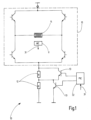
- FIG. 1 a circuit diagram of a control electronics 10 or a section of the control electronics 10 for a motor 100 is shown.
- the control electronics 10 has two essential circuit sections.
- a first circuit section consists of a bridge circuit or an H-bridge, which is integrated into an integrated circuit (IC) 15.
- a second circuit section consists of a series connection of switchable electrical resistors 12, which are switched by means of electronic switching elements 13.
- the resistance network consisting of the series-connected switchable electrical resistors 12 is connected in series to the H-bridge.
- the H-bridge or the IC 15 is always activated at full load or with a maximum predetermined current intensity for controlling the motor 100 according to the invention.
- electrical resistors 12 can be added by means of the electronic switching elements 13 during individual commutation phases in order to increase the effective current of the current pulse 30 through a winding phase 14 of the stator of the motor 100 and thus reduce the rotor speed (T actual ) if this exceeds the predetermined target speed (T target ).
- a slot interruption can be provided for rough adjustment.
- the current pulses 30 are omitted through winding strands 14 during individual commutation phases. If the detected rotor speed (T is ) exceeds the predetermined target speed (T should ), the current pulse 30 can be suspended through a winding phase 14 by means of a rough adjustment, for example in a subsequent commutation phase.
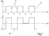
- Figure 2 shows a diagram which shows the output signal 31 of the Hall sensor and the current curve I of the individual current pulses 30 through the winding strands 14.
- the diagram in Figure 2 is based on the example of a rough adjustment.
- the current pulse 30 is interrupted during the commutation phase t4.
- the rotor speed (T ist ) is greater than the predetermined target speed (T target )
- the method provides for the current pulse 30 to be interrupted or omitted during a full revolution of the rotor for as few commutation phases as possible, particularly preferably only during one commutation phase.
- FIG 3 A corresponding diagram is shown, which shows the resulting result of a fine adjustment based on the addition of electrical resistors 12.
- the example shown was the effective current through the winding phases during the commutation phases t4 and t5 reduced by switching on electronic resistors 12 using the electronic switching elements 13. This reduces the rotor speed (T is ) by means of fine adjustment.
- the electrical resistors 12 were not connected or were short-circuited by means of the electronic switching elements 13.
Landscapes
- Engineering & Computer Science (AREA)
- Power Engineering (AREA)
- Control Of Motors That Do Not Use Commutators (AREA)
Claims (9)
- Procédé de commande électrique d'un moteur (100), en particulier d'un moteur de ventilateur, avec plusieurs brins d'enroulement (14), le moteur (100) présentant un moyen (11) pour détecter une vitesse de rotation du rotor (Tist) et/ou une position du rotor d'un rotor du moteur (100), les différents brins d'enroulement (14) étant alimentés en alternance par des impulsions de courant (30) au moyen d'un système électronique de commande (10) du moteur (100), caractérisé en ce que pour l'ajustement grossier de la vitesse de rotation du rotor (Tist) pendant la rotation complète du rotor, aucune impulsion de courant (30) n'est amenée à au moins l'un des brins d'enroulement (14) si la vitesse de rotation du rotor (Tist) détectée est supérieure à la vitesse de rotation de consigne (Tsoll) prédéterminée et si une différence entre la vitesse de rotation du rotor (Tist) détectée et la vitesse de rotation de consigne (Tsoll) prédéterminée dépasse un seuil prédéterminé ; et pour le réglage fin de la vitesse de rotation du rotor (Tist), une résistance électrique commutable (12) est connectée en plus pour au moins une phase de commutation suivante au moyen d'un élément de commutation électronique (13), si la vitesse de rotation du rotor (Tist) détectée est supérieure à la vitesse de rotation de consigne (Tsoll) prédéfinie et si la différence entre la vitesse de rotation du rotor (Tist) détectée et la vitesse de rotation de consigne (Tsoll) prédéfinie est inférieure au seuil prédéfini, la résistance électrique (12) étant montée en série avec le brin d'enroulement (14) de la phase de commutation respective.
- Procédé selon la revendication 1, caractérisé en ce que la vitesse de rotation du rotor (Tist) est détectée en continu et, pour une phase de commutation suivante, l'alimentation en courant de l'un des brins d'enroulement (14) est suspendue si la vitesse de rotation du rotor (Tist) est supérieure à la vitesse de rotation de consigne (Tsoll) prédéfinie.
- Procédé selon la revendication 1 ou 2, caractérisé en ce que pour réduire la vitesse de rotation du rotor (Tist) pendant la rotation complète du rotor, aucune impulsion de courant (30) n'est appliquée à au plus la moitié des brins d'enroulement (14) si la vitesse de rotation du rotor (Tist) détectée est supérieure à la vitesse de rotation de consigne (Tsoll) prédéterminée.
- Procédé selon l'une quelconque des revendications précédentes, caractérisé en ce que pendant une phase de commutation, un état de l'élément de commutation électronique (13) est laissé inchangé.
- Procédé selon l'une quelconque des revendications précédentes, caractérisé en ce qu'une intensité de l'impulsion de courant (30) traversant le brin d'enroulement (14) est réduite pendant la phase de commutation suivante pour réduire la vitesse de rotation du rotor (Tist) au moyen de l'au moins une résistance électrique commutable (12).
- Procédé selon l'une quelconque des revendications précédentes, caractérisé en ce que l'électronique de commande présente plusieurs résistances électriques commutables (12) montées en série, qui sont ajoutées et/ou court-circuitées individuellement au moyen de l'élément de commutation électronique (13) ou au moyen de plusieurs éléments de commutation électroniques (13) en fonction de la différence entre la vitesse de rotation du rotor (Tist) déterminée et la vitesse de rotation de consigne (Tsoll) prédéfinie, et la vitesse de rotation du rotor (Tist) est alors régulée.
- Procédé selon l'une des revendications précédentes, caractérisé en ce que lors du démarrage du moteur (100), pendant au moins une phase de commutation, au moins l'un des brins d'enroulement (14) est alimenté par l'impulsion de courant avec une intensité de courant maximale.
- Moteur (100), en particulier un moteur de ventilateur, avec plusieurs brins d'enroulement (14), le moteur (100) présentant un moyen (11) pour détecter une vitesse de rotation du rotor (Tist) et/ou une position du rotor d'un rotor du moteur (100) et un système électronique de commande (10), caractérisé en ce que les différents brins d'enroulement (14) sont alimentés alternativement par des impulsions de courant (30) au moyen de l'électronique de commande (10) du moteur (100), par un procédé selon l'une des revendications précédentes.
- Ventilateur (200) comprenant un moteur (100) selon la revendication 8.
Applications Claiming Priority (2)
| Application Number | Priority Date | Filing Date | Title |
|---|---|---|---|
| DE102017119740.0A DE102017119740A1 (de) | 2017-08-29 | 2017-08-29 | Ansteuerung eines Lüftermotors für ein verbessertes EMV-Verhalten |
| PCT/EP2018/073021 WO2019042936A1 (fr) | 2017-08-29 | 2018-08-27 | Commande d'un moteur de ventilateur pour un comportement cem amélioré |
Publications (3)
| Publication Number | Publication Date |
|---|---|
| EP3676951A1 EP3676951A1 (fr) | 2020-07-08 |
| EP3676951C0 EP3676951C0 (fr) | 2024-01-10 |
| EP3676951B1 true EP3676951B1 (fr) | 2024-01-10 |
Family
ID=63405227
Family Applications (1)
| Application Number | Title | Priority Date | Filing Date |
|---|---|---|---|
| EP18759945.1A Active EP3676951B1 (fr) | 2017-08-29 | 2018-08-27 | Commande d'un moteur de ventilateur pour l'amélioration de la compatibilité électromagnétique |
Country Status (5)
| Country | Link |
|---|---|
| US (1) | US11539311B2 (fr) |
| EP (1) | EP3676951B1 (fr) |
| CN (1) | CN111034015B (fr) |
| DE (1) | DE102017119740A1 (fr) |
| WO (1) | WO2019042936A1 (fr) |
Families Citing this family (1)
| Publication number | Priority date | Publication date | Assignee | Title |
|---|---|---|---|---|
| EP4012917A1 (fr) * | 2020-12-14 | 2022-06-15 | Robert Bosch GmbH | Procédé de fonctionnement d'un moteur électrique à chaîne unique |
Family Cites Families (23)
| Publication number | Priority date | Publication date | Assignee | Title |
|---|---|---|---|---|
| US3916276A (en) * | 1974-03-28 | 1975-10-28 | Vee Arc Corp | Direct current motor drive |
| JPS58112822A (ja) * | 1981-12-26 | 1983-07-05 | Toyota Central Res & Dev Lab Inc | 自動車用フアンコントロ−ラ |
| US4524316A (en) * | 1983-10-11 | 1985-06-18 | General Electric Company | Speed reducing control system with voltage regulation for a polyphase electric motor |
| JPH06189586A (ja) * | 1992-10-15 | 1994-07-08 | Oki Electric Ind Co Ltd | 冷却ファン制御方法及びそれに用いる回路 |
| KR0158614B1 (ko) * | 1995-11-28 | 1998-12-15 | 김광호 | 모오스-스타트 회로 및 그 제어 방법 |
| US5995710A (en) * | 1998-07-24 | 1999-11-30 | Advanced Motion Controls, Inc. | Speed control for brushless DC motors |
| US6671459B1 (en) * | 2000-06-30 | 2003-12-30 | General Electric Company | DC motor control method and apparatus |
| DE50111285D1 (de) * | 2000-08-30 | 2006-11-30 | Ebm Papst St Georgen Gmbh & Co | Verfahren zum regeln des stromes in einer gleichstrommaschine für einen lüfter |
| DE10322118A1 (de) * | 2003-05-09 | 2004-12-16 | Visteon Global Technologies, Inc., Dearborn | Drehzahlregelung eines Gleichstrommotors |
| DE10336945A1 (de) * | 2003-08-07 | 2005-02-24 | Robert Bosch Gmbh | Verfahren und Vorrichtung zum Abbremsen eines elektrischen Gebläsemotors |
| DE10339095B4 (de) * | 2003-08-22 | 2006-05-04 | Elektra Gmbh | Steuerschaltung für einen geschalteten Reluktanzmotor |
| US7012392B2 (en) | 2004-02-06 | 2006-03-14 | Honeywell International Inc. | Multi-stage dynamic braking resistor network |
| WO2007140927A1 (fr) | 2006-06-03 | 2007-12-13 | Ebm-Papst St. Georgen Gmbh & Co. Kg | Procédé de fonctionnement d'un moteur à commutation électronique et moteur pour mettre en œuvre ledit procédé |
| US7279862B1 (en) | 2006-08-04 | 2007-10-09 | Gm Global Technology Operations, Inc. | Fault handling of inverter driven PM motor drives |
| US20080272720A1 (en) * | 2007-05-03 | 2008-11-06 | Atmel Corporation | Accurate motor speed control |
| CN101589545B (zh) * | 2007-12-26 | 2013-01-16 | 三洋电机株式会社 | 马达驱动电路、风扇马达、电子设备、以及笔记本型个人计算机 |
| DE102011116799A1 (de) * | 2011-10-24 | 2013-04-25 | Ebm-Papst St. Georgen Gmbh & Co. Kg | Lüfter |
| DE102013220727A1 (de) * | 2013-10-14 | 2015-04-16 | Schmidhauser Ag | Steuergerät |
| JP6236341B2 (ja) * | 2014-03-25 | 2017-11-22 | アスモ株式会社 | モータ駆動装置 |
| JP6322134B2 (ja) * | 2014-12-26 | 2018-05-09 | ミネベアミツミ株式会社 | モータ制御装置およびモータ制御方法 |
| CN106301134A (zh) * | 2015-06-08 | 2017-01-04 | 华帝股份有限公司 | 一种可控硅调速吸油烟机的控制方法及控制装置 |
| DE102015012540B4 (de) * | 2015-09-24 | 2025-05-28 | Audi Ag | Verfahren zum Betreiben eines Lenksystems |
| JP6555186B2 (ja) * | 2016-05-10 | 2019-08-07 | 株式会社デンソー | 交流電動機の制御装置 |
-
2017
- 2017-08-29 DE DE102017119740.0A patent/DE102017119740A1/de active Pending
-
2018
- 2018-08-27 EP EP18759945.1A patent/EP3676951B1/fr active Active
- 2018-08-27 WO PCT/EP2018/073021 patent/WO2019042936A1/fr not_active Ceased
- 2018-08-27 US US16/642,229 patent/US11539311B2/en active Active
- 2018-08-27 CN CN201880055940.7A patent/CN111034015B/zh active Active
Also Published As
| Publication number | Publication date |
|---|---|
| EP3676951C0 (fr) | 2024-01-10 |
| US11539311B2 (en) | 2022-12-27 |
| CN111034015B (zh) | 2024-04-02 |
| CN111034015A (zh) | 2020-04-17 |
| EP3676951A1 (fr) | 2020-07-08 |
| WO2019042936A1 (fr) | 2019-03-07 |
| DE102017119740A1 (de) | 2019-02-28 |
| US20200358377A1 (en) | 2020-11-12 |
Similar Documents
| Publication | Publication Date | Title |
|---|---|---|
| EP1413044B1 (fr) | Procede pour faire fonctionner un moteur a commutation electronique et moteur pour la mise en oeuvre dudit procede | |
| DE102015203960B4 (de) | Fail-safe-Vorrichtung für einen Umrichter | |
| DE4009184C2 (fr) | ||
| EP2807049B1 (fr) | Dispositif de protection contre les surtensions pour un entraînement électrique | |
| EP0989666B9 (fr) | Système de commande de vitesse de moteurs AC | |
| WO2008122602A1 (fr) | Protection contre la surtension pour un convertisseur | |
| DE102007040560A1 (de) | Verfahren zur Ansteuerung eines Umrichters sowie zugehörige Vorrichtung | |
| DE102008037543A1 (de) | Motorsteuervorrichtung, Fahrzeuglüfter-Ansteuervorrichtung und Motorsteuerverfahren | |
| WO2013156571A2 (fr) | Commande destinée à un moteur à courant continu sans balai | |
| WO2017125207A1 (fr) | Procédé pour réguler la tension de circuit intermédiaire d'un véhicule hybride ou électrique après déconnexion de la batterie haute tension | |
| EP0935336B2 (fr) | Méthode et dispositif de commande d' un moteur synchron | |
| DE102012208458A1 (de) | Verfahren zum Betreiben eines Stromrichters und Stromrichtersteuereinheit | |
| EP3285381A1 (fr) | Procédé de fonctionnement d'une machine électrique et machine électrique | |
| DE10146523A1 (de) | Antriebssteuereinrichtung für einen stromrichtergespeisten, mehrphasigen Motor | |
| EP2583379B1 (fr) | Procédé et dispositif pour adapter une plage de vitesses de rotation d'un moteur électrique | |
| EP2633616B1 (fr) | Procédé permettant de réduire une ondulation de tension due à une irrégularité de rotation sur un générateur entraîné par un moteur à combustion interne | |
| WO2019042936A1 (fr) | Commande d'un moteur de ventilateur pour un comportement cem amélioré | |
| DE102012012762B4 (de) | Einrichtung zur Bestimmung von Positionen eines Rotors in elektrischen Maschinen | |
| DE4413802C2 (de) | Verfahren und Vorrichtung zum Steuern der Drehzahl eines elektrischen Dreiphasen-Asynchronmotors | |
| DE102020215370B4 (de) | Fahrzeugbetrieb-Inverter, Fahrzeugantrieb und Verfahren zum Betreiben eines Fahrzeugantrieb-Inverters | |
| EP1533892B1 (fr) | Méthode pour réduire le temps de freinage d'un moteur | |
| DE2132380A1 (de) | Einrichtung zum schutz gegen ueberspannungen | |
| DE102017130869A1 (de) | Elektrisches Getriebe und Verfahren zum Betreiben eines Elektromotors | |
| DE102017213463A1 (de) | Motorantriebssystem und motorbetriebswiederaufnahme-verfahren | |
| WO2016012301A1 (fr) | Procédé de commande d'au moins une machine électrique pouvant fonctionner en générateur et moyen pour mettre en œuvre celui-ci |
Legal Events
| Date | Code | Title | Description |
|---|---|---|---|
| STAA | Information on the status of an ep patent application or granted ep patent |
Free format text: STATUS: UNKNOWN |
|
| STAA | Information on the status of an ep patent application or granted ep patent |
Free format text: STATUS: THE INTERNATIONAL PUBLICATION HAS BEEN MADE |
|
| PUAI | Public reference made under article 153(3) epc to a published international application that has entered the european phase |
Free format text: ORIGINAL CODE: 0009012 |
|
| STAA | Information on the status of an ep patent application or granted ep patent |
Free format text: STATUS: REQUEST FOR EXAMINATION WAS MADE |
|
| 17P | Request for examination filed |
Effective date: 20200325 |
|
| AK | Designated contracting states |
Kind code of ref document: A1 Designated state(s): AL AT BE BG CH CY CZ DE DK EE ES FI FR GB GR HR HU IE IS IT LI LT LU LV MC MK MT NL NO PL PT RO RS SE SI SK SM TR |
|
| AX | Request for extension of the european patent |
Extension state: BA ME |
|
| DAV | Request for validation of the european patent (deleted) | ||
| DAX | Request for extension of the european patent (deleted) | ||
| STAA | Information on the status of an ep patent application or granted ep patent |
Free format text: STATUS: EXAMINATION IS IN PROGRESS |
|
| 17Q | First examination report despatched |
Effective date: 20211220 |
|
| P01 | Opt-out of the competence of the unified patent court (upc) registered |
Effective date: 20230529 |
|
| REG | Reference to a national code |
Ref country code: DE Ref legal event code: R079 Free format text: PREVIOUS MAIN CLASS: H02P0007290000 Ipc: H02P0006260000 Ref document number: 502018013957 Country of ref document: DE |
|
| RIC1 | Information provided on ipc code assigned before grant |
Ipc: H02P 3/12 20060101ALI20230816BHEP Ipc: H02P 3/08 20060101ALI20230816BHEP Ipc: H02P 7/29 20160101ALI20230816BHEP Ipc: H02P 29/50 20160101ALI20230816BHEP Ipc: H02P 6/26 20160101AFI20230816BHEP |
|
| GRAP | Despatch of communication of intention to grant a patent |
Free format text: ORIGINAL CODE: EPIDOSNIGR1 |
|
| STAA | Information on the status of an ep patent application or granted ep patent |
Free format text: STATUS: GRANT OF PATENT IS INTENDED |
|
| INTG | Intention to grant announced |
Effective date: 20230926 |
|
| GRAS | Grant fee paid |
Free format text: ORIGINAL CODE: EPIDOSNIGR3 |
|
| GRAA | (expected) grant |
Free format text: ORIGINAL CODE: 0009210 |
|
| STAA | Information on the status of an ep patent application or granted ep patent |
Free format text: STATUS: THE PATENT HAS BEEN GRANTED |
|
| AK | Designated contracting states |
Kind code of ref document: B1 Designated state(s): AL AT BE BG CH CY CZ DE DK EE ES FI FR GB GR HR HU IE IS IT LI LT LU LV MC MK MT NL NO PL PT RO RS SE SI SK SM TR |
|
| REG | Reference to a national code |
Ref country code: GB Ref legal event code: FG4D Free format text: NOT ENGLISH |
|
| REG | Reference to a national code |
Ref country code: CH Ref legal event code: EP |
|
| REG | Reference to a national code |
Ref country code: DE Ref legal event code: R096 Ref document number: 502018013957 Country of ref document: DE |
|
| REG | Reference to a national code |
Ref country code: IE Ref legal event code: FG4D Free format text: LANGUAGE OF EP DOCUMENT: GERMAN |
|
| U01 | Request for unitary effect filed |
Effective date: 20240110 |
|
| U07 | Unitary effect registered |
Designated state(s): AT BE BG DE DK EE FI FR IT LT LU LV MT NL PT SE SI Effective date: 20240115 |
|
| P04 | Withdrawal of opt-out of the competence of the unified patent court (upc) registered |
Effective date: 20240110 |
|
| PG25 | Lapsed in a contracting state [announced via postgrant information from national office to epo] |
Ref country code: IS Free format text: LAPSE BECAUSE OF FAILURE TO SUBMIT A TRANSLATION OF THE DESCRIPTION OR TO PAY THE FEE WITHIN THE PRESCRIBED TIME-LIMIT Effective date: 20240510 |
|
| PG25 | Lapsed in a contracting state [announced via postgrant information from national office to epo] |
Ref country code: GR Free format text: LAPSE BECAUSE OF FAILURE TO SUBMIT A TRANSLATION OF THE DESCRIPTION OR TO PAY THE FEE WITHIN THE PRESCRIBED TIME-LIMIT Effective date: 20240411 |
|
| PG25 | Lapsed in a contracting state [announced via postgrant information from national office to epo] |
Ref country code: RS Free format text: LAPSE BECAUSE OF FAILURE TO SUBMIT A TRANSLATION OF THE DESCRIPTION OR TO PAY THE FEE WITHIN THE PRESCRIBED TIME-LIMIT Effective date: 20240410 Ref country code: HR Free format text: LAPSE BECAUSE OF FAILURE TO SUBMIT A TRANSLATION OF THE DESCRIPTION OR TO PAY THE FEE WITHIN THE PRESCRIBED TIME-LIMIT Effective date: 20240110 |
|
| PG25 | Lapsed in a contracting state [announced via postgrant information from national office to epo] |
Ref country code: ES Free format text: LAPSE BECAUSE OF FAILURE TO SUBMIT A TRANSLATION OF THE DESCRIPTION OR TO PAY THE FEE WITHIN THE PRESCRIBED TIME-LIMIT Effective date: 20240110 |
|
| PG25 | Lapsed in a contracting state [announced via postgrant information from national office to epo] |
Ref country code: RS Free format text: LAPSE BECAUSE OF FAILURE TO SUBMIT A TRANSLATION OF THE DESCRIPTION OR TO PAY THE FEE WITHIN THE PRESCRIBED TIME-LIMIT Effective date: 20240410 Ref country code: NO Free format text: LAPSE BECAUSE OF FAILURE TO SUBMIT A TRANSLATION OF THE DESCRIPTION OR TO PAY THE FEE WITHIN THE PRESCRIBED TIME-LIMIT Effective date: 20240410 Ref country code: IS Free format text: LAPSE BECAUSE OF FAILURE TO SUBMIT A TRANSLATION OF THE DESCRIPTION OR TO PAY THE FEE WITHIN THE PRESCRIBED TIME-LIMIT Effective date: 20240510 Ref country code: HR Free format text: LAPSE BECAUSE OF FAILURE TO SUBMIT A TRANSLATION OF THE DESCRIPTION OR TO PAY THE FEE WITHIN THE PRESCRIBED TIME-LIMIT Effective date: 20240110 Ref country code: GR Free format text: LAPSE BECAUSE OF FAILURE TO SUBMIT A TRANSLATION OF THE DESCRIPTION OR TO PAY THE FEE WITHIN THE PRESCRIBED TIME-LIMIT Effective date: 20240411 Ref country code: ES Free format text: LAPSE BECAUSE OF FAILURE TO SUBMIT A TRANSLATION OF THE DESCRIPTION OR TO PAY THE FEE WITHIN THE PRESCRIBED TIME-LIMIT Effective date: 20240110 |
|
| PG25 | Lapsed in a contracting state [announced via postgrant information from national office to epo] |
Ref country code: PL Free format text: LAPSE BECAUSE OF FAILURE TO SUBMIT A TRANSLATION OF THE DESCRIPTION OR TO PAY THE FEE WITHIN THE PRESCRIBED TIME-LIMIT Effective date: 20240110 |
|
| PG25 | Lapsed in a contracting state [announced via postgrant information from national office to epo] |
Ref country code: PL Free format text: LAPSE BECAUSE OF FAILURE TO SUBMIT A TRANSLATION OF THE DESCRIPTION OR TO PAY THE FEE WITHIN THE PRESCRIBED TIME-LIMIT Effective date: 20240110 |
|
| U20 | Renewal fee for the european patent with unitary effect paid |
Year of fee payment: 7 Effective date: 20240826 |
|
| REG | Reference to a national code |
Ref country code: DE Ref legal event code: R097 Ref document number: 502018013957 Country of ref document: DE |
|
| PG25 | Lapsed in a contracting state [announced via postgrant information from national office to epo] |
Ref country code: SM Free format text: LAPSE BECAUSE OF FAILURE TO SUBMIT A TRANSLATION OF THE DESCRIPTION OR TO PAY THE FEE WITHIN THE PRESCRIBED TIME-LIMIT Effective date: 20240110 |
|
| PG25 | Lapsed in a contracting state [announced via postgrant information from national office to epo] |
Ref country code: CZ Free format text: LAPSE BECAUSE OF FAILURE TO SUBMIT A TRANSLATION OF THE DESCRIPTION OR TO PAY THE FEE WITHIN THE PRESCRIBED TIME-LIMIT Effective date: 20240110 |
|
| PG25 | Lapsed in a contracting state [announced via postgrant information from national office to epo] |
Ref country code: SK Free format text: LAPSE BECAUSE OF FAILURE TO SUBMIT A TRANSLATION OF THE DESCRIPTION OR TO PAY THE FEE WITHIN THE PRESCRIBED TIME-LIMIT Effective date: 20240110 |
|
| PG25 | Lapsed in a contracting state [announced via postgrant information from national office to epo] |
Ref country code: SM Free format text: LAPSE BECAUSE OF FAILURE TO SUBMIT A TRANSLATION OF THE DESCRIPTION OR TO PAY THE FEE WITHIN THE PRESCRIBED TIME-LIMIT Effective date: 20240110 Ref country code: SK Free format text: LAPSE BECAUSE OF FAILURE TO SUBMIT A TRANSLATION OF THE DESCRIPTION OR TO PAY THE FEE WITHIN THE PRESCRIBED TIME-LIMIT Effective date: 20240110 Ref country code: RO Free format text: LAPSE BECAUSE OF FAILURE TO SUBMIT A TRANSLATION OF THE DESCRIPTION OR TO PAY THE FEE WITHIN THE PRESCRIBED TIME-LIMIT Effective date: 20240110 Ref country code: CZ Free format text: LAPSE BECAUSE OF FAILURE TO SUBMIT A TRANSLATION OF THE DESCRIPTION OR TO PAY THE FEE WITHIN THE PRESCRIBED TIME-LIMIT Effective date: 20240110 |
|
| PLBE | No opposition filed within time limit |
Free format text: ORIGINAL CODE: 0009261 |
|
| STAA | Information on the status of an ep patent application or granted ep patent |
Free format text: STATUS: NO OPPOSITION FILED WITHIN TIME LIMIT |
|
| 26N | No opposition filed |
Effective date: 20241011 |
|
| P05 | Withdrawal of opt-out of the competence of the unified patent court (upc) changed |
Free format text: CASE NUMBER: APP_1432/2024 Effective date: 20240115 |
|
| REG | Reference to a national code |
Ref country code: CH Ref legal event code: PL |
|
| GBPC | Gb: european patent ceased through non-payment of renewal fee |
Effective date: 20240827 |
|
| PG25 | Lapsed in a contracting state [announced via postgrant information from national office to epo] |
Ref country code: CH Free format text: LAPSE BECAUSE OF NON-PAYMENT OF DUE FEES Effective date: 20240831 Ref country code: MC Free format text: LAPSE BECAUSE OF FAILURE TO SUBMIT A TRANSLATION OF THE DESCRIPTION OR TO PAY THE FEE WITHIN THE PRESCRIBED TIME-LIMIT Effective date: 20240110 |
|
| PG25 | Lapsed in a contracting state [announced via postgrant information from national office to epo] |
Ref country code: GB Free format text: LAPSE BECAUSE OF NON-PAYMENT OF DUE FEES Effective date: 20240827 |
|
| PG25 | Lapsed in a contracting state [announced via postgrant information from national office to epo] |
Ref country code: IE Free format text: LAPSE BECAUSE OF NON-PAYMENT OF DUE FEES Effective date: 20240827 |
|
| U20 | Renewal fee for the european patent with unitary effect paid |
Year of fee payment: 8 Effective date: 20250807 |
|
| PG25 | Lapsed in a contracting state [announced via postgrant information from national office to epo] |
Ref country code: CY Free format text: LAPSE BECAUSE OF FAILURE TO SUBMIT A TRANSLATION OF THE DESCRIPTION OR TO PAY THE FEE WITHIN THE PRESCRIBED TIME-LIMIT; INVALID AB INITIO Effective date: 20180827 |
|
| PG25 | Lapsed in a contracting state [announced via postgrant information from national office to epo] |
Ref country code: HU Free format text: LAPSE BECAUSE OF FAILURE TO SUBMIT A TRANSLATION OF THE DESCRIPTION OR TO PAY THE FEE WITHIN THE PRESCRIBED TIME-LIMIT; INVALID AB INITIO Effective date: 20180827 |