EP3677020B1 - Verfahren zur bilderfassung durch einen bildsensor vom cmos-typ zur erkennung eines optisch lesbaren codes - Google Patents
Verfahren zur bilderfassung durch einen bildsensor vom cmos-typ zur erkennung eines optisch lesbaren codes Download PDFInfo
- Publication number
- EP3677020B1 EP3677020B1 EP18755846.5A EP18755846A EP3677020B1 EP 3677020 B1 EP3677020 B1 EP 3677020B1 EP 18755846 A EP18755846 A EP 18755846A EP 3677020 B1 EP3677020 B1 EP 3677020B1
- Authority
- EP
- European Patent Office
- Prior art keywords
- exposure
- pixels
- image
- phase
- values
- Prior art date
- Legal status (The legal status is an assumption and is not a legal conclusion. Google has not performed a legal analysis and makes no representation as to the accuracy of the status listed.)
- Active
Links
Images


Classifications
-
- G—PHYSICS
- G06—COMPUTING OR CALCULATING; COUNTING
- G06K—GRAPHICAL DATA READING; PRESENTATION OF DATA; RECORD CARRIERS; HANDLING RECORD CARRIERS
- G06K7/00—Methods or arrangements for sensing record carriers, e.g. for reading patterns
- G06K7/10—Methods or arrangements for sensing record carriers, e.g. for reading patterns by electromagnetic radiation, e.g. optical sensing; by corpuscular radiation
- G06K7/10544—Methods or arrangements for sensing record carriers, e.g. for reading patterns by electromagnetic radiation, e.g. optical sensing; by corpuscular radiation by scanning of the records by radiation in the optical part of the electromagnetic spectrum
- G06K7/10712—Fixed beam scanning
- G06K7/10722—Photodetector array or CCD scanning
- G06K7/10752—Exposure time control
-
- G—PHYSICS
- G06—COMPUTING OR CALCULATING; COUNTING
- G06K—GRAPHICAL DATA READING; PRESENTATION OF DATA; RECORD CARRIERS; HANDLING RECORD CARRIERS
- G06K7/00—Methods or arrangements for sensing record carriers, e.g. for reading patterns
- G06K7/10—Methods or arrangements for sensing record carriers, e.g. for reading patterns by electromagnetic radiation, e.g. optical sensing; by corpuscular radiation
- G06K7/10544—Methods or arrangements for sensing record carriers, e.g. for reading patterns by electromagnetic radiation, e.g. optical sensing; by corpuscular radiation by scanning of the records by radiation in the optical part of the electromagnetic spectrum
- G06K7/10554—Moving beam scanning
- G06K7/10564—Light sources
-
- G—PHYSICS
- G06—COMPUTING OR CALCULATING; COUNTING
- G06K—GRAPHICAL DATA READING; PRESENTATION OF DATA; RECORD CARRIERS; HANDLING RECORD CARRIERS
- G06K7/00—Methods or arrangements for sensing record carriers, e.g. for reading patterns
- G06K7/10—Methods or arrangements for sensing record carriers, e.g. for reading patterns by electromagnetic radiation, e.g. optical sensing; by corpuscular radiation
- G06K7/10544—Methods or arrangements for sensing record carriers, e.g. for reading patterns by electromagnetic radiation, e.g. optical sensing; by corpuscular radiation by scanning of the records by radiation in the optical part of the electromagnetic spectrum
- G06K7/10821—Methods or arrangements for sensing record carriers, e.g. for reading patterns by electromagnetic radiation, e.g. optical sensing; by corpuscular radiation by scanning of the records by radiation in the optical part of the electromagnetic spectrum further details of bar or optical code scanning devices
- G06K7/10851—Circuits for pulse shaping, amplifying, eliminating noise signals, checking the function of the sensing device
-
- H—ELECTRICITY
- H04—ELECTRIC COMMUNICATION TECHNIQUE
- H04N—PICTORIAL COMMUNICATION, e.g. TELEVISION
- H04N23/00—Cameras or camera modules comprising electronic image sensors; Control thereof
- H04N23/70—Circuitry for compensating brightness variation in the scene
- H04N23/73—Circuitry for compensating brightness variation in the scene by influencing the exposure time
-
- H—ELECTRICITY
- H04—ELECTRIC COMMUNICATION TECHNIQUE
- H04N—PICTORIAL COMMUNICATION, e.g. TELEVISION
- H04N25/00—Circuitry of solid-state image sensors [SSIS]; Control thereof
- H04N25/50—Control of the SSIS exposure
- H04N25/53—Control of the integration time
- H04N25/533—Control of the integration time by using differing integration times for different sensor regions
Definitions
- the present invention relates to a method for controlling image capture by a CMOS type sensor, with active pixels (pixel structure with photosensitive element and control transistors) for the recognition of optically readable code.
- CMOS type sensor with active pixels (pixel structure with photosensitive element and control transistors) for the recognition of optically readable code.
- These sensors are integrated into electro-optical code recognition devices, generally called bar code readers.
- bar code readers These readers are commonly used in many industrial and commercial sectors, as means of automated data collection, replacing keyboard input, for applications as varied as sales, traceability (manufacturing, distribution), shipping of goods, health care, inventory management, book lending ...
- codes generally printed (label) or engraved on the surface of an object, follow a generally bichromatic symbology which can be monodimensional and linear (bar code) or multidimensional (QR code, PDF 417, Data Matrix, etc.).
- Each symbol or pattern uniquely represents an information value (or a set of values) that is associated with the object to which the code is affixed, such as a price and / or a discount, traceability data ( date, place of manufacture, dispatch, collection, etc.), etc.
- Decoding the code makes it possible to reliably obtain the information value (s) associated with the object concerned.
- a CMOS type matrix image sensor code reader comprises a lighting device comprising a light source (LEDs and / or laser for example) associated with an optical assembly (mirrors, lenses) provided to illuminate the target code to be acquired .
- the sensor takes an image of this target code and transmits the image data obtained to an external digital processing system (connected to the reader by any means of communication, wired or wireless) and it is this system external to the sensor which performs code decoding.
- the senor provides a good image of the code as quickly as possible. quality, that is to say of sufficient quality to allow decoding or recognition without error. More precisely, the image supplied by the sensor must be well positioned in the useful dynamic range of the sensor, that is to say not too underexposed, otherwise the signal-to-noise ratio will be too low; nor too overexposed, so as not to lose too much useful information.
- the quality of the image obtained depends on the shooting parameters of the sensor, and in particular on the exposure time of the pixels.
- the exposure time is generally preset in the factory or on site by an operator, to a value which is defined according to the operational conditions of use: light environment (use outdoors, indoors, under artificial light); power of the light source of the reader, which illuminates the object / code; type of material of the objects bearing the codes; reader fixed or held manually.
- this preset "default" value does not in practice make it possible to obtain a good quality image from the first image capture, because there are too many external factors linked to the ergonomics of the reader which prevent a complete mastery of the images. actual shooting conditions.
- the ergonomics of the reader define how it will be used.
- the reader can be fixed, and the target code is brought manually or mechanically in front of the reader; or else the reader is portable, that is to say handled (by hand) or carried (on the arm, on the head, etc.) by an operator.
- the environment in which the reader operates can be with natural or artificial ambient lighting.
- the object itself (more or less reflective character of the surface presenting the code) or the way in which it is presented (distance, angle of presentation) are all factors which can also influence the quantity of light that the sensor.
- shooting parameters which will not necessarily be adapted to the conditions of the shooting of the target code, at the time of the trigger.
- an iterative image-taking loop driven by the external code recognition system is used with the aim of adapting the shooting parameters and especially the exposure time of the pixels, to real conditions.
- This loop takes place as follows: after triggering, the sensor begins to acquire images of the target code, periodically, which it transmits to the external system. For each take image, it applies the current values of the parameters supplied by the capture register of the sensor, which in particular defines the value of the exposure time. For its part, the system receives the images, and for each image received, if it judges its quality to be unsatisfactory to allow decoding of the code, i.e.
- the external system determines and transmits a new exposure time value, which is stored in the sensor's shooting parameters register in order to obtain a new image, which should be better exposed. This value will only be taken into account by the sensor for the next image capture. This iterative acquisition and delivery loop lasts until the system validates the image quality and successfully decodes the code.
- the determination of a new exposure time value by the external system uses one or more algorithms which exploit the histogram of the image, that is to say the distribution of the pixels by gray levels of the image (or the probability density, if the histogram is normalized). If we have 256 gray levels coded in the image, the histogram indicates how many pixels have the value 0, 1, up to 255.
- the external system therefore calculates the histogram of the image received; based on the current value of the exposure time, and on the gain of the pixel reading chain (but this gain is generally fixed at 1 for this type of application), which are values supplied by the sensor with the image data, it determines where appropriate a new exposure time value by comparing one or more characteristic values of the histogram (mean value, percentage of pixels having a value less than a given gray level, percentage of saturated pixels, etc.) obtained, at reference values. The new exposure time value thus determined will be lower than the current value, if the image was overexposed, and on the contrary greater if the image was underexposed.
- the time for determining and writing in the sensor a new exposure time value, the new exposure time value imposed by the external system from data of a first image supplied by the sensor will only be effectively applied at best for the third or even the fourth image capture which follows the first image capture; the system must still check the quality of this third or fourth image, and only then, if this quality is good, carry out the decoding of the code.
- This loop of external, iterative determination of an exposure time suitable for the acquisition of the current target code induces a response time of the code reader which is not negligible, corresponding to the reception time of at least three or four. images.
- the response time of the reader is too slow, between the moment it is triggered and decoding. This perceptible slowness degrades the ergonomics of the reader for the operator and the consumption of the system increases with the number of images which are taken: consumption of the sensor, and also of the light source (number of flashes of the LEDs) .
- the patent application EP 1 791 074 proposes to determine an optimal exposure time for barcode image capture, by varying the exposure time from one matrix area covering a set of rows to another, in an exposure mode context slippery (rolling).
- We have a first so-called search Image applying in "rolling" mode, 5 different exposure times on 5 image areas, and statistical calculations in each search image area are made to discriminate the areas. and determine the best exposure time, or extrapolate from the two best exposure times.
- the exposure time thus determined is then used for a new image capture, which is the image outputted.
- the method has the drawback of requiring two complete image captures, and of comparing statistics which are calculated on different image zones.
- the invention provides another technique for determining the optimum exposure time for taking a target code image by a CMOS sensor code reader, which improves both response time and image quality. supplied as output.
- the technical solution at the basis of the present invention is a method of image acquisition of a target code which allows the sensor, after triggering of the reader for the acquisition of the target code, to determine quickly and internally ("on-chip"), a desirable value of exposure time for the image capture of this code by means of a measurement mode prior to the nominal image capture, which performs a rapid acquisition of image data for at least two different values of exposure time distributed periodically according to the rows or according to the columns of the matrix, and the image data obtained for these different exposure time values are only used for the sensor and only to quickly define the desirable exposure time value.
- This value is then used to perform a nominal image capture, and the image obtained is that delivered at the output, for code decoding / recognition.
- the response time of the code reader using such a sensor is significantly reduced.
- the fast image data acquisition time for determining the desirable time value, added to the acquisition and output time, of a single nominal image.
- the different exposure time values being distributed periodically, according to the rows or else according to the columns, the determination of the nominal exposure time is established on the basis of statistics calculated on data from pixels distributed regularly. on the whole image. That is to say that these data of the measurement image have a good spatial homogeneity (sub-sampling) and a good temporal homogeneity (Ti) favorable to an optimal determination of the desirable exposure time.
- This double spatial and temporal homogeneity is favored by choosing a distribution of the different exposure times in combination with a subsampling as a function of the rows, in the phase of rapid reading of the measurement image.
- the method of the invention therefore makes it possible to perceptibly improve the ergonomics of the code reader and to reduce its consumption.
- the k exposure time values are distributed in a periodic pattern over the columns of the matrix.
- the subsampling of the rows is in a ratio of 1 to 8, 16 or 32.
- the histograms for the different exposure time values of the measurement mode are calculated on a number of gray levels less than the number of gray levels corresponding to the resolution of the analog-to-digital conversion means. in measurement mode.
- the invention relates to code readers with CMOS sensors, both those which are fixed, such as those integrated into automatic checkouts in supermarkets, and those which are portable and operated by an operator.
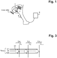
- a code reader, portable in the example, is illustrated on the figure 1 . It comprises an electronic sensor of CMOS type 1, with an active pixel matrix, a light source 2 for illuminating the target (the code affixed to an object) through a scanning window o; an optical system 3 designed to return the light reflected by the target onto the matrix of pixels of the sensor.
- the light source generally uses LEDs to illuminate the target for image capture, by flash.
- Certain systems can also integrate a laser source associated with diffractive optics, in order to help the operator center the target code prior to taking an image, by projecting a particular pattern (crosses, angles, etc. .etc.). This operation is known by the Anglo-Saxon term "to love". This laser source is normally off, before the LEDs flash for the image capture.
- the portable reader is provided with a trigger 4 or an equivalent mechanism, manual or otherwise, for triggering the reader.
- a trigger signal triggers the reader from a low power sleep mode, the light source is activated and the sensor as well, to acquire and provide an image of the target code to an external processing system. digital data which decodes the code.
- the image is supplied to the processing system 5 under form of a data stream (digital) by a transmission cable, for example a USB cable, or by a wireless transmission medium.
- the trigger trigger signal is for example generated by a presence detection system integrated into the reader.
- the CMOS sensor conventionally comprises, as shown in figure 2 , a matrix M of n rows Row 0 to Row n-1 and m columns Col 0 to Col m-1 of active pixels (n, m integers), a read circuit ADC with analog-to-digital converter (s), a COMP circuit digital processing capable of performing calculations on the image data supplied by the read circuit and in particular calculating a histogram and an interface I / O circuit for supplying the image data to the external system 5.
- SEQ sensor sequencing circuit
- the sequencing circuit supplies the control signals for the transistors of the active pixels.
- an active pixel structure can include transistors other than the four transistors above, depending on whether a node is provided. temporary storage, separate from the read node, or a gain stage, etc. Also some transistors can be shared between several pixels.
- the electronic control of the exposure time of the active pixels is used more especially, via the initialization and transfer transistors (gates), to implement, in and by the sensor, a measurement mode making it possible to determine a desirable value of exposure time Topt for acquiring an image of a target code, prior to a nominal image capture of the target code carried out in the usual way, but with the value Topt.
- the measurement mode therefore uses the possibilities of adjusting the exposure time of an active pixel, to apply different exposure time values to the pixels. This can be achieved by adjusting the (gate) control of the initialization transistor which sets the start of the exposure time and / or the (gate) control of the transfer transistor on the associated storage node (which may or may not be the read node) which sets the end, taking into account the capture mode (s) implemented in the sensor and the topology of the control lines.
- a Cmos sensor can offer one or two capture modes, global or offset. In the global image capture mode, called “global shutter” or “snapshot”, all the pixels integrate at the same time: the exposure phase begins at the same time for all the pixels and it ends at the same time for all pixels as well.
- the reading phase row after row, then begins.
- This global capture mode is preferred for high performance applications (eg speed) because it allows to freeze the image and to avoid the distortions inherent in the shifted mode which can degrade the image quality in particular if the object moves.
- the shifted (or sliding) capture mode called "rolling shutter”
- the rows integrate successively in a shifted manner: the start of the exposure phase is defined for each row of pixels and shifted from one row to the next and the exposure time in a row of pixels does not start until the reading of the previous row of pixels is complete.
- the global capture mode is preferred for high performance applications (eg speed) because it allows to freeze the image and to avoid the distortions inherent in the offset capture mode which can degrade the image quality in particular if the object moves.
- the topology of the control lines responds to various constraints such as: number of transistors, pixels with shared or not shared transistors, overall and / or offset capture mode; optimization of the pixel opening rate.
- the command line topology presented in figure 2 which allows control of the end of exposure time per column is suitable for a global capture mode; while the topology presented in figure 3 which allows control of the start and end of exposure time per row allows both types of capture.
- the sequencing circuit SEQ makes it possible to generate the control signals of the pixels and of the other circuits of the sensor (converters, output interface, etc.) with ad hoc pixel timing for the capture mode (s) and the topology implemented.
- the sequencing circuit SEQ makes it possible to generate the control signals of the pixels and of the other circuits of the sensor (converters, output interface, etc.) with ad hoc pixel timing for the capture mode (s) and the topology implemented.
- This method triggered by the activation of the Trig signal, allows the supply by the sensor 1 of a single image of nominal quality directly exploitable by the processing system 5 for decoding / recognition of the code, since it was obtained by applying to the pixel matrix an exposure time value, for the integration of light, which has been determined internally by the sensor itself ( "on-chip” ) , in a measuring mode activated before the d mode nominal acquisition, on the basis of histograms calculated from at least one measurement image of degraded quality and for at least two different exposure time values.
- degraded quality means that the number of pixels of the measurement image is less than the number of pixels of the image of nominal quality: in other words, the pixel matrix is downsampled; and / or that the resolution of the measurement (reading) of the quantity of light integrated by a pixel is lower in the measurement mode than that of the acquisition mode nominal: in other words, the analog-to-digital conversion of the light levels read on the pixels provides a result which is encoded on fewer gray levels in the measurement mode than in the nominal acquisition mode. For example, if in the conversion for the nominal image is carried out on 10 or 12 bits, for the measurement image, the conversion is preferably carried out on 8 bits, or even on 4 bits.
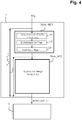
- the figure 4 presents a general flowchart of a method for acquiring a target code according to a first implementation of the invention, with a Mode_MES measurement mode triggered by the signal Trig which provides for a single measurement image capture for which each pixel is associated with an exposure time value from among k different exposure time values T1 to Tk, k integer at least equal to two.
- the measurement mode mainly comprises three phases controlled by the sequencing circuit of the sensor: a phase 100 for the rapid acquisition of image data DATA (Ti) for each of the k exposure time values; then a phase 110 of determination by the digital processing circuit COMP of the sensor from the image data DATA (Ti), of a desirable exposure time value Topt for taking an image of the target code concerned: ni too large, so as not to have too many saturated pixels, nor too weak, so as not to lose a signal (black pixels), according to image quality criteria established for efficient decoding of the code; and a phase 120 of storing the value Topt in the corresponding field Tr of the recording parameters register REG of the sensor.
- the method then activates the nominal acquisition mode Mode_ACQ, which uses the current values of the parameters of the register REG, in particular the parameter Tr.
- This register can set other parameters such as a value G of conversion gain, but in the applications of code reader for which one does not seek to reconstruct an image with precision, but to decode a code, this gain is generally fixed at 1.
- An image of optimal quality (for code decoding) is obtained: the image data corresponding Data-OUT values obtained with the exposure time value Tr are read from the pixels of the matrix (complete image) and transmitted to the external processing system 5.
- the values of the parameters of the register REG (Tr, G) are also supplied with these data, to which can also be added the data of the histogram H (Tr) calculated by the digital processing circuit on these DataOUT data.
- This nominal acquisition phase by the sensor thus corresponds to the usual mode of acquisition and supply of a complete image, except for the fact that the exposure time value Tr applied, supplied by the capture parameter register view of the sensor, is a value which was self-determined by the sensor itself during the previous Mode_MES measurement phase.
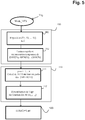
- the rapid acquisition phase 100 of the measurement mode is illustrated in more detail in figure 5 .
- the aim is preferably to have T MES ⁇ 10% T ACQ .
- the image data is acquired for the k values Ti in a single take, by periodically distributing the k values Ti on the pixel matrix.
- the rapid acquisition phase 100 thus comprises a phase 101 of exposure of the pixels, which associates with each pixel of the matrix, a determined exposure time value, among the k values Ti; followed by a phase 102 of rapidly reading the pixels.
- the Ti distribution pattern takes into account the way in which the control lines of the transistors (gates) for initialization and transfer of the pixels in the sensor (topological aspect) and of the capture mode (s) implemented in the sensor are implemented.
- the commands of the initialization and transfer grids are common to the pixels of the same row or of the same column.
- control of the initialization grids which regulate the start of the exposure time is common to the pixels of a same row of the matrix; and the control of the transfer grids, which regulate the end of the exposure time, is common to the pixels of a same column of the matrix.
- control lines of the other pixel transistors are not shown on the figure 2 so as not to overload the drawing unnecessarily.
- This topology which provides for control of the end of exposure of the pixels by column and online reading (by row of pixels), allows a global capture mode. It is not applicable to a shifted capture mode, in which the exposure phase of a row of pixels does not begin until the reading of the previous row of pixels is completed.
- the figure 3 illustrates another topology which allows the two capture modes: the control of the initialization gates and the control of the transfer gates are both common to the pixels of the same row of the matrix.
- the transfer control lines GT l , l equal from 0 to n-1, therefore extend parallel (in the example horizontally) to the corresponding row of pixels, like the initialization control lines GI l .
- control of the initialization grids at the start of the exposure time could be common to the pixels of a same column of the matrix; the selection of pixels for reading could be done by column, etc.
- control modes global, offset
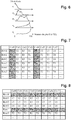
- the values Ti are distributed according to the rows of the columns, regularly (periodically) in the example: T1 on the columns of row 0, 4, 8, etc., ..., T2 on the columns of row 1 , 5, 9, etc., T3 on the columns of row 2, 6, 10, etc. and T4 on the columns of rank 3, 7, 11, etc.
- An image data acquisition phase for the k exposure values Ti then proceeds as follows: the exposure phase begins for all the rows of pixels at the same time (signals GI l activated at the same time) and the sequencer controls the end of exposure control signals GT j as a function of row j of the column according to the pattern defined ( Figure 7 ).
- the on-line reading phase can begin after the end of the matrix exposure phase, set on the longest exposure time, T4 in this case.
- the figure 8 shows another distribution pattern applicable to an array of pixels having the topology of the figure 3 , which allows the sequencer to play on the start of the exposure time (command lines GI l ) to adjust the exposure time of each row and the rest of the timing (end of exposure, playback) which depends on the mode of global capture or shifted, is not jostled by this "game”. More explicitly, rows ordered with a longer exposure time will have their initialization grid command activated relatively sooner and rows ordered with shorter exposure times will have their initialization grid control activated relatively later.
- the value T1 is applied to the rows of rank 0, 4, 8, ...; the value T2, on rows of rank 1, 5, 9, ... etc.
- control lines of the considered sensor which may be that of the figure 2 , of the figure 3 , or another topology
- the sequencing circuit SEQ of the sensor ( Figure 2 ) is configured (programmed) to supply the control signals of the pixels corresponding to this pattern and to the capture mode of the sensor, to control the different phases of the measurement mode.
- T1 and T2 two fairly distant values T1 and T2 are chosen, corresponding respectively to high and low illumination, for example 100 microseconds and 1 millisecond.
- k at least equal to 3 or 4 to cover a wide range of lighting conditions (weak to strong) and improve the reliability and efficiency of the determination of the value Topt for variable operating conditions, for example: outdoors, with highly reflective (eg metal can) or very absorbent (dark paper) objects to analyze.
- the k values Ti will then be advantageously chosen with a ratio R constant between one value and the next, to facilitate the calculations and have the same constraints on the histograms.
- the values Ti are chosen according to the constraints and possibilities of the sequencer.
- a usual reference time for sequencers for signal management is the duration of a read cycle of a row (called row time), in nominal mode (full resolution), which is of the order of 10 microseconds for common technologies.
- row time the duration of a read cycle of a row
- full resolution full resolution
- R the ratio
- the fast reading phase 102 uses one or the other of the two measures described below.
- the first measure is not to read all the pixels in the matrix. It has been verified that one does not need histograms calculated with the data of the complete matrix to effectively determine the Topt value, but the image data must represent the different Ti values applied and allow a good analysis of the Topt value. the exhibition. Sub-sampling of the matrix is therefore proposed, but the selection of the pixels to be read must make it possible to cover the various exposure time values. That is to say that the selection of the sampled pixels takes into account both the way in which the pixels are selected for reading, ie the topology of the sensor, and the distribution pattern of the Ti on the matrix.
- the reading is done by row (row selection lines selr l ), and simultaneously for the m pixels of the selected row, via the m column conductors (cc 0 , ... cc m-1 ) connected to the analog-to-digital conversion means ADC which supply the m corresponding digital values.
- the k values Ti will be distributed according to a periodic pattern, for good temporal homogeneity on the matrix. It is then possible to provide for sampling k consecutive rows every X rows, while preferably keeping, at the scale of the matrix, a sampling of one row out of 8, 16 or 32.
- the reading time of the measurement mode is proportional to the total number of rows read.
- the measurement image reading time can be reduced by targeting one or more areas of interest in the matrix, such as for example a central area ZOI 2 or the areas of angles.
- zones are defined according to the application and cover a set of contiguous pixels in sufficient number to obtain a homogeneous set of spatial and temporal data making it possible to analyze the exposure and to determine the Topt value with good efficiency.
- the fast reading phase of the measurement mode applies horizontal downsampling only to the target zone (s).
- the read circuit is configured in measurement mode to sample 1 row on P over the height y rows with integer P equal to or greater than 1; and for each row sampled, the read circuit will conduct m conversions in parallel, and only the image data supplied by the pixels of the z columns are kept to be processed by the digital processing circuit which sets the desirable value of time d 'exposure.
- a targeting aiming at the sides of the matrix one will preferably exclude the zones of angles to keep only one central zone of the matrix defined for analyzing the image exposure of the target code.
- a central zone of interest ZOI 2 can be defined which covers the 250 rows and 250 central columns.
- By associating a sub-sampling of one row out of 8, we arrive at a reading time reduction factor of 32 (1/4 x 1/8 1/32), with about 30 rows to be read out of the 1000 of the matrix.
- the targeting is aimed at the center, one will preferably exclude a central zone and in measurement mode, one will preferably make the acquisition in the corner zones.
- a second measure for the fast read phase 102 is the reduction in the resolution of the analog-to-digital conversion. For example, reducing the resolution by two bits reduces the conversion time by a factor of 4. This measurement is easily implemented, by means of a Set-q indicator positioned by the sequencer ( figure 2 ) to set the converter resolution. In the invention, provision is made for this indicator to fix for the measurement mode a resolution which is different, reduced, from that of the nominal acquisition mode.
- the fast reading phase 102 will preferably implement the downsampling measurement and the reduced resolution measurement.
- the measurement mode passes to the phase 110 for determining the desirable exposure value Topt for the target code concerned.
- This phase 110 is ensured by the digital processing circuit COMP ( figure 2 ) previously configured in measurement mode by the sequencer via a mode indicator signal (Sel-mode).
- the COMP circuit begins with the phase 111 of calculating the histograms. For this, it has, for each exposure time value, a set of numerical values ⁇ DATA (Ti) ⁇ read from the matrix. Each value corresponds to a gray level over the gray level range encoded by the conversion.
- the histogram calculation on these data (or part of these data corresponding to a selection of gray levels) gives the distribution of the pixels according to the gray levels for this exposure time value Ti: we therefore measure the range of brightness of the target code image, for this exposure time.
- phase 112 for determining the time Topt, from the histograms calculated for the different times Ti.
- the first histogram H 1 at the top of the figure corresponds to an image that is too little exposed, with a high percentage of black pixels and a concentration of the pixels on the lowest gray levels.
- the last histogram H 5 at the bottom of the figure corresponds to an image that is too overexposed with many saturated pixels and a concentration of the pixels on the strongest gray levels.
- the histogram to be reached is that of the middle H 3 , which is rather centered, without or with very few saturated pixels (overexposed) and without or with very few black pixels (underexposed). But for code decoding by a data processing system of a code reader, the histogram H 4 which shows a few saturated pixels is quite suitable.
- an exposure time value Topt is determined in phase 112 which must then make it possible to obtain, in the nominal image acquisition phase, a histogram that looks like these H 3 or H 4 histograms.
- Topt will have a value less than T5, to tend towards a form of histogram such as H 3 or H 4 . If the histogram H 1 corresponds to an exposure time T1, Topt will have a value greater than T1.
- the calculation circuit begins by determining, in phase 112, which histogram has the most useful information (quantity of unsaturated or underexposed pixels). For this, it applies an algorithm for comparing characteristic value (s) or statistic (s) of the k histograms H (Ti), such as mean value, percentage of saturated pixels, or corresponding to a given gray level, etc., then it estimates a desirable time value Topt from the selected histogram.
- the calculation circuit combines the result of at least two comparison algorithms, preferably one based on the average value and the other on a percentage of saturated pixels, to establish as a desirable value of exposure time for the next nominal acquisition phase, the average of the results provided by the algorithms. Also, the determination of the value Topt takes into account the possibilities of the sequencer (reference time, line time).
- the calculation circuit modifies the two corresponding values, time of. exposure Tr and gain G in the REG register of shooting parameters.
- the invention which has just been described, applicable to any CMOS sensor used in an optically readable code reader, makes it possible to considerably improve the response time and consumption of the reader, and to reduce its consumption.
- CMOS sensor used in an optically readable code reader
- Those skilled in the art will know how to make the necessary adaptations as a function of the sensor considered, in particular as a function of the capture modes implemented in the sensor, of the topology of the control lines of the pixel matrix, and of the structure of the pixels. which can be more or less complex depending on whether it implements improved reading schemes, with reading noise reduction (correlated double sampling), gain stages by multiplication of charges, etc.
- the implementation of the method of the invention in a sensor results in an adequate configuration / programming of the sequencer including the programming in memory of tables defining the distribution and sub-sampling schemes, and the different exposure time values. used in measurement mode.
Landscapes
- Physics & Mathematics (AREA)
- Engineering & Computer Science (AREA)
- Electromagnetism (AREA)
- General Physics & Mathematics (AREA)
- Toxicology (AREA)
- General Health & Medical Sciences (AREA)
- Artificial Intelligence (AREA)
- Computer Vision & Pattern Recognition (AREA)
- Health & Medical Sciences (AREA)
- Theoretical Computer Science (AREA)
- Multimedia (AREA)
- Signal Processing (AREA)
- Transforming Light Signals Into Electric Signals (AREA)
- Studio Devices (AREA)
- Facsimile Heads (AREA)
- Facsimile Scanning Arrangements (AREA)
Claims (9)
- Verfahren zum Erfassen eines Bildes von einem oder mehreren Codes, die durch einen elektronischen Bildsensor des CMOS-Typs optisch lesbar sind, der beim Empfang eines externen Triggersignals (Trig) durch den Sensor aktiviert wird und die Aufnahme eines Messbildes umfasst, um einen wünschenswerten Belichtungszeitwert zu bestimmen, wobei der wünschenswerte Belichtungszeitwert dann als aktueller Belichtungszeitwert für alle Pixel der Matrix angewendet wird, um eine nominelle Bildaufnahme zu erzielen, dadurch gekennzeichnet, dass die Messbildaufnahme (Mode-Mes) Folgendes umfasst:- eine den Pixeln gemeinsame Integrationsphase (100), die k verschiedene Belichtungszeitwerte (Ti) der in regelmäßiger Weise in den Reihen oder Spalten der Matrix verteilten Pixel anwendet, wobei jedes Pixel mit einem Belichtungszeitwert unter den k verschiedenen Werten assoziiert ist, wobei k eine ganze Zahl von mindestens 2 ist;- eine schnelle Erfassungsphase (102) von digitalen Bilddaten (DATA(Ti)) für die verschiedenen Belichtungszeitwerte der Pixel, die eine schnelle Lesephase durch Unterabtastung der Reihen der Matrix umfasst; und- eine Phase (110) des Bestimmens des wünschenswerten Belichtungszeitwertes (Topt) durch Vergleichen von Histogrammen, die auf der Basis der in der schnellen Erfassungsphase erhaltenen digitalen Bilddaten für jeden unterschiedlichen Belichtungszeitwert berechnet wurden.
- Erfassungsverfahren nach Anspruch 1, wobei ein periodisches Verteilungsmuster der k Belichtungszeitwerte (Ti) über die Spalten der Matrix angewendet wird.
- Erfassungsverfahren nach Anspruch 1 oder 2, wobei die schnelle Lesephase eine Unterabtastung von Reihen anwendet, die in einem Verhältnis von 1 zu 8, 16 oder 32 ist.
- Erfassungsverfahren nach einem der Ansprüche 1 bis 3, wobei die schnelle Lesephase (102) nur auf eine oder mehrere vordefinierte Zonen der Matrix angewendet wird.
- Erfassungsverfahren nach einem der Ansprüche 1 bis 3 unter Ausschluss von einer oder mehreren vordefinierten Zonen der Pixelmatrix für die schnelle Lesephase (102).
- Erfassungsverfahren nach einem der Ansprüche 1 bis 4 unter Verwendung von Analog-Digital-Wandlern zum Lesen der Pixel, die für die nominelle Bildaufnahme mit einer nominellen Auflösung von mindestens zehn Bit konfiguriert sind und die für die Messbildaufnahme mit einer reduzierten Auflösung von gleich oder weniger als 8 Bit konfiguriert sind.
- Erfassungsverfahren nach einem der vorherigen Ansprüche, wobei die Histogramme für die k verschiedenen Belichtungszeitwerte (T1, ...Tk) des Messmodus auf einer Anzahl von Graustufen berechnet werden, die kleiner ist als die Anzahl von Graustufen entsprechend der Auflösung der Analog-Digital-Wandlungsmittel im Messmodus.
- Erfassungsverfahren nach einem der vorherigen Ansprüche, wobei die Phase (112) des Bestimmens des wünschenswerten Belichtungszeitwertes (Topt) mindestens zwei Histogrammvergleichsalgorithmen anwendet, wobei jeder Algorithmus einen ersten Wert ausgibt und als wünschenswerten Belichtungszeitwert für die folgende nominelle Erfassungsphase den Mittelwert der ersten Werte festlegt.
- Erfassungsverfahren nach einem der vorherigen Ansprüche, wobei die Dauer der Messbildaufnahme etwa 10 % oder weniger der Dauer der nominellen Bildaufnahme beträgt.
Applications Claiming Priority (2)
| Application Number | Priority Date | Filing Date | Title |
|---|---|---|---|
| FR1758086A FR3070779B1 (fr) | 2017-09-01 | 2017-09-01 | Procede d'acquisition d'image par un capteur d'image de type cmos pour la reconnaissance de code lisible optiquement |
| PCT/EP2018/072898 WO2019042890A1 (fr) | 2017-09-01 | 2018-08-24 | Procede d'acquisition d'image par un capteur d'image de type cmos pour la reconnaissance de code lisible optiquement |
Publications (2)
| Publication Number | Publication Date |
|---|---|
| EP3677020A1 EP3677020A1 (de) | 2020-07-08 |
| EP3677020B1 true EP3677020B1 (de) | 2021-08-11 |
Family
ID=60515534
Family Applications (1)
| Application Number | Title | Priority Date | Filing Date |
|---|---|---|---|
| EP18755846.5A Active EP3677020B1 (de) | 2017-09-01 | 2018-08-24 | Verfahren zur bilderfassung durch einen bildsensor vom cmos-typ zur erkennung eines optisch lesbaren codes |
Country Status (8)
| Country | Link |
|---|---|
| US (1) | US10896303B2 (de) |
| EP (1) | EP3677020B1 (de) |
| JP (1) | JP7158465B2 (de) |
| CN (1) | CN111527742B (de) |
| CA (1) | CA3074141A1 (de) |
| FR (1) | FR3070779B1 (de) |
| TW (1) | TWI789418B (de) |
| WO (1) | WO2019042890A1 (de) |
Families Citing this family (5)
| Publication number | Priority date | Publication date | Assignee | Title |
|---|---|---|---|---|
| US10861885B1 (en) * | 2019-05-27 | 2020-12-08 | Novatek Microelectronics Corp. | Method of obtaining image data and related image sensing system |
| CN113132588B (zh) * | 2020-01-15 | 2022-09-27 | 思特威(上海)电子科技股份有限公司 | 用于快速启动成像系统的方法及使用该方法的成像系统 |
| CN111601046B (zh) * | 2020-04-22 | 2022-03-01 | 惠州市德赛西威汽车电子股份有限公司 | 一种暗光环境驾驶状态监测方法 |
| CN115249023A (zh) * | 2021-12-27 | 2022-10-28 | 上海祥承通讯技术有限公司 | 一种基于不同曝光参数的解码方法、设备、介质和系统 |
| CN120529163B (zh) * | 2025-07-15 | 2025-12-23 | 宁波新算技术有限公司 | 一种用于标记识别的照明成像方法与设备 |
Family Cites Families (21)
| Publication number | Priority date | Publication date | Assignee | Title |
|---|---|---|---|---|
| US6860428B1 (en) * | 1998-09-11 | 2005-03-01 | Robotic Vision Systems Inc. | Optical symbologies imager |
| US5756981A (en) * | 1992-02-27 | 1998-05-26 | Symbol Technologies, Inc. | Optical scanner for reading and decoding one- and-two-dimensional symbologies at variable depths of field including memory efficient high speed image processing means and high accuracy image analysis means |
| US5521366A (en) * | 1994-07-26 | 1996-05-28 | Metanetics Corporation | Dataform readers having controlled and overlapped exposure integration periods |
| WO1996013798A2 (en) * | 1994-10-25 | 1996-05-09 | United Parcel Service Of America, Inc. | Automatic electronic camera for label image capture |
| US5777313A (en) * | 1995-03-29 | 1998-07-07 | Sanyo Electric Co., Ltd. | Optical code reading apparatus |
| EP0957448A3 (de) * | 1998-05-15 | 2001-09-26 | PSC Scanning, Inc. | Maus mit optischem Codeleser |
| US7128266B2 (en) * | 2003-11-13 | 2006-10-31 | Metrologic Instruments. Inc. | Hand-supportable digital imaging-based bar code symbol reader supporting narrow-area and wide-area modes of illumination and image capture |
| US7490774B2 (en) * | 2003-11-13 | 2009-02-17 | Metrologic Instruments, Inc. | Hand-supportable imaging based bar code symbol reader employing automatic light exposure measurement and illumination control subsystem integrated therein |
| US7607581B2 (en) * | 2003-11-13 | 2009-10-27 | Metrologic Instruments, Inc. | Digital imaging-based code symbol reading system permitting modification of system features and functionalities |
| US20060011724A1 (en) * | 2004-07-15 | 2006-01-19 | Eugene Joseph | Optical code reading system and method using a variable resolution imaging sensor |
| US7780089B2 (en) * | 2005-06-03 | 2010-08-24 | Hand Held Products, Inc. | Digital picture taking optical reader having hybrid monochrome and color image sensor array |
| EP3905099B8 (de) | 2005-03-11 | 2023-03-22 | Hand Held Products, Inc. | Strichcode-lesegerät mit globaler elektronischer verschlusssteuerung |
| DE602005013404D1 (de) * | 2005-11-28 | 2009-04-30 | St Microelectronics Res & Dev | Belichtungseinstellung in einem Maschinenvisionssystem |
| US7815120B2 (en) * | 2008-12-12 | 2010-10-19 | Symbol Technologies, Inc. | Electronic shutter for a dual-mode imager |
| JP5264541B2 (ja) | 2009-02-04 | 2013-08-14 | キヤノン株式会社 | 撮像装置及びその制御方法 |
| US8692913B2 (en) * | 2010-03-16 | 2014-04-08 | Fujifilm Corporation | Solid-state electronic image sensing apparatus and method of controlling operation of same |
| US8866928B2 (en) * | 2012-12-18 | 2014-10-21 | Google Inc. | Determining exposure times using split paxels |
| FR3012002B1 (fr) | 2013-10-16 | 2016-12-23 | E2V Semiconductors | Capteur d'image avec generation de sequences de signaux de commande |
| JP6467190B2 (ja) * | 2014-10-20 | 2019-02-06 | キヤノン株式会社 | 露出制御装置及びその制御方法、撮像装置、プログラム、記憶媒体 |
| EP3318176A4 (de) * | 2015-07-03 | 2019-03-27 | Olympus Corporation | Bildverarbeitungsvorrichtung, bildbestimmungsverfahren und endoskopsystem |
| JP7188870B2 (ja) * | 2017-05-31 | 2022-12-13 | 株式会社キーエンス | 画像検査装置 |
-
2017
- 2017-09-01 FR FR1758086A patent/FR3070779B1/fr active Active
-
2018
- 2018-08-24 JP JP2020512568A patent/JP7158465B2/ja active Active
- 2018-08-24 WO PCT/EP2018/072898 patent/WO2019042890A1/fr not_active Ceased
- 2018-08-24 CA CA3074141A patent/CA3074141A1/en active Pending
- 2018-08-24 US US16/643,116 patent/US10896303B2/en active Active
- 2018-08-24 CN CN201880056928.8A patent/CN111527742B/zh active Active
- 2018-08-24 EP EP18755846.5A patent/EP3677020B1/de active Active
- 2018-08-28 TW TW107129933A patent/TWI789418B/zh not_active IP Right Cessation
Also Published As
| Publication number | Publication date |
|---|---|
| US10896303B2 (en) | 2021-01-19 |
| JP2020532249A (ja) | 2020-11-05 |
| TWI789418B (zh) | 2023-01-11 |
| JP7158465B2 (ja) | 2022-10-21 |
| TW201921913A (zh) | 2019-06-01 |
| US20200394373A1 (en) | 2020-12-17 |
| FR3070779B1 (fr) | 2019-09-13 |
| EP3677020A1 (de) | 2020-07-08 |
| WO2019042890A1 (fr) | 2019-03-07 |
| FR3070779A1 (fr) | 2019-03-08 |
| CA3074141A1 (en) | 2019-03-07 |
| CN111527742B (zh) | 2022-02-22 |
| CN111527742A (zh) | 2020-08-11 |
Similar Documents
| Publication | Publication Date | Title |
|---|---|---|
| EP3677020B1 (de) | Verfahren zur bilderfassung durch einen bildsensor vom cmos-typ zur erkennung eines optisch lesbaren codes | |
| US8336778B2 (en) | Graphical code readers that provide sequenced illumination for glare reduction | |
| US8295601B2 (en) | Indicia reading terminal having multiple exposure periods and methods for same | |
| US9251392B2 (en) | Indicia reading apparatus | |
| US6585159B1 (en) | Indicia sensor system for optical reader | |
| US10810392B2 (en) | Barcode reader | |
| CN105246395B (zh) | 综合固定模式噪声消除 | |
| EP2538680A2 (de) | Indizienleseendgerät mit Farbrahmenverarbeitung | |
| KR20200134374A (ko) | 이미지 신호 프로세서의 모델링 방법, 및 전자 기기 | |
| WO2011048302A1 (fr) | Procede, programme d'ordinateur et dispositif de suivi hybride de representations d'objets, en temps reel, dans une sequence d'images | |
| FR2939920A1 (fr) | Capteur matriciel | |
| US20090078773A1 (en) | Multiple Configuration Image Scanner | |
| US20240259706A1 (en) | Systems, methods, and media for high dynamic range imaging using single-photon and conventional image sensor data | |
| US8215554B2 (en) | Graphical code readers for balancing decode capability and speed by using image brightness information | |
| US11233936B2 (en) | Method and electronic device for recommending image capture mode | |
| WO2020094441A1 (fr) | Capteur d'image pour la reconnaissance optique de code(s) | |
| FR3148093A1 (fr) | Gestion d’échec de télémétrie de moteurs de balayage | |
| FR2968876A1 (fr) | Systeme d'acquisition d'images presentant une dynamique elevee | |
| EP4186227B1 (de) | Flugzeitsensor für abstandsmessung mit pixel mit mehreren speicherknoten | |
| FR3148092A1 (fr) | Gestion d’échec de télémétrie de moteurs de balayage | |
| FR2826222A1 (fr) | Procede d'utilisation d'une camera thermique, dispositif pour sa mise en oeuvre, et camera thermique incorporant un tel dispositif | |
| US20130175345A1 (en) | Indicia reading terminal having dynamic decodable indicia representation search | |
| FR3074383A1 (fr) | Procede de reception d’un signal lumineux module de type signal vlc | |
| WO2018178104A1 (fr) | Procédé et dispositif d'acquisition et de restitution d'images numériques avec une dynamique étendue |
Legal Events
| Date | Code | Title | Description |
|---|---|---|---|
| STAA | Information on the status of an ep patent application or granted ep patent |
Free format text: STATUS: UNKNOWN |
|
| STAA | Information on the status of an ep patent application or granted ep patent |
Free format text: STATUS: THE INTERNATIONAL PUBLICATION HAS BEEN MADE |
|
| PUAI | Public reference made under article 153(3) epc to a published international application that has entered the european phase |
Free format text: ORIGINAL CODE: 0009012 |
|
| STAA | Information on the status of an ep patent application or granted ep patent |
Free format text: STATUS: REQUEST FOR EXAMINATION WAS MADE |
|
| 17P | Request for examination filed |
Effective date: 20200220 |
|
| AK | Designated contracting states |
Kind code of ref document: A1 Designated state(s): AL AT BE BG CH CY CZ DE DK EE ES FI FR GB GR HR HU IE IS IT LI LT LU LV MC MK MT NL NO PL PT RO RS SE SI SK SM TR |
|
| AX | Request for extension of the european patent |
Extension state: BA ME |
|
| DAV | Request for validation of the european patent (deleted) | ||
| DAX | Request for extension of the european patent (deleted) | ||
| GRAP | Despatch of communication of intention to grant a patent |
Free format text: ORIGINAL CODE: EPIDOSNIGR1 |
|
| STAA | Information on the status of an ep patent application or granted ep patent |
Free format text: STATUS: GRANT OF PATENT IS INTENDED |
|
| INTG | Intention to grant announced |
Effective date: 20210503 |
|
| GRAS | Grant fee paid |
Free format text: ORIGINAL CODE: EPIDOSNIGR3 |
|
| GRAA | (expected) grant |
Free format text: ORIGINAL CODE: 0009210 |
|
| STAA | Information on the status of an ep patent application or granted ep patent |
Free format text: STATUS: THE PATENT HAS BEEN GRANTED |
|
| AK | Designated contracting states |
Kind code of ref document: B1 Designated state(s): AL AT BE BG CH CY CZ DE DK EE ES FI FR GB GR HR HU IE IS IT LI LT LU LV MC MK MT NL NO PL PT RO RS SE SI SK SM TR |
|
| REG | Reference to a national code |
Ref country code: CH Ref legal event code: EP |
|
| REG | Reference to a national code |
Ref country code: DE Ref legal event code: R096 Ref document number: 602018021728 Country of ref document: DE |
|
| REG | Reference to a national code |
Ref country code: IE Ref legal event code: FG4D Free format text: LANGUAGE OF EP DOCUMENT: FRENCH Ref country code: AT Ref legal event code: REF Ref document number: 1420590 Country of ref document: AT Kind code of ref document: T Effective date: 20210915 |
|
| REG | Reference to a national code |
Ref country code: LT Ref legal event code: MG9D |
|
| REG | Reference to a national code |
Ref country code: NL Ref legal event code: MP Effective date: 20210811 |
|
| REG | Reference to a national code |
Ref country code: AT Ref legal event code: MK05 Ref document number: 1420590 Country of ref document: AT Kind code of ref document: T Effective date: 20210811 |
|
| PG25 | Lapsed in a contracting state [announced via postgrant information from national office to epo] |
Ref country code: PT Free format text: LAPSE BECAUSE OF FAILURE TO SUBMIT A TRANSLATION OF THE DESCRIPTION OR TO PAY THE FEE WITHIN THE PRESCRIBED TIME-LIMIT Effective date: 20211213 Ref country code: NO Free format text: LAPSE BECAUSE OF FAILURE TO SUBMIT A TRANSLATION OF THE DESCRIPTION OR TO PAY THE FEE WITHIN THE PRESCRIBED TIME-LIMIT Effective date: 20211111 Ref country code: LT Free format text: LAPSE BECAUSE OF FAILURE TO SUBMIT A TRANSLATION OF THE DESCRIPTION OR TO PAY THE FEE WITHIN THE PRESCRIBED TIME-LIMIT Effective date: 20210811 Ref country code: BG Free format text: LAPSE BECAUSE OF FAILURE TO SUBMIT A TRANSLATION OF THE DESCRIPTION OR TO PAY THE FEE WITHIN THE PRESCRIBED TIME-LIMIT Effective date: 20211111 Ref country code: AT Free format text: LAPSE BECAUSE OF FAILURE TO SUBMIT A TRANSLATION OF THE DESCRIPTION OR TO PAY THE FEE WITHIN THE PRESCRIBED TIME-LIMIT Effective date: 20210811 Ref country code: RS Free format text: LAPSE BECAUSE OF FAILURE TO SUBMIT A TRANSLATION OF THE DESCRIPTION OR TO PAY THE FEE WITHIN THE PRESCRIBED TIME-LIMIT Effective date: 20210811 Ref country code: SE Free format text: LAPSE BECAUSE OF FAILURE TO SUBMIT A TRANSLATION OF THE DESCRIPTION OR TO PAY THE FEE WITHIN THE PRESCRIBED TIME-LIMIT Effective date: 20210811 Ref country code: HR Free format text: LAPSE BECAUSE OF FAILURE TO SUBMIT A TRANSLATION OF THE DESCRIPTION OR TO PAY THE FEE WITHIN THE PRESCRIBED TIME-LIMIT Effective date: 20210811 Ref country code: ES Free format text: LAPSE BECAUSE OF FAILURE TO SUBMIT A TRANSLATION OF THE DESCRIPTION OR TO PAY THE FEE WITHIN THE PRESCRIBED TIME-LIMIT Effective date: 20210811 Ref country code: FI Free format text: LAPSE BECAUSE OF FAILURE TO SUBMIT A TRANSLATION OF THE DESCRIPTION OR TO PAY THE FEE WITHIN THE PRESCRIBED TIME-LIMIT Effective date: 20210811 |
|
| PG25 | Lapsed in a contracting state [announced via postgrant information from national office to epo] |
Ref country code: PL Free format text: LAPSE BECAUSE OF FAILURE TO SUBMIT A TRANSLATION OF THE DESCRIPTION OR TO PAY THE FEE WITHIN THE PRESCRIBED TIME-LIMIT Effective date: 20210811 Ref country code: LV Free format text: LAPSE BECAUSE OF FAILURE TO SUBMIT A TRANSLATION OF THE DESCRIPTION OR TO PAY THE FEE WITHIN THE PRESCRIBED TIME-LIMIT Effective date: 20210811 Ref country code: GR Free format text: LAPSE BECAUSE OF FAILURE TO SUBMIT A TRANSLATION OF THE DESCRIPTION OR TO PAY THE FEE WITHIN THE PRESCRIBED TIME-LIMIT Effective date: 20211112 |
|
| PG25 | Lapsed in a contracting state [announced via postgrant information from national office to epo] |
Ref country code: NL Free format text: LAPSE BECAUSE OF FAILURE TO SUBMIT A TRANSLATION OF THE DESCRIPTION OR TO PAY THE FEE WITHIN THE PRESCRIBED TIME-LIMIT Effective date: 20210811 |
|
| PG25 | Lapsed in a contracting state [announced via postgrant information from national office to epo] |
Ref country code: DK Free format text: LAPSE BECAUSE OF FAILURE TO SUBMIT A TRANSLATION OF THE DESCRIPTION OR TO PAY THE FEE WITHIN THE PRESCRIBED TIME-LIMIT Effective date: 20210811 |
|
| REG | Reference to a national code |
Ref country code: DE Ref legal event code: R097 Ref document number: 602018021728 Country of ref document: DE |
|
| PG25 | Lapsed in a contracting state [announced via postgrant information from national office to epo] |
Ref country code: SM Free format text: LAPSE BECAUSE OF FAILURE TO SUBMIT A TRANSLATION OF THE DESCRIPTION OR TO PAY THE FEE WITHIN THE PRESCRIBED TIME-LIMIT Effective date: 20210811 Ref country code: SK Free format text: LAPSE BECAUSE OF FAILURE TO SUBMIT A TRANSLATION OF THE DESCRIPTION OR TO PAY THE FEE WITHIN THE PRESCRIBED TIME-LIMIT Effective date: 20210811 Ref country code: RO Free format text: LAPSE BECAUSE OF FAILURE TO SUBMIT A TRANSLATION OF THE DESCRIPTION OR TO PAY THE FEE WITHIN THE PRESCRIBED TIME-LIMIT Effective date: 20210811 Ref country code: MC Free format text: LAPSE BECAUSE OF FAILURE TO SUBMIT A TRANSLATION OF THE DESCRIPTION OR TO PAY THE FEE WITHIN THE PRESCRIBED TIME-LIMIT Effective date: 20210811 Ref country code: LU Free format text: LAPSE BECAUSE OF NON-PAYMENT OF DUE FEES Effective date: 20210824 Ref country code: EE Free format text: LAPSE BECAUSE OF FAILURE TO SUBMIT A TRANSLATION OF THE DESCRIPTION OR TO PAY THE FEE WITHIN THE PRESCRIBED TIME-LIMIT Effective date: 20210811 Ref country code: CZ Free format text: LAPSE BECAUSE OF FAILURE TO SUBMIT A TRANSLATION OF THE DESCRIPTION OR TO PAY THE FEE WITHIN THE PRESCRIBED TIME-LIMIT Effective date: 20210811 Ref country code: AL Free format text: LAPSE BECAUSE OF FAILURE TO SUBMIT A TRANSLATION OF THE DESCRIPTION OR TO PAY THE FEE WITHIN THE PRESCRIBED TIME-LIMIT Effective date: 20210811 |
|
| PLBE | No opposition filed within time limit |
Free format text: ORIGINAL CODE: 0009261 |
|
| STAA | Information on the status of an ep patent application or granted ep patent |
Free format text: STATUS: NO OPPOSITION FILED WITHIN TIME LIMIT |
|
| 26N | No opposition filed |
Effective date: 20220512 |
|
| PG25 | Lapsed in a contracting state [announced via postgrant information from national office to epo] |
Ref country code: IT Free format text: LAPSE BECAUSE OF FAILURE TO SUBMIT A TRANSLATION OF THE DESCRIPTION OR TO PAY THE FEE WITHIN THE PRESCRIBED TIME-LIMIT Effective date: 20210811 Ref country code: IE Free format text: LAPSE BECAUSE OF NON-PAYMENT OF DUE FEES Effective date: 20210824 |
|
| PG25 | Lapsed in a contracting state [announced via postgrant information from national office to epo] |
Ref country code: SI Free format text: LAPSE BECAUSE OF FAILURE TO SUBMIT A TRANSLATION OF THE DESCRIPTION OR TO PAY THE FEE WITHIN THE PRESCRIBED TIME-LIMIT Effective date: 20210811 |
|
| REG | Reference to a national code |
Ref country code: DE Ref legal event code: R079 Ref document number: 602018021728 Country of ref document: DE Free format text: PREVIOUS MAIN CLASS: H04N0005353000 Ipc: H04N0025530000 |
|
| PG25 | Lapsed in a contracting state [announced via postgrant information from national office to epo] |
Ref country code: CY Free format text: LAPSE BECAUSE OF FAILURE TO SUBMIT A TRANSLATION OF THE DESCRIPTION OR TO PAY THE FEE WITHIN THE PRESCRIBED TIME-LIMIT Effective date: 20210811 |
|
| PG25 | Lapsed in a contracting state [announced via postgrant information from national office to epo] |
Ref country code: HU Free format text: LAPSE BECAUSE OF FAILURE TO SUBMIT A TRANSLATION OF THE DESCRIPTION OR TO PAY THE FEE WITHIN THE PRESCRIBED TIME-LIMIT; INVALID AB INITIO Effective date: 20180824 |
|
| PG25 | Lapsed in a contracting state [announced via postgrant information from national office to epo] |
Ref country code: MK Free format text: LAPSE BECAUSE OF FAILURE TO SUBMIT A TRANSLATION OF THE DESCRIPTION OR TO PAY THE FEE WITHIN THE PRESCRIBED TIME-LIMIT Effective date: 20210811 |
|
| PG25 | Lapsed in a contracting state [announced via postgrant information from national office to epo] |
Ref country code: MT Free format text: LAPSE BECAUSE OF FAILURE TO SUBMIT A TRANSLATION OF THE DESCRIPTION OR TO PAY THE FEE WITHIN THE PRESCRIBED TIME-LIMIT Effective date: 20210811 |
|
| PGFP | Annual fee paid to national office [announced via postgrant information from national office to epo] |
Ref country code: DE Payment date: 20250812 Year of fee payment: 8 |
|
| PGFP | Annual fee paid to national office [announced via postgrant information from national office to epo] |
Ref country code: BE Payment date: 20250826 Year of fee payment: 8 Ref country code: GB Payment date: 20250826 Year of fee payment: 8 |
|
| PGFP | Annual fee paid to national office [announced via postgrant information from national office to epo] |
Ref country code: FR Payment date: 20250828 Year of fee payment: 8 |
|
| PGFP | Annual fee paid to national office [announced via postgrant information from national office to epo] |
Ref country code: CH Payment date: 20250901 Year of fee payment: 8 |
|
| PG25 | Lapsed in a contracting state [announced via postgrant information from national office to epo] |
Ref country code: TR Free format text: LAPSE BECAUSE OF FAILURE TO SUBMIT A TRANSLATION OF THE DESCRIPTION OR TO PAY THE FEE WITHIN THE PRESCRIBED TIME-LIMIT Effective date: 20210811 |