EP3677111A1 - Früchtepflück- und sammelvorichtung - Google Patents
Früchtepflück- und sammelvorichtung Download PDFInfo
- Publication number
- EP3677111A1 EP3677111A1 EP19000593.4A EP19000593A EP3677111A1 EP 3677111 A1 EP3677111 A1 EP 3677111A1 EP 19000593 A EP19000593 A EP 19000593A EP 3677111 A1 EP3677111 A1 EP 3677111A1
- Authority
- EP
- European Patent Office
- Prior art keywords
- basket
- wall
- slots
- collecting container
- base
- Prior art date
- Legal status (The legal status is an assumption and is not a legal conclusion. Google has not performed a legal analysis and makes no representation as to the accuracy of the status listed.)
- Granted
Links
Images


Classifications
-
- A—HUMAN NECESSITIES
- A01—AGRICULTURE; FORESTRY; ANIMAL HUSBANDRY; HUNTING; TRAPPING; FISHING
- A01D—HARVESTING; MOWING
- A01D46/00—Picking of fruits, vegetables, hops, or the like; Devices for shaking trees or shrubs
- A01D46/24—Devices for picking apples or like fruit
- A01D46/247—Manually operated fruit-picking tools
Definitions
- the invention relates to a fruit picking and collecting device according to claims 1, 3 and 8.
- the AT 1493858 B describes a fruit picking device with a ring attached to a stem, the upper edge of which is provided with recesses. With this ring, the fruit is released from its stem and falls into a bag or sack attached to the ring below. If several fruits are picked, the newly picked fruit falls on the one already in the sack and can damage it. For emptying, the fruit picker has to be brought to a box and emptied, which can lead to further possible damage to the fruit already in the box.
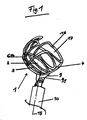
- the Figures 1 and 2nd show the fruit picking and collecting device 1 according to claim 1. It consists of a basket-shaped collecting container 2, consisting of a spherically curved basket bottom 3 and a spherical basket wall 4. At the edge of the basket bottom 3 in the area of the transition point / line 6, 14 basket bottom 3 / basket wall 4 there is a flat tab 9, which caters in the opposite direction to the basket opening 7 and whose surface 9.1 is aligned parallel to the center line 15 of the basket, to which the handle 10 can be fastened.
- the basket wall 4 of the collecting container 2 has three slots 5, 12, 13. The first slot 5 lies opposite the tab 9 on the same basket center line 15.
- the center lines 18, 19 of the two other slots 12, 13 are arranged to the left and right of the first slot 5 at an angle ⁇ of preferably 45 °, measured at the transition line 6, 14 basket bottom 3 / basket wall 4.
- the slots 12, 13 also have a preferred width of about 30 mm, also extend from the upper end 16 of the basket wall 4 to the transition point / line 6/14 basket floor 3 / basket wall 4, but are based on the vertical 20 at the transition point / line 6, 14 basket bottom 3 / basket wall 4 inclined by an angle ⁇ of preferably 20 ° in the direction of the tab 9.
- the collecting container 2 is pivotable at the connection point handle 10 / tab 9 relative to the handle 10 parallel to the tab 9 / handle axis.
- the collecting container 2 has the preferred dimensions of approximately 120 mm in diameter at the transition point / line 6, 14 basket base 3 / basket wall 4, approximately 160 mm in diameter at half height 11 of the basket wall 4 and approximately 120 mm in diameter at the upper end 16 of the Basket wall 4. However, the dimensions can be adapted to the area of application.
- the fruit picking and collecting device 1 can be made from bent wire.
- the wire spacing in the case of the collecting container wall and bottom is preferably approximately 30 mm.
- Another possibility of production is to manufacture the device by injection molding.
- the use of transparent material can also be used to produce a collecting container which is closed except for the slots, since the material is transparent. If the collecting container is made of opaque plastic similar to a wire construction, the preferred distance between the construction elements is also approx. 30 mm.
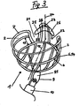
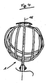
- the Figures 3 and 4th show the fruit picking and collecting device 1 according to claim 3. It consists of a basket-shaped collecting container 2, consisting of a curved basket bottom 3 and a spherical basket wall 4. At the edge of the basket bottom 3 in the area of the transition / line 6, 14 basket bottom 3 / basket wall 4 is a flat tab 9 pointing in the opposite direction to the basket opening 7, the surface 9.1 of which is aligned parallel to the center line 15 of the basket, to which the handle 10 can be fastened.
- the basket wall 4 of the collecting container 2 has two slots 21, 22.
- the slots 21, 22 are separated by a wall element 23 opposite the tab 9, the center line 24 of which is perpendicular to the center line 15 of the basket base and perpendicular to the circumferential line 14 of the basket base, the wall element 23 having a preferred width of approximately 40 mm .
- Approx. 2/3 of the height of the wall element 23 has a stem separating element 25, 26 extending into the respective slot 21, 22 on both sides of the wall element 23. This element covers approximately 1/3 of the slot width and is provided with a cutting edge 27 on the side facing the basket bottom 3. The cutting edge 27 is inclined towards the basket base 3 from the vertical at an angle ⁇ of 65 ° to 85 °.
- the Handle separation elements 25, 26 can also be combined in an extra component 28 and attached to the outside of the wall element 23. If the collecting container is made of opaque plastic similar to a wire construction, the preferred distance between the construction elements is also approx. 30 mm.
- a picking and harvesting process is described below.
- the inclination of the harvest container 2 relative to the handle 10 is adjusted appropriately.
- the collecting container 2 is now moved towards the fruit from below or from the side in such a way that the fruit in the collecting container 2 and the stem of the fruit move in one of the slots 5, 12, 13 or 21. 22 or 38 to 45.
- the transparency of the collecting container 2 is urgently required.
- the fruit can now be separated from the branch by gently pulling and rotating the collecting container 2 and thus lies in the collecting container 2.
- the stem of the fruit can be broken off. This roughly corresponds to a manual picking process.
- the collecting container 2 is emptied from the picking person's stand by moving the collecting container 2 to a transport container and emptying it there by rotating the collecting container 2. This means that the fruit picking and collecting device in a transport container possible without touching the fruit by hand.
- the device is also suitable for picking up fruit from the ground without a change. Drain as described above.
Landscapes
- Life Sciences & Earth Sciences (AREA)
- Environmental Sciences (AREA)
- Harvesting Machines For Specific Crops (AREA)
Abstract
Description
- Die Erfindung betrifft eine Früchtepflück- und Sammelvorrichtung nach den Patentansprüchen 1, 3 und 8.
- Die
AT 1493858 B - Somit ist es die Aufgabe der Erfindung, eine Früchtepflück- und Sammelvorrichtung anzubieten, die das Pflücken und Entleeren der Vorrichtung für den Anwender komfortabler macht und die gepflückten Früchte nicht beschädigt.
- Diese Aufgabe wird durch eine Vorrichtung mit den Merkmalen der Patentansprüche 1, 3 und 8
gelöst. - Weitere Ausgestaltungen der Erfindung sind in den Unteransprüchen angegeben.
- Ausführungsbeispiele der Erfindung werden nachfolgend anhand der Figuren naher erläutert.
- Die
Figuren 1 und2 zeigen die Früchtepflück- und Sammelvorrichtung 1 gemäß Patentanspruch 1. Sie besteht aus einem korbförmigen Sammelbehälter 2, bestehend aus einem kugelförmig nach unten gewölbten Korbboden 3 und einer kugelförmig ausgebildeten Korbwand 4. Am Rand des Korbbodens 3 im Bereich der Übergangsstelle/ linie 6, 14 Korbboden 3/ Korbwand 4 ist eine in die entgegengesetzte Richtung zur Korböffnung 7 welsende flächige Lasche 9, deren Fläche 9.1 parallel zur Mittellinie 15 des Korbes ausgerichtet ist, angebracht, an der der Stiel 10 befestigbar ist. Die Korbwand 4 des Sammelbehälters 2 weist drei Schlitze 5, 12, 13 auf. Der erste Schlitz 5 liegt der Lasche 9 gegenüber auf derselben Korbmittellinie 15. Er hat eine Breite von bevorzugt ca. 30 mm, reicht vom oberen Ende 16 der Korbwand 4 bis zur Übergangsstelle/ linie 6, 14 Korbboden 3/ Korbwand 4. Seine Mittellinie 17 ist parallel zur Lasche 9 ausgerichtet. Die Mittellinien 18, 19 der beiden anderen Schlitze 12, 13 sind links und rechts des ersten Schlitzes 5 in einem Winkel α von bevorzugt 45°, gemessen an der Übergangslinie 6, 14 Korbboden 3/ Korbwand 4 angeordnet. Die Schlitze 12, 13 weisen ebenfalls eine bevorzugte Breite von ca. 30 mm auf, reichen ebenfalls vom oberen Ende 16 der Korbwand 4 bis zur Übergangstelle/ linie 6/ 14 Korbboden 3/ Korbwand 4, sind jedoch ausgehend von der Senkrechten 20 auf der Übergangsstelle/ linie 6, 14 Korbboden 3/ Korbwand 4 um einen Winkel β von bevorzugt 20° in Richtung der Lasche 9 geneigt.
Der Sammelbehälter 2 ist an der Verbindungsstelle Stiel 10 / Lasche 9 relativ zum Stiel 10 parallel zur Lasche 9/ Stielachse verschwenkbar. Der Sammelbehälter 2 hat die bevorzugten Abmessungen von ca. 120 mm Durchmesser an der Übergangsstelle/ linie 6, 14 Korbboden 3/ Korbwand 4, ca. 160 mm Durchmesser auf halber Höhe 11 der Korbwand 4 und ca. 120 mm Durchmesser am oberen Ende 16 der Korbwand 4. Die Abmessungen können jedoch dem Einsatzgebiet angepasst werden. - Sichergestellt werden muss jedoch die Neigung der Schlitze 12, 13 links und rechts des mittleren Schlitzes 5
In einer Ausführungsform kann die Früchtepflück- und Sammelvorrichtung 1 aus gebogenem Draht gefertigt sein. Der Drahtabstand bei Sammelbehälterwand - und Boden beträgt hierbei vorzugsweise ca. 30 mm, Eine andere Möglichkeit der Fertigung besteht darin, die Vorrichtung durch Spritzgießen herzustellen. Hierbei kann durch die Verwendung von durchsichtigem Material auch ein bis auf die Schlitze geschlossener Sammelbehälter gefertigt werden, da das Material durchschaubar ist. Wenn der Sammelbehälter aus undurchsichtigem Kunststoff ähnlich einer Drahtkonstruktion hergestellt wird, ist auch hier der bevorzugte Abstand der Konstruktionselemente ca. 30 mm. - Die
Figuren 3 und4 zeigen die Früchtepflück- und Sammelvorrichtung 1 gemäß Patentanspruch 3. Sie besteht aus einem korbförmigen Sammelbehälter 2, bestehend aus einem gewölbten Korbboden 3 und einer kugelförmig ausgebildeten Korbwand 4. Am Rand des Korbbodens 3 im Bereich der Übergangsstelle/ linie 6, 14 Korbboden 3/ Korbwand 4 ist eine in die entgegengesetzte Richtung zur Korböffnung 7 weisende flächige Lasche 9, deren Fläche 9.1 parallel zur Mittellinie 15 des Korbes ausgerichtet ist, angebracht, an der der Stiel 10 befestigbar ist. Die Korbwand 4 des Sammelbehälters 2 weist zwei Schlitze 21, 22 auf. Die Schlitze 21, 22 sind durch ein der Lasche 9 gegenüberliegendes Wandelement 23, dessen Mittellinie 24 senkrecht auf der Mittellinie 15 des Korbbodens und senkrecht auf der Umfangslinie 14 des Korbbodens steht, getrennt, wobei das Wandelement 23 eine bevorzugte Breite von ca. 40 mm aufweist. In ca. 2/3 der Höhe des Wandelements 23 ist beidseitig des Wandelements 23 ein in den jeweiligen Schlitz 21, 22 reichendes Stielabtrennelement 25, 26 angebracht. Dieses Element deckt ca. 1/3 der Schlitzbreite ab und ist auf der zum Korbboden 3 weisenden Seite mit einer Schneide 27 versehen. Die Schneide 27 ist zum Korbboden 3 hin von der Senkrechten in einem Winkel γ von 65° bis 85 ° geneigt. Die Stielabtrennelemente 25, 26 können auch in einem Extrabauteil 28 zusammengefasst und außen an dem Wandelement 23 angebracht sein. Wenn der Sammelbehälter aus undurchsichtigem Kunststoff ähnlich einer Drahtkonstruktion hergestellt wird, ist auch hier der bevorzugte Abstand der Konstruktionselemente ca. 30 mm. - Die
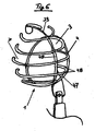
Figuren 5 und6 zeigen die Früchtepflück- und Sammelvorrichtung 1 gemäß Patentanspruch 8. Sie besteht aus einem korbförmigen Sammelbehälter 2, bestehend aus einem gewölbten Korbboden 3 und einer kugelförmig ausgebildeten Korbwand 4.
In diesem Lösungsvorschlag wird der Sammelbehälter 2 ausgehend von einem Ring 47 aufgebaut, in den mit einem Abstand von bevorzugt 30 mm einstückige und ensprechend einer Kugeloberfläche geformte Boden-Wandelemente 48 eingefügt und befestigt sind. Zwischen diesen Boden-Wandelementen 48 entstehen die Schlitze 38 bis 45, die durch die Wandelemente 29 bis 37 getrennt sind. Quer dazu ist ein ebenso entlang einer Kugeloberfläche geformtes Boden-Wandelement 49 angebracht, das in dem Wandelement 33 endet. An diesem Wandelement ist in etwa 2/3 der Wandhöhe ein in die Schlitze 41, 42 reichendes Stielabtrennelement 46 angebracht. Das Stielabtrennelement 46 deckt ca. 1/3 der Schlitzbreite der Schlitze 41, 42 ab und ist auf der zum Korbboden 3 weisenden Seite mit einer Schneide 27 versehen. Die Schneide 27 ist zum Korbboden 3 hin in einem Winkel γ von 65° bis 85 ° geneigt. Dem Wandelement 33 gegenüber ist auf dem Boden-Wandelement 49 mit Bereich des Rings 47 eine Lasche 9 zur Befestigung des Stiels 10 angebracht. Der Sammelkorb 2 wird auf der Laschenseite durch ein gebogenes Oval 50, das am über den Ring 47 hinausragenden Ende des Quer - Boden-Wandelement 49 angebracht ist, abgeschlossen.
Es ist jedoch auch möglich, den Korbboden 3 geschlossen aus durchsichtigem Kunststoff zu fertigen, an den sich die die Schlitze trennenden Wandelemente anschließen. - Für alle mit den Patentansprüchen 1, 3 und 8 vorgeschlagenen Lösungen gilt, dass der Sammelbehälter 2 aus allen dafür einsetzbaren Materiallen wie z. B. Metall oder Kunststoff gefertigt werden kann. Es soll jedoch sichergestellt sein, dass der Sammelbehälter 2 durchschaubar ist. Im Falle der Verwendung von sichtdichten Materialien wie Metall oder eingefärbtem Kunststoff darf er deshalb keine geschlossenen Flächen aufweisen. Im Falle der Verwendung von durchsichtigem Kunststoff kann der Sammelbehälter, je nach Lösungsvariante, auch geschlossenwandig oder teilweise geschlossenwandig ausgeführt sein.
- Die in der Lösung nach Anspruch 1 angegebenen Maße sind auch auf die Lösungen nach Anspruch 3 und 8 anwendbar.
- Im Folgenden wird ein Pflück - und Erntevorgang beschrieben. Je nach Standplatz der pflückenden Person wird die Neigung des sarnmelbehatters 2 relativ zum Stiel 10 passend eingestellt. Je nach Lage der zu Druckenden Frucht am Baum wird der Sammelbehälter 2 nun von unten oder von der Seite an die Frucht so heranbewegt, dass sich die Frucht im Sammelbehälter 2 und der Stiel der Frucht in einem der Schlitze 5, 12, 13 oder 21, 22 oder 38 bis 45 befindet. Hierzu ist die Durchschaubarkeit des Sammelbehälters 2 dringend erforderlich. Die Frucht kann nun durch leichtes Ziehen und Drehen des Sammelbehälters 2 vom Zweig getrennt werden und liegt somit Im Sammelbehälter 2. Bei Verwendung des Sammelbehälters 2 mit Stielabtrennvorrichtung 25, 26 oder 46 kann der Stiel der Frucht abgebrochen werden. Dies entspricht in etwa einem Pflückvorgang per Hand. Sind Früchte nah beieinander, können sie bei normaler Größe in einem Arbeitsgang miteinander gepflückt werden. Die Entleerung des Sammelbehälters 2 erfolgt vom Standplatz der pflückenden Person aus, in dem der Sammelbehälter 2 zu einem Transportbehälter bewegt und dort durch Drehen des Sammelbehälters 2 dieser entleert wird. Somit ist ein schonendes Entleeren der Früchtepflück- und Sammelvorrichtung in einen Transportbehälter möglich, ohne die Früchte mit der Hand zu berühren.
Die Vorrichtung eignet sich auch ohne eine Veränderung zur Aufnahme von Fallobst vom Boden. Entleerung wie oben beschrieben. -
- 1
- Sammelbehälter
- 2
- Boden, Korbboden
- 3
- Korbwand
- 4
- kugelförmige Korbwand
- 5
- erster Schlitz
- 6
- Umfangsstelle/ linie Korbboden 2/ Korbwand 3
- 7
- Korböffnung
- 8
- Mittelpunkt Korbboden
- 9
- Lasche
- 9.1
- Fläche der Lasche 9
- 10
- Stiel
- 11
- Halbe Höhe der Korbwand
- 12
- Zweiter Schlitz
- 13
- Dritter Schlitz
- 14
- Übergangsstelle/ linie Korbboden 2/ Korbwand 3
- 15
- Mittellinie Korbboden
- 16
- Oberes Ende der Korbwand 4
- 17
- Mittellinie erster Schlitz 5
- 18
- Mittellinie zweiter Schlitz 12
- 19
- Mittellinie dritter Schlitz 13
- 20
- Senkrechte auf der Umfangs-Übergangslinie 6, 14
- α
- Winkel zwischen Mittellinie 15 des Korbbodens und zweitem und drittem Schlitz
- β
- Neigungswinkel zweiter und dritter Schlitz
- 21
- Schlitz
- 22
- Schlitz
- 23
- Wandelement
- 24
- Mittellinie Wandelement
- 25
- Stielabtrennelement
- 26
- Stielabtrennelement
- 27
- Schneide Stielabtrennelement
- γ
- Neigungswinkel Schneide des Stielabtrennelements
- 28
- Extrabauteil Stielabtrennelement
- 29-37
- Wandelemente
- 38-45
- Schlitze
- 46
- Stiebabtrennelement
- 47
- Ring
- 48
- Boden-Wandelente
- 49
- Quer - Boden-Wandelement
- 50
- Oval
Claims (9)
- Früchtepflück- und Sammelvorrichtung 1, bestehend aus einem korbförmigen, runden, durchschaubaren und starren Sammelbehälter (2), dessen Boden (3) kugelförmig nach unten ausgeformt und dessen Korbwand (4) kugelförmig ausgebildet ist, wobei die Korbwand (4) mit einem ersten Schlitz (5) versehen ist, der einer am Boden (3) des Sammelbehälters (2) an der Umfangslinie (6) des Korbbodens (3) angebrachten, flächigen und in die entgegengesetzte Richtung der Korböffnung (7) und zum Mittelpunkt (8) des Korbbodens (3) weisenden Lasche (9) zur Befestigung des Stiels (10) gegenüberliegt, über die gesamte Höhe der Korbwand (4) reicht und senkrecht zur Umfangs-Übergangslinie (6, 14) des Korbbodens (3) zur Korbwand (4) ausgerichtet ist und mit zwei weiteren über die gesamte Höhe der Korbwand (44) reichenden Schlitzen (12, 13) links und rechts des ersten Schlitzes (5), wobei diese Schlitze (12, 13) ausgehend von der Übergangslinie (14) Korbboden (3) /Korbwand (4) in Richtung der Lasche (9) geneigt und vom ersten Schlitz (5) innerhalb der vorderen Hälfte des Sammelbehälters (2) beabstandet sind.
- Früchtepflück- und Sammelvorrichtung nach Patentanspruch 1, dadurch gekennzeichnet, dass der Sammelbehälter (2) relativ zum Stiel (10) in Richtung der Stielachse verschwenkbar ist.
- Früchtepflück- und Sammelvorrichtung, bestehend aus einem korbförmigen, runden, durchschaubaren und starren Sammelbehälter (2), dessen Boden (3) kugelförmig nach unten ausgeformt und dessen Korbwand (4) kugelförmig ausgebildet ist, wobei die Korbwand (4) zwei voneinander beabstandete, über die gesamte Höhe der Korbwand reichende Schlitze (21, 22), die sich links und rechts einer Mittellinie (15) des Korbbodens (3) erstrecken und eine am Korbboden (3) des Sammelbehälters (2), beginnend an der Umfang-Übergangslinie (6, 14) des Korbbodens (3) zur Korbwand (4) entlang der Mittellinie (15) angebrachten, flächigen und in die entgegengesetzte Richtung der Korböffnung (7) weisende Lasche (9) zur Befestigung des Stiels (10) gegenüberliegen, wobei diese Schlitze (21, 22) ausgehend von der Übergangslinie (14) Korbboden (3) /Korbwand (4) in Richtung der Lasche (9) geneigt sind und wobei an dem zwischen den Schlitzen (21, 22) vorhandenen Wandsegment (23) in etwa 2/3 der Wandhöhe des Wandelements 23 ein in die Schlitze (21, 22) reichendes Stielabtrennelement (25, 26) angebracht ist.
- Früchtepflück- und Sammelvorrichtung nach Patentanspruch 3, dadurch gekennzeichnet, dass die Stielabtrennelemente (25, 26) etwa ein Drittel der Schlitzbreite (21. 22) abdecken.
- Früchtepflück- und Sammelvorrichtung nach den Patentansprüchen 3 und 4, dadurch gekennzeichnet, dass die Stielabtrennvorrichtung (25, 26) an Ihrer dem Korbboden (3) zugewandten Seite eine Schneide (27) aufweist.
- Früchtepflück- und Sammelvorrichtung nach den Patentansprüchen 3 bis 5, dadurch gekennzeichnet, dass die Schneide (27) der Stielabtrennvorrichtung (25, 26) zum Korbboden 3 hin geneigt ist.
- Früchtepflück- und Sammelvorrichtung nach den Patentansprüchen 3 bis 6, dadurch gekennzeichnet, dass die der Mittellinie (24) zugewandte Seite der Schlitze (21, 22) senkrecht auf der Umfangslinie (6) des Korbbodens (3) steht und die der Mittellinie (24) abgewandte Seite der Schlitze (21, 22) in Richtung der Lasche (9) geneigt ist.
- Früchtepflück- und Sammelvorrichtung, bestehend aus einem korbförmigen, runden, durchschaubaren und starren Sammelbehälter (2), dessen Boden (3) kugelförmig nach unten ausgeformt und dessen Korbwand (4) kugelförmig ausgebildet ist, wobei die Korbwand (4) zehn, jeweils durch ein senkrecht auf der -Umfangs-/ Übergangslinie (6/14) stehendes Wandelement (29 - 37) voneinander getrennte, über die gesamte Höhe der Korbwand (4) reichende Schlitze (38-45), die sich links und rechts einer Mittellinie (15) des Korbbodens (3) und einer auf dieser Mittellinie (15) an der Übergangsstelle Korbboden (3)/ Korbwand (4) senkrecht stehenden Wandstrebe (33) der Korbwand (4) erstrecken und einer am Korbboden (3) des Sammelbehälters (2), beginnend an der Umfangs-Übergangslinie (6/14) des Korbbodens (3) zur Korbwand (4) entlang der Mittellinie (15) angebrachten, flächigen und in die entgegengesetzte Richtung der Korböffnung (7) weisende Lasche (9) zur Befestigung des Stiels (10) gegenüberliegt, wobei an der Wandstrebe (33) in etwa 2/3 der Wandhöhe der Korbwand (4) ein in die Schlitze (41, 42) reichendes Stielabtrennelement (46) angebracht ist.
- Früchtepflück- und Sammelvorrichtung nach Patentanspruch 8, dadurch gekennzeichnet, dass das Stielabtrennelement (46) jeweils etwa ein Drittel der Schlitzbreite der Schlitze (41, 42) abdeckt und an ihrer dem Korbboden (3) zugewandten Seite eine Schneide (27) aufweist, wobei die Schneide (27) der Stielabtrennelements (46) zum Korbboden (3) hin geneigt ist.
Applications Claiming Priority (1)
| Application Number | Priority Date | Filing Date | Title |
|---|---|---|---|
| DE102019000042.0A DE102019000042B3 (de) | 2019-01-02 | 2019-01-02 | Früchtepflück- und Sammelvorrichtung |
Publications (2)
| Publication Number | Publication Date |
|---|---|
| EP3677111A1 true EP3677111A1 (de) | 2020-07-08 |
| EP3677111B1 EP3677111B1 (de) | 2022-02-09 |
Family
ID=70858978
Family Applications (1)
| Application Number | Title | Priority Date | Filing Date |
|---|---|---|---|
| EP19000593.4A Active EP3677111B1 (de) | 2019-01-02 | 2019-12-22 | Früchtepflück- und sammelvorichtung |
Country Status (2)
| Country | Link |
|---|---|
| EP (1) | EP3677111B1 (de) |
| DE (1) | DE102019000042B3 (de) |
Families Citing this family (1)
| Publication number | Priority date | Publication date | Assignee | Title |
|---|---|---|---|---|
| CN116941422B (zh) * | 2023-08-03 | 2024-03-19 | 淮安市福美好农业机械有限公司 | 一种稳定型带有支撑结构的全自动苹果采摘机 |
Citations (4)
| Publication number | Priority date | Publication date | Assignee | Title |
|---|---|---|---|---|
| US2113518A (en) * | 1937-07-14 | 1938-04-05 | Edward W Ruppee | Fruit picker |
| US4350005A (en) * | 1981-07-20 | 1982-09-21 | Tran Thanh G | Fruit picker |
| US4835955A (en) * | 1988-05-05 | 1989-06-06 | Gaubis Alfred E | Hand-operated fruit picker |
| KR101323682B1 (ko) * | 2011-11-28 | 2013-10-31 | 안동대학교 산학협력단 | 과실수확기구 |
Family Cites Families (1)
| Publication number | Priority date | Publication date | Assignee | Title |
|---|---|---|---|---|
| AT149385B (de) | 1934-10-03 | 1937-04-26 | Paul Kostka | Obstpflücker. |
-
2019
- 2019-01-02 DE DE102019000042.0A patent/DE102019000042B3/de not_active Expired - Fee Related
- 2019-12-22 EP EP19000593.4A patent/EP3677111B1/de active Active
Patent Citations (4)
| Publication number | Priority date | Publication date | Assignee | Title |
|---|---|---|---|---|
| US2113518A (en) * | 1937-07-14 | 1938-04-05 | Edward W Ruppee | Fruit picker |
| US4350005A (en) * | 1981-07-20 | 1982-09-21 | Tran Thanh G | Fruit picker |
| US4835955A (en) * | 1988-05-05 | 1989-06-06 | Gaubis Alfred E | Hand-operated fruit picker |
| KR101323682B1 (ko) * | 2011-11-28 | 2013-10-31 | 안동대학교 산학협력단 | 과실수확기구 |
Also Published As
| Publication number | Publication date |
|---|---|
| DE102019000042B3 (de) | 2020-06-18 |
| EP3677111B1 (de) | 2022-02-09 |
Similar Documents
| Publication | Publication Date | Title |
|---|---|---|
| DE2708288C2 (de) | Gerät zum Aufheben und Aufnehmen von Material, insbesondere von tierischen Exkrementen | |
| DE2631304A1 (de) | Vorrichtung zum sieben von granulatfoermigem oder pulverfoermigem material, wie mehl | |
| DE102013001651A1 (de) | Schutzvorrichtung eines Mäh- und Einzugswerks einer Erntemaschine und Erntemaschine mit einer solchen Schutzvorrichtung | |
| DE3128136C2 (de) | Erntebergungsvorrichtung für eine fahrbare Erntemaschine, insbesondere für Mais | |
| DE102008023313A1 (de) | Hopfenpflückmaschine | |
| DE102019000042B3 (de) | Früchtepflück- und Sammelvorrichtung | |
| DE3612224C2 (de) | Maiserntegerät | |
| DE3239552C2 (de) | ||
| DE69904980T2 (de) | Geflügelfütterer, insbesondere zur Anwendung in einer Geflügelfütterungsanlage | |
| DE102014009156A1 (de) | Schneidwerk mit Mittelteil und seitlich dazu angeordneten Seitenteilen | |
| DE3529416A1 (de) | Krauttrennvorrichtung fuer kartoffelerntemaschinen | |
| DE2915177A1 (de) | Anordnung mit leitvorrichtung(en) fuer langstengeliges erntegut, insbesondere mais | |
| DE202021000029U1 (de) | Stapelbarer Rollkorb zum Einkaufen von Ware | |
| DE29608247U1 (de) | Obstpflücker für die Ernte unterschiedlich großer Früchte | |
| DE8007843U1 (de) | Folientunnel-tragelement | |
| DE8814148U1 (de) | Erntegerät für Körnerfrüchte | |
| DE2302265C3 (de) | Fahrbare Vorrichtung zum Bilden eines Haufwerkes eines blatt- und halmförmigen Erntegutes | |
| DE2457452C3 (de) | Erntemaschine für Mais oder ähnliche Stengelpflanzen | |
| DE3031319C2 (de) | Land- und/oder gartenwirtschaftliches Handgerät zum Sammeln und Aufnehmen von losem Material, insbesondere von Laub, geschnittenem Gras usw. | |
| DE614136C (de) | Befestigungsvorrichtung fuer Foerderbecher an Ketten | |
| DE202022106845U1 (de) | Vorrichtung zum Bewegen von Gegenständen über einen Boden, insbesondere zum Bewegen von gefüllten Laubsäcken | |
| DE3741716A1 (de) | Pflueckgeraet | |
| DE102015110866A1 (de) | Hopfenpflückmaschine | |
| DE130453C (de) | ||
| DE29807566U1 (de) | Ballenöffner zum Öffnen von Ballen aus Flachs- oder Hanfstrich und anderen nachwachsenden Rohstoffen |
Legal Events
| Date | Code | Title | Description |
|---|---|---|---|
| PUAI | Public reference made under article 153(3) epc to a published international application that has entered the european phase |
Free format text: ORIGINAL CODE: 0009012 |
|
| STAA | Information on the status of an ep patent application or granted ep patent |
Free format text: STATUS: THE APPLICATION HAS BEEN PUBLISHED |
|
| AK | Designated contracting states |
Kind code of ref document: A1 Designated state(s): AL AT BE BG CH CY CZ DE DK EE ES FI FR GB GR HR HU IE IS IT LI LT LU LV MC MK MT NL NO PL PT RO RS SE SI SK SM TR |
|
| AX | Request for extension of the european patent |
Extension state: BA ME |
|
| STAA | Information on the status of an ep patent application or granted ep patent |
Free format text: STATUS: REQUEST FOR EXAMINATION WAS MADE |
|
| 17P | Request for examination filed |
Effective date: 20201001 |
|
| RBV | Designated contracting states (corrected) |
Designated state(s): AL AT BE BG CH CY CZ DE DK EE ES FI FR GB GR HR HU IE IS IT LI LT LU LV MC MK MT NL NO PL PT RO RS SE SI SK SM TR |
|
| STAA | Information on the status of an ep patent application or granted ep patent |
Free format text: STATUS: EXAMINATION IS IN PROGRESS |
|
| 17Q | First examination report despatched |
Effective date: 20210216 |
|
| 17Q | First examination report despatched |
Effective date: 20210223 |
|
| 17Q | First examination report despatched |
Effective date: 20210225 |
|
| GRAP | Despatch of communication of intention to grant a patent |
Free format text: ORIGINAL CODE: EPIDOSNIGR1 |
|
| STAA | Information on the status of an ep patent application or granted ep patent |
Free format text: STATUS: GRANT OF PATENT IS INTENDED |
|
| INTG | Intention to grant announced |
Effective date: 20210624 |
|
| GRAS | Grant fee paid |
Free format text: ORIGINAL CODE: EPIDOSNIGR3 |
|
| GRAA | (expected) grant |
Free format text: ORIGINAL CODE: 0009210 |
|
| STAA | Information on the status of an ep patent application or granted ep patent |
Free format text: STATUS: THE PATENT HAS BEEN GRANTED |
|
| AK | Designated contracting states |
Kind code of ref document: B1 Designated state(s): AL AT BE BG CH CY CZ DE DK EE ES FI FR GB GR HR HU IE IS IT LI LT LU LV MC MK MT NL NO PL PT RO RS SE SI SK SM TR |
|
| REG | Reference to a national code |
Ref country code: GB Ref legal event code: FG4D Free format text: NOT ENGLISH |
|
| REG | Reference to a national code |
Ref country code: CH Ref legal event code: EP Ref country code: AT Ref legal event code: REF Ref document number: 1466934 Country of ref document: AT Kind code of ref document: T Effective date: 20220215 |
|
| REG | Reference to a national code |
Ref country code: DE Ref legal event code: R096 Ref document number: 502019003372 Country of ref document: DE |
|
| REG | Reference to a national code |
Ref country code: IE Ref legal event code: FG4D Free format text: LANGUAGE OF EP DOCUMENT: GERMAN |
|
| REG | Reference to a national code |
Ref country code: LT Ref legal event code: MG9D |
|
| REG | Reference to a national code |
Ref country code: NL Ref legal event code: MP Effective date: 20220209 |
|
| PG25 | Lapsed in a contracting state [announced via postgrant information from national office to epo] |
Ref country code: SE Free format text: LAPSE BECAUSE OF FAILURE TO SUBMIT A TRANSLATION OF THE DESCRIPTION OR TO PAY THE FEE WITHIN THE PRESCRIBED TIME-LIMIT Effective date: 20220209 Ref country code: RS Free format text: LAPSE BECAUSE OF FAILURE TO SUBMIT A TRANSLATION OF THE DESCRIPTION OR TO PAY THE FEE WITHIN THE PRESCRIBED TIME-LIMIT Effective date: 20220209 Ref country code: PT Free format text: LAPSE BECAUSE OF FAILURE TO SUBMIT A TRANSLATION OF THE DESCRIPTION OR TO PAY THE FEE WITHIN THE PRESCRIBED TIME-LIMIT Effective date: 20220609 Ref country code: NO Free format text: LAPSE BECAUSE OF FAILURE TO SUBMIT A TRANSLATION OF THE DESCRIPTION OR TO PAY THE FEE WITHIN THE PRESCRIBED TIME-LIMIT Effective date: 20220509 Ref country code: NL Free format text: LAPSE BECAUSE OF FAILURE TO SUBMIT A TRANSLATION OF THE DESCRIPTION OR TO PAY THE FEE WITHIN THE PRESCRIBED TIME-LIMIT Effective date: 20220209 Ref country code: LT Free format text: LAPSE BECAUSE OF FAILURE TO SUBMIT A TRANSLATION OF THE DESCRIPTION OR TO PAY THE FEE WITHIN THE PRESCRIBED TIME-LIMIT Effective date: 20220209 Ref country code: HR Free format text: LAPSE BECAUSE OF FAILURE TO SUBMIT A TRANSLATION OF THE DESCRIPTION OR TO PAY THE FEE WITHIN THE PRESCRIBED TIME-LIMIT Effective date: 20220209 Ref country code: ES Free format text: LAPSE BECAUSE OF FAILURE TO SUBMIT A TRANSLATION OF THE DESCRIPTION OR TO PAY THE FEE WITHIN THE PRESCRIBED TIME-LIMIT Effective date: 20220209 Ref country code: BG Free format text: LAPSE BECAUSE OF FAILURE TO SUBMIT A TRANSLATION OF THE DESCRIPTION OR TO PAY THE FEE WITHIN THE PRESCRIBED TIME-LIMIT Effective date: 20220509 |
|
| PG25 | Lapsed in a contracting state [announced via postgrant information from national office to epo] |
Ref country code: PL Free format text: LAPSE BECAUSE OF FAILURE TO SUBMIT A TRANSLATION OF THE DESCRIPTION OR TO PAY THE FEE WITHIN THE PRESCRIBED TIME-LIMIT Effective date: 20220209 Ref country code: LV Free format text: LAPSE BECAUSE OF FAILURE TO SUBMIT A TRANSLATION OF THE DESCRIPTION OR TO PAY THE FEE WITHIN THE PRESCRIBED TIME-LIMIT Effective date: 20220209 Ref country code: GR Free format text: LAPSE BECAUSE OF FAILURE TO SUBMIT A TRANSLATION OF THE DESCRIPTION OR TO PAY THE FEE WITHIN THE PRESCRIBED TIME-LIMIT Effective date: 20220510 Ref country code: FI Free format text: LAPSE BECAUSE OF FAILURE TO SUBMIT A TRANSLATION OF THE DESCRIPTION OR TO PAY THE FEE WITHIN THE PRESCRIBED TIME-LIMIT Effective date: 20220209 |
|
| PG25 | Lapsed in a contracting state [announced via postgrant information from national office to epo] |
Ref country code: IS Free format text: LAPSE BECAUSE OF FAILURE TO SUBMIT A TRANSLATION OF THE DESCRIPTION OR TO PAY THE FEE WITHIN THE PRESCRIBED TIME-LIMIT Effective date: 20220609 |
|
| PG25 | Lapsed in a contracting state [announced via postgrant information from national office to epo] |
Ref country code: SM Free format text: LAPSE BECAUSE OF FAILURE TO SUBMIT A TRANSLATION OF THE DESCRIPTION OR TO PAY THE FEE WITHIN THE PRESCRIBED TIME-LIMIT Effective date: 20220209 Ref country code: SK Free format text: LAPSE BECAUSE OF FAILURE TO SUBMIT A TRANSLATION OF THE DESCRIPTION OR TO PAY THE FEE WITHIN THE PRESCRIBED TIME-LIMIT Effective date: 20220209 Ref country code: RO Free format text: LAPSE BECAUSE OF FAILURE TO SUBMIT A TRANSLATION OF THE DESCRIPTION OR TO PAY THE FEE WITHIN THE PRESCRIBED TIME-LIMIT Effective date: 20220209 Ref country code: EE Free format text: LAPSE BECAUSE OF FAILURE TO SUBMIT A TRANSLATION OF THE DESCRIPTION OR TO PAY THE FEE WITHIN THE PRESCRIBED TIME-LIMIT Effective date: 20220209 Ref country code: DK Free format text: LAPSE BECAUSE OF FAILURE TO SUBMIT A TRANSLATION OF THE DESCRIPTION OR TO PAY THE FEE WITHIN THE PRESCRIBED TIME-LIMIT Effective date: 20220209 Ref country code: CZ Free format text: LAPSE BECAUSE OF FAILURE TO SUBMIT A TRANSLATION OF THE DESCRIPTION OR TO PAY THE FEE WITHIN THE PRESCRIBED TIME-LIMIT Effective date: 20220209 |
|
| REG | Reference to a national code |
Ref country code: DE Ref legal event code: R097 Ref document number: 502019003372 Country of ref document: DE |
|
| PG25 | Lapsed in a contracting state [announced via postgrant information from national office to epo] |
Ref country code: AL Free format text: LAPSE BECAUSE OF FAILURE TO SUBMIT A TRANSLATION OF THE DESCRIPTION OR TO PAY THE FEE WITHIN THE PRESCRIBED TIME-LIMIT Effective date: 20220209 |
|
| PLBE | No opposition filed within time limit |
Free format text: ORIGINAL CODE: 0009261 |
|
| STAA | Information on the status of an ep patent application or granted ep patent |
Free format text: STATUS: NO OPPOSITION FILED WITHIN TIME LIMIT |
|
| 26N | No opposition filed |
Effective date: 20221110 |
|
| PG25 | Lapsed in a contracting state [announced via postgrant information from national office to epo] |
Ref country code: SI Free format text: LAPSE BECAUSE OF FAILURE TO SUBMIT A TRANSLATION OF THE DESCRIPTION OR TO PAY THE FEE WITHIN THE PRESCRIBED TIME-LIMIT Effective date: 20220209 |
|
| REG | Reference to a national code |
Ref country code: CH Ref legal event code: PL |
|
| REG | Reference to a national code |
Ref country code: BE Ref legal event code: MM Effective date: 20221231 |
|
| PG25 | Lapsed in a contracting state [announced via postgrant information from national office to epo] |
Ref country code: LU Free format text: LAPSE BECAUSE OF NON-PAYMENT OF DUE FEES Effective date: 20221222 |
|
| PG25 | Lapsed in a contracting state [announced via postgrant information from national office to epo] |
Ref country code: LI Free format text: LAPSE BECAUSE OF NON-PAYMENT OF DUE FEES Effective date: 20221231 Ref country code: IE Free format text: LAPSE BECAUSE OF NON-PAYMENT OF DUE FEES Effective date: 20221222 Ref country code: CH Free format text: LAPSE BECAUSE OF NON-PAYMENT OF DUE FEES Effective date: 20221231 |
|
| PG25 | Lapsed in a contracting state [announced via postgrant information from national office to epo] |
Ref country code: BE Free format text: LAPSE BECAUSE OF NON-PAYMENT OF DUE FEES Effective date: 20221231 |
|
| PGFP | Annual fee paid to national office [announced via postgrant information from national office to epo] |
Ref country code: FR Payment date: 20231220 Year of fee payment: 5 |
|
| PG25 | Lapsed in a contracting state [announced via postgrant information from national office to epo] |
Ref country code: HU Free format text: LAPSE BECAUSE OF FAILURE TO SUBMIT A TRANSLATION OF THE DESCRIPTION OR TO PAY THE FEE WITHIN THE PRESCRIBED TIME-LIMIT; INVALID AB INITIO Effective date: 20191222 |
|
| PG25 | Lapsed in a contracting state [announced via postgrant information from national office to epo] |
Ref country code: CY Free format text: LAPSE BECAUSE OF FAILURE TO SUBMIT A TRANSLATION OF THE DESCRIPTION OR TO PAY THE FEE WITHIN THE PRESCRIBED TIME-LIMIT Effective date: 20220209 |
|
| PG25 | Lapsed in a contracting state [announced via postgrant information from national office to epo] |
Ref country code: MK Free format text: LAPSE BECAUSE OF FAILURE TO SUBMIT A TRANSLATION OF THE DESCRIPTION OR TO PAY THE FEE WITHIN THE PRESCRIBED TIME-LIMIT Effective date: 20220209 |
|
| PG25 | Lapsed in a contracting state [announced via postgrant information from national office to epo] |
Ref country code: MC Free format text: LAPSE BECAUSE OF FAILURE TO SUBMIT A TRANSLATION OF THE DESCRIPTION OR TO PAY THE FEE WITHIN THE PRESCRIBED TIME-LIMIT Effective date: 20220209 |
|
| PG25 | Lapsed in a contracting state [announced via postgrant information from national office to epo] |
Ref country code: TR Free format text: LAPSE BECAUSE OF FAILURE TO SUBMIT A TRANSLATION OF THE DESCRIPTION OR TO PAY THE FEE WITHIN THE PRESCRIBED TIME-LIMIT Effective date: 20220209 Ref country code: MC Free format text: LAPSE BECAUSE OF FAILURE TO SUBMIT A TRANSLATION OF THE DESCRIPTION OR TO PAY THE FEE WITHIN THE PRESCRIBED TIME-LIMIT Effective date: 20220209 |
|
| GBPC | Gb: european patent ceased through non-payment of renewal fee |
Effective date: 20231222 |
|
| PG25 | Lapsed in a contracting state [announced via postgrant information from national office to epo] |
Ref country code: MT Free format text: LAPSE BECAUSE OF FAILURE TO SUBMIT A TRANSLATION OF THE DESCRIPTION OR TO PAY THE FEE WITHIN THE PRESCRIBED TIME-LIMIT Effective date: 20220209 |
|
| PG25 | Lapsed in a contracting state [announced via postgrant information from national office to epo] |
Ref country code: GB Free format text: LAPSE BECAUSE OF NON-PAYMENT OF DUE FEES Effective date: 20231222 |
|
| PG25 | Lapsed in a contracting state [announced via postgrant information from national office to epo] |
Ref country code: GB Free format text: LAPSE BECAUSE OF NON-PAYMENT OF DUE FEES Effective date: 20231222 |
|
| PG25 | Lapsed in a contracting state [announced via postgrant information from national office to epo] |
Ref country code: FR Free format text: LAPSE BECAUSE OF NON-PAYMENT OF DUE FEES Effective date: 20241231 |
|
| PGFP | Annual fee paid to national office [announced via postgrant information from national office to epo] |
Ref country code: AT Payment date: 20251215 Year of fee payment: 7 |
|
| PGFP | Annual fee paid to national office [announced via postgrant information from national office to epo] |
Ref country code: DE Payment date: 20251218 Year of fee payment: 7 |
|
| PGFP | Annual fee paid to national office [announced via postgrant information from national office to epo] |
Ref country code: IT Payment date: 20251231 Year of fee payment: 7 |