EP3677151A1 - Essstuhl für kinder - Google Patents
Essstuhl für kinder Download PDFInfo
- Publication number
- EP3677151A1 EP3677151A1 EP17933356.2A EP17933356A EP3677151A1 EP 3677151 A1 EP3677151 A1 EP 3677151A1 EP 17933356 A EP17933356 A EP 17933356A EP 3677151 A1 EP3677151 A1 EP 3677151A1
- Authority
- EP
- European Patent Office
- Prior art keywords
- connector
- rod
- backrest
- rotational joint
- dining chair
- Prior art date
- Legal status (The legal status is an assumption and is not a legal conclusion. Google has not performed a legal analysis and makes no representation as to the accuracy of the status listed.)
- Withdrawn
Links
Images


Classifications
-
- A—HUMAN NECESSITIES
- A47—FURNITURE; DOMESTIC ARTICLES OR APPLIANCES; COFFEE MILLS; SPICE MILLS; SUCTION CLEANERS IN GENERAL
- A47D—FURNITURE SPECIALLY ADAPTED FOR CHILDREN
- A47D1/00—Children's chairs
- A47D1/02—Foldable chairs
- A47D1/023—Foldable chairs of high chair type
Definitions
- the present invention relates to the field of children products, in particular, to a child dining chair.
- the foldable child dining chair can be unfolded or folded at any time according to actual needs, so it is quite convenient to use and carry, making it more widely used, and has gradually become the development trend of children's dining chairs.
- the foldable child dining chair in the prior art generally comprises a dining chair frame body which can be in an unfolded state and a folded state, and a seat plate provided on the dining chair frame body.
- a foldable child dining chair which comprises a front support frame, a rear support frame, a seat plate, a backrest and two armrests, and both the left and right sides of the seat plate are pivoted to the front support frame and the rear support frame, respectively, the backrest is pivoted to the rear end of the seat plate, the two armrests are pivoted to the left and right ends of the backrest, respectively, and both the armrests are pivoted to the front support frame and the rear support frame, respectively.
- the child dining chair of this structure can be folded, the volume of the child dining chair after being folded is not small enough, especially the size in the up-down direction and left-right direction is still large.
- the present invention is aimed at providing a child dining chair that has a small volume after being folded.
- the first rotational joint comprises a lower upright rod connector fixedly connected with the lower end portion of the upright rod assembly, a front support connector fixedly connected with the upper end portion of the front support, and a rear support connector fixedly connected with the upper end portion of the rear support, and the lower upright rod connector, the front support connector and the rear support connector are rotatably connected via a fourth pivot.
- the first rotational joint further comprises a first locking member movably provided, and outer edges of the lower upright rod connector, the front support connector and the rear support connector are respectively provided with slots for the first locking member to insert into; when the child dining chair is in the unfolded state, the slots of the lower upright rod connector, the front support connector and the rear support connector coincide with one another to form a first locking slot, and the first locking member is inserted into the first locking slot to lock the first rotational joint; when the child dining chair is in the folded state, the first locking member is disengaged from the slot.
- the child dining chair further comprises an unlock mechanism capable of unlocking the lock mechanism within the first rotational joint and the lock mechanism within the second rotational joint in a linkage manner.
- the dining plate is rotatably connected with the upright rod assembles and the backrest rods via the second rotational joints; or, the dining plate is rotatably connected with the upright rod assembles or the backrest rods via third rotational joints.
- the dining plate is rotatably connected with the backrest rods via third rotational joints, the third rotational joints are provided with a lock mechanism therein, and the child dining chair further comprises unlock mechanisms capable of unlocking the lock mechanisms within the first rotational joints, the lock mechanisms within the second rotational joints and the lock mechanisms within the third rotational joints in a linkage manner.
- the second rotational joint comprises a backrest rod connector, a first sliding block, a second locking member and an upper upright rod connector
- the backrest rod connector is fixedly connected with the lower end portion of the backrest rod
- the upper upright rod connector is fixedly connected with the upper end portion of the upright rod assembly
- the backrest rod connector, the first sliding block, the second locking member and the upper upright rod connector are rotatably connected via a fifth pivot successively, and the first sliding block and the second locking member are slidably provided between the backrest rod connector and the upper upright rod connector and capable of sliding along an axis line of the fifth pivot
- an outer edge of the second locking member has a toothed second locking portion
- the backrest rod connector and the upper upright rod connector are provided with locking slots cooperating with the second locking portion, respectively;
- the third rotational joint comprises the backrest rod connector, a third locking member, a second sliding block and a dining plate connector, wherein the dining plate connector is connected with the dining plate; the backrest rod connector, the third locking member, the second sliding block and the dining plate connector are rotatably connected via a sixth pivot successively, and the third locking member and the second sliding block are slidably provided between the backrest rod connector and the dining plate connector and capable of sliding along an axis line of the sixth pivot; an outer edge of the third locking member has a toothed third locking portion, and the backrest rod connector and the dining plate connector are provided with locking slots cooperating with the third locking portion, respectively; when the child dining chair is in the unfolded state, the locking slots on the backrest rod connector and the dining plate connector coincide correspondingly such that the third locking portion inserts into the locking slots, and the third rotational joint is locked; when the child dining chair is in the folded state, the third locking portion is disengaged from the locking slot on the backrest rod connector or on the dining plate
- the unlock mechanism comprises:
- each of the side supports further comprises a seat rod and a connecting rod
- the seat rod is rotatably connected to the upright rod assembly via a first pivot
- an upper end portion of the connecting rod is rotatably connected to the backrest rod or the second rotational joint via a second pivot
- a lower end portion of the connecting rod is rotatably connected to the seat rod via a third pivot
- the upright rod assembly, the backrest rod, the connecting rod and the seat rod form a four-bar linkage capable of being unfolded with respect to one another or being drawn close to one another.
- the upright rod assembly when the child dining chair is in the unfolded state, has a first connector bending and extending forwards, the seat rod has a second connector bending and extending downwards, and a front end portion of the first connector is rotatably connected with a lower end portion of the second connector via the first pivot; and/or, the seat rod has a third connector bending and extending upwards, and an upper end portion of the third connector is rotatably connected with the lower end portion of the connecting rod via the third pivot.
- axis lines of the first pivot, the second pivot and the third pivot are parallel to one another.
- the upright rod assembly comprises a lower upright rod, an upper upright rod slidably connected to the lower upright rod and capable of sliding along an up-down direction, a lower end portion of the lower upright rod is rotatably connected with the bottom frame via the first rotational joint, and an upper end portion of the upper upright rod is rotatably connected with the backrest rod via the second rotational joint.
- the transverse support comprises at least one transverse rod assembly
- the transverse rod assembly comprises an outer rod and an inner rod slidably connected to the outer rod and capable of sliding along a left-right direction, and the outer rod and the inner rod are connected with the two side supports, respectively; when the child dining chair is in the folded state, the outer rod and the inner rod are drawn close to each other to cause the two side supports to get close to each other.
- the dining plate is detachably connected to the side supports, and when the child dining chair is in the folded state, the dining plate is disengaged from the side supports.
- the dining plate comprises a dining plate left portion and a dining plate right portion capable of sliding toward each other along the left-right direction, and when the child dining chair is in the folded state, the dining plate left portion and the dining plate right portion are drawn close to each other.
- the transverse rod assembly comprises:
- orientation words mentioned herein are defined according to the conventional viewing angles of those skilled in the art on the orientation of the child dining chair in the unfolded state.
- the present embodiment provides a foldable child dining chair having an unfolded state and a folded state.
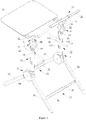
- the child dining chair comprises at least two side supports, a transverse support provided between the side supports and a dining plate 31.
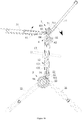
- Each of the side supports comprises a bottom frame, an upright rod assembly 12 and a backrest rod 11, an upper end portion of the bottom frame is roatably connected with a lower end portion of the upright rod assembly 12 via a first rotational joint 5, and an upper end portion of the upright rod assembly 12 is roatably connected with a lower end portion of the backrest rod 11 via a second rotational joint 6.
- the first rotational joints 5 and the second rotational joints 6 are provided with lock mechanisms therein, respectively.
- the dining plate 31 is roatably connected with the upright rod assembles 12 or the backrest rods 11 via the second rotational joints 6; or, the dining plate 31 is roatably connected with the upright rod assembles 12 or the backrest rods 11 via third rotational joints 7.
- the dining plate 31 is roatably connected with the backrest rods 11 via third rotational joints 7, and the third rotational joints 7 are also provided with lock mechanisms therein.
- the first rotational joint 5, the second rotational joint 6 and the third rotational joint 7 are locked by the respective lock mechanisms, and the dining plate 31, the bottom frame, the upright rod assembly 12 and the backrest rod 11 are unfolded with respect to one another; when the child dining chair is in the folded state, the first rotational joint 5, the second rotational joint 6 and the third rotational joint 7 are unlocked, the dining plate 31 and the backrest rod 11 are drawn close to each other, and the bottom frame, the upright rod assembly 12 and the backrest rod 11 are drawn close to one another.
- the bottom frame comprises a front support 15 and a rear support 16 which are capable of being unfolded with respect to each other or being drawn close to each other.
- An upper end portion of the front support 15 and/or an upper end portion of the rear support 16 is rotatably connected with the lower end portion of the upright rod assembly 12 via the first rotational joint 5.
- the upper end portion of the front support 15 and the upper end portion of the rear support 16 are rotatably connected with the lower end portion of the upright rod assembly 12 via one first rotational joint 5.
- the lengths of the upright rod assembly 12, the front support 15 and the rear support 16 are substantially equal, so that the child dining chair has a small size after being folded.
- the upright rod assembly 12 comprises a lower upright rod 121, an upper upright rod 122 slidably connected to the lower upright rod 121 and capable of sliding along an up-down direction, a lower end portion of the lower upright rod 121 is rotatably connected with the front support 15 and the rear support 16 via the first rotational joint 5, and an upper end portion of the upper upright rod 122 is rotatably connected with the lower end portion of the backrest rod 11 via the second rotational joint 6.
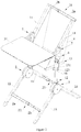
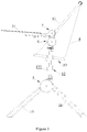
- the upper upright rod 122 is hollow, and the upper upright rod 122 is sleeved on the lower upright rod 121 and capable of sliding along an up-down direction, so that the upright rod assembly 12 may be stretched out and drawn back along the up-down direction, and then the heights of the dining plate 31 and the backrest rod 11, etc. may be adjusted, for example, from a low level as shown in Figure 3 to a high level as shown in Figure 4 .
- Each of the side supports further comprises a seat rod 13 and a connecting rod 14.
- the seat rod 13 substantially extends along a front-rear direction, and the seat rod 13 is rotatably connected to the upper upright rod 122 of the upright rod assembly 12 via a first pivot 91, and the height of the seat rod 13 may be adjusted along with stretching out and drawing back of the upright rod assembly 12.
- the connecting rod 14 substantially extends along an up-down direction, an upper end portion of the connecting rod 14 is roatably connected to the backrest rod 11 or the second rotational joint 6 via a second pivot 92 so that it can be brought to rotate by the backrest rod 11, and a lower end portion of the connecting rod 14 is rotatably connected to the seat rod 13 via a third pivot 93.
- the upright rod assembly 12, the backrest rod 11, the connecting rod 14 and the seat rod 13 form a four-bar linkage capable of being unfolded with respect to one another or being drawn close to one another.
- the upper upright rod 122 has a first connector 123 bending and extending forwards from its main body
- the seat rod 13 has a second connector 131 extending downwards from its main body, and a front end portion of the first connector 123 is rotatably connected with a lower end portion of the second connector 131 via the first pivot 91
- the seat rod 13 has a third connector 132 bending and extending upwards from its main body, and an upper end portion of the third connector 132 is rotatably connected with the lower end portion of the connecting rod 14 via the third pivot 93.
- the third connector 132 is located behind the second connector 131.
- a chair cover 4 is provided between the seat rod 13 and the backrest rod 11 to carry a child, and the dining plate 31 is located in front of the backrest rod 11, and there is a space left between the dining plate 31 and the chair cover 4 for the child in and out.
- the child dining chair further comprises unlock mechanisms capable of unlocking the lock mechanisms within the first rotational joints 5, the lock mechanisms within the second rotational joints 6 and the lock mechanisms within the third rotational joints 7 in a linkage manner, so that when one of the rotational joints is unlocked, the other two rotational joints are unlocked in the linkage manner.
- the present embodiment further specifically provides a first rotational joint 5, a second rotational joint 6, a third rotational joint 7 and an unlock mechanism.
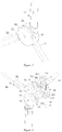
- the first rotational joint 5 comprises a lower upright rod connector 51 fixedly connected with the lower end portion of the lower upright rod 121, a front support connector 52 fixedly connected with the upper end portion of the front support 15, and a rear support connector 53 fixedly connected with the upper end portion of the rear support 16, and the lower upright rod connector 51, the front support connector 52 and the rear support connector 53 are rotatably connected via a fourth pivot 94, so that the three can rotate with respect to one another.
- the first rotational joint 5 further comprises a first locking member 54 movably provided, and outer edges of the lower upright rod connector 51, the front support connector 52 and the rear support connector 53 are respectively provided with slots through which the first locking member 54 is able to insert into, and the first locking member 54 and the three slots form the lock mechanism within the first rotational joint 5.
- the lower upright rod connector 51, the front support connector 52 and the rear support connector 53 are rotated to a position where the slots on them coincide with one another, and at this position, the slots on them coincide to form a first locking slot 501, and the first locking member 54 is inserted into the first locking slot 501 and thus locks the first rotational joint 5; when the child dining chair is in the folded state, the first locking member 54 is disengaged from the slot, and the first rotational joint 5 is unlocked.
- the first locking member 54 is slidably provided within the lower upright rod 121 and capable of sliding along an up-down direction, and thus can disengaged from the first locking slot 501 by moving upward and inserted into the first locking slot 501 by moving downward.
- the lower end portion of the backrest rod 11 is fixedly connected with the backrest rod connector 61, the backrest rod connector 61 serves as one of the component parts of the second rotational joint 6 and the third rotational joint 7, and the second rotational joint 6 is located below the third rotational joint 7.
- the second rotational joint mainly consists of the backrest rod connector 61, a first sliding block 62, a second locking member 63 and an upper upright rod connector 64.
- the upper upright rod connector 64 is fixedly connected with the upper end portion of the upright rod assembly 12 (specifically, the upper upright rod 122), the lower portion of the backrest rod connector 61, the first sliding block 62, the second locking member 63 and the upper upright rod connector 64 are rotatably connected via a fifth pivot 95 successively, and the first sliding block 62 and the second locking member 63 are slidably provided in a space formed between the backrest rod connector 61 and the upper upright rod connector 64 and capable of sliding along an axis line of the fifth pivot 95.
- An outer edge of the second locking member 63 has a plurality of toothed second locking portions 631, and the lower portion of the backrest rod connector 61 is provided with second locking slots 632 cooperating with the second locking portions 631, the upper upright rod connector 64 is also provided with locking slots cooperating with the second locking portions 631, and the second locking portions 631 and the second locking slots 632 on the backrest rod connector 61 and the locking slots on the upper upright rod connector 64 form the lock mechanism within the second rotational joint 6.
- the second locking slots 632 on the backrest rod connector 61 and the locking slots on the upper upright rod connector 64 coincide correspondingly so as to be inserted by the plurality of second locking portions 631, and the backrest rod connector 61 and the upper upright rod connector 64 cannot rotate with respect to each other, thus the second rotational joint 6 is locked;
- the second locking portions 631 are disengaged from the second locking slots 632, the backrest rod connector 61 and the upper upright rod connector 64 can rotate with respect to each other, and the second rotational joint 6 is unlocked.
- the third rotational joint 7 mainly consists of the backrest rod connector 61, a third locking member 71, a second sliding block 72 and a dining plate connector 73.
- the dining plate connector 73 is connected with the dining plate 31, the upper portion of the backrest rod connector 61, the third locking member 71, the second sliding block 72 and the dining plate connector 73 are rotatably connected via a sixth pivot 96 successively.
- the third locking member 71 and the second sliding block 72 are slidably provided in a space formed between the upper portion of the backrest rod connector 61 and the dining plate connector 73 and capable of sliding along an axis line of the sixth pivot 96.
- An outer edge of the third locking member 71 has a plurality of toothed third locking portions 711, and the upper portion of the backrest rod connector 61 is provided with third locking slots 712 cooperating with the third locking portions 711, the dining plate connector 73 is also provided with locking slots cooperating with the third locking portions 711, and the third locking portions 711 and the third locking slots 712 on the backrest rod connector 61 and the locking slots on the dining plate connector 73 form the lock mechanism within the third rotational joint 7.
- the third locking slots 712 on the backrest rod connector 61 and the locking slots on the dining plate connector 73 coincide correspondingly so as to be inserted by the plurality of third locking portions 711, and the backrest rod connector 61 and the dining plate connector 73 cannot rotate with respect to each other, thus the third rotational joint 7 is locked; when the child dining chair is in the folded state, the third locking portions 711 are disengaged from the locking slots on the dining plate connector 73, the backrest rod connector 61 and the dining plate connector 73 can rotate with respect to each other, and the third rotational joint 7 is unlocked.
- the unlock mechanism mainly consists of a handle 81, a first tractive cable (not shown in the figures), a first tractive cable seat 83, a second tractive cable 84, a second tractive cable seat 85 and a third tractive cable (not shown in the figures).
- the handle 81 is provided on the dining plate connector 73 capable of sliding forward and backward; an end of the first tractive cable is fixedly connected to the handle 81, and the other end is fixedly connected to the second sliding block 72; the second sliding block 72 is provided between the dining plate connector 73 and the third locking member 71, one side surface of the dining plate connector 73 has a second guiding bevel in contact and cooperating with the second sliding block 72, and as the second sliding block 72 rotates, under the action of the second guiding bevel, the second sliding block 72 slides along the sixth pivot 96 simultaneously, the third locking member 71 is pushed toward the backrest rod connector 61, until the third locking portions 711 are disengaged from the locking slots on the dining plate connector 73, the third rotational joint 7 is unlocked, the dining plate 31 can be drawn close to the backrest rod; the first tractive cable seat 83 is provided within the third rotational joint 7 and capable of rotating along with the dining plate connector 73, the backrest rod connector 61 has a first mounting groove 831 there
- the following describes the process of unlocking the first rotational joint 5, the second rotational joint 6 and the third rotational joint 7 through the above mentioned unlock mechanism in a linkage manner: pulling the handle 81, the first tractive cable drives the second sliding block 72 to rotate and push the third locking member 71 to slide toward the backrest rod connector 61 until the third locking portions 711 disengage from the locking slots on the dining plate connector 73, the locking effect between the dining plate connector 73 and the backrest rod connector 61 fails, the third rotational joint 7 is unlocked, and the dining plate connector 73 rotates relative to the backrest rod connector 61; the first tractive cable seat 83 rotates along with the dining plate connector 73, and the second tractive cable 84 drives the first sliding block 62 to rotate and pushes the second locking member 63 to slide toward the upper upright rod connector 64 until the second locking portions 631 disengage from the second locking slots 632, the locking effect between the backrest rod connector 61 and the upper upright rod connector 64 fails, the second rotational joint 6 is unlocked, and the backrest rod
- axis lines of the first pivot 91, the second pivot 92, the third pivot 93, the fourth pivot 94, the fifth pivot 95, and the sixth pivot 96 are parallel to one another, and preferably extend along a left-right direction, as shown in Figure 1 .
- the axis lines of the first pivots 91 of the two side supports coincide, the axis lines of the second pivot 92 of the two side supports coincide, the axis lines of the third pivot 93 of the two side supports coincide, the axis lines of the fourth pivot 94 of the two side supports coincide, the axis lines of the fifth pivot 95 of the two side supports coincide, and the axis lines of the sixth pivot 96 of the two side supports coincide, so that the size of the child dining chair in the folded state is further reduced.
- the upper end portion of the connecting rod 14 is rotatably connected with the backrest rod connector 61 of the second rotational joint 6 via the second pivot 92, that is to say, the connecting rod 14 and the backrest rod may be rotatably connected via the backrest rod connector 61 indirectly, and may be rotatably connected directly.
- the fifth pivot 95 is located forward and below the second pivot 92, and the first pivot 91 is located forward and below the third pivot 93.
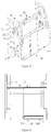
- the transverse support comprises a plurality of transverse rod assemblies capable of being folded or stretched out and drawn back transversely, such as a first transverse rod assembly 21, a second transverse rod assembly 22 and a third transverse rod assembly 23.
- each of the transverse rod assemblies comprises an outer rod 2a and an inner rod 2b slidably connected to the outer rod 2a and capable of sliding along a left-right direction, and one of the outer rod 2a and the inner rod 2b is connected with the left side support and the other is connected with the right side support.
- the outer rod 2a is sleeved on the inner rod 2b and capable of sliding along the left-right direction, thereby capable of being folded transversely along the left-right direction.
- the transverse rod assembles comprise a first transverse rod assembly 21 connected between the backrest rods 11 of the side supports, a second transverse rod assembly 22 connected between the front supports 15 of the side supports, and a third transverse rod assembly 23 connected between the rear supports 16 of the side supports.
- the inner rod 2b is connected with the backrest rod 11 on the left
- the outer rod 2a is connected with the backrest rod 11 on the right
- the outer rod 2a is connected with the front supports 15 on the left
- the inner rod 2b is connected with the front supports 15 on the right
- the inner rod 2b is connected with the rear supports 16 on the left
- the outer rod 2a is connected with the rear supports 16 on the right.
- the lengths of the outer rods 2a of the respective transverse rod assemblies are the same, and the inner rods 2b have the same lengths, and after being folded transversely, the distance between the backrest rods 11 on the two sides, the distance between the front supports 15 on the two sides and the distance between the rear supports 16 on the two sides are the same, the folded child dining chair is neat and has a further reduced size.
- the dining plate 31 is detachably connected with the dining plate connectors 73 of the third rotational joints 7, therefore the dining plate 31 is able to disengage from the dining plate connectors 73 so that the child dining chair may be folded transversely.
- the folding principle of the child dining chair of the present embodiment is as follow: In the unfolded state shown in Figures 1 - 4 , the first rotational joints 5, the second rotational joints 6 and the third rotational joints 7 are locked, the upright rod assembles 12, the backrest rods 11 the connecting rods 14 and the seat rods 13 are unfolded with respect to one another, the front supports 15 and the rear supports 16 are unfolded with respect to each other, and the dining plate 31 is connected to the dining plate connectors 7332 and is substantially horizontal.
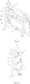
- the dining plate When starting to fold, the handles 81 are pulled to unlock the third rotational joints 7, the second rotational joints 6 and the first rotational joints 5, the dining plate is turned upward and rearward, until it is drawn close to the backrest rods 11, as shown in Figures 5 and 6 ;
- the dining plate 31 and the backrest rods 11 are turned rearward and downward, as the backrest rods 11 are rotated, the connecting rods 14 drives the seat rods 13 to rotate and causes the front end portions of the seat rods 13 to moving upward and the rear end portions to moving downward, until the front end portions of the seat rods 13, the upper end portions of the connecting rods 14 and the upright assembler 12, the lower end portions of the backrest rods 11 are drawn close, and the rear end portions of the seat rods 13, the lower end portions of the connecting rods 14 and the upright assembles 12, the upper end portions of the backrest rods 11 are drawn close, as shown in Figures 7 and 8 ;
- the front supports 5 and the rear supports 16 are turned frontward and upward until the lower end portions thereof
- the child dining chair according to the invention has a small and compact volume after being folded; it can be unlocked by linkage, and is convenient for folding; the height of the dining chair can be adjusted and is convenient to use.
- the dining plate 31 includes a dining plate left portion 311 and a dining plate right portion 312 that are fixedly connected with the dining plate connectors 73 on the two sides, respectively, and the dining plate left portion 311 is slidably connected to the dining plate right portion 312 and capable of sliding in the left-right direction, so that the dining plate left portion 311 and the dining plate right portion 312 can be drawn close to each other, and therefore, when being folded transversely, the transverse folding can be achieved without removing the dining plate 31.
- the dining plate left portion 311 is able to be slidably inserted into the dining plate right portion 312 and capable of sliding in a left-right direction, and when the child dining chair is in the folded state, the dining plate left portion 311 is accepted within the dining plate right portion 312.
Landscapes
- Special Chairs (AREA)
- Table Equipment (AREA)
Applications Claiming Priority (1)
| Application Number | Priority Date | Filing Date | Title |
|---|---|---|---|
| PCT/CN2017/113431 WO2019104493A1 (zh) | 2017-11-28 | 2017-11-28 | 儿童餐椅 |
Publications (2)
| Publication Number | Publication Date |
|---|---|
| EP3677151A1 true EP3677151A1 (de) | 2020-07-08 |
| EP3677151A4 EP3677151A4 (de) | 2020-08-05 |
Family
ID=66665337
Family Applications (1)
| Application Number | Title | Priority Date | Filing Date |
|---|---|---|---|
| EP17933356.2A Withdrawn EP3677151A4 (de) | 2017-11-28 | 2017-11-28 | Essstuhl für kinder |
Country Status (3)
| Country | Link |
|---|---|
| EP (1) | EP3677151A4 (de) |
| JP (1) | JP2021504030A (de) |
| WO (1) | WO2019104493A1 (de) |
Cited By (1)
| Publication number | Priority date | Publication date | Assignee | Title |
|---|---|---|---|---|
| CN113876148A (zh) * | 2021-08-24 | 2022-01-04 | 宁波霍科电器有限公司 | 一种多功能轻薄儿童餐椅 |
Families Citing this family (2)
| Publication number | Priority date | Publication date | Assignee | Title |
|---|---|---|---|---|
| CN111588225B (zh) * | 2020-05-29 | 2024-12-27 | 好孩子儿童用品有限公司 | 儿童餐椅 |
| GB2630108B (en) * | 2023-05-17 | 2025-05-28 | Mamas & Papas Holdings Ltd | A chair for a child |
Family Cites Families (13)
| Publication number | Priority date | Publication date | Assignee | Title |
|---|---|---|---|---|
| US4193630A (en) * | 1978-09-05 | 1980-03-18 | Steele Blake H | Self containing collapsible high chair |
| CN201238864Y (zh) * | 2008-07-14 | 2009-05-20 | 谢明轩 | 一种可调节婴儿高椅 |
| CN202161038U (zh) * | 2011-06-17 | 2012-03-14 | 好孩子儿童用品有限公司 | 儿童餐椅 |
| CN202341489U (zh) | 2011-10-31 | 2012-07-25 | 明门(中国)幼童用品有限公司 | 可折叠儿童餐椅 |
| CN203424653U (zh) * | 2013-07-25 | 2014-02-12 | 中山市隆成日用制品有限公司 | 婴童高脚餐椅收折机构 |
| GB2529055B (en) * | 2014-07-11 | 2017-05-17 | Wonderland Nursery Goods | Seat assembly for an infant chair and infant high chair including the same |
| CN104354750B (zh) * | 2014-10-31 | 2016-07-20 | 广东乐美达集团有限公司 | 一种联动折叠童车的上联动折叠关节 |
| CN204871133U (zh) * | 2015-07-06 | 2015-12-16 | 好孩子儿童用品有限公司 | 儿童推车 |
| CN205513645U (zh) * | 2015-12-25 | 2016-08-31 | 广东乐美达集团有限公司 | 一种联动折叠儿童高餐椅 |
| CN206062693U (zh) * | 2016-06-02 | 2017-04-05 | 好孩子儿童用品有限公司 | 一种儿童餐椅 |
| CN206528508U (zh) * | 2016-10-28 | 2017-09-29 | 慈溪市福贝贝儿童用品有限公司 | 可折叠的婴儿车 |
| CN206615267U (zh) * | 2017-02-24 | 2017-11-07 | 好孩子儿童用品有限公司 | 一种儿童推车 |
| CN107928246A (zh) * | 2017-11-28 | 2018-04-20 | 好孩子儿童用品有限公司 | 儿童餐椅 |
-
2017
- 2017-11-28 EP EP17933356.2A patent/EP3677151A4/de not_active Withdrawn
- 2017-11-28 WO PCT/CN2017/113431 patent/WO2019104493A1/zh not_active Ceased
- 2017-11-28 JP JP2020528897A patent/JP2021504030A/ja active Pending
Cited By (1)
| Publication number | Priority date | Publication date | Assignee | Title |
|---|---|---|---|---|
| CN113876148A (zh) * | 2021-08-24 | 2022-01-04 | 宁波霍科电器有限公司 | 一种多功能轻薄儿童餐椅 |
Also Published As
| Publication number | Publication date |
|---|---|
| JP2021504030A (ja) | 2021-02-15 |
| WO2019104493A1 (zh) | 2019-06-06 |
| EP3677151A4 (de) | 2020-08-05 |
Similar Documents
| Publication | Publication Date | Title |
|---|---|---|
| US10882546B2 (en) | Stroller | |
| EP3552923B1 (de) | Zusammenklappbares kinderwagengestell und zusammenklappbarer kinderwagen | |
| GB2591916A (en) | Folding stroller | |
| CN107685758B (zh) | 儿童推车 | |
| CN104085434B (zh) | 儿童推车的座兜 | |
| CN107928246A (zh) | 儿童餐椅 | |
| EP3677151A1 (de) | Essstuhl für kinder | |
| US10575656B2 (en) | Carrying device and folding method thereof | |
| US20230078130A1 (en) | Folding stroller adaptable for single or double occupants | |
| CN206968751U (zh) | 一种儿童座兜及儿童推车 | |
| CN110979441A (zh) | 一种座椅换向机构及婴儿推车 | |
| CN214524020U (zh) | 一种座位组件及婴儿推车 | |
| CN109466614B (zh) | 一种可折叠推车 | |
| CN208676777U (zh) | 儿童餐椅 | |
| CN212709630U (zh) | 折叠操作简便的座椅及设有该座椅的婴儿车 | |
| CN112092890A (zh) | 一种儿童推车 | |
| CN209454828U (zh) | 儿童推车座椅 | |
| CN109567481B (zh) | 儿童餐椅 | |
| CN209898871U (zh) | 儿童餐椅 | |
| CN211107640U (zh) | 背靠与扶手可联动折叠的座椅及设有该座椅的婴儿车 | |
| CN113386844A (zh) | 一种儿童推车 | |
| CN205632636U (zh) | 一种新型婴儿车骨架 | |
| CN115316817B (zh) | 儿童座兜 | |
| EP3693247A1 (de) | Doppelkinderwagen | |
| CN105438241A (zh) | 一种童车骨架 |
Legal Events
| Date | Code | Title | Description |
|---|---|---|---|
| STAA | Information on the status of an ep patent application or granted ep patent |
Free format text: STATUS: THE INTERNATIONAL PUBLICATION HAS BEEN MADE |
|
| PUAI | Public reference made under article 153(3) epc to a published international application that has entered the european phase |
Free format text: ORIGINAL CODE: 0009012 |
|
| STAA | Information on the status of an ep patent application or granted ep patent |
Free format text: STATUS: REQUEST FOR EXAMINATION WAS MADE |
|
| 17P | Request for examination filed |
Effective date: 20200331 |
|
| AK | Designated contracting states |
Kind code of ref document: A1 Designated state(s): AL AT BE BG CH CY CZ DE DK EE ES FI FR GB GR HR HU IE IS IT LI LT LU LV MC MK MT NL NO PL PT RO RS SE SI SK SM TR |
|
| AX | Request for extension of the european patent |
Extension state: BA ME |
|
| A4 | Supplementary search report drawn up and despatched |
Effective date: 20200702 |
|
| RIC1 | Information provided on ipc code assigned before grant |
Ipc: A47D 1/02 20060101AFI20200626BHEP |
|
| DAV | Request for validation of the european patent (deleted) | ||
| DAX | Request for extension of the european patent (deleted) | ||
| STAA | Information on the status of an ep patent application or granted ep patent |
Free format text: STATUS: EXAMINATION IS IN PROGRESS |
|
| 17Q | First examination report despatched |
Effective date: 20220725 |
|
| GRAP | Despatch of communication of intention to grant a patent |
Free format text: ORIGINAL CODE: EPIDOSNIGR1 |
|
| STAA | Information on the status of an ep patent application or granted ep patent |
Free format text: STATUS: GRANT OF PATENT IS INTENDED |
|
| INTG | Intention to grant announced |
Effective date: 20231130 |
|
| STAA | Information on the status of an ep patent application or granted ep patent |
Free format text: STATUS: THE APPLICATION IS DEEMED TO BE WITHDRAWN |
|
| 18D | Application deemed to be withdrawn |
Effective date: 20240403 |