EP3677320A1 - Übungsunterstützungsprogramm, übungsunterstützungsverfahren und übungsunterstützungssystem - Google Patents
Übungsunterstützungsprogramm, übungsunterstützungsverfahren und übungsunterstützungssystem Download PDFInfo
- Publication number
- EP3677320A1 EP3677320A1 EP17923853.0A EP17923853A EP3677320A1 EP 3677320 A1 EP3677320 A1 EP 3677320A1 EP 17923853 A EP17923853 A EP 17923853A EP 3677320 A1 EP3677320 A1 EP 3677320A1
- Authority
- EP
- European Patent Office
- Prior art keywords
- frames
- frame
- data
- skill
- performance
- Prior art date
- Legal status (The legal status is an assumption and is not a legal conclusion. Google has not performed a legal analysis and makes no representation as to the accuracy of the status listed.)
- Withdrawn
Links
Images







Classifications
-
- G—PHYSICS
- G06—COMPUTING OR CALCULATING; COUNTING
- G06V—IMAGE OR VIDEO RECOGNITION OR UNDERSTANDING
- G06V20/00—Scenes; Scene-specific elements
- G06V20/40—Scenes; Scene-specific elements in video content
-
- A—HUMAN NECESSITIES
- A63—SPORTS; GAMES; AMUSEMENTS
- A63B—APPARATUS FOR PHYSICAL TRAINING, GYMNASTICS, SWIMMING, CLIMBING, OR FENCING; BALL GAMES; TRAINING EQUIPMENT
- A63B69/00—Training appliances or apparatus for special sports
-
- G—PHYSICS
- G06—COMPUTING OR CALCULATING; COUNTING
- G06T—IMAGE DATA PROCESSING OR GENERATION, IN GENERAL
- G06T17/00—Three-dimensional [3D] modelling for computer graphics
-
- G—PHYSICS
- G06—COMPUTING OR CALCULATING; COUNTING
- G06T—IMAGE DATA PROCESSING OR GENERATION, IN GENERAL
- G06T7/00—Image analysis
- G06T7/50—Depth or shape recovery
- G06T7/521—Depth or shape recovery from laser ranging, e.g. using interferometry; from the projection of structured light
-
- G—PHYSICS
- G06—COMPUTING OR CALCULATING; COUNTING
- G06V—IMAGE OR VIDEO RECOGNITION OR UNDERSTANDING
- G06V10/00—Arrangements for image or video recognition or understanding
- G06V10/70—Arrangements for image or video recognition or understanding using pattern recognition or machine learning
- G06V10/74—Image or video pattern matching; Proximity measures in feature spaces
- G06V10/75—Organisation of the matching processes, e.g. simultaneous or sequential comparisons of image or video features; Coarse-fine approaches, e.g. multi-scale approaches; using context analysis; Selection of dictionaries
-
- G—PHYSICS
- G09—EDUCATION; CRYPTOGRAPHY; DISPLAY; ADVERTISING; SEALS
- G09B—EDUCATIONAL OR DEMONSTRATION APPLIANCES; APPLIANCES FOR TEACHING, OR COMMUNICATING WITH, THE BLIND, DEAF OR MUTE; MODELS; PLANETARIA; GLOBES; MAPS; DIAGRAMS
- G09B19/00—Teaching not covered by other main groups of this subclass
- G09B19/003—Repetitive work cycles; Sequence of movements
- G09B19/0038—Sports
-
- G—PHYSICS
- G09—EDUCATION; CRYPTOGRAPHY; DISPLAY; ADVERTISING; SEALS
- G09B—EDUCATIONAL OR DEMONSTRATION APPLIANCES; APPLIANCES FOR TEACHING, OR COMMUNICATING WITH, THE BLIND, DEAF OR MUTE; MODELS; PLANETARIA; GLOBES; MAPS; DIAGRAMS
- G09B5/00—Electrically-operated educational appliances
- G09B5/02—Electrically-operated educational appliances with visual presentation of the material to be studied, e.g. using film strip
-
- G—PHYSICS
- G06—COMPUTING OR CALCULATING; COUNTING
- G06T—IMAGE DATA PROCESSING OR GENERATION, IN GENERAL
- G06T2207/00—Indexing scheme for image analysis or image enhancement
- G06T2207/10—Image acquisition modality
- G06T2207/10016—Video; Image sequence
-
- G—PHYSICS
- G06—COMPUTING OR CALCULATING; COUNTING
- G06T—IMAGE DATA PROCESSING OR GENERATION, IN GENERAL
- G06T2207/00—Indexing scheme for image analysis or image enhancement
- G06T2207/30—Subject of image; Context of image processing
- G06T2207/30196—Human being; Person
-
- G—PHYSICS
- G06—COMPUTING OR CALCULATING; COUNTING
- G06T—IMAGE DATA PROCESSING OR GENERATION, IN GENERAL
- G06T2207/00—Indexing scheme for image analysis or image enhancement
- G06T2207/30—Subject of image; Context of image processing
- G06T2207/30221—Sports video; Sports image
Definitions
- the present invention relates to a practice assist program and the like.
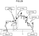
- Performance in gymnastics includes a plurality of scenes constituting a skill.
- FIG. 29 is a diagram for describing an example of scenes constituting a skill.
- FIG. 29 illustrates an example of scenes constituting a skill "triple-twisting Yurchenko layout".
- the skill "triple-twisting Yurchenko layout” includes a phase 1a and a phase 1b.
- the phase 1a includes a scene “take off” and "hand support”.
- the phase 1b includes "flighting", “rotating”, “twisting", and "landing".
- the score of performance is calculated by a total of D (difficulty) score and E (execution) score.
- the D-score is a score calculated depending on the difficulty of a skill constituting the performance.
- the E-score is a score calculated by a point deduction system related to the technique of performance and the posture of the body in each scene of a skill. For example, in the example illustrated in FIG. 29 , at the timing of the scene "hand support", when the body of the player is not straight, the E-score is deducted.
- the purpose of practice of performance is to eliminate the difference between a skill performed by his/herself and a skill indicated in the table of difficulty.
- players shoot their performances by a video camera and compare video of a failed skill and video of a successful skill, and get advices from a coach and repeat practice.
- the above-mentioned conventional technology has a problem in that postures corresponding to a plurality of scenes to be compared are not displayed in a comparative manner.
- the present invention has an object to provide a practice assist program, a practice assist method, and a practice assist system capable of displaying postures corresponding to a plurality of scenes to be compared in a comparative manner.
- a practice assist program for causing a computer to execute processing for: specifying, from first sensing data measured during a performance of a first skill, a plurality of first frames respectively representing a plurality of scenes constituting the first skill; specifying, from second sensing data measured during another performance of the first skill, a plurality of second frames respectively representing the scenes constituting the first skill; and displaying, for at least one of the scenes, the first frames and the second frames in association with each other.
- Postures corresponding to a plurality of scenes can be displayed in a comparable manner.
- FIG. 1 is a diagram illustrating an example of a practice assist system according to a first example.
- the practice assist system includes a three-dimensional (3D) laser sensor 50, a camera 60, a skill recognition device 70, and a practice assist device 100.
- the practice assist device 100 is connected to the 3D laser sensor 50, the camera 60, and the skill recognition device 70.
- the player 10 performs a first skill and then performs the first skill again is described.
- the player 10 is an example of a performer.
- the performance for the first time is referred to as "first performance”
- the performance for the second time is referred to as "second performance”.
- the player 10 performs performances of the same "first skill”.
- the case where the player 10 performs gymnastics performance is described as an example, but the same can be applied to other rating competitions.
- Examples of the other rating competitions include trampolining, diving in swimming, figure skating, Kata in Karate, social dancing, snowboarding, skateboarding, ski aerial, and surfing.
- the present invention may be applied to, for example, checking of the form in classical ballet, ski jumping, air and turns in mogul skiing, baseball, and basketball.
- the present invention may be applied to competitions such as Kendo, Judo, wrestling, and Sumo.
- the 3D laser sensor 50 is a sensor for performing 3D sensing on the player 10.
- the 3D laser sensor 50 outputs sensing data as sensing results to the skill recognition device 70 and the practice assist device 100.
- the 3D laser sensor 50 is an example of a distance image sensor capable of measuring a distance to the player 10.
- FIG. 2 is a diagram for describing sensing data.
- the sensing data includes a plurality of frames, and the frames are given frame numbers for uniquely identifying the frames in an ascending order.
- the sensing data illustrated in FIG. 2 indicates frames having frame numbers n, n+1, ..., n+15, ..., n+30 in the order from older frames.
- n corresponds to a natural number.
- each frame includes distance information from the 3D laser sensor 50 to each point on the player 10.
- the use of the sensing data can estimate the three-dimensional position of each joint of the player 10 in each frame to generate a 3D model of the player 10.
- the time interval from a frame with a frame number n to a frame with a frame number n+1 is 0.33 seconds.
- a frame corresponding to a frame between frames can be generated by interpolation based on preceding and subsequent frames. For example, an n+0.5-th frame can be generated by interpolating a frame having the frame number n and a frame having the frame number n+1.
- the camera 60 is a device for taking video data on the player 10.
- the camera 60 outputs the video data to the practice assist device 100.
- the video data includes a plurality of frames corresponding to an image of the player 10, and each frame is allocated with a frame number.
- FIG. 3 is a diagram for describing the video data.
- the video data illustrated in FIG. 3 indicates frames having frame numbers n, n+1, ... in the order from older frames.
- the frame numbers in the video data and the frame numbers in the sensing data are synchronized with each other.
- the frames included in the sensing data are referred to as "sensing frames” and the frames in the video data are referred to as "video frames" as appropriate.
- the skill recognition device 70 is a device for recognizing phases of a skill and scenes constituting the skill based on sensing data sensed by the 3D laser sensor 50.
- the skill recognition device 70 generates recognition result data in which each frame number of the sensing data is associated with each recognition result.
- the skill recognition device 70 outputs the recognition result data to the practice assist device 100.
- the phase is a unit that sections a skill for descriptive purposes, and a scene is a unit of motion constituting a skill.
- the phase is composed of a plurality of scenes. Depending on events and competitions, the phase is not set, and only the scene indicating a unit of motion is set.
- the skill recognition device 70 compares a skill recognition table (not illustrated) that defines features of skills with sensing data to recognize phases of skills and scenes constituting the skills that correspond to each sensing frame.
- the skill recognition device 70 may use another technology to recognize phases of skills and scenes constituting the skills that correspond to each sensing frame.
- the practice assist device 100 specifies a plurality of first sensing frames corresponding to a plurality of scenes constituting a first skill from sensing data in a first performance.
- the practice assist device 100 specifies a plurality of second sensing frames corresponding to the plurality of scenes constituting the first skill from sensing data in a second performance.
- the practice assist device 100 displays, for each of the scenes, the first sensing frames and the second sensing frames in association with each other in chronological order.
- the practice assist device 100 estimates joint positions and skeleton positions of the player 10 based on the sensing data, and generates 3D model data on the player 10.
- the practice assist device 100 displays three-dimensional models corresponding to first sensing frames and three-dimensional models corresponding to second sensing frames in association with each other.
- FIG. 4 is a diagram (1) illustrating an example of a display screen displayed by the practice assist device according to the first example.
- a display screen 80 includes a display region 80a and a display region 80b.
- the first skill includes a first scene, a second scene, an m-th scene, and an (m+n)-th scene.
- the display region 80a a 3D model of a first sensing frame corresponding to the m-th scene is displayed.
- the display region 80b a 3D model of a second sensing frame corresponding to the m-th scene is displayed.
- the practice assist device 100 displays the scene of the skill corresponding to the 3D model displayed in the display region 80a and the scene of the skill of the 3D model displayed in the display region 80b in synchronization with each other.
- the practice assist device 100 displays the display screen 80 as illustrated in FIG. 4 , so that the postures of the player 10 corresponding to a plurality of scenes to be compared can be displayed in a comparative manner.
- FIG. 5 is a functional block diagram illustrating the configuration of the practice assist device according to the first example.
- the practice assist device 100 includes an interface unit 110, a communication unit 120, an input unit 130, a display unit 140, a storage unit 150, and a control unit 160.
- the display unit 140 and an output unit 165 are examples of a display unit.
- the interface unit 110 is a device connected to the 3D laser sensor 50, the camera 60, and the skill recognition device 70 to acquire data from the 3D laser sensor 50, the camera 60, and the skill recognition device 70.
- the interface unit 110 outputs the acquired data to the control unit 160.
- the interface unit 110 acquires sensing data from the 3D laser sensor 50.
- the interface unit 110 acquires video data from the camera 60.
- the interface unit 110 acquires recognition result data from the skill recognition device 70.
- the communication unit 120 is a device for communicating data to other devices through a network.
- the communication unit 120 corresponds to a communication device.
- the practice assist device 100 may be connected to the 3D laser sensor 50, the camera 60, and the skill recognition device 70 through the network.
- the communication unit 120 acquires data from the 3D laser sensor 50, the camera 60, and the skill recognition device 70 through the network.
- the input unit 130 is an input device for inputting various kinds of information to the practice assist device 100.
- the input unit 130 corresponds to a keyboard, a mouse, or a touch panel, for example.
- a user operates the input unit 130 to designate sensing data in a first performance and sensing data in a second performance.
- the user operates the input unit 130 to designate a scene to be referred to among a plurality of scenes constituting a skill.
- the user may be a player 10, or may be another user such as a coach.
- the display unit 140 is a display device for displaying information on a display screen output from the control unit 160.
- the display unit 140 displays the display screen 80 described above with reference to FIG. 4 .
- the display unit 140 corresponds to a liquid crystal display or a touch panel, for example.
- the storage unit 150 has a sensing database (DB) 151, a skill recognition DB 152, a video DB 153, joint definition data 154, a joint position DB 155, and a 3D model DB 156.
- the storage unit 150 corresponds to a storage device such as a semiconductor memory element represented by a random access memory (RAM), a read only memory (ROM), and a flash memory, and a hard disk drive (HDD).
- RAM random access memory
- ROM read only memory
- HDD hard disk drive
- the sensing DB 151 is a database for storing therein sensing data from the 3D laser sensor 50.
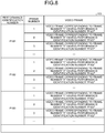
- FIG. 6 is a diagram illustrating an example of the data structure of the sensing DB according to the first example. As illustrated in FIG. 6 , the sensing DB 151 associates a performance identification number, a frame number, and a sensing frame with one another.
- the performance identification number is a number for uniquely identifying a performance performed separately. Even the same performance is given a different performance identification number when a timing of being sensed by the 3D laser sensor 50 is different. For example, a first performance and a second performance are allocated with different performance identification numbers.
- the frame number is a number for uniquely identifying each sensing frame corresponding to the same performance identification number.
- the sensing frame is a sensing frame sensed by the 3D laser sensor 50.
- the skill recognition DB 152 is a database for storing therein recognition result data acquired from the skill recognition device 70.
- FIG. 7 is a diagram illustrating an example of the data structure of the skill recognition DB according to the first example. As illustrated in FIG. 7 , the skill recognition DB 152 associates a performance identification number, a frame number, and skill recognition result data with one another. The description on the performance identification number is the same as the description for the sensing DB 151.
- the frame number is a number for uniquely identifying each sensing frame corresponding to the same performance identification number.
- the frame number in FIG. 7 and the frame number in FIG. 6 are synchronized with each other.
- a scene representing a skill among scenes constituting the skill is set as an example.
- the frame is a frame corresponding to "scene A” constituting the skill
- the frame is not a frame corresponding to a scene constituting the skill
- the video DB 153 is a database for storing therein video data acquired from the camera 60.
- FIG. 8 is a diagram illustrating an example of the data structure of the video DB according to the first example. As illustrated in FIG. 8 , the video DB 153 associates a performance identification number, a frame number, and a video frame with one another. The description on the performance identification number is the same as that for the sensing DB 151.
- the frame number is a number for uniquely identifying each video frame corresponding to the same performance identification number.
- the frame number of a video frame is synchronized with the frame number of a sensing frame.
- the video frame is a video frame taken by the camera 60.
- the joint definition data 154 defines each joint position of a performer (player 10).
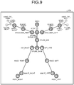
- FIG. 9 is a diagram illustrating an example of the joint definition data according to the first example.
- the joint definition data 154 stores therein information in which joints specified by a publicly known skeleton model are numbered. For example, as illustrated in FIG. 9 , a right shoulder joint (SHOULDER_RIGHT) is given 7, a left elbow joint (ELBOW_LEFT) is given 5, a left knee joint (KNEE_LEFT) is given 11, and a right hip joint (HIP_RIGHT) is given 14.
- SHOULDER_RIGHT right shoulder joint
- ELBOW_LEFT left elbow joint
- KNEE_LEFT left knee joint
- HIP_RIGHT right hip joint
- the X coordinate, the Y coordinate, and the Z coordinate of the right shoulder joint 8 are sometimes referred to as "X8", “Y8", and “Z8", respectively.
- Dotted numerals are joints and the like that are specified from the skeleton model but not used for rating.
- the joint position data 154 is position data on each joint of the player 10 generated based on the sensing data of the 3D laser sensor 50.
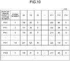
- FIG. 10 is a diagram illustrating an example of the data structure of the joint position DB according to the first example. As illustrated in FIG. 10 , the joint position DB 155 associates a performance identification number, a frame number, and "X0, Y0, Z0, ..., X17, Y17, and Z17" with one another. The description on the performance identification number is the same as that for the sensing DB 151.
- the frame number is a number for uniquely identifying each sensing frame corresponding to the same performance identification number.
- the frame number illustrated in FIG. 10 and the frame number illustrated in FIG. 6 are synchronized with each other.
- "X0, Y0, Z0, ..., X17, Y17, and Z17” are XYZ coordinates of the joints.
- "X0, Y0, and Z0" are three-dimensional coordinates of the joint with the number 0 illustrated in FIG. 9 .
- the 3D model DB 156 is a database for storing therein information on a 3D model of the player 10 generated based on sensing data.
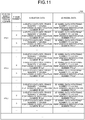
- FIG. 11 is a diagram illustrating an example of the data structure of the 3D model DB according to the first example. As illustrated in FIG. 11 , the 3D model DB 156 associates a performance identification number, a frame number, skeleton data, and 3D model data with one another. The descriptions on the performance identification number and the frame number are the same as those for the sensing DB 151.
- the skeleton data is data indicating a skeleton of the player 10 estimated by connecting joint positions.
- the 3D model data is data on a 3D model of the player 10 estimated based on information obtained from the sensing data and the skeleton data.
- control unit 160 includes a registration unit 161, a 3D model generation unit 162, a reception unit 163, a specifying unit 164, and an output unit 165.
- the control unit 160 can be implemented by a central processing unit (CPU) or a micro processing unit (MPU).
- the control unit 160 can also be implemented by hardware wired logic such as an application specific integrated circuit (ASIC) and a field programmable gate array (FPGA).
- ASIC application specific integrated circuit
- FPGA field programmable gate array
- the registration unit 161 acquires sensing data from the 3D laser sensor 50, and registers the acquired sensing data in the sensing DB 151.
- the registration unit 161 registers the sensing data (frame number, sensing frame) in the sensing DB 151 in association with a performance identification number.
- the performance identification number is designated by a user through the input unit 130 and the like.
- the registration unit 161 acquires recognition result data from the skill recognition device 70, and registers the acquired recognition result data in the skill recognition DB 152.
- the registration unit 161 registers the skill recognition result data (frame number, skill recognition result data) in the skill recognition DB 152 in association with a performance identification number.
- the performance identification number is designated by the user through the input unit 130 and the like.
- the registration unit 161 acquires video data from the camera 60, and registers the acquired video data in the video DB 153.
- the registration unit 161 registers the video data (frame number, video frame) in the video DB 153 in association with a performance identification number.
- the performance identification number is designated by the user through the input unit 130 and the like.
- the 3D model generation unit 162 is a processing unit for generating 3D model data corresponding to each frame number having each performance identification number based on the sensing DB 151. In the following, an example of processing of the 3D model generation unit 162 is described.
- the 3D model generation unit 162 compares sensing frames in the sensing DB 151 with the positional relation of joints defined in the joint definition data 154 to specify the types of joints included in the sensing frames and three-dimensional coordinates of the joints.
- the 3D model generation unit 162 repeatedly executes the above-mentioned processing for each frame number having each performance identification number to generate the joint position DB 155.
- the 3D model generation unit 162 connects the three-dimensional coordinates of the joints stored in the joint position DB 155 based on the connection relation defined in the joint definition data 154 to generate skeleton data.
- the 3D model generation unit 162 fits the estimated skeleton data to a skeleton model adjusted to the physical size of the player 10 to generate 3D model data.
- the 3D model generation unit 162 repeatedly executes the above-mentioned processing for each frame number having each performance identification number to generate the 3D model DB 156.
- the reception unit 163 is a processing unit for receiving, from the input unit 130 and the like, two types of performance identification numbers corresponding to two performances to be compared by the user.
- the reception unit 163 outputs information on the received two types of performance identification numbers to the specifying unit 164.
- first performance two performances to be compared by the user are referred to as "first performance” and "second performance”.
- the performance identification number corresponding to the first performance is referred to as "first performance identification number”
- the performance identification number corresponding to the second performance is referred to as "second performance identification number”.
- the relation between the first performance and the second performance corresponds to a performance before coaching and a performance after coaching.
- the relation between the first performance and the second performance corresponds to a failed performance and a successful performance.
- the relation between the first performance and the second performance may be simply a performance in the past and the latest performance. Performers (players 10) of the first performance and the second performance may be the same person or different persons.
- the reception unit 163 receives information on additional display locations.
- the information on additional display locations includes information for identifying a scene in a skill and a plurality of joints that are desired by a user.
- the reception unit 163 outputs information on the additional display locations to the output unit 165.
- the reception unit 163 displays an additional display location selection screen for selecting an additional display location on the display unit 140, and receives information on the additional display location.
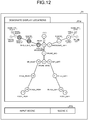
- FIG. 12 is a diagram illustrating an example of the additional display location selection screen according to the first example.
- an additional display location selection screen 81 has a selection form 81a for selecting joints as display locations, and an input form 81b for inputting a scene.
- the user operates the input unit 130 to input information on additional display locations.
- joints 7, 8, and 9 are selected as additional display locations, and a scene E is input.
- a skill may be designated and a specific scene E may be selected from among scenes constituting the designated skill.
- the reception unit 163 receives, from the input unit 130 and the like, information on the position and direction of a virtual line-of-sight when referring to the 3D model.
- the information on the position and direction of the virtual line-of-sight is referred to as "virtual line-of-sight data”.
- the reception unit 163 outputs the virtual line-of-sight data to the output unit 165.
- the specifying unit 164 acquires the first performance identification number and the second performance identification number from the reception unit 163.
- the specifying unit 164 refers to the skill recognition DB 152 for skill recognition result data having each frame number corresponding to the first performance identification number, and specifies frame numbers (hereinafter referred to as "first frame numbers") respectively representing a plurality of scenes constituting a skill in the first performance.
- the specifying unit 164 outputs the first performance identification number and the specified first frame numbers to the output unit 165.
- the frame is a frame representing the scene.
- a predetermined frame is a frame representing the scene. Examples of the predetermined frame include the first frame, a middle frame, and the last frame among a plurality of frames constituting a scene.
- the specifying unit 164 refers to the skill recognition DB 152 for skill recognition result data having each frame number corresponding to the second performance identification number, and specifies frame numbers (hereinafter referred to as "second frame numbers") respectively representing the scenes constituting the skill in the second performance.
- the specifying unit 164 outputs the second performance identification number and the specified second frame numbers to the output unit 165.
- a plurality of sensing frames corresponding to the first frame numbers having the first performance identification number are referred to as a plurality of "first sensing frames”.
- a plurality of sensing frames corresponding to the second frame numbers having the second performance identification number are referred to as a plurality of "second sensing frames”.
- the output unit 165 is a processing unit for displaying, for each of a plurality of scenes, the first sensing frames and the second sensing frames in association with each other in chronological order on the display unit 140. Examples of processing 1 to 5 by the output unit 165 are described below.
- Processing 1 executed by the output unit 165 is described.
- the processing 1 by the output unit 165 is processing for generating information on the display screen 80 described above with reference to FIG. 4 and outputting the generated information to the display unit 140.
- scenes constituting a first performance and a second performance include "scene A, scene B, scene C, ##.
- the output unit 165 uses a frame number of a first sensing frame corresponding to the scene A among a plurality of first sensing frames as a key to detect corresponding first 3D model data from the 3D model DB 156.
- the output unit 165 generates an image of the first 3D model data seen from a virtual line-of-sight with reference to virtual line-of-sight data, and places the image in the display region 80a.
- the output unit 165 uses a frame number of a second sensing frame corresponding to the scene A among a plurality of second sensing frames as a key to detect corresponding second 3D model data from the 3D model DB 156.
- the output unit 165 generates an image of the second 3D model data seen from the virtual line-of-sight with reference to the virtual line-of-sight data, and places the image in the display region 80b.
- the output unit 165 repeats the above-mentioned processing for the other scenes "scene B, scene C, ", so that first 3D model data corresponding to "scene B, scene C, " is displayed in the display region 80a.
- first 3D model data corresponding to "scene B, scene C, " is displayed in the display region 80a.
- second 3D model data corresponding to "scene B, scene C, " is displayed.
- the output unit 165 synchronizes the scene in the first 3D model data displayed in the display region 80a and the scene in the second 3D model data displayed in the display region 80b.
- the practice assist device 100 displays the display screen 80 as illustrated in FIG. 4 , so that the postures of the player 10 corresponding to scenes to be compared can be displayed in a comparative manner.
- FIG. 13 is a diagram (2) illustrating an example of the display screen displayed by the practice assist device according to the first example.
- the output unit 165 generates an image of first 3D model data and an image of second 3D model data.
- the output unit 165 displays the image of the first model data and the image of the second 3D model data in a display region 82a in a superimposed manner.
- the scene in the first 3D model data and the scene in the second 3D model data displayed in the display region 82a are the same.
- first 3D model data and second 3D model data corresponding to a scene in a phase are displayed in the display region 82a in a superimposed manner.
- set line-of-sight data virtual line-of-sight data (hereinafter referred to as "set line-of-sight data") from which the posture of the player 10 is easily grasped is set in advance for each scene.
- the output unit 165 generates images in display regions 82b and 82c based on set line-of-sight data corresponding to a scene in the first 3D model data and the second 3D model data currently displayed in the display region 82a.
- the output unit 165 generates an image of the first 3D model data seen from a virtual line-of-sight with reference to the set line-of-sight data, and sets the image in the display region 82b.
- the output unit 165 may additionally display an angle between a straight line 82d passing through a predetermined joint in the 3D model data and a horizontal line 82e.
- the output unit 165 generates an image of the second 3D model data seen from the virtual line-of-sight with reference to the set line-of-sight data, and sets the image in the display region 82c.
- the output unit 165 may additionally display an angle between a straight line 82f passing through a predetermined joint in the 3D model data and a horizontal line 82g.
- the practice assist device 100 displays the display screen 82 as illustrated in FIG. 13 , so that the postures of the player 10 corresponding to scenes to be compared can be displayed in a comparative manner.
- Video of 3D models related to a first performance and a second performance seen from virtual lines-of-sight can be simultaneously referred to for each scene.
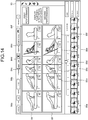
- FIG. 14 is a diagram (3) illustrating an example of the display screen displayed by the practice assist device according to the first example.
- the output unit 165 specifies each piece of first 3D model data corresponding to each scene and each piece of second 3D model data corresponding to each scene.
- the output unit 165 generates images 84a to 84f of first 3D model data of scenes A to F seen from a virtual line-of-sight with reference to virtual line-of-sight data, and places the images in a display region 84 in chronological order.
- Numerals indicated by the images 84a to 84f indicate frame numbers. For example, the frame number of the image 84a corresponding to the scene A is "40".
- the output unit 165 generates images 85a to 85f of second 3D model data of the scenes A to F seen from the virtual line-of-sight with reference to the virtual line-of-sight data, and places the images in a display region 85 in chronological order.
- Numerals indicated by the images 85a to 85f indicate frame numbers. For example, the frame number of the image 85a corresponding to the scene A is "50".
- the output unit 165 arranges the images 84a to 84f in the display region 84 and arranges the images 85a to 85f in the display region 85, the output unit 165 arranges the images such that scenes of the upper and lower images are the same.
- the practice assist device 100 displays the display screen 83 as illustrated in FIG. 14 , so that the postures of the player 10 corresponding to scenes to be compared can be displayed in chronological order in a comparative manner.
- a user can grasp a time taken between a scene and a subsequent scene in a first performance and a time taken between a scene and a subsequent scene in a second performance.
- the user can grasp that a time taken for shifting from a scene to a subsequent scene in a second performance is shorter or longer than that in a first performance, and can practice while being aware of speed of the performance.
- FIG. 15 is a diagram (4) illustrating an example of the display screen displayed by the practice assist device according to the first example.
- the output unit 165 generates images 87a to 87f of first 3D model data of scenes A to F seen from a virtual line-of-sight with reference to virtual line-of-sight data, and places the images in a display region 87 in chronological order.
- the output unit 165 generates images 88a to 88f of first 3D model data of the scenes A to F seen from the virtual line-of-sight with reference to the virtual line-of-sight data, and places the images in a display region 88 in chronological order.
- the output unit 165 acquires information on additional display locations from the reception unit 163.
- the information on additional display locations includes the joints 7, 8, and 9 and the scene E.
- the output unit 165 specifies the positions of the joints 7, 8, and 9 based on the frame number of a first sensing frame corresponding to the scene E among a plurality of first sensing frame and based on the joint position DB 155.
- the output unit 165 displays a line segment 89a passing through the joint positions 7, 8, and 9 on an image 87e corresponding to the scene E.
- the output unit 165 specifies the positions of the joints 7, 8, and 9 based on the frame number of a second sensing frame corresponding to the scene E among a plurality of second sensing frames and based on the joint position DB 155.
- the output unit 165 displays a line segment 89b passing through the joint positions 7, 8, and 9 on an image 88e corresponding to the scene E.
- the output unit 165 may display the line segment 89a and the line segment 89b on the image 88e in a superimposed manner.
- the practice assist device 100 displays the display screen 86 as illustrated in FIG. 15 on the display unit 140, so that a change (degree of improvement) in joint position related to an additional display location can be easily grasped.
- a change degree of improvement
- performances for example, first performance and second performance
- performances for example, first performance and second performance
- the user can easily compare performances before and after coaching from an easy-to-view direction in regard to the area near the wrist.
- sensing data measured by the 3D laser sensor 50 used in the practice assist device 100 has 3D information.
- 3D model data seen from the designated virtual line-of-sight can be generated to display the postures in scenes in a comparative manner.
- FIG. 16 is a diagram (5) illustrating an example of the display screen displayed by the practice assist device according to the first example.
- the output unit 165 generates images 91a, 91b, and 91c of first 3D model data of scenes A, B, and C seen from a virtual line-of-sight with reference to virtual line-of-sight data, and places the images in a display region 91 in chronological order.
- the output unit 165 generates images 92a, 92b, and 92c of second 3D model data of the scenes A, B, and C seen from the virtual line-of-sight with reference to the virtual line-of-sight data, and places the images in a display region 92 in chronological order.
- the output unit 165 displays a time interval based on the number of frames between scenes in such a manner that the time interval can be grasped. For example, the output unit 165 displays a "rectangle" every 10 frames based on the number of frames between scenes.
- the output unit 165 compares the frame number of a sensing frame corresponding to each scene with the sensing DB 151 to calculate the number of frames between scenes.
- the output unit 165 displays two "rectangles" between the image 91a and the image 91b.
- the output unit 165 displays three "rectangles" between the image 91b and the image 91c.
- the output unit 165 displays one "rectangle" between the image 92a and the image 92b.
- the output unit 165 displays two "rectangles" between the image 92b and the image 92c.
- the practice assist device 100 displays the display screen 90 as illustrated in FIG. 16 on the display unit 140, so that the user can easily visually grasp the number of frames between scenes.
- the user can easily grasp performance speed of a skill performed by the player 10, and compare a timing difference. For example, when the first performance and the second performance are compared, the number of rectangles in the first performance between images is larger than the number of rectangles in the second performance, and hence the fact that the timing of the second performance is faster than that of the first performance can be easily grasped.
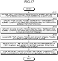
- FIG. 17 is a flowchart (1) illustrating a processing procedure of the practice assist device according to the first example.
- the reception unit 163 in the practice assist device 100 receives a first performance identification number and a second performance identification number to be compared (Step S101).
- the specifying unit 164 in the practice assist device 100 specifies a plurality of first sensing frames respectively representing a plurality of scenes constituting a first skill from sensing data measured during a first performance (during first performance corresponding to first performance identification number) (Step S102).
- the specifying unit 164 specifies a plurality of second sensing frames respectively representing the scenes constituting the first skill from sensing data measured during a second performance (during second performance corresponding to second performance identification number) (Step S103) .
- the output unit 165 in the practice assist device 100 associates the first sensing frames and the second sensing frames for each of the scenes (Step S104).
- the reception unit 163 receives virtual line-of-sight data, and the output unit 165 generates images of a first 3D model and images of a second 3D model seen from a virtual line-of-sight (Step S105).
- the output unit 165 displays the images of the first 3D model and the images of the second 3D model in association with each other in chronological order (Step S106).
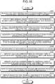
- FIG. 18 is a flowchart (2) illustrating a processing procedure of the practice assist device according to the first example. As illustrated in FIG. 18 , the reception unit 163 in the practice assist device 100 receives a first performance identification number and a second performance identification number to be compared (Step S201).
- the specifying unit 164 in the practice assist device 100 specifies a plurality of first sensing frames respectively representing a plurality of scenes constituting a first skill from sensing data measured during a first performance (during first performance corresponding to first performance identification number) (Step S202).
- the specifying unit 164 specifies a plurality of second sensing frames respectively representing the scenes constituting the first skill from sensing data measured during a second performance (during second performance corresponding to second performance identification number) (Step S203).
- the output unit 165 in the practice assist device 100 associates the first sensing frames and the second sensing frames for each of the scenes (Step S204).
- the reception unit 163 receives virtual line-of-sight data, and the output unit 165 generates images of a first 3D model and images of a second 3D model seen from a virtual line-of-sight (Step S205).
- the reception unit 163 receives input of information on additional display locations (Step S206).
- the output unit 165 specifies locations in the first sensing frames that correspond to the additional display locations, and displays a first line segment on the image of the first 3D model (Step S207). For example, the first line segment corresponds to the line segment 89a in FIG. 15 .
- the output unit 165 specifies locations in the second sensing frames that correspond to the additional display locations, and displays a second line segment on the image of the second 3D model (Step S208).
- the second line segment corresponds to the line segment 89b in FIG. 15 .
- the output unit 165 displays the first line segment and the second line segment on the image of the second 3D model in a superimposed manner (Step S209).
- the output unit 165 displays the images of the first 3D model and the images of the second 3D model in association with each other in chronological order (Step S210).
- FIG. 19 is a flowchart (3) illustrating a processing procedure of the practice assist device according to the first example. As illustrated in FIG. 19 , the reception unit 163 in the practice assist device 100 receives a first performance identification number and a second performance identification number to be compared (Step S301).
- the specifying unit 164 in the practice assist device 100 specifies a plurality of first sensing frames respectively representing a plurality of scenes constituting a first skill from sensing data measured during a first performance (during first performance corresponding to first performance identification number) (Step S302).
- the specifying unit 164 specifies a plurality of second sensing frames respectively representing the scenes constituting the first skill from sensing data measured during a second performance (during second performance corresponding to second performance identification number) (Step S303).
- the output unit 165 in the practice assist device 100 associates the first sensing frames and the second sensing frames for each of the scenes (Step S304).
- the reception unit 163 receives virtual line-of-sight data, and the output unit 165 generates images of a first 3D model and images of a second 3D model seen from a virtual line-of-sight (Step S305).
- the output unit 165 displays the images of the first 3D model and the images of the second 3D model in association with each other in chronological order (Step S306).
- the output unit 165 calculates the numbers of frames between scenes in the first performance and the second performance (Step S307).
- the output unit 165 calculates the number of rectangles in accordance with the number of frames between scenes (Step S308).
- the output unit 165 displays a figure corresponding to the number of rectangles between the scenes (Step S309).
- the practice assist device 100 specifies first sensing frames corresponding to scenes constituting a first skill from sensing data measured during a first performance.
- the practice assist device 100 specifies second sensing frames corresponding to the scenes constituting the first skill from sensing data measured during a second performance.
- the practice assist device 100 displays, for each of the scenes, the first sensing frames and the second sensing frames in association with each other in chronological order. In this manner, the practice assist device 100 can display the postures of the player 10 corresponding to a plurality of scenes to be compared in a comparative manner.
- the output unit 165 may perform the following processing.
- the output unit 165 may synchronize the frame numbers of sensing frames displayed on the display screens 80 and 82 to 90, and display video frames in the video DB 153 in predetermined regions on the display screens 80 and 82 to 90.
- FIG. 20 is a diagram illustrating an example of a practice assist system according to a second example.
- the practice assist system includes a 3D laser sensor 50, a camera 60, a skill recognition device 70, and a practice assist device 200.
- the descriptions on the 3D laser sensor 50, the camera 60, and the skill recognition device 70 are the same as those with reference to FIG. 1 .
- the case where a player 10 performs a performance of a first skill and thereafter performs a performance of the first skill again is described as an example.
- a performance for the first time is referred to as "first performance”
- a performance for the second time is referred to as "second performance”.
- the player 10 performs performances of the same first skill.
- the case where the player 10 performs gymnastics performance is described as an example, but the same can be applied to other rating competitions (such as figure skating).
- the practice assist device 200 compares a transition of first skeleton data corresponding to first sensing data and a transition of second skeleton data corresponding to second sensing data to specify a scene in which a difference between the transition of first skeleton data and the transition of second skeleton data is equal to or more than a predetermined value among a plurality of scenes.
- the scene in which the difference is equal to or more than the predetermined value corresponds to a scene in which the player 10 has failed a skill among scenes.
- the practice assist device 200 generates and displays a display screen in such a manner that the timing of the specified scene can be grasped.
- FIG. 21 is a diagram illustrating an example of a display screen displayed by the practice assist device according to the second example.
- a display screen 93 includes a display region 93a, a display region 93b, and a display region 93c.
- a first skill includes a first scene, a second scene, ..., and an m-th scene.
- the frame numbers of sensing frames corresponding to the first scene to the m-th scene are frame numbers 1 to m.
- 3D models images of 3D model data seen from virtual line-of-sight
- 3D models of second sensing frames corresponding to the first scene to the m-th scene are displayed.
- scenes in which a difference between a transition of first skeleton data and a transition of second skeleton data is equal to or more than a threshold are scenes having frame numbers 8 to 12 (eighth scene to twelfth scene).
- the practice assist device 200 displays images of the 3D model with the frame numbers 8 to 12 in the display region 93a in an emphasized manner.
- the transition of first skeleton data and the transition of second skeleton data are displayed as a graph.
- the transition of skeleton data is swing speed of the right ankle of the player 10.
- the horizontal axis of the graph in the display region 93c corresponds to the frame number, and the vertical axis corresponds to the swing speed of the right ankle of the player 10.
- a line segment 94a is a line segment indicating a relation between the swing speed of the right ankle of the player 10 and the frame number corresponds to first skeleton data.
- a line segment 94b is a line segment indicating a relation between the swing speed of the right ankle of the player 10 and the frame number corresponding to second skeleton data. Compared with the line segment 94b, the line segment 94a indicates that the difference in speed becomes equal to or more than a threshold after the frame number 8, and the player 10 has failed the first performance.
- the practice assist device 200 displays the display screen 93 illustrated in FIG. 21 , so that the user can easily compare an image of the 3D model that has the failed skill and an image of the 3D model that has the successful skill. By displaying an image in an emphasized manner, the user can easily refer to an image of a 3D model in a failed scene among a plurality of scenes constituting the first skill.
- FIG. 22 is a functional block diagram illustrating the configuration of the practice assist device according to the second example.
- the practice assist device 200 includes an interface unit 210, a communication unit 220, an input unit 230, a display unit 240, a storage unit 250, and a control unit 260.
- the descriptions on the interface unit 210, the communication unit 220, the input unit 230, and the display unit 240 are the same as the above descriptions on the interface unit 110, the communication unit 120, the input unit 130, and the display unit 140 with reference to FIG. 5 .
- the storage unit 250 has a sensing DB 251, a skill recognition DB 252, a video DB 253, joint definition data 254, a joint position DB 255, and a 3D model DB 256.
- the storage unit 250 corresponds to a storage device such as a semiconductor memory element represented by a RAM, a ROM, and a flash memory, and an HDD.
- sensing DB 251, the skill recognition DB 252, the video DB 253, the joint definition data 254, the joint position DB 255, and the 3D model DB 256 are the same as the above descriptions on the sensing database (DB) 151, the skill recognition DB 152, the video DB 153, the joint definition data 154, the joint position DB 155, and the 3D model DB 156 with reference to FIG. 5 .
- the control unit 260 includes a registration unit 261, a 3D model generation unit 262, a reception unit 263, a specifying unit 264, and an output unit 265.
- the control unit 260 can be implemented by a CPU or an MPU.
- the control unit 260 can also be implemented by hard wired logic such as an ASIC.
- the registration unit 261 acquires sensing data from the 3D laser sensor 50, and registers the acquired sensing data in the sensing DB 251.
- the registration unit 261 registers the sensing data (frame number, sensing frame) in the sensing DB 251 in association with a performance identification number.
- the performance identification number is designated by a user through the input unit 230 and the like.
- the performance identification number is data for uniquely identifying a performance performed by a player 10.
- the registration unit 261 acquires recognition result data from the skill recognition device 70, and registers the acquired recognition result data in the skill recognition DB 252.
- the registration unit 261 registers the skill recognition result data (frame number, skill recognition result data) in the skill recognition DB 252 in association with a performance identification number.
- the performance identification number is designated by the user through the input unit 230 and the like.
- the registration unit 261 acquires video data from the camera 60, and registers the acquired video data in the video DB 253.
- the registration unit 261 registers the video data (frame number, video frame) in the video DB 253 in association with a performance identification number.
- the performance identification number is designated by the user through the input unit 230 and the like.
- the 3D model generation unit 262 is a processing unit for generating 3D model data corresponding to each frame number having each performance identification number based on the sensing DB 251.
- the 3D model generation unit 262 registers the generated 3D model data in the 3D model DB 256.
- the processing for generating 3D model data by the 3D model generation unit 262 is the same as the processing by the 3D model generation unit 162 illustrated in FIG. 5 .
- the reception unit 263 is a processing unit for receiving, from the input unit 230 and the like, two kinds of performance identification numbers corresponding to two performances to be compared by the user.
- the reception unit 263 outputs information on the received two kinds of performance identification numbers to the specifying unit 264.
- first performance two performances to be compared by the user are referred to as "first performance” and "second performance”.
- the performance identification number corresponding to the first performance is referred to as "first performance identification number”
- the performance identification number corresponding to the second performance is referred to as "second performance identification number”.
- the specifying unit 264 acquires a first performance identification number and a second performance identification number from the reception unit 263.
- the specifying unit 264 refers to the skill recognition DB 252 for skill recognition result data having each frame number corresponding to the first performance identification number, and specifies frame numbers (hereinafter referred to as "first frame numbers") respectively representing a plurality of scenes constituting a skill (first skill) in the first performance.
- the specifying unit 264 outputs the first performance identification number and the specified first frame numbers to the output unit 265.
- the specifying unit 264 refers to the skill recognition DB 252 for skill recognition result data having each frame number corresponding to the second performance identification number, and specifies frame numbers (hereinafter referred to as "second frame numbers") respectively representing the scenes constituting the skill (first skill) in the second performance.
- the specifying unit 264 outputs the second performance identification number and the specified second frame numbers to the output unit 265.
- a plurality of sensing frames corresponding to the first frame numbers having the first performance identification number are referred to as a plurality of "first sensing frames”.
- a plurality of sensing frames corresponding to the second frame numbers having the second performance identification number are referred to as a plurality of "second sensing frames”.
- the specifying unit 264 acquires each piece of skeleton data (first skeleton data) corresponding to each of the specified first frame numbers from the 3D model DB 256.
- the specifying unit 264 calculates a transition of the first skeleton data every predetermined number of frames.
- the transition of first skeleton data corresponds to moving speed of the position of a predetermined joint among a plurality of joints included in the first skeleton data.
- the specifying unit 264 acquires each piece of skeleton data (second skeleton data) corresponding to each of the specified second frame numbers from the 3D model DB 256.
- the specifying unit 264 calculates a transition of the second skeleton data every predetermined number of frames.
- the transition of second skeleton data corresponds to moving speed of the position of a predetermined joint among a plurality of joints included in the second skeleton data.
- the specifying unit 264 compares the transition of first skeleton data and the transition of second skeleton data to specify a scene in which a difference between the transition of first skeleton data and the transition of second skeleton data is equal to or more than a threshold from among a plurality of scenes constituting the first skill.
- a threshold from among a plurality of scenes constituting the first skill.
- the specifying unit 264 outputs information on the specified scene to the output unit 265.
- the specifying unit 264 outputs information on the transition of first skeleton data and information on the transition of second skeleton data to the output unit 265.
- Examples of the information on the transition of skeleton data include a frame number and moving speed of a predetermined joint included in skeleton data corresponding to the frame number.
- the specifying unit 264 may adjust the threshold in accordance with the type of joint serving as a reference to calculate the transition. For example, the specifying unit 264 sets the magnitude of a threshold corresponding to the joint position of a finger to be larger than the magnitude of a threshold corresponding to a joint of a knee.
- the output unit 265 is a processing unit for displaying, for each of the scenes, the first sensing frames and the second sensing frames in association with each other in chronological order on the display unit 240.
- the output unit 265 displays sensing frames corresponding to the specified scene among the first sensing frames or the second sensing frames in an emphasized manner.
- the output unit 265 generates a graph indicating information on the transition of first skeleton data and information on the transition of second skeleton data, and displays the graph on the display unit 240.
- the output unit 265 generates the display screen 93 described above with reference to FIG. 21 , and displays the display screen 93 on the display unit 240.
- the output unit 265 uses the frame number of a first sensing frame corresponding to each scene among first sensing frames as a key to detect corresponding first 3D model data from the 3D model DB 256.
- the output unit 265 generates images of first 3D model data seen from a virtual line-of-sight with reference to virtual line-of-sight data, and places the images in the display region 93a.
- the output unit 265 displays an image of the 3D model corresponding to the specified scene among the images of the 3D model in an emphasized manner.
- the output unit 265 uses the frame number of a second sensing frame corresponding to each scene among second sensing frames as a key to detect corresponding second 3D model data from the 3D model DB 256.
- the output unit 265 generates images of second 3D model data seen from the virtual line-of-sight with reference to the virtual line-of-sight data, and places the images in the display region 93b.
- the output unit 265 plots the transition of first skeleton data and the transition of second skeleton data on a graph in which the horizontal axis is the frame number and the vertical axis is the speed, and displays the graph in the display region 93c.
- FIG. 23 is a flowchart illustrating the processing procedure of the practice assist device according to the second example.
- the reception unit 263 in the practice assist device 200 receives a first performance identification number and a second performance identification number to be compared (Step S401).
- the specifying unit 264 in the practice assist device 200 specifies a plurality of first sensing frames respectively representing a plurality of scenes constituting a first skill from sensing data measured during a first performance (during first performance corresponding to first performance identification number) (Step S402).
- the specifying unit 264 specifies a plurality of second sensing frames respectively representing the scenes constituting the first skill from sensing data measured during a second performance (during second performance corresponding to second performance identification number) (Step S403).
- the output unit 265 in the practice assist device 100 associates the first sensing frames and the second sensing frames for each of the scenes (Step S404).
- the reception unit 263 receives virtual line-of-sight data, and the output unit 265 generates images of a first 3D model and images of a second 3D model seen from a virtual line-of-sight (Step S405).
- the output unit 265 displays the images of the first 3D model and the images of the second 3D model in association with each other in chronological order (Step S406).
- the specifying unit 264 specifies a scene in which a difference between the transition of first skeleton data and the transition of second skeleton data is equal to or more than a threshold (Step S407).
- the output unit 265 displays an image of the 3D model corresponding to the specified scene in an emphasized manner (Step S408).
- the output unit 265 displays the transition of first skeleton data and the transition of second skeleton data as a graph (Step S409).
- the practice assist device 200 compares a transition of first skeleton data corresponding to first sensing data and a transition of second skeleton data corresponding to second sensing data to specify a scene in which a difference therebetween is equal to or more than a predetermined value among a plurality of scenes.
- the scene in which the difference is equal to or more than the predetermined value corresponds to a scene in which the player 10 has failed the skill among the scenes.
- the practice assist device 200 generates and displays a display screen in such a manner that the timing of the specified scene can be grasped.
- the user can easily compare an image of the 3D model that has the failed skill and an image of the 3D model that has the successful skill.
- the user can easily refer to an image of the 3D model in a failed scene and a transition of skeleton until the failure, for example, among the scenes constituting the first skill.
- FIG. 24 is a diagram illustrating an example of a practice assist system according to a third example.
- the practice assist system includes a 3D laser sensor 50, a camera 60, a skill recognition device 70, and a practice assist device 300.
- the descriptions on the 3D laser sensor 50, the camera 60, and the skill recognition device 70 are the same as those with reference to FIG. 1 .
- the case where a player 10a performs a performance of a first skill and thereafter another player 10b whose physical size is different from the player 10a performs a performance of the first skill is described as an example.
- the performance performed by the player 10a is referred to as "first performance”
- the performance performed by the player 10b is referred to as "second performance”.
- the players 10a and 10b perform performances of the same first skill.
- the case where the players 10a and 10b perform gymnastics performance is described as an example, but the same can be applied to other rating competitions (such as figure skating).
- the practice assist device 300 displays, for each of a plurality of scenes, first sensing frames (first 3D models) of the performance performed by the player 10a and second sensing frames (second 3D models) of the performance performed by the player 10b in association with each other in chronological order.
- the practice assist device 300 determines the size of the second 3D model with respect to the first 3D model in accordance with a difference between the size of the player 10a and the size of the player 10b, and displays the first 3D model and the second 3D model with the determined size.
- FIG. 25 is a diagram illustrating an example of a display screen displayed by the practice assist device according to the third example.
- a display screen 95 includes a display region 95a and a display region 95b.
- a first skill includes a first scene, a second scene, ..., an m-th scene, and an (m+n)-th scene.
- a 3D model of first sensing frames corresponding to the m-th scene is displayed.
- the display region 95b a 3D model of second sensing frames corresponding to the m-th scene is displayed.
- the size of the 3D model of the player 10b displayed in the display region 95b is adjusted to a size corresponding to a difference in size between the player 10a and the player 10b.
- the practice assist device 300 adjusts the scale of the 3D model in the display region 95a and the scale of the 3D model in the display region 95b to each other.
- the practice assist device 300 displays the 3D model in the display region 95a and the 3D model in the display region 95b with the adjusted scales, and can thus intuitively compare the performances regardless of the physical size difference between the player 10a and the player 10b.
- FIG. 26 is a functional block diagram illustrating the configuration of the practice assist device according to the third example.
- the practice assist device 300 includes an interface unit 310, a communication unit 320, an input unit 330, a display unit 340, a storage unit 350, and a control unit 360.
- the descriptions on the interface unit 310, the communication unit 320, the input unit 330, and the display unit 340 are the same as the above descriptions on the interface unit 110, the communication unit 120, the input unit 130, and the display unit 140 with reference to FIG. 5 .
- the storage unit 350 has a sensing DB 351, a skill recognition DB 352, a video DB 353, joint definition data 354, a joint position DB 355, and a 3D model DB 356.
- the storage unit 350 corresponds to a storage device such as a semiconductor memory element represented by a RAM, a ROM, and a flash memory, and an HDD.
- sensing DB 351, the skill recognition DB 352, the video DB 353, the joint definition data 354, the joint position DB 355, and the 3D model DB 356 are the same as the above descriptions on the sensing database (DB) 151, the skill recognition DB 152, the video DB 153, the joint definition data 154, the joint position DB 155, and the 3D model DB 156 with reference to FIG. 5 .
- the control unit 360 includes a registration unit 361, a 3D model generation unit 362, a reception unit 363, a specifying unit 364, and an output unit 365.
- the control unit 360 can be implemented by a CPU or an MPU.
- the control unit 360 can also be implemented by hard wired logic such as an ASIC.
- the registration unit 361 acquires sensing data from the 3D laser sensor 50, and registers the acquired sensing data in the sensing DB 351.
- the registration unit 361 registers the sensing data (frame number, sensing frame) in the sensing DB 351 in association with a performance identification number.
- the performance identification number is designated by a user through the input unit 330 and the like.
- the performance identification number is data for uniquely identifying a performance performed by the player 10a or the player 10b.
- the registration unit 361 acquires recognition result data from the skill recognition device 70, and registers the acquired recognition result data in the skill recognition DB 352.
- the registration unit 361 registers the skill recognition result data (frame number, skill recognition result data) in the skill recognition DB 352 in association with a performance identification number.
- the performance identification number is designated by the user through the input unit 330 and the like.
- the registration unit 361 acquires video data from the camera 60, and registers the acquired video data in the video DB 353.
- the registration unit 361 registers the video data (frame number, video frame) in the video DB 353 in association with a performance identification number.
- the performance identification number is designated by the user through the input unit 330 and the like.
- the 3D model generation unit 362 is a processing unit for generating 3D model data corresponding to each frame number having each performance identification number based on the sensing DB 351.
- the 3D model generation unit 362 registers the generated 3D model data in the 3D model DB 356.
- the processing for generating 3D model data by the 3D model generation unit 362 is the same as the processing of the 3D model generation unit 162 illustrated in FIG. 5 .
- the 3D model generation unit 362 further executes the following processing in addition to the processing of the 3D model generation unit 162.
- the 3D model generation unit 362 acquires physical size information on the player 10a and physical size information on the player 10b through the input unit 330 and the like. Examples of the physical size information on a player include a performance identification number, identification information on the player, and information on the height and measurements (such as chest size, waist size, and hip size) of the player.
- the 3D model generation unit 362 may generate information on the height and measurements of the player based on sensing data from the 3D laser sensor 50.
- the 3D model generation unit 362 uses a performance identification number included in physical size information on the player 10b to specify each piece of skeleton data having each frame number of the player 10b from the 3D model DB 356.
- the 3D model generation unit 362 corrects each piece of skeleton data based on the difference value. For example, the 3D model generation unit 362 corrects the length between joints included in the skeleton data based on Equation (2).
- Equation (2) when the physical size of the player 10b is larger than the physical size of the player 10a, a correction value X is a value that becomes smaller as the difference value becomes larger.
- the correction value X is a value that becomes larger as the difference value becomes larger.
- the 3D model generation unit 362 After correcting each piece of skeleton data corresponding to the player 10b through the above-mentioned processing, the 3D model generation unit 362 generates 3D model data again based on each piece of the corrected skeleton data, and updates the 3D model data corresponding to the player 10b with the generated 3D model data.
- the reception unit 363 is a processing unit for receiving, from the input unit 330 and the like, two types of performance identification numbers corresponding to two performances to be compared by the user.
- the reception unit 363 outputs information on the received two types of performance identification numbers to the specifying unit 364.
- a performance of the player 10a to be compared by the user is referred to as "first performance”
- a performance of the player 10b is referred to as "second performance”.
- the performance identification number corresponding to the first performance is referred to as "first performance identification number”
- the performance identification number corresponding to the second performance is referred to as "second performance identification number”.
- the specifying unit 364 acquires a first performance identification number and a second performance identification number from the reception unit 363.
- the specifying unit 364 refers to the skill recognition DB 352 for skill recognition result data having each frame number corresponding to the first performance identification number, and specifies frame numbers (hereinafter referred to as "first frame number") respectively representing a plurality of scenes constituting a skill (first skill) in the first performance.
- the specifying unit 364 outputs the first performance identification number and the specified first frame numbers to the output unit 365.
- the specifying unit 364 refers to the skill recognition DB 352 for skill recognition result data having each frame number corresponding to the second performance identification number, and specifies frame numbers (hereinafter referred to as "second frame numbers") respectively representing the scenes constituting the skill (first skill) in the second performance.
- the specifying unit 364 outputs the second performance identification number and the specified second frame numbers to the output unit 365.
- a plurality of sensing frames corresponding to the first frame numbers having the first performance identification number are referred to as a plurality of "first sensing frames”.
- a plurality of sensing frames corresponding to the second frame numbers having the second performance identification number are referred to as a plurality of "second sensing frames”.
- the output unit 365 is a processing unit for displaying, for each of the scenes, the first sensing frames and the second sensing frames in association with each other in chronological order on the display unit 340.
- the output unit 365 generates information on the display screen 95 described above with reference to FIG. 25 , and outputs the generated information to the display unit 340.
- scenes constituting the first performance and the second performance include "scene A, scene B, scene C, ##.
- the output unit 365 uses the frame number of a first sensing frame corresponding to the scene A among the first sensing frames as a key to detect corresponding first 3D model data from the 3D model DB 356.
- the output unit 365 generates an image of first 3D model data seen from a virtual line-of-sight with reference to virtual line-of-sight data, and places the image in the display region 95a.
- the first 3D model data in the display region 95a corresponds to the player 10a.
- the output unit 365 uses the frame number of a second sensing frame corresponding to the scene A among the second sensing frames as a key to detect corresponding second 3D model data from the 3D model DB 356.
- the output unit 365 generates an image of second 3D model data seen from the virtual line-of-sight with reference to the virtual line-of-sight data, and places the image in the display region 95b.
- the second 3D model data in the display region 95b corresponds to the player 10b.
- the size of the second 3D model data in the display region 95b is corrected based on a difference between the size of the player 10a and the size of the player 10b.
- the sizes of the 3D models are substantially the same.
- the output unit 365 repeats the above-mentioned processing for the other scenes "scene B, scene C, ", so that first 3D model data corresponding to "scene B, scene C, " is displayed in the display region 95a.
- first 3D model data corresponding to "scene B, scene C, " is displayed in the display region 95a.
- second 3D model data corresponding to "scene B, scene C, " is displayed.
- the output unit 365 synchronizes the scene in the first 3D model data displayed in the display region 95a and the scene in the second 3D model data displayed in the display region 95b.
- FIG. 27 is a flowchart illustrating the processing procedure of the practice assist device according to the third example.
- the reception unit 363 in the practice assist device 300 receives a first performance identification number and a second performance identification number to be compared (Step S501).
- the specifying unit 364 in the practice assist device 300 specifies a plurality of first sensing frames respectively representing a plurality of scenes constituting a first skill from sensing data measured during a first performance (during first performance corresponding to first performance identification number) (Step S502).
- the specifying unit 364 specifies a plurality of second sensing frames respectively representing the scenes constituting the first skill from sensing data measured during a second performance (during second performance corresponding to second performance identification number) (Step S503).
- the output unit 365 in the practice assist device 300 associates the first sensing frames and the second sensing frames with each other for each of the scenes (Step S504).
- the 3D model generation unit 362 in the practice assist device 300 generates 3D model data on a first player and 3D model data on a second player (Step S505).
- the first player is referred to as "player 10a”
- the second player is referred to as "player 10b”.
- the 3D model generation unit 362 calculates a difference between the size of the first player and the size of the second player (Step S506).
- the 3D model generation unit 362 corrects the size of the 3D model data corresponding to the second player based on the difference (Step S507).
- the reception unit 363 receives virtual line-of-sight data, and the output unit 365 generates images of a first 3D model and images of a second 3D model seen from a virtual line-of-sight (Step S508).
- the output unit 365 displays the images of the first 3D model and the images of the second 3D model in association with each other in chronological order (Step S509).
- the practice assist device 300 displays, for each of scenes, first sensing frames (first 3D models) of a performance performed by the player 10a and second sensing frames (second 3D models) of a performance performed by the player 10b in association with each other in chronological order.
- the practice assist device 300 determines the size of the second 3D model with respect to the size of the first 3D model in accordance with a difference between the size of the player 10a and the size of the player 10b, and displays the first 3D model and the second 3D model with the determined size.
- the practice assist device 300 displays the 3D model in the display region 95a and the 3D model in the display region 95b with the adjusted scales described above with reference to FIG. 25 , and can thus intuitively compare the performances regardless of the physical size difference between the player 10a and the player 10b.
- the practice assist devices 100, 200, and 300 can similarly execute the processing for floor exercise, still rings, parallel bars, horizontal bar, vault, uneven bars, and balance beam, for example.
- FIG. 28 is a diagram illustrating an example of the hardware configuration of the computer for implementing the same functions as in the practice assist device.
- a computer 400 includes a processor (for example, CPU 401) for executing various kinds of arithmetic processing, an input device 402 for receiving inputs of data from a user, and a display 403.
- the computer 400 further includes a reading device 404 for reading computer programs and the like from a storage medium and an interface device 405 for exchanging data with another computer through a wireless network.
- the computer 400 further includes a RAM 406 for temporarily storing various kinds of information therein, and a hard disk device 407.
- the devices 401 to 407 are connected to a bus 408.
- the hard disk device 407 has a 3D model generation program 407a, a reception program 407b, a specifying program 407c, and an output program 407d.
- the CPU 401 reads and deploys the 3D model generation program 407a, the reception program 407b, the specifying program 407c, and the output program 407d on the RAM 406.
- the 3D model generation program 407a functions as a 3D model generation process 406a.
- the reception program 407b functions as a reception process 406b.
- the specifying program 407c functions as a specifying process 406c.
- the output program 407d functions as an output process 406d.
- Processing of the 3D model generation process 406a corresponds to the processing of the 3D model generation units 162, 262, and 362.
- Processing of the reception process 406b corresponds to the processing of the reception units 163, 263, and 363.
- Processing of the specifying process 406c corresponds to the processing of the specifying units 164, 264, and 364.
- Processing of the output process 406d corresponds to the processing of the output units 165, 265, and 365.
- the computer programs 407a to 407d do not need to be initially stored in the hard disk device 407.
- the computer programs are stored in a "portable physical medium" such as a flexible disk (FD), a CD-ROM, a DVD disk, a magneto-optical disk, or an IC card to be inserted to the computer 400.
- the computer 400 may read and execute the computer programs 407a to 407d.
Landscapes
- Engineering & Computer Science (AREA)
- Physics & Mathematics (AREA)
- Theoretical Computer Science (AREA)
- General Physics & Mathematics (AREA)
- Computer Vision & Pattern Recognition (AREA)
- Multimedia (AREA)
- Business, Economics & Management (AREA)
- Software Systems (AREA)
- Health & Medical Sciences (AREA)
- General Health & Medical Sciences (AREA)
- Educational Technology (AREA)
- Educational Administration (AREA)
- Medical Informatics (AREA)
- Evolutionary Computation (AREA)
- Databases & Information Systems (AREA)
- Computing Systems (AREA)
- Artificial Intelligence (AREA)
- Entrepreneurship & Innovation (AREA)
- Optics & Photonics (AREA)
- Computer Graphics (AREA)
- Geometry (AREA)
- Physical Education & Sports Medicine (AREA)
- Processing Or Creating Images (AREA)
- Image Analysis (AREA)
Applications Claiming Priority (1)
| Application Number | Priority Date | Filing Date | Title |
|---|---|---|---|
| PCT/JP2017/031672 WO2019043928A1 (ja) | 2017-09-01 | 2017-09-01 | 練習支援プログラム、練習支援方法および練習支援システム |
Publications (2)
| Publication Number | Publication Date |
|---|---|
| EP3677320A1 true EP3677320A1 (de) | 2020-07-08 |
| EP3677320A4 EP3677320A4 (de) | 2020-09-16 |
Family
ID=65527313
Family Applications (1)
| Application Number | Title | Priority Date | Filing Date |
|---|---|---|---|
| EP17923853.0A Withdrawn EP3677320A4 (de) | 2017-09-01 | 2017-09-01 | Übungsunterstützungsprogramm, übungsunterstützungsverfahren und übungsunterstützungssystem |
Country Status (5)
| Country | Link |
|---|---|
| US (1) | US20200193866A1 (de) |
| EP (1) | EP3677320A4 (de) |
| JP (1) | JPWO2019043928A1 (de) |
| CN (1) | CN111050863A (de) |
| WO (1) | WO2019043928A1 (de) |
Cited By (1)
| Publication number | Priority date | Publication date | Assignee | Title |
|---|---|---|---|---|
| EP3734551A4 (de) * | 2017-12-27 | 2020-12-30 | Fujitsu Limited | Extraktionsprogramm, extraktionsverfahren und informationsverarbeitungsvorrichtung |
Families Citing this family (17)
| Publication number | Priority date | Publication date | Assignee | Title |
|---|---|---|---|---|
| USD881237S1 (en) * | 2018-09-14 | 2020-04-14 | Fujitsu Limited | Display screen with icons |
| USD883328S1 (en) * | 2018-09-14 | 2020-05-05 | Fujitsu Limited | Display screen with icons |
| USD880527S1 (en) * | 2018-09-14 | 2020-04-07 | Fujitsu Limited | Display screen with icons |
| USD884742S1 (en) * | 2018-09-14 | 2020-05-19 | Fujitsu Limited | Display screen with icons |
| USD884741S1 (en) * | 2018-09-14 | 2020-05-19 | Fujitsu Limited | Display screen with icons |
| USD892863S1 (en) * | 2018-09-14 | 2020-08-11 | Fujitsu Limited | Display screen with icons |
| USD879149S1 (en) * | 2018-09-14 | 2020-03-24 | Fujitsu Limited | Display screen with icons |
| USD931897S1 (en) * | 2019-09-27 | 2021-09-28 | Fujitsu Limited | Display screen with icons |
| WO2022003963A1 (ja) * | 2020-07-03 | 2022-01-06 | 富士通株式会社 | データ生成方法、データ生成プログラムおよび情報処理装置 |
| US12141817B2 (en) | 2020-07-31 | 2024-11-12 | Collectors Universe, Inc. | Identifying and grading system and related methods for collectable items |
| US12159393B2 (en) * | 2021-02-18 | 2024-12-03 | Collectors Universe, Inc. | Methods and apparatus for grading images of collectables using image segmentation and image analysis |
| JP1724444S (ja) * | 2021-03-31 | 2022-09-09 | トレーニング支援用画像 | |
| JP1724355S (ja) * | 2021-03-31 | 2022-09-09 | トレーニング支援用画像 | |
| JP7678540B2 (ja) * | 2022-02-18 | 2025-05-16 | パナソニックIpマネジメント株式会社 | 動画編集方法、動画編集装置、及び、表示システム |
| TWI866176B (zh) * | 2023-04-20 | 2024-12-11 | 緯創資通股份有限公司 | 虛擬人物的骨架校正方法、虛擬實境系統及電腦可讀取媒體 |
| JP7837930B2 (ja) * | 2023-08-31 | 2026-03-31 | 帝人フロンティア株式会社 | 学習データ生成システム、及び学習システム |
| AU2024357065A1 (en) | 2023-10-02 | 2026-03-19 | Collectors Universe, Inc. | Methods and apparatus to analyze an image of a portion of an item for a pattern indicating authenticity of the item |
Family Cites Families (13)
| Publication number | Priority date | Publication date | Assignee | Title |
|---|---|---|---|---|
| JP2004229109A (ja) * | 2003-01-24 | 2004-08-12 | Is Engineering:Kk | 動作分析装置及び方法並びに記録媒体 |
| JP2010264088A (ja) | 2009-05-15 | 2010-11-25 | Rakuraku Service:Kk | 健康増進プログラム |
| JP5424841B2 (ja) * | 2009-12-08 | 2014-02-26 | ダンロップスポーツ株式会社 | ゴルフスイング診断システム |
| US8696450B2 (en) * | 2011-07-27 | 2014-04-15 | The Board Of Trustees Of The Leland Stanford Junior University | Methods for analyzing and providing feedback for improved power generation in a golf swing |
| JP5754439B2 (ja) * | 2012-12-21 | 2015-07-29 | カシオ計算機株式会社 | 情報報知装置、情報報知方法及びプログラム |
| JP2015128507A (ja) * | 2014-01-07 | 2015-07-16 | 富士通株式会社 | 評価プログラム、評価方法および評価装置 |
| JP6539941B2 (ja) * | 2014-01-07 | 2019-07-10 | 富士通株式会社 | 評価プログラム、評価方法及び評価装置 |
| JP2015146980A (ja) * | 2014-02-07 | 2015-08-20 | セイコーエプソン株式会社 | 運動支援システム、運動支援装置及び運動支援方法 |
| JP2015186531A (ja) * | 2014-03-26 | 2015-10-29 | 国立大学法人 東京大学 | 動作情報処理装置、及びプログラム |
| JP2016063867A (ja) * | 2014-09-22 | 2016-04-28 | カシオ計算機株式会社 | 描画装置、描画方法及びプログラム |
| CN106794371B (zh) * | 2014-10-10 | 2019-09-03 | 富士通株式会社 | 技能判定方法、技能判定装置以及服务器 |
| JP2017136142A (ja) * | 2016-02-02 | 2017-08-10 | セイコーエプソン株式会社 | 情報端末、動作評価システム、動作評価方法、動作評価プログラム、及び記録媒体 |
| JP6249078B2 (ja) | 2016-11-10 | 2017-12-20 | カシオ計算機株式会社 | 再生制御装置、再生制御方法及びプログラム |
-
2017
- 2017-09-01 WO PCT/JP2017/031672 patent/WO2019043928A1/ja not_active Ceased
- 2017-09-01 CN CN201780094312.5A patent/CN111050863A/zh active Pending
- 2017-09-01 JP JP2019538896A patent/JPWO2019043928A1/ja active Pending
- 2017-09-01 EP EP17923853.0A patent/EP3677320A4/de not_active Withdrawn
-
2020
- 2020-02-25 US US16/799,851 patent/US20200193866A1/en not_active Abandoned
Cited By (2)
| Publication number | Priority date | Publication date | Assignee | Title |
|---|---|---|---|---|
| EP3734551A4 (de) * | 2017-12-27 | 2020-12-30 | Fujitsu Limited | Extraktionsprogramm, extraktionsverfahren und informationsverarbeitungsvorrichtung |
| US11263462B2 (en) | 2017-12-27 | 2022-03-01 | Fujitsu Limited | Non-transitory computer readable recording medium, extraction method, and information processing apparatus |
Also Published As
| Publication number | Publication date |
|---|---|
| WO2019043928A1 (ja) | 2019-03-07 |
| JPWO2019043928A1 (ja) | 2020-07-30 |
| EP3677320A4 (de) | 2020-09-16 |
| US20200193866A1 (en) | 2020-06-18 |
| CN111050863A (zh) | 2020-04-21 |
Similar Documents
| Publication | Publication Date | Title |
|---|---|---|
| EP3677320A1 (de) | Übungsunterstützungsprogramm, übungsunterstützungsverfahren und übungsunterstützungssystem | |
| US10755466B2 (en) | Method and apparatus for comparing two motions | |
| US11321894B2 (en) | Motion control via an article of clothing | |
| US11182946B2 (en) | Motion management via conductive threads embedded in clothing material | |
| US11645872B2 (en) | Scoring method, scoring apparatus, and recording medium | |
| US11210834B1 (en) | Article of clothing facilitating capture of motions | |
| EP3627441B1 (de) | Leistungsanzeigeprogramm, leistungsanzeigeverfahren und leistungsanzeigevorrichtung | |
| US8314840B1 (en) | Motion analysis using smart model animations | |
| EP3663968B1 (de) | Anzeigeverfahren, anzeigeprogramm und informationsverarbeitungsvorrichtung | |
| EP2982422A1 (de) | Vorrichtung zur beurteilung von gesichtsausdrücken, tanzbeurteilungsvorrichtung, karaokevorrichtung und spielvorrichtung | |
| US12067660B2 (en) | Personalized avatar for movement analysis and coaching | |
| JP6943294B2 (ja) | 技認識プログラム、技認識方法および技認識システム | |
| US11798216B2 (en) | Motion detection method and system | |
| US11446561B2 (en) | Non-transitory computer readable recording medium, screen generating method, and information processing apparatus | |
| JP2019024550A (ja) | 検出装置、検出システム、処理装置、検出方法、及び検出プログラム | |
| JP7070675B2 (ja) | 表示方法、表示プログラムおよび情報処理装置 | |
| WO2017056357A1 (en) | Information processing apparatus, information processing method, and program | |
| JP2021189605A (ja) | 生成方法、生成プログラムおよび情報処理装置 |
Legal Events
| Date | Code | Title | Description |
|---|---|---|---|
| STAA | Information on the status of an ep patent application or granted ep patent |
Free format text: STATUS: THE INTERNATIONAL PUBLICATION HAS BEEN MADE |
|
| PUAI | Public reference made under article 153(3) epc to a published international application that has entered the european phase |
Free format text: ORIGINAL CODE: 0009012 |
|
| STAA | Information on the status of an ep patent application or granted ep patent |
Free format text: STATUS: REQUEST FOR EXAMINATION WAS MADE |
|
| 17P | Request for examination filed |
Effective date: 20200226 |
|
| AK | Designated contracting states |
Kind code of ref document: A1 Designated state(s): AL AT BE BG CH CY CZ DE DK EE ES FI FR GB GR HR HU IE IS IT LI LT LU LV MC MK MT NL NO PL PT RO RS SE SI SK SM TR |
|
| AX | Request for extension of the european patent |
Extension state: BA ME |
|
| A4 | Supplementary search report drawn up and despatched |
Effective date: 20200818 |
|
| RIC1 | Information provided on ipc code assigned before grant |
Ipc: G06K 9/00 20060101ALI20200812BHEP Ipc: A63B 69/00 20060101AFI20200812BHEP Ipc: G06K 9/68 20060101ALI20200812BHEP |
|
| DAV | Request for validation of the european patent (deleted) | ||
| DAX | Request for extension of the european patent (deleted) | ||
| STAA | Information on the status of an ep patent application or granted ep patent |
Free format text: STATUS: THE APPLICATION HAS BEEN WITHDRAWN |
|
| 18W | Application withdrawn |
Effective date: 20211028 |