EP3677331A1 - Poröse hohlfasermembran, herstellungsverfahren für poröse hohlfasermembran und filtrationsverfahren - Google Patents
Poröse hohlfasermembran, herstellungsverfahren für poröse hohlfasermembran und filtrationsverfahren Download PDFInfo
- Publication number
- EP3677331A1 EP3677331A1 EP18849559.2A EP18849559A EP3677331A1 EP 3677331 A1 EP3677331 A1 EP 3677331A1 EP 18849559 A EP18849559 A EP 18849559A EP 3677331 A1 EP3677331 A1 EP 3677331A1
- Authority
- EP
- European Patent Office
- Prior art keywords
- acid esters
- hollow fiber
- fiber membrane
- porous hollow
- solvent
- Prior art date
- Legal status (The legal status is an assumption and is not a legal conclusion. Google has not performed a legal analysis and makes no representation as to the accuracy of the status listed.)
- Withdrawn
Links
Images

Classifications
-
- B—PERFORMING OPERATIONS; TRANSPORTING
- B01—PHYSICAL OR CHEMICAL PROCESSES OR APPARATUS IN GENERAL
- B01D—SEPARATION
- B01D67/00—Processes specially adapted for manufacturing semi-permeable membranes for separation processes or apparatus
- B01D67/0002—Organic membrane manufacture
- B01D67/002—Organic membrane manufacture from melts
-
- B—PERFORMING OPERATIONS; TRANSPORTING
- B01—PHYSICAL OR CHEMICAL PROCESSES OR APPARATUS IN GENERAL
- B01D—SEPARATION
- B01D67/00—Processes specially adapted for manufacturing semi-permeable membranes for separation processes or apparatus
- B01D67/0002—Organic membrane manufacture
- B01D67/0023—Organic membrane manufacture by inducing porosity into non porous precursor membranes
- B01D67/003—Organic membrane manufacture by inducing porosity into non porous precursor membranes by selective elimination of components, e.g. by leaching
-
- B—PERFORMING OPERATIONS; TRANSPORTING
- B01—PHYSICAL OR CHEMICAL PROCESSES OR APPARATUS IN GENERAL
- B01D—SEPARATION
- B01D69/00—Semi-permeable membranes for separation processes or apparatus characterised by their form, structure or properties; Manufacturing processes specially adapted therefor
- B01D69/02—Semi-permeable membranes for separation processes or apparatus characterised by their form, structure or properties; Manufacturing processes specially adapted therefor characterised by their properties
-
- B—PERFORMING OPERATIONS; TRANSPORTING
- B01—PHYSICAL OR CHEMICAL PROCESSES OR APPARATUS IN GENERAL
- B01D—SEPARATION
- B01D69/00—Semi-permeable membranes for separation processes or apparatus characterised by their form, structure or properties; Manufacturing processes specially adapted therefor
- B01D69/08—Hollow fibre membranes
-
- B—PERFORMING OPERATIONS; TRANSPORTING
- B01—PHYSICAL OR CHEMICAL PROCESSES OR APPARATUS IN GENERAL
- B01D—SEPARATION
- B01D71/00—Semi-permeable membranes for separation processes or apparatus characterised by the material; Manufacturing processes specially adapted therefor
- B01D71/06—Organic material
- B01D71/30—Polyalkenyl halides
- B01D71/32—Polyalkenyl halides containing fluorine atoms
- B01D71/34—Polyvinylidene fluoride
-
- B—PERFORMING OPERATIONS; TRANSPORTING
- B01—PHYSICAL OR CHEMICAL PROCESSES OR APPARATUS IN GENERAL
- B01D—SEPARATION
- B01D71/00—Semi-permeable membranes for separation processes or apparatus characterised by the material; Manufacturing processes specially adapted therefor
- B01D71/06—Organic material
- B01D71/30—Polyalkenyl halides
- B01D71/32—Polyalkenyl halides containing fluorine atoms
- B01D71/36—Polytetrafluoroethylene
-
- B—PERFORMING OPERATIONS; TRANSPORTING
- B01—PHYSICAL OR CHEMICAL PROCESSES OR APPARATUS IN GENERAL
- B01D—SEPARATION
- B01D71/00—Semi-permeable membranes for separation processes or apparatus characterised by the material; Manufacturing processes specially adapted therefor
- B01D71/06—Organic material
- B01D71/76—Macromolecular material not specifically provided for in a single one of groups B01D71/08 - B01D71/74
-
- C—CHEMISTRY; METALLURGY
- C08—ORGANIC MACROMOLECULAR COMPOUNDS; THEIR PREPARATION OR CHEMICAL WORKING-UP; COMPOSITIONS BASED THEREON
- C08K—Use of inorganic or non-macromolecular organic substances as compounding ingredients
- C08K3/00—Use of inorganic substances as compounding ingredients
- C08K3/01—Use of inorganic substances as compounding ingredients characterized by their specific function
- C08K3/013—Fillers, pigments or reinforcing additives
-
- C—CHEMISTRY; METALLURGY
- C08—ORGANIC MACROMOLECULAR COMPOUNDS; THEIR PREPARATION OR CHEMICAL WORKING-UP; COMPOSITIONS BASED THEREON
- C08L—COMPOSITIONS OF MACROMOLECULAR COMPOUNDS
- C08L27/00—Compositions of homopolymers or copolymers of compounds having one or more unsaturated aliphatic radicals, each having only one carbon-to-carbon double bond, and at least one being terminated by a halogen; Compositions of derivatives of such polymers
- C08L27/02—Compositions of homopolymers or copolymers of compounds having one or more unsaturated aliphatic radicals, each having only one carbon-to-carbon double bond, and at least one being terminated by a halogen; Compositions of derivatives of such polymers not modified by chemical after-treatment
- C08L27/12—Compositions of homopolymers or copolymers of compounds having one or more unsaturated aliphatic radicals, each having only one carbon-to-carbon double bond, and at least one being terminated by a halogen; Compositions of derivatives of such polymers not modified by chemical after-treatment containing fluorine atoms
-
- B—PERFORMING OPERATIONS; TRANSPORTING
- B01—PHYSICAL OR CHEMICAL PROCESSES OR APPARATUS IN GENERAL
- B01D—SEPARATION
- B01D2323/00—Details relating to membrane preparation
- B01D2323/08—Specific temperatures applied
-
- B—PERFORMING OPERATIONS; TRANSPORTING
- B01—PHYSICAL OR CHEMICAL PROCESSES OR APPARATUS IN GENERAL
- B01D—SEPARATION
- B01D2323/00—Details relating to membrane preparation
- B01D2323/12—Specific ratios of components used
-
- B—PERFORMING OPERATIONS; TRANSPORTING
- B01—PHYSICAL OR CHEMICAL PROCESSES OR APPARATUS IN GENERAL
- B01D—SEPARATION
- B01D2323/00—Details relating to membrane preparation
- B01D2323/15—Use of additives
- B01D2323/18—Pore-control agents or pore formers
-
- B—PERFORMING OPERATIONS; TRANSPORTING
- B01—PHYSICAL OR CHEMICAL PROCESSES OR APPARATUS IN GENERAL
- B01D—SEPARATION
- B01D2323/00—Details relating to membrane preparation
- B01D2323/15—Use of additives
- B01D2323/20—Plasticizers
-
- B—PERFORMING OPERATIONS; TRANSPORTING
- B01—PHYSICAL OR CHEMICAL PROCESSES OR APPARATUS IN GENERAL
- B01D—SEPARATION
- B01D2323/00—Details relating to membrane preparation
- B01D2323/219—Specific solvent system
-
- B—PERFORMING OPERATIONS; TRANSPORTING
- B01—PHYSICAL OR CHEMICAL PROCESSES OR APPARATUS IN GENERAL
- B01D—SEPARATION
- B01D2323/00—Details relating to membrane preparation
- B01D2323/219—Specific solvent system
- B01D2323/22—Specific non-solvents or non-solvent system
-
- B—PERFORMING OPERATIONS; TRANSPORTING
- B01—PHYSICAL OR CHEMICAL PROCESSES OR APPARATUS IN GENERAL
- B01D—SEPARATION
- B01D2325/00—Details relating to properties of membranes
- B01D2325/02—Details relating to pores or porosity of the membranes
- B01D2325/026—Sponge structure
-
- B—PERFORMING OPERATIONS; TRANSPORTING
- B01—PHYSICAL OR CHEMICAL PROCESSES OR APPARATUS IN GENERAL
- B01D—SEPARATION
- B01D2325/00—Details relating to properties of membranes
- B01D2325/02—Details relating to pores or porosity of the membranes
- B01D2325/0283—Pore size
-
- B—PERFORMING OPERATIONS; TRANSPORTING
- B01—PHYSICAL OR CHEMICAL PROCESSES OR APPARATUS IN GENERAL
- B01D—SEPARATION
- B01D2325/00—Details relating to properties of membranes
- B01D2325/20—Specific permeability or cut-off range
-
- B—PERFORMING OPERATIONS; TRANSPORTING
- B01—PHYSICAL OR CHEMICAL PROCESSES OR APPARATUS IN GENERAL
- B01D—SEPARATION
- B01D2325/00—Details relating to properties of membranes
- B01D2325/24—Mechanical properties, e.g. strength
-
- B—PERFORMING OPERATIONS; TRANSPORTING
- B01—PHYSICAL OR CHEMICAL PROCESSES OR APPARATUS IN GENERAL
- B01D—SEPARATION
- B01D2325/00—Details relating to properties of membranes
- B01D2325/30—Chemical resistance
-
- B—PERFORMING OPERATIONS; TRANSPORTING
- B01—PHYSICAL OR CHEMICAL PROCESSES OR APPARATUS IN GENERAL
- B01D—SEPARATION
- B01D61/00—Processes of separation using semi-permeable membranes, e.g. dialysis, osmosis or ultrafiltration; Apparatus, accessories or auxiliary operations specially adapted therefor
- B01D61/14—Ultrafiltration; Microfiltration
-
- C—CHEMISTRY; METALLURGY
- C02—TREATMENT OF WATER, WASTE WATER, SEWAGE, OR SLUDGE
- C02F—TREATMENT OF WATER, WASTE WATER, SEWAGE, OR SLUDGE
- C02F1/00—Treatment of water, waste water, or sewage
- C02F1/44—Treatment of water, waste water, or sewage by dialysis, osmosis or reverse osmosis
-
- C—CHEMISTRY; METALLURGY
- C08—ORGANIC MACROMOLECULAR COMPOUNDS; THEIR PREPARATION OR CHEMICAL WORKING-UP; COMPOSITIONS BASED THEREON
- C08K—Use of inorganic or non-macromolecular organic substances as compounding ingredients
- C08K3/00—Use of inorganic substances as compounding ingredients
- C08K3/18—Oxygen-containing compounds, e.g. metal carbonyls
- C08K3/20—Oxides; Hydroxides
- C08K3/22—Oxides; Hydroxides of metals
- C08K2003/2237—Oxides; Hydroxides of metals of titanium
- C08K2003/2241—Titanium dioxide
-
- C—CHEMISTRY; METALLURGY
- C08—ORGANIC MACROMOLECULAR COMPOUNDS; THEIR PREPARATION OR CHEMICAL WORKING-UP; COMPOSITIONS BASED THEREON
- C08K—Use of inorganic or non-macromolecular organic substances as compounding ingredients
- C08K3/00—Use of inorganic substances as compounding ingredients
- C08K3/16—Halogen-containing compounds
-
- C—CHEMISTRY; METALLURGY
- C08—ORGANIC MACROMOLECULAR COMPOUNDS; THEIR PREPARATION OR CHEMICAL WORKING-UP; COMPOSITIONS BASED THEREON
- C08K—Use of inorganic or non-macromolecular organic substances as compounding ingredients
- C08K3/00—Use of inorganic substances as compounding ingredients
- C08K3/34—Silicon-containing compounds
- C08K3/36—Silica
-
- D—TEXTILES; PAPER
- D01—NATURAL OR MAN-MADE THREADS OR FIBRES; SPINNING
- D01D—MECHANICAL METHODS OR APPARATUS IN THE MANUFACTURE OF ARTIFICIAL FILAMENTS, THREADS, FIBRES, BRISTLES OR RIBBONS
- D01D5/00—Formation of filaments, threads, or the like
- D01D5/24—Formation of filaments, threads, or the like with a hollow structure; Spinnerette packs therefor
- D01D5/247—Discontinuous hollow structure or microporous structure
-
- D—TEXTILES; PAPER
- D01—NATURAL OR MAN-MADE THREADS OR FIBRES; SPINNING
- D01F—CHEMICAL FEATURES IN THE MANUFACTURE OF ARTIFICIAL FILAMENTS, THREADS, FIBRES, BRISTLES OR RIBBONS; APPARATUS SPECIALLY ADAPTED FOR THE MANUFACTURE OF CARBON FILAMENTS
- D01F1/00—General methods for the manufacture of artificial filaments or the like
- D01F1/02—Addition of substances to the spinning solution or to the melt
- D01F1/10—Other agents for modifying properties
-
- D—TEXTILES; PAPER
- D01—NATURAL OR MAN-MADE THREADS OR FIBRES; SPINNING
- D01F—CHEMICAL FEATURES IN THE MANUFACTURE OF ARTIFICIAL FILAMENTS, THREADS, FIBRES, BRISTLES OR RIBBONS; APPARATUS SPECIALLY ADAPTED FOR THE MANUFACTURE OF CARBON FILAMENTS
- D01F6/00—Monocomponent artificial filaments or the like of synthetic polymers; Manufacture thereof
- D01F6/02—Monocomponent artificial filaments or the like of synthetic polymers; Manufacture thereof from homopolymers obtained by reactions only involving carbon-to-carbon unsaturated bonds
- D01F6/08—Monocomponent artificial filaments or the like of synthetic polymers; Manufacture thereof from homopolymers obtained by reactions only involving carbon-to-carbon unsaturated bonds from polymers of halogenated hydrocarbons
- D01F6/12—Monocomponent artificial filaments or the like of synthetic polymers; Manufacture thereof from homopolymers obtained by reactions only involving carbon-to-carbon unsaturated bonds from polymers of halogenated hydrocarbons from polymers of fluorinated hydrocarbons
-
- Y—GENERAL TAGGING OF NEW TECHNOLOGICAL DEVELOPMENTS; GENERAL TAGGING OF CROSS-SECTIONAL TECHNOLOGIES SPANNING OVER SEVERAL SECTIONS OF THE IPC; TECHNICAL SUBJECTS COVERED BY FORMER USPC CROSS-REFERENCE ART COLLECTIONS [XRACs] AND DIGESTS
- Y02—TECHNOLOGIES OR APPLICATIONS FOR MITIGATION OR ADAPTATION AGAINST CLIMATE CHANGE
- Y02E—REDUCTION OF GREENHOUSE GAS [GHG] EMISSIONS, RELATED TO ENERGY GENERATION, TRANSMISSION OR DISTRIBUTION
- Y02E60/00—Enabling technologies; Technologies with a potential or indirect contribution to GHG emissions mitigation
- Y02E60/10—Energy storage using batteries
Definitions
- the present disclosure relates to a porous hollow fiber membrane, a method for producing a porous hollow fiber membrane and a filtration method.
- a thermally induced phase separation method is known as a method for producing a hollow fiber membrane used for membrane filtration.
- thermoplastic resin and an organic liquid are used.
- a solvent that does not dissolve the thermoplastic resin at a room temperature but dissolves the thermoplastic resin at a high temperature that is, a latent solvent (poor solvent) is used as an organic liquid
- phase separation is induced by cooling the mixture to the room temperature, and the organic liquid is removed to produce a porous body.
- thermoplastic resin selected from citrate ester
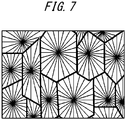
- the membrane produced by the method disclosed in PTL1 has also a problem of having a spherocrystal structure. It is therefore an object of the present disclosure to provide a porous hollow fiber membrane that has a three-dimensional network structure and is excellent in chemical resistance and mechanical strength, a method for producing the porous hollow fiber membrane and a filtration method using the porous hollow fiber membrane.
- a porous hollow fiber membrane that forms a three-dimensional network structure and has an excellent pore forming properties, high chemical resistance and mechanical strength is provided.
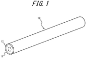
- FIG. 1 is an external view of the porous hollow fiber membrane according to this embodiment.
- a porous hollow fiber membrane 10 includes at least a separation layer 11.
- the porous hollow fiber membrane 10 may be formed only of the separation layer 11, and may further include a support layer 12.
- the porous hollow fiber membrane 10 has the separation layer 11 and the support layer 12.
- the support layer 12 is formed on the inner surface side of the porous hollow fiber membrane 10.
- the separation layer 11 is formed radially outward of the support layer 12.
- the separation layer 11 includes a thermoplastic resin.
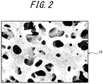
- the inner structure including an outer surface of the porous hollow fiber membrane 10 where the separation layer 11 is formed has a three-dimensional network structure as illustrated in FIG. 2 , rather than a spherocrystal structure.
- the three-dimensional network structure provides higher tensile elongation at break in the porous hollow fiber membrane 10 and higher resistance to acids, alkalis (such as an aqueous sodium hydroxide solution), oxidant and the like, that are often used as a cleaning agent of membranes.
- thermoplastic resin of the separation layer 11 may include polyolefins, copolymers of olefin and olefin halide, polyolefin halides, or mixtures thereof.
- specific examples of such thermoplastic resins may include polyethylene, polypropylene, polyvinyl alcohol, ethylene-vinyl alcohol copolymer, ethylene-tetrafluoroethylene (ETFE) copolymer, ethylene-monochlorotrifluoroethylene (ECTFE) copolymer, copolymer of vinylidene fluoride, ethylene, trifluoroethylene (VDF-TriFE), polyvinylidene fluoride (which may include a domain of hexafluoropropylene), or mixtures thereof.
- these materials are thermoplastic and thus have good handleability as well as high strength, they are excellent membrane materials.
- homopolymers and copolymers of vinylidene fluoride, ethylene, tetrafluoroethylene, chlorotrifluoroethylene, hexafluoropropylene and vinyl fluoride, or mixtures of these homopolymers and/or copolymers are preferred for their excellent mechanical strength and chemical strength (chemical resistance), as well as good formability.
- fluorine resins such as polyvinylidene fluoride, vinylidene fluoride-hexafluoropropylene copolymer, ethylene-tetrafluoroethylene copolymer, and ethylene-chlorotrifluoroethylene copolymer.
- the separation layer 11 contains a component other than the thermoplastic resin (impurities and the like).
- the separation layer 11 may contain components other than the thermoplastic resin in an amount up to about 5% by mass.
- the separation layer 11 contains non-solvents used during production as described later. These non-solvents can be detected by pyrolysis GC-MS (gas chromatography mass spectrometry).
- a non-solvent is an organic liquid that does not uniformly dissolve a thermoplastic resin of one-quarter mass at a boiling point. That is, a non-solvent is an organic liquid that does not uniformly dissolve a thermoplastic resin at a boiling point of the organic liquid in a mixture containing the thermoplastic resin and the organic liquid at a mass ratio of 20:80.
- an organic liquid having the above described properties is selected according to the thermoplastic resin applied to the porous hollow fiber membrane 10.
- the refractive index and the like can be used to determine the dissolved state. For example, in the dissolved state, when a thermoplastic resin and an organic liquid are put in a glass test tube, the same refractive index is obtained wherever in the mixture is measured. In a non-dissolved state, the mixture separates into two layers which respectively indicate refractive indexes different from each other.
- the non-solvent may consist of a plurality of solvents.
- the non-solvent may contain a first organic liquid and a second organic liquid.
- the first organic liquid alone is a non-solvent with respect to the thermoplastic resin.
- the second organic liquid alone is a poor solvent or a good solvent with respect to the thermoplastic resin.
- the poor solvent is an organic liquid that does not uniformly dissolve a thermoplastic resin of one-quarter mass at 25 °C and uniformly dissolves the thermoplastic resin at least at a boiling point. That is, the poor solvent is an organic liquid that does not uniformly dissolve the thermoplastic resin at 25 °C, and uniformly dissolves the thermoplastic resin at 100 °C or more and below the boiling point of the organic liquid, in a mixture containing the thermoplastic resin and the organic liquid at a ratio of 20:80.
- an organic liquid having the above described properties is selected according to the thermoplastic resin applied to the porous hollow fiber membrane 10.
- the good solvent is an organic liquid that uniformly dissolves a thermoplastic resin at 25 °C.
- a good solvent an organic liquid having the above described properties is selected according to the thermoplastic resin applied to the porous hollow fiber membrane 10.
- the first organic liquid is at least one selected from sebacic acid esters, citric acid esters, acetyl citric acid esters, adipic acid esters, trimellitic acid esters, oleic acid esters, palmitic acid esters, stearic acid esters, phosphoric acid esters, phosphorous esters, C6-C30 fatty acids, and epoxidized vegetable oils.
- the second organic liquid is different from the first organic liquid, and is at least one selected from sebacic acid esters, citric acid esters, acetyl citric acid esters, adipic acid esters, trimellitic acid esters, oleic acid esters, palmitic acid esters, stearic acid esters, phosphoric acid esters, phosphorous esters, C6-C30 fatty acids, and epoxidized vegetable oils.
- Examples of the C6-C30 fatty acids include capric acid, lauric acid, oleic acid, and the like.
- Examples of the epoxidized vegetable oils may include epoxidized soybean oil, epoxidized linseed oil, and the like. The above described solvents are compatible with additives and have low toxicity.
- a mixed liquid of the first organic liquid and the second organic liquid is a non-solvent in a mixture containing a thermoplastic resin and the mixed liquid at a ratio of 20:80, and thus does not dissolve a thermoplastic resin even at a boiling point of the mixed liquid.
- the non-solvent may also be a single solvent.
- a non-solvent is at least one selected from sebacic acid esters, acetyl citric acid esters, citric acid esters, adipic acid esters, trimellitic acid esters, oleic acid esters, palmitic acid esters, stearic acid esters, phosphoric acid esters, phosphorous esters, C6-C30 fatty acids and epoxidized vegetable oils, or mixtures thereof.
- the non-solvent is preferably an organic liquid selected from stearic acid esters, phosphoric acid esters and C6-C30 fatty acids.
- Examples of the C6-C30 fatty acids include capric acid, lauric acid, oleic acid, and the like.
- Examples of the epoxidized vegetable oils may include epoxidized soybean oil, epoxidized linseed oil, and the like. The above described solvents are compatible with additives and have low toxicity.
- the separation layer 11 may further contain a poor solvent.
- a poor solvent may include, for example, triphenyl phosphate, oleic acid, and the like.
- the separation layer 11 may further contain an additive as a component other than the thermoplastic resin.
- the additive may preferably be hydrophobic for excellent compatibility with thermoplastic resin and the above described non-solvents.
- Inorganic material may be used as the additive.
- the inorganic material may be an inorganic compound.
- the inorganic compound may preferably be inorganic fine powders. Examples of inorganic fine powders may include silica (including fine powder silica), titanium oxide, lithium chloride, calcium chloride, and the like. Among them, fine powder silica is preferable in view of cost.
- the support layer 12 is a porous body consisting of fluorine resin.
- the fluorine resin is vinylidene fluoride-hexafluoropropylene homopolymer or copolymer or mixtures thereof, ethylene-tetrafluoroethylene copolymer, ethylene-chlorotrifluoroethylene copolymer, or mixtures of the above described fluorine resins.
- the porous hollow fiber membrane 10 has an initial value of tensile elongation at break of preferably 60% or more, more preferably 80% or more, still more preferably 100% or more, and particularly preferably 120% or more.
- the tensile elongation at break can be measured using the measurement method in the Examples described later.
- Alkali resistance can be measured using ratios of elongation at break before and after alkali immersion.
- the porous hollow fiber membrane 10 preferably retains, after immersion in a 4% aqueous NaOH solution for ten days, a tensile elongation at break of 60% or more of the initial value of the tensile elongation at break, more preferably 65% or more, and still more preferably 70% or more.
- the porous hollow fiber membrane 10 has a compression strength of 0.2 MPa or more, preferably 0.3 to 1.0 MPa, and more preferably 0.4 to 1.0 MPa.
- the compression strength measurement pure water permeation amount by the external pressure is measured, the pressure is raised at intervals of 0.05 MPa, and the pressure at which the pressure and the pure water permeation amount are not proportional any more is determined as crush of membrane, then the pressure immediately before that is regarded as the compression strength.
- the surface of the porous hollow fiber membrane 10 has an open fraction (surface open fraction) of 20 to 60%, preferably 25 to 50%, and more preferably 25 to 45%.
- an open fraction surface open fraction
- Use of a membrane having a surface open fraction of 20% or more on the side to be in contact with a liquid to be treated allows for reduction in both degradation of water permeability due to clogging, degradation of water permeability due to chafing of the membrane surface, and increase in filtration stability.
- the open fraction can be measured by the measurement method used in the Examples described below.
- the pore diameter on the outer surface is 1,000 nm or less, preferably 10 to 800 nm, and more preferably 100 to 700 nm.
- the pore diameter is 1,000 nm or less, the components desired to be blocked contained in the liquid to be treated can be blocked, and when the pore diameter is 10 nm or more, sufficiently high water permeability can be ensured.
- the pore diameter can be measured by the measurement method in the Examples described later.
- the porous hollow fiber membrane 10 When the porous hollow fiber membrane 10 is in the form of a single layer membrane of the separation layer 11, the porous hollow fiber membrane 10 has a thickness of preferably 80 to 1,000 ⁇ m, and more preferably 100 to 300 ⁇ m. When the thickness is 80 ⁇ m or more, strength can be increased, and when the thickness is 1,000 ⁇ m or less, pressure loss due to membrane resistance can be reduced.
- the porous hollow fiber membrane 10 When the porous hollow fiber membrane 10 is in the form of a multilayer porous hollow fiber membrane including the support layer 12, the separation layer 11 has a thickness of preferably 1 to 100 ⁇ m, and the support layer 12 has a thickness of preferably 80 to 1,000 ⁇ m.
- the thickness of the separation layer 11 is 1 ⁇ m or more, separation properties can be exhibited easily, and when the thickness is 100 ⁇ m or less, the water permeability is not easily reduced.
- the support layer 12 has a thickness of 80 ⁇ m or more, strength can be increased, and when the thickness thereof is 1,000 ⁇ m or less, pressure loss due to membrane resistance can be reduced.
- the porous hollow fiber membrane 10 has a porosity of preferably 50 to 80%, and more preferably 55 to 65%.
- the porosity being 50% or more allows providing high water permeability, and the porosity being 80% or less allows providing high mechanical strength.
- the wet membrane means a membrane in such a state that the pores are filled with water, but the hollow portions do not contain water.
- the wet membrane can be obtained by immersing a sample membrane of 10 to 20 cm in length in ethanol to fill the pores with ethanol, then immersing the membrane in water repeatedly 4 to 5 times to sufficiently replace the content in the pores with water, then holding one end of the hollow fiber membrane after replacement and shaking the membrane well about 5 times, and furthermore holding another end of the hollow fiber membrane and again shaking it well about 5 times to remove water in the hollow portions.
- the dry membrane can be obtained by drying the wet membrane after being subjected to a measurement of weight in an oven at 80 °C until the membrane reaches constant weight.
- the membrane volume is obtained by the following equation.
- Membrane volume cm 3 ⁇ ⁇ outer diameter cm / 2 2 ⁇ inner diameter cm / 2 2 ⁇ membrane length cm .
- the porous hollow fiber membrane 10 may be in the form of an annular single-layer membrane. However, the porous hollow fiber membrane 10 may be in the form of a multilayer membrane including a separation layer 11 and a support layer 12 supporting the separation layer 11, the pore diameters of these layers being different from each other.
- the outer surface and the inner surface of the porous hollow fiber membrane 10 may have a modified cross-section structure, such as a cross-section structure including protrusions.
- Liquids to be treated with the porous hollow fiber membrane 10 include turbid water and process liquids.
- the porous hollow fiber membrane 10 is suitably used in water purification methods that include filtering turbid water.
- the turbid water refers to natural water, domestic drainage, and treated water of them.
- Examples of the natural water include river water, lake water, groundwater, and sea water.
- the turbid water to be treated also includes treated water of natural water subjected to a treatment, such as sedimentation, sand filtration, coagulating-sedimentation sand filtration, ozone treatment, and activated carbon treatment.
- An example of the domestic drainage is sewage water.
- Examples of the turbid water to be treated also include primary treated water of sewage water subjected to screen filtration or sedimentation, secondary treated water of sewage water subjected to biotreatment, and even tertiary treated (highly treated) water of sewage water subjected to a treatment, such as coagulating-sedimentation sand filtration, activated carbon treatment, and ozone treatment.
- a treatment such as coagulating-sedimentation sand filtration, activated carbon treatment, and ozone treatment.
- Such turbid water contains minute suspensoids on the order of ⁇ m or less including organic substances, inorganic substances, and organic-inorganic mixtures (such as humic colloid, organic colloid, clay, and bacteria).
- Water quality of the turbid water such as the above-described natural water, domestic drainage, and treated water of them can generally be expressed using one of or combination of turbidity and concentration of organic substances, which are representative water quality indexes.
- the turbidity average turbidity rather than instant turbidity
- the water quality can be roughly classified, for example, into low-turbidity water with a turbidity of less than 1, medium-turbidity water with a turbidity of 1 or more and less than 10, high-turbidity water with a turbidity of 10 or more and less than 50, and ultrahigh-turbidity water with a turbidity of 50 or more.
- the water quality can be roughly classified, for example, into low-TOC water with a TOC of less than 1, medium-TOC water with a TOC of 1 or more and less than 4, high-TOC water with a TOC of 4 or more and less than 8, and ultrahigh-TOC water with a TOC of 8 or more.
- water with higher turbidity or TOC is more likely to cause clogging of the filtration membrane, and therefore the effect of using the porous hollow fiber membrane 10 is higher for water with a higher turbidity or a TOC.
- the process liquid refers to a liquid to be separated in a process separating a valuable material and invaluable materials during production of food, drug, semiconductor, etc.
- the porous hollow fiber membrane 10 is used to separate liquor such as, sake or wine from yeast
- the porous hollow fiber membrane 10 is used, for example, for sterile filtration during purification of protein.
- the porous hollow fiber membrane 10 is used, for example, to separate an abrasive from water in polishing wastewater.
- the porous hollow fiber membrane 10 may preferably be any one of the following: a sum of areas of resin portions each having an area of 1 ⁇ m 2 or less is 70% or more to a total area of the resin portions; a sum of areas of resin portions each having an area of 10 ⁇ m 2 or more is 15% or less to a total area of the resin portions; and a sum of areas of resin portions each having an area of 1 ⁇ m 2 or less is 70% or more to a total area of the resin portions and a sum of areas of resin portions each having 10 ⁇ m 2 or more is 15% or less to a total area of the resin portions.
- a sum of areas of resin portions each having an area of 1 ⁇ m 2 or less is 70% or more to a total area of the resin portions, a sum of areas of resin portions each having an area over 1 ⁇ m 2 and less than 10 ⁇ m 2 is 15% or less to a total area of the resin portions, and a sum of areas of resin portions each having an area of 10 ⁇ m 2 or more is 15% or less to a total area of the resin portions.
- FIG. 3 is an example of an SEM image illustrating a cross-section of the porous hollow fiber membrane 10 according to this embodiment.
- This SEM image is obtained through binarization of an SEM image picture obtained by taking an image of a specific field of view in a region closest to an inner side of a total of four fields of view including, in an SEM image of a membrane cross-section in a membrane thickness direction orthogonal to an inner surface of the porous hollow fiber membrane 10, a field of view including the inner surface, a field of view including an outer surface of the porous hollow fiber membrane 10 and two fields of view taken at equal intervals between these fields of view.
- resin portion is a dendritic skeleton portion of a three-dimensional network structure formed of resin, and forms a number of pores in the porous hollow fiber membrane 10.
- the resin portions are indicated in black and the pores are indicated in white.
- flux (amount of permeated water, water permeability) of the liquid to be treated is high, retention of permeated water after cleaning is high, and damage to the membrane after chemical cleaning represented by tensile elongation at break can be reduced.
- a ratio of the sum of areas of resin portions each having an area of 1 ⁇ m 2 or less to a total area of the resin portions is too high, a dendritic skeleton portion of a three-dimensional network structure formed of resin, which forms a number of pores in the porous hollow fiber membrane 10 becomes too thin.
- a sum of areas of resin portions each having an area of 1 ⁇ m 2 or less is maintained to be 70% or more to a total area of the resin portions, it is preferable that a sum of areas of resin portions each having an area over 1 ⁇ m 2 be 2% or more and 30% or less to a total area of the resin portions, it is more preferable that a sum of areas of resin portions each having an area of 10 ⁇ m 2 or more be 15% or less to a total area of the resin portions, and it is still preferable that a sum of areas of resin portions each having an area of over 1 ⁇ m 2 and less than 10 ⁇ m 2 be 15% or less to a total area of the resin portions and a sum of areas of resin portions each having an area of 10 ⁇ m 2 or more be 2% or more and 15% or less to a total area of the resin portions.
- a sum of areas of resin portions each having an area over 1 ⁇ m 2 is 2% or more and 30% or less to a total area of the resin portions, since the dendritic skeleton portion of a three-dimensional network structure formed of resin is not too thin, the strength and the tensile elongation at break of the porous hollow fiber membrane 10 can be suitably maintained.
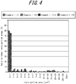
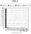
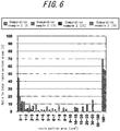
- FIGS. 4 to 6 are histograms each illustrating a ratio (%) of a sum of areas of resin portions each having a predetermined area to a total area of the resin portions in each region ((I) to (IV)) of a total of four fields of view including, in an SEM image of a membrane cross-section in a membrane thickness direction orthogonal to an inner surface of the porous hollow fiber membrane 10 used by Example 1, Example 4 and Comparative example 2, a field of view including the inner surface, a field of view including an outer surface of the porous hollow fiber membrane 10 and two fields of view taken at equal intervals between these fields of view.
- the resin portions appear in a granular form.
- Areas of resin portions in a granular form are each measured, and with respect to each area of resin portion in a granular form, a ratio of each area to a total area of the resin portions in a field of view of a predetermined size in each region is indicated as histograms illustrated in FIGS. 4 to 6 .
- FIGS. 4 to 6 illustrate histograms illustrated in FIGS. 4 to 6 .
- I is a symbol indicating a region closest to the inner side of a total of four fields of view
- IV is a symbol indicating a region closest to the inner side thereof
- the four fields of view including, in an SEM image of a membrane cross-section in a membrane thickness direction orthogonal to an inner surface of the porous hollow fiber membrane 10, a field of view including the inner surface, a field of view including an outer surface of the porous hollow fiber membrane and two fields of view taken at equal intervals between these fields of view.
- I of Example 1 is a histogram of an image of a field of view having a predetermined size in an innermost region of the porous hollow fiber membrane of Example 1. A measurement method of area distribution of resin portions in each region of the porous hollow fiber membrane will be described later.
- the method for producing the porous hollow fiber membrane 10 includes the steps of: (a) preparing a melt-kneaded product; (b) feeding the melt-kneaded product to a multiple-structure spinning nozzle and extruding the melt-kneaded product through the spinning nozzle to obtain a hollow fiber membrane; (c) extracting a non-solvent from the hollow fiber membrane; and (d) extracting inorganic fine powder from the hollow fiber membrane.
- the separation layer 11 and the support layer 12 each includes steps (a) and (b), in which a triple tubular spinning nozzle is used and a melt-kneaded product, which will be the separation layer 11 and the support layer 12, is extruded into an outermost tube and a middle tube of the triple tube, and a hollow forming agent is poured into an inner tube to form a hollow portion.
- phase separation may preferably be liquid-liquid phase separation, that is similar to the thermally induced phase separation.
- a non-solvent and inorganic fine powder are extracted from the hollow fiber membrane, and the hollow fiber membrane after extraction includes a non-solvent and inorganic fine powder as residues.
- a liquid such as methylene chloride or various alcohols, that does not dissolve a thermoplastic resin and has high affinity with plasticizer is preferably used.
- a liquid such as hot water, or an acid or alkali that can dissolve the additive used but does not dissolve a thermoplastic resin is preferably used.
- the above described step (a) includes causing an inorganic compound to absorb the non-solvent for powderization and melt-kneading the powder and a thermoplastic resin. Therefore, the melt-kneaded product contains three components such as a thermoplastic resin, a non-solvent and inorganic fine powder.
- thermoplastic resin used in the step (a) for example, polyolefins, copolymers of an olefin and a olefin halide, polyolefin halides, or mixtures thereof are used as described above.
- specific examples of the above described thermoplastic resins include, for example, polyethylene, polypropylene, polyvinyl alcohol, ethylene-vinyl alcohol copolymer, ethylene-tetrafluoroethylene copolymer, polyvinylidene fluoride (which may include a domain of hexafluoropropylene), or mixtures thereof. Since these materials are thermoplastic and thus have excellent handleability as well as high strength, they are excellent membrane materials.
- homopolymers and copolymers of vinylidene fluoride, ethylene, tetrafluoroethylene, and chlorotrifluoroethylene, or mixtures of these homopolymers and/or copolymers are preferred for their excellent mechanical strength and chemical strength (chemical resistance), as well as good formability.
- fluorine resins such as polyvinylidene fluoride, vinylidene fluoride-hexafluoropropylene copolymer, ethylene-tetrafluoroethylene copolymer, and ethylene-chlorotrifluoroethylene copolymer may preferably be used.
- the thermoplastic resin in the melt-kneaded product has a concentration of preferably 20 to 60 % by mass, more preferably 25 to 45 % by mass, and still more preferably 30 to 45 % by mass.
- concentration being 20 % by mass or more allows providing higher mechanical strength, and the concentration being 60 % by mass or less allows providing higher water permeability.
- a mixed liquid which is a non-solvent as a whole, contains a first organic liquid and a second organic liquid
- a non-solvent to the thermoplastic resin be used as a first organic liquid used for the step (a). It is also preferable that, as a second organic liquid used for the step (a), a good solvent or a poor solvent to the thermoplastic resin be used.
- a non-solvent to the thermoplastic resin is mixed into a good solvent or a poor solvent.
- the concentration of the first organic liquid in the melt-kneaded product is preferably 10 to 60 % by mass.
- concentration of the second organic liquid in the melt-kneaded product is preferably 20 to 50 % by mass.
- a non-solvent and a poor solvent or a good solvent are selected, for example, from sebacic acid esters, citric acid esters, acetyl citric acid esters, adipic acid esters, trimellitic acid esters, oleic acid esters, palmitic acid esters, stearic acid esters, phosphoric acid esters, phosphorous esters, C6-C30 fatty acids, and epoxidized vegetable oils.
- An organic liquid that can dissolve a thermoplastic resin in a temperature range from 25 °C to 100 °C is referred to as a good solvent
- an organic liquid that can dissolve a thermoplastic resin in a temperature range from 100 °C to the boiling point is referred to as a poor solvent
- an organic liquid that cannot dissolve a thermoplastic resin at the boiling point or higher is referred to as a non-solvent.
- a good solvent, a poor solvent and a non-solvent can be determined as follows.
- a good solvent applicable as the second organic liquid is at least one selected from various esters such as sebacic acid esters, citric acid esters, acetyl citric acid esters, adipic acid esters, trimellitic acid esters, oleic acid esters, palmitic acid esters, stearic acid esters, phosphoric acid esters, phosphorous esters, C6-C30 fatty acids and epoxidized vegetable oils, and is an organic liquid that uniformly dissolves the thermoplastic resin in a mixed liquid obtained by mixing the solvent four times the mass of the thermoplastic resin at any temperature in a range from higher than 25 °C to the boiling point or lower.
- esters such as sebacic acid esters, citric acid esters, acetyl citric acid esters, adipic acid esters, trimellitic acid esters, oleic acid esters, palmitic acid esters, stearic acid esters, phosphoric acid esters, phosphorous esters, C6-C30 fatty
- a poor solvent applicable as the second organic liquid is at least one selected from various esters such as sebacic acid esters, citric acid esters, acetyl citric acid esters, adipic acid esters, trimellitic acid esters, oleic acid esters, palmitic acid esters, stearic acid esters, phosphoric acid esters, phosphorous esters, C6-C30 fatty acids, and epoxidized vegetable oils, and is an organic liquid that does not uniformly dissolve the thermoplastic resin in a mixed liquid obtained by mixing the solvent four times the mass of the thermoplastic resin at 25 °C and uniformly dissolves the thermoplastic resin in the mixed liquid at any temperature in a range from higher than 100 °C to the boiling point or lower.
- esters such as sebacic acid esters, citric acid esters, acetyl citric acid esters, adipic acid esters, trimellitic acid esters, oleic acid esters, palmitic acid esters, stearic acid esters,
- a non-solvent applicable as the first organic liquid is at least one selected from various esters such as sebacic acid esters, citric acid esters, acetyl citric acid esters, adipic acid esters, trimellitic acid esters, oleic acid esters, palmitic acid esters, stearic acid esters, phosphoric acid esters, phosphorous esters, C6-C30 fatty acids, and epoxidized vegetable oils, and is an organic liquid that does not uniformly dissolve the thermoplastic resin in a mixed liquid obtained by mixing the solvent four times the mass of the thermoplastic resin at the boiling point.
- esters such as sebacic acid esters, citric acid esters, acetyl citric acid esters, adipic acid esters, trimellitic acid esters, oleic acid esters, palmitic acid esters, stearic acid esters, phosphoric acid esters, phosphorous esters, C6-C30 fatty acids, and epoxidized vegetable oils
- whether the solvent is a good solvent, a poor solvent, or a non-solvent is determined as follows.
- a thermoplastic resin in an amount of about 2 g and an organic liquid in an amount of about 8 g are put in a test tube, which is heated using a test tube block heater to the boiling point of the organic liquid with intervals of about 10 °C, and a mixture in the test tube is mixed using a spatula or the like.
- the solvent is a good solvent, a poor solvent, or a non-solvent is determined based on solubility at temperatures in the above-described ranges. That is, a solvent that dissolves the thermoplastic resin is a good solvent or a poor solvent, and a solvent that does not dissolve the thermoplastic resin is a non-solvent.
- Boiling points of some of the esters described above as examples of the first organic liquid and the second organic liquid are as follows. Acetyl tributyl citrate has a boiling point of 343 °C, dibutyl sebacate has a boiling point of 345 °C, dibutyl adipate has a boiling point of 305 °C, di-isobutyl adipate has a boiling point of 293 °C, bis (2-ethylhexyl) adipate has a boiling point of 335 °C, diisononyl adipate has a boiling point of 250 °C or more, diethyl adipate has a boiling point of 251 °C, triethyl citrate has a boiling point of 294 °C, and triphenyl phosphite has a boiling point of 360 °C.
- PVDF polyvinylidene fluoride
- acetyl tributyl citrate, dibutyl sebacate or dibutyl adipate is used as the organic liquid
- PVDF is not uniformly dissolved in these solvents at 25 °C, and when the temperature of mixed liquid is raised, PVDF is uniformly mixed and dissolved in the solvent at any temperature in a range from higher than 100 °C to the boiling point or lower. Therefore, acetyl tributyl citrate, dibutyl sebacate and dibutyl adipate are poor solvents to PVDF.
- ETFE ethylene-tetrafluoroethylene copolymer
- diethyl adipate is used as the organic liquid to be mixed
- ETFE is not uniformly dissolved at 25 °C, and is uniformly mixed and dissolved at any temperature in a range from 100 °C or higher and the boiling point or lower. Therefore diethyl adipate is a poor solvent to ETFE.
- bis (2-ethylhexyl) adipate, diisononyl adipate, or a capric acid is used as the organic liquid, ETFE is not dissolved. Therefore, bis (2-ethylhexyl) adipate, diisononyl adipate and capric acid are non-solvents to ETFE.
- ECTFE ethylene-monochlorotrifluoroethylene copolymer
- triethyl citrate or bis (2-ethylhexyl) adipate is used as the organic liquid to be mixed
- ECTFE is not uniformly dissolved at 25 °C and ECTFE is uniformly dissolved at any temperature in a range from 100 °C or higher and the boiling point or lower. Therefore, triethyl citrate and bis (2-ethylhexyl) adipate are poor solvents to ECTFE.
- triphenyl phosphite or an oleic acid is used as the organic liquid, ECTFE is not dissolved. Therefore triphenyl phosphite and an oleic acid are non-solvents to ECTFE.
- PE polyethylene
- dibutyl sebacate is used as the organic liquid to be mixed
- PE is not uniformly dissolved at 25 °C
- PE is uniformly mixed and dissolved at any temperature in a range from 100 °C or higher to the boiling point or lower. Therefore dibutyl sebacate is a poor solvent to PE.
- bis (2-ethylhexyl) adipate or acetyl tributyl citrate is used as the organic liquid, PE is not dissolved. Therefore bis (2-ethylhexyl) adipate and acetyl tributyl citrate are non-solvents to PE.
- a non-solvent contains a single solvent
- a non-solvent used for the step (a) among at least one selected from sebacic acid esters, citric acid esters, acetyl citric acid esters, adipic acid esters, trimellitic acid esters, oleic acid esters, palmitic acid esters, stearic acid esters, phosphoric acid esters, phosphorous esters, C6-C30 fatty acids and epoxidized vegetable oils or a mixture of some of them, an organic liquid that does not uniformly dissolve the thermoplastic resin of one-quarter mass at a boiling point is applied.
- a non-solvent is preferably at least one selected from stearic acid esters, phosphorous esters and fatty acids. Concentration of the non-solvent in the melt-kneaded product is preferably 10 to 60% by mass.
- a non-solvent of ethylene-chlorotrifluoroethylene copolymer is used as a raw material.
- a non-solvent is used as a raw material of the membrane, a porous hollow fiber membrane having a three-dimensional network structure is obtained.
- the non-solvent alone does not mix with the ethylene-chlorotrifluoroethylene copolymer.
- the organic liquid that is capable of dissolving the thermoplastic resin at ordinary temperatures is referred to as a solvent
- the organic liquid that is not capable of dissolving the thermoplastic resin at ordinary temperatures but is capable of dissolving the thermoplastic resin at high temperatures is referred to as a poor solvent to the thermoplastic resin
- the organic liquid that is not capable of dissolving the thermoplastic resin even at high temperatures is referred to as a non-solvent.
- the poor solvent and the non-solvent can be determined by the method described below.
- the non-solvent contains a single solvent
- the non-solvent is an organic liquid that does not uniformly dissolve the thermoplastic resin in a first mixed liquid even if the temperature of the first mixed liquid is raised to the boiling point, the first mixed liquid being obtained by mixing the solvent four times the mass of the thermoplastic resin, which is ethylene-chlorotrifluoroethylene copolymer.
- the poor solvent is an organic liquid that does not uniformly dissolve the thermoplastic resin in a second mixed liquid at 25 °C but uniformly dissolves the thermoplastic resin therein at any temperature in a range from higher than 100 °C to the boiling point or lower, the second mixed liquid being obtained by mixing the solvent four times the mass of the thermoplastic resin, which is ethylene-chlorotrifluoroethylene copolymer.
- whether the solvent is a poor solvent or a non-solvent is determined as follows. Ethylene-chlorotrifluoroethylene copolymer in an amount of about 2 g and an organic liquid in an amount of about 8 g are put in a test tube, which is heated using a test tube block heater to the boiling point of the organic liquid with intervals of about 10 °C, and a mixture in the test tube is mixed using a spatula or the like. Then whether the solvent is a poor solvent or a non-solvent is determined based on solubility at temperatures in the above-described ranges.
- Boiling points of some of the esters described above as examples of non-solvents are as follows. Acetyl tributyl citrate has a boiling point of 343 °C, dibutyl sebacate has a boiling point of 345 °C, dibutyl adipate has a boiling point of 305 °C, di-isobutyl adipate has a boiling point of 293 °C, bis (2-ethylhexyl) adipate has a boiling point of 335 °C, diisononyl adipate has a boiling point of 250 °C or more, diethyl adipate has a boiling point of 251 °C, triethyl citrate has a boiling point of 294 °C, and triphenyl phosphite has a boiling point of 360 °C.
- ethylene-chlorotrifluoroethylene copolymer is used as the thermoplastic resin and triethyl citrate is used as the organic liquid to be mixed, they are uniformly mixed at about 200 °C. Thus triethyl citrate is applicable as a poor solvent.
- triphenyl phosphate or oleic acid is used as the organic liquid, ethylene-chlorotrifluoroethylene copolymer is not dissolved at the boiling points thereof, thus is applicable as a non-solvent.
- an additive used in the step (a) may be an inorganic material such as an inorganic compound or an organic material.
- the inorganic material is preferably inorganic fine powder.
- the inorganic fine powder contained in the melt-kneaded product has a primary particle size of preferably 50 nm or less, and more preferably 5 nm or more and less than 30 nm.
- Specific examples of the inorganic fine powder include silica (including fine powder silica), titanium oxide, lithium chloride, calcium chloride, organic clay, and the like. Among them, fine powder silica is preferred in view of cost.
- the "primary particle size of the inorganic fine powder” refers to a value that is found through analysis of an electron micrograph. That is, first, a batch of inorganic fine powder is pre-treated according to the method prescribed in ASTM D3849. Thereafter, diameters of 3000 to 5000 particles on a transmission electron micrograph are measured, and an arithmetic average of these values is calculated as the primary particle size of the inorganic fine powder.
- the material of the inorganic fine powder present in the porous hollow fiber membrane 10 can be determined by identifying elements present therein by fluorescent X-ray analysis and the like. Organic clay and the like may preferably be used when an organic material is used as additive.
- the above described non-solvent is not mixed with the thermoplastic resin.
- the inorganic fine powder is used to absorb the oil of the non-solvent to powderize the non-solvent, and the thermoplastic resin powder is mixed therewith. Further, a mixture of these non-solvent, inorganic fine powder and thermoplastic resin is melt-kneaded at about 240 °C to obtain uniform mixture thereof, which allows the thermoplastic resin to be in a melting state.
- the material of the inorganic fine powder in the porous hollow fiber membrane can be determined by identifying the elements present in the inorganic fine powder by fluorescent X-ray and the like.
- the filtration method according to this disclosure includes performing filtration of the liquid to be treated using the porous hollow fiber membrane 10 of this disclosure.
- Using the porous hollow fiber membrane 10 of this disclosure enables highly efficient filtration.
- the hollow fiber membrane was cut into thin slices with a razor, and the outer diameter and the inner diameter thereof were measured using a 100x magnifying glass. For each sample, measurement was performed at 60 points at 30-mm intervals.
- An electron microscope, SU8000 series, available from HITACHI was used to obtain 5000x electron microscope (SEM) images of the surface and the cross-section of each membrane with an accelerating voltage of 3 kV.
- the electron microscope sample of the cross-section was obtained by slicing a membrane sample that was frozen in ethanol.
- an image analysis software, Winroof6.1.3 was used to perform "noise removal" of the SEM images with a value "6”, and further binarizaion was performed with a single threshold value, which is "threshold value:105.”
- the open fraction on the membrane surface was calculated by calculating the areas occupied by pores on thus obtained binarized images.
- pore size an areas of each pore was added in the ascending order of a pore size, and the pore size at which the sum thereof reached 50% of the total areas of all pores was determined as the pore size.
- membrane structure As for membrane structure, the images of the membrane surface and the cross-section taken at 5000 ⁇ were observed, and a membrane that had no spherocrystals and had polymer trunks exhibiting a three-dimensional network structure was determined as having a three-dimensional network structure.
- the effective membrane length refers to a net length of the membrane excluding the length of the portion in which the syringe needle is inserted.
- the water permeability retention during filtration of turbid water is an index used to determine the degree of degradation of water permeability due to clogging (fouling).
- Each wet hollow fiber membrane was immersed in ethanol and then immersed in pure water several times, and was filtrated according to the external pressure method with an effective membrane length of 11 cm.
- pure water was filtered under such a filtration pressure that the pure water permeated at a rate of 10 m 3 per day per outer surface area of the membrane of 1 m 2 , and the permeated water was collected for 2 minutes. The resulting value was determined as an initial pure water permeability.
- the filtration pressure for the turbid water was set such that the filtration pressure was not uniform across the membranes, and that the initial pure water permeability (which is the same as the water permeability at the start of filtration of turbid water) was at a rate of 10 m 3 per day per 1 m 2 of the outer surface area of the membrane.
- membranes are usually used in a constant rate filtration operation (where the filtration pressure is adjusted such that a fixed amount of filtered water is obtained within a fixed amount of time), and it was contemplated to allow, in this measurement using a single hollow fiber membrane, comparison of the water permeability degradation under conditions as close as possible to the conditions of the constant rate filtration operation.
- Each porous hollow fiber membrane was wet by 100% ethanol and then replaced with pure water. Each wetted porous hollow fiber membrane was cut into a length of 10 cm, and 20 pieces of them were immersed in 500 ml of a 4% aqueous sodium hydroxide solution for ten days and kept at 40° C. Tensile elongation at break of the membrane before and after the immersion in sodium hydroxide was measured for 20 samples, and the average value thereof was calculated. An elongation retention, which is defined as 100 ⁇ (Elongation after immersion)/(Elongation before immersion), was used to evaluate chemical resistance.
- the porous hollow fiber membrane was cut into an annular shape through a cross-section orthogonal to a length direction, stained with 10% phosphotungstic acid + osmium tetroxide, and embedded in epoxy resin, which was trimmed. Further, a sample cross-section thereof was subjected to BIB processing to obtain a flat and smooth cross-section, which was subjected to conductive treatment to produce a microscopic observation sample.
- SU8000 series available from HITACHI, 5000 to 30,000 ⁇ electron microscope (SEM) images of the membrane cross-section of each of thus obtained microscopic observation samples were taken with an accelerating voltage of 1 kV in each region ((I) to (IV) in FIGS.
- the four fields of view include a field of view including an inner surface of a membrane thickness (wall-thickness portion) cross-section, a field of view including an outer surface of the membrane and two fields of view taken at equal intervals between these fields of view.
- Magnification can be changed according to the average power size, and more specifically, 5,000 ⁇ for the average pore diameter of 0.1 ⁇ m or more, 10,000 ⁇ for the average diameter of 0.05 ⁇ m or more and less than 0.1 ⁇ m and 30,000 ⁇ for the average diameter of less than 0.05 ⁇ m.
- the size of each field of view was 2560 ⁇ 1920 pixels.
- ImageJ was used for image processing, and threshold processing was performed on an SEM image (Image-Adjust-Treshold: Otsu's method (Otsu was selected)) to binarize on pore portions and resin portions.
- ImageJ's "Analyze Particle" command (Analyz Particle: Size 0.10-Infinity) was used to measure each size of binarized granular resin portions contained in the SEM image.
- the total area of all resin portions contained in the SEM image was defined as ⁇ S and the area of the resin portions having 1 ⁇ m 2 or less was defined as ⁇ S ( ⁇ 1 ⁇ m 2 ), and ⁇ S ( ⁇ 1 ⁇ m 2 )/ ⁇ S was calculated to determine a ratio of the area of the resin portions having an area of 1 ⁇ m 2 or less. In the same manner, a ratio of the area of the resin portions having an area of a predetermined range was calculated.
- the resin portions having an area of less than 0.1 ⁇ m 2 were removed as noise, and the resin portions having an area of 0.1 ⁇ m 2 or more were defined as targets for analyze.
- Noise removal was performed through median filter processing (Process-Filters-Median:Radius: 3.0 pixels).
- Each granular resin portion whose part is missing at the edge of the SEM image was also defined as a target for measurement. "Incude Holes” processing was not performed. Further, shape correction such as correcting from “snowman” shape into “flat” shape was not performed.
- a melt-kneaded product was extruded by using a double-tube spinning nozzle to obtain a porous hollow fiber membrane of Example 1.
- a thermoplastic resin 40% by mass of PVDF resin (Solef 6010 available from Solvay Specialty Polymers) was used, as an additive, 23% by mass of fine powder silica (R972 available from Japan Aerosil Co., Ltd.) was used, as a first organic liquid, 32% by mass of bis (2-ethylhexyl) adipate (DOA having a boiling point of 335 °C available from Tokyo Chemical Industry Co., Ltd.) was used, and as a second organic liquid, 5% by mass of acetyl tributyl citrate (ATBC having a boiling point of 343 °C available from Tokyo Chemical Industry Co., Ltd.) was used to prepare the melt-kneaded product.
- the temperature of the melt-kneaded product was about 200 °C to 250 °C.
- An extruded hollow fiber molded product was allowed to pass through a free traveling distance of 120 mm, and then to solidify in water at 30° C to produce a porous hollow fiber membrane by the melt-forming method, the membrane was taken up on a reel at a speed of 5 m/minute.
- hollow fiber extrudate was immersed in isopropyl alcohol to extract and remove the bis (2-ethylhexyl) adipate and the acetyl tributyl citrate, and then was immersed in water for 30 minutes for water replacement of hollow fiber membrane. Subsequently the hollow fiber extrudate was immersed in a 20 % by mass of aqueous NaOH solution at 70° C for one hour, and repeatedly washed with water to extract and remove the fine powder silica.
- Table 1 indicates the formulation, production conditions, and various performances of the obtained porous hollow fiber membrane of Example 1.
- the membrane structure of the porous hollow fiber membrane of Example 1 exhibited a three-dimensional network structure as illustrated in FIG. 2 .
- a porous hollow fiber membrane was produced in the same manner as in Example 1, except that a melt-kneaded product was prepared by using 5% by mass of dibutyl sebacate (DBS having a boiling point of 345 °C available from Tokyo Chemical Industry Co., Ltd.) instead of 5% by mass of acetyl tributyl citrate (ATBC having a boiling point of 343 °C available from Tokyo Chemical Industry Co., Ltd.).
- DBS dibutyl sebacate
- ATBC acetyl tributyl citrate
- Table 1 indicates the formulation, production conditions, and various performances of the obtained porous hollow fiber membrane of Example 2.
- the membrane structure of the porous hollow fiber membrane of Example 2 exhibited a three-dimensional network structure as illustrated in FIG. 2 .
- a porous hollow fiber membrane was produced in the same manner as in Example 1, except that the melt-kneaded product was prepared by using 32% by mass of diisononyl adipate (DINA having a boiling point of 250 °C available from Tokyo Chemical Industry Co., Ltd.) instead of 32% by mass of bis (2-ethylhexyl) adipate (DOA having a boiling point of 335 °C) as a first organic liquid.
- DINA diisononyl adipate
- DOA bis (2-ethylhexyl) adipate
- Table 1 indicates the formulation, production conditions, and various performances of the obtained porous hollow fiber membrane of Example 3.
- the membrane structure of the porous hollow fiber membrane of Example 3 exhibited a three-dimensional network structure as illustrated in FIG. 2 .
- a hollow fiber membrane of Comparative Example 1 was obtained in the same manner as Example 1, except that PVDF resin (KF-W#1000, available from Kureha Corporation) was used and a melt-kneaded product was prepared without mixed with the first organic liquid.
- Table 2 indicates the formulation, production conditions, and various performances of the obtained porous hollow fiber membrane of Comparative Example 1.
- the porous hollow fiber membrane structure of Comparative Example 1 exhibited a spherocrystal structure illustrated in FIG. 7 .
- Example 1 Example 2
- Example 3 Thermoplastic resin PVDF Solef 6010 40% by mass PVDF Solef 6010 40% by mass PVDF Solef 6010 40% by mass Additive Fine powder silica 23 % by mass Fine powder silica 23% by mass Fine powder silica 23% by mass First organic liquid (non-solvent) DOA 32% by mass DOA 32% by mass DINA 32% by mass Second organic liquid (poor solvent) ATBC 5% by mass DBS 5% by mass ATBC 5% by mass Discharge temperature of membrane-forming stock solution [°C] 240 240 240 Congealed liquid Water Water Water Congealed liquid temperature [°C] 30 30 30 30
- Free traveling distance [mm] 120 120 120 Pore diameter [nm] 400 350 Pore structure Three-dimensional network structure Three-dimensional network structure Three-dimensional network structure Surface open fraction [%] 30 30
- Examples 1 to 3 demonstrated that, in the membrane formation by using the melt-forming method, a porous hollow fiber membrane having an excellent pore forming properties and high chemical resistance and mechanical strength can be produced by mixing a non-solvent in a membrane-forming stock solution.
- pore has a spherocrystal structure and has less pore forming properties, chemical resistance and mechanical strength.
- a melt-kneaded product was extruded by using a double-tube spinning nozzle to obtain a porous hollow fiber membrane of Example 4.
- a thermoplastic resin 40% by mass of ethylene-chlorotrifluoroethylene copolymer (ECTFE) resin (Halar 901 available from Solvay Specialty Polymers) was used, as inorganic fine powder, 23% by mass of fine powder silica (R972 available from Japan Aerosil Co., Ltd.) was used, and as a non-solvent, 37% by mass of triphenyl phosphate (TPP having a boiling point of 360 °C available from Tokyo Chemical Industry Co., Ltd.) was used to prepare the melt-kneaded product at 240 °C to produce a porous hollow fiber membrane.
- ECTFE ethylene-chlorotrifluoroethylene copolymer
- a porous hollow fiber membrane was produced in the same manner as in Example 4, except that the melt-kneaded product was prepared by using 37% by mass of ethylhexyl stearate (having a boiling point of 340 °C available from Tokyo Chemical Industry Co., Ltd.) instead of 37% by mass of TPP as a non-solvent.
- the porous hollow fiber membrane of Example 5 exhibited a three-dimensional network structure illustrated in FIG. 2 .
- a porous hollow fiber membrane was produced in the same manner as in Example 4, except that the melt-kneaded product was prepared by using 37% by mass of oleic acid (having a boiling point of 285 °C available from Tokyo Chemical Industry Co., Ltd.) instead of 37% by mass of triphenyl phosphite (TPP having a boiling point of 360 °C) as a non-solvent.
- oleic acid having a boiling point of 285 °C available from Tokyo Chemical Industry Co., Ltd.
- TPP triphenyl phosphite
- the porous hollow fiber membrane structure of Example 6 exhibited a three-dimensional network structure illustrated in FIG. 2 .
- a melt-kneaded product was extruded by using a triple-tube spinning nozzle to obtain a multilayer porous hollow fiber membrane of Example 7.
- ECTFE ethylene-chlorotrifluoroethylene copolymer
- thermoplastic resin 25.4% by mass of fine powder silica (R972 available from Japan Aerosil Co., Ltd.), and 40.6% by mass of triphenyl phosphite (TPP having a boiling point of 360°C available from Tokyo Chemical Industry Co., Ltd.) as a non-solvent were used.
- polyvinylidene fluoride resin Solef 6010 available from Solvay Specialty Polymers
- thermoplastic resin 23% by mass of fine powder silica (R972 available from Japan Aerosil Co., Ltd.), 31.3% by mass of bis (2-ethylhexyl) adipate (DOA having a boiling point of 335 °C available from Tokyo Chemical Industry Co., Ltd.) as a non-solvent
- DOA bis (2-ethylhexyl) adipate
- DOA bis (2-ethylhexyl) adipate
- ATBC acetyl tributyl citrate
- a melt-kneaded product was extruded by using a triple-tube spinning nozzle to obtain a multilayer porous hollow fiber membrane of Example 8.
- ECTFE ethylene-chlorotrifluoroethylene copolymer
- thermoplastic resin 25.4% by mass of fine powder silica (R972 available from Japan Aerosil Co., Ltd.), and 40.6% by mass of ethylhexyl stearate (having a boiling point of 340 °C available from Tokyo Chemical Industry Co., Ltd.) as a non-solvent
- ECTFE ethylene-chlorotrifluoroethylene copolymer
- TL-081 available from Asahi Glass Co., Ltd.
- thermoplastic resin 23% by mass of fine powder silica (R972 available from Japan Aerosil Co., Ltd.), 32.9% by mass of bis (2
- a hollow fiber membrane of Comparative Example 2 was obtained in the same manner as Example 4, except that PVDF resin (KF-W#1000, available from Kureha Corporation) was used instead of ECTFE resin as a thermoplastic resin, fine powder silica was not used and only ⁇ -butyrolactone was used as a poor solvent to PVDF resin instead of TPP as a non-solvent.
- the porous hollow fiber membrane structure of Comparative Example 2 exhibited a spherocrystal structure illustrated in FIG. 7 .
- Tables 3 and 4 show the formulation, production conditions, and various performances of the obtained porous hollow fiber membrane of Examples and Comparative Examples.
- Example 4 Example 5
- Example 6 Comparative Example 2
- Resin ECTFE Halar901 ECTFE Halar901 ECTFE Halar902 PVDFKFW#1000 40% by mass 40% by mass 40% by mass 40% by mass 40% by mass Inorganic fine powder Fine powder silica 23% by mass Fine powder silica 23% by mass Fine powder silica 23% by mass none Organic liquid TPP 37% by mass Ethylhexyl stearate 37% by mass Oleic acid 37% by mass ⁇ -butyrolactone Discharge temperature of membrane-forming stock solution [°C] 240 240 240 200 Congealed liquid Water Water Water Water Congealed liquid temperature [°C] 30 30 30 30
- Examples 4 to 8 demonstrated that, in the membrane formation by using the melt-forming method, a porous hollow fiber membrane having an excellent pore forming properties and high chemical resistance and mechanical strength can be produced by using a non-solvent as a membrane-forming stock solution.
- pore has a spherocrystal structure and has less pore forming properties, chemical resistance and mechanical strength.
- a non-solvent is contained to produce a porous hollow fiber membrane.
- a porous hollow fiber membrane having an excellent pore forming properties and high chemical resistance and mechanical strength is provided.
Landscapes
- Chemical & Material Sciences (AREA)
- Chemical Kinetics & Catalysis (AREA)
- Engineering & Computer Science (AREA)
- Manufacturing & Machinery (AREA)
- Health & Medical Sciences (AREA)
- Medicinal Chemistry (AREA)
- Polymers & Plastics (AREA)
- Organic Chemistry (AREA)
- Separation Using Semi-Permeable Membranes (AREA)
- Artificial Filaments (AREA)
Applications Claiming Priority (3)
| Application Number | Priority Date | Filing Date | Title |
|---|---|---|---|
| JP2017168522 | 2017-09-01 | ||
| JP2017168523 | 2017-09-01 | ||
| PCT/JP2018/032464 WO2019045069A1 (ja) | 2017-09-01 | 2018-08-31 | 多孔性中空糸膜、多孔性中空糸膜の製造方法、およびろ過方法 |
Publications (2)
| Publication Number | Publication Date |
|---|---|
| EP3677331A1 true EP3677331A1 (de) | 2020-07-08 |
| EP3677331A4 EP3677331A4 (de) | 2020-11-18 |
Family
ID=65527554
Family Applications (1)
| Application Number | Title | Priority Date | Filing Date |
|---|---|---|---|
| EP18849559.2A Withdrawn EP3677331A4 (de) | 2017-09-01 | 2018-08-31 | Poröse hohlfasermembran, herstellungsverfahren für poröse hohlfasermembran und filtrationsverfahren |
Country Status (5)
| Country | Link |
|---|---|
| US (1) | US11110402B2 (de) |
| EP (1) | EP3677331A4 (de) |
| JP (1) | JP7244426B2 (de) |
| CN (1) | CN111050889B (de) |
| WO (1) | WO2019045069A1 (de) |
Families Citing this family (4)
| Publication number | Priority date | Publication date | Assignee | Title |
|---|---|---|---|---|
| AU2018327797B2 (en) * | 2017-09-07 | 2021-05-20 | Asahi Kasei Kabushiki Kaisha | Method for manufacturing brewed alcoholic beverage using porous membrane |
| CN110964271A (zh) * | 2019-11-27 | 2020-04-07 | 厦门江天智能仿生科技有限公司 | 一种复合膜及其制备方法及其制备设备 |
| WO2022094162A1 (en) * | 2020-10-30 | 2022-05-05 | Arkema Inc. | Membranes made using fine powders |
| CN115920669B (zh) * | 2022-12-09 | 2025-07-04 | 万华化学集团股份有限公司 | 一种全氟中空纤维多孔膜的制备方法 |
Family Cites Families (42)
| Publication number | Priority date | Publication date | Assignee | Title |
|---|---|---|---|---|
| JP3432264B2 (ja) | 1994-02-25 | 2003-08-04 | 株式会社トクヤマ | 微多孔性膜 |
| EP1063256A4 (de) * | 1998-03-16 | 2003-03-26 | Asahi Chemical Ind | Mikroporöser film |
| AU2002236221B2 (en) * | 2001-03-06 | 2004-09-23 | Asahi Kasei Chemicals Corporation | Method for producing hollow yarn film |
| AUPS046602A0 (en) | 2002-02-12 | 2002-03-07 | U.S. Filter Wastewater Group, Inc. | Halar membranes |
| US7247238B2 (en) | 2002-02-12 | 2007-07-24 | Siemens Water Technologies Corp. | Poly(ethylene chlorotrifluoroethylene) membranes |
| JP2005193195A (ja) | 2004-01-09 | 2005-07-21 | Kuraray Co Ltd | 表面開孔性に優れた多孔膜およびその製造方法 |
| JP4623626B2 (ja) | 2004-01-30 | 2011-02-02 | 日東電工株式会社 | 多孔質膜およびその製造方法 |
| EP1769840A4 (de) * | 2004-04-14 | 2008-12-31 | Kureha Corp | Poröse wasserfiltermembran aus vinylidenfluoridharz-hohlfaser und herstellungsverfahren dafür |
| CN100571852C (zh) * | 2005-02-15 | 2009-12-23 | 株式会社吴羽 | 1,1-二氟乙烯系树脂中空丝多孔膜、使用它的水过滤方法及其制备方法 |
| CN1899678B (zh) * | 2005-07-19 | 2010-04-28 | 天津工业大学 | 中空纤维膜制法 |
| EP2260931B1 (de) | 2005-10-13 | 2018-12-26 | Asahi Kasei Kabushiki Kaisha | Poröse mehrschichtige hohlfasermembran |
| JP2008062227A (ja) | 2006-08-10 | 2008-03-21 | Kuraray Co Ltd | 製膜原液、多孔膜及び多孔膜の製造方法 |
| KR101409712B1 (ko) | 2006-08-10 | 2014-06-19 | 가부시키가이샤 구라레 | 불화비닐리덴계 수지로 이루어지는 다공막 및 그 제조 방법 |
| CN101164678A (zh) * | 2006-10-18 | 2008-04-23 | 中国科学院化学研究所 | 具有可控孔结构的聚偏氟乙烯多孔膜的制备方法 |
| CN101590374B (zh) * | 2008-05-27 | 2012-09-19 | 广州美能材料科技有限公司 | 一种聚偏氟乙烯中空纤维膜及其制备方法 |
| CN101342465B (zh) * | 2008-09-01 | 2011-11-09 | 天津工业大学 | 一种中空纤维多孔膜及其制备方法 |
| ATE528066T1 (de) | 2008-12-12 | 2011-10-15 | Membrana Gmbh | Hydrophobe ozonstabile pvdf-membran mit hoher mechanischer stabilität |
| KR101338730B1 (ko) * | 2009-02-05 | 2013-12-06 | 가부시끼가이샤 구레하 | 불화비닐리덴계 수지 다공막 및 그 제조 방법 |
| CN101569837B (zh) * | 2009-05-26 | 2012-07-25 | 清华大学 | 一种制备聚偏氟乙烯微孔膜的方法 |
| CN102470328B (zh) * | 2009-07-14 | 2014-12-31 | 株式会社吴羽 | 1,1-二氟乙烯系树脂多孔膜、该多孔膜的制造方法和过滤水的制造方法 |
| JP5552289B2 (ja) * | 2009-09-04 | 2014-07-16 | 株式会社クレハ | フッ化ビニリデン系樹脂多孔膜の製造方法 |
| CN102085457B (zh) * | 2009-12-07 | 2013-01-02 | 广州美能材料科技有限公司 | 一种制备复合多层多孔中空纤维膜的方法及其装置和产品 |
| JP5531667B2 (ja) | 2010-02-22 | 2014-06-25 | Nok株式会社 | ポリフッ化ビニリデン多孔質膜の製造法 |
| SG183782A1 (en) * | 2010-04-16 | 2012-11-29 | Asahi Kasei Chemicals Corp | Deformed porous hollow fiber membrane, production method of deformed porous hollow fiber membrane, and module, filtration device, and water treatment method in which deformed porous hollow fiber membrane is used |
| JP5546992B2 (ja) * | 2010-08-13 | 2014-07-09 | 旭化成ケミカルズ株式会社 | 多孔性中空糸膜の製造方法、多孔性中空糸膜、多孔性中空糸膜を用いたモジュール、多孔性中空糸膜を用いたろ過装置及び多孔性中空糸膜を用いた水処理方法 |
| JP2012236178A (ja) * | 2011-05-13 | 2012-12-06 | Nok Corp | フッ化ビニリデン系多孔質膜の製造方法 |
| JP5626269B2 (ja) * | 2011-06-22 | 2014-11-19 | ダイキン工業株式会社 | 高分子多孔質膜及び高分子多孔質膜の製造方法 |
| CN102527250B (zh) * | 2011-12-25 | 2014-05-14 | 河北诺恩水净化设备有限公司 | 一种中空纤维膜及其制造方法 |
| CN102764597B (zh) | 2012-08-01 | 2014-07-16 | 清华大学 | 一种制备聚偏氟乙烯超滤膜的方法 |
| KR101494053B1 (ko) * | 2012-10-09 | 2015-02-17 | 주식회사 효성 | 비대칭성 중공사막의 제조방법 및 이에 의해 제조된 비대칭성 중공사막 |
| KR101539608B1 (ko) * | 2013-03-14 | 2015-08-17 | 에치투엘 주식회사 | 폴리비닐리덴플루오라이드 중공사 분리막과 그 제조방법 |
| US10946345B2 (en) | 2013-05-29 | 2021-03-16 | Em Innovative Properties Company | Microporous polyvinylidene fluoride membrane |
| SG11201600289UA (en) * | 2013-07-18 | 2016-02-26 | Kuraray Co | Hydrophilised vinylidene fluoride-based porous hollow fibre membrane, and manufacturing method therefor |
| WO2015104871A1 (ja) * | 2014-01-10 | 2015-07-16 | 旭化成ケミカルズ株式会社 | 多孔性中空糸膜及びその製造方法、並びに浄水方法 |
| JP6374291B2 (ja) | 2014-10-29 | 2018-08-15 | 株式会社クラレ | 中空糸膜モジュール |
| CN107073411B (zh) * | 2014-11-03 | 2021-05-07 | 3M创新有限公司 | 微孔聚偏二氟乙烯平膜 |
| KR20160081612A (ko) * | 2014-12-31 | 2016-07-08 | 도레이케미칼 주식회사 | 다공성 pvdf 중공사막 및 이의 제조방법 |
| CN104607062B (zh) * | 2015-01-12 | 2017-03-15 | 天津工业大学 | 含氟共聚物多孔膜的制膜配方及利用该配方制备多孔膜的方法 |
| US20190022601A1 (en) * | 2016-03-09 | 2019-01-24 | Asahi Kasei Kabushiki Kaisha | Porous hollow fiber membrane, method for producing the same, and filtration method |
| KR102267825B1 (ko) * | 2016-05-31 | 2021-06-24 | 도레이 카부시키가이샤 | 다공질 중공사막 및 그의 제조 방법 |
| WO2018088232A1 (ja) * | 2016-11-09 | 2018-05-17 | 旭化成株式会社 | 多孔性中空糸膜及び多孔性中空糸膜の製造方法 |
| CN111051246B (zh) * | 2017-09-07 | 2022-07-05 | 旭化成株式会社 | 使用多孔膜的过滤方法 |
-
2018
- 2018-08-31 CN CN201880056554.XA patent/CN111050889B/zh active Active
- 2018-08-31 US US16/643,041 patent/US11110402B2/en active Active
- 2018-08-31 EP EP18849559.2A patent/EP3677331A4/de not_active Withdrawn
- 2018-08-31 WO PCT/JP2018/032464 patent/WO2019045069A1/ja not_active Ceased
- 2018-08-31 JP JP2019539682A patent/JP7244426B2/ja active Active
Also Published As
| Publication number | Publication date |
|---|---|
| JP7244426B2 (ja) | 2023-03-22 |
| JPWO2019045069A1 (ja) | 2020-07-30 |
| EP3677331A4 (de) | 2020-11-18 |
| US11110402B2 (en) | 2021-09-07 |
| CN111050889B (zh) | 2023-03-03 |
| US20200206693A1 (en) | 2020-07-02 |
| WO2019045069A1 (ja) | 2019-03-07 |
| CN111050889A (zh) | 2020-04-21 |
Similar Documents
| Publication | Publication Date | Title |
|---|---|---|
| EP3427818B1 (de) | Poröse hohlfasermembran, herstellungsverfahren dafür und filtrationsverfahren | |
| US11110402B2 (en) | Porous hollow fiber membrane, method for producing porous hollow fiber membrane and filtration method | |
| US11534723B2 (en) | Method of filtration using porous membranes | |
| JP7204382B2 (ja) | 多孔質膜を用いた醤油の製造方法 | |
| JP7169129B2 (ja) | 多孔質膜を用いた糖化液の製造方法 | |
| JP7165000B2 (ja) | 多孔質膜を用いたお茶飲料の製造方法 | |
| JP7105654B2 (ja) | 多孔質膜を用いた培養ブロスのろ過方法 | |
| JP7185448B2 (ja) | 多孔性中空糸膜及びその製造方法、並びにろ過方法 | |
| JP2018144006A (ja) | 多孔性中空糸膜及びその製造方法 | |
| EP3680319B1 (de) | Verfahren zur herstellung eines gebrühten alkoholischen getränks unter verwendung einer porösen membran | |
| JP7219032B2 (ja) | 分離層を含む多孔性中空糸膜の製造方法、多孔性中空糸膜、およびろ過方法 | |
| JP7182960B2 (ja) | 多孔質膜を用いた醤油の製造方法 | |
| JP2024167047A (ja) | 多孔質膜、多孔質膜の製造方法、多孔質膜を用いた糖化液の製造方法、及び多孔質膜を用いた濾過方法 | |
| JP2018144005A (ja) | 多孔性中空糸膜及びその製造方法 |
Legal Events
| Date | Code | Title | Description |
|---|---|---|---|
| STAA | Information on the status of an ep patent application or granted ep patent |
Free format text: STATUS: THE INTERNATIONAL PUBLICATION HAS BEEN MADE |
|
| PUAI | Public reference made under article 153(3) epc to a published international application that has entered the european phase |
Free format text: ORIGINAL CODE: 0009012 |
|
| STAA | Information on the status of an ep patent application or granted ep patent |
Free format text: STATUS: REQUEST FOR EXAMINATION WAS MADE |
|
| 17P | Request for examination filed |
Effective date: 20200327 |
|
| AK | Designated contracting states |
Kind code of ref document: A1 Designated state(s): AL AT BE BG CH CY CZ DE DK EE ES FI FR GB GR HR HU IE IS IT LI LT LU LV MC MK MT NL NO PL PT RO RS SE SI SK SM TR |
|
| AX | Request for extension of the european patent |
Extension state: BA ME |
|
| STAA | Information on the status of an ep patent application or granted ep patent |
Free format text: STATUS: EXAMINATION IS IN PROGRESS |
|
| A4 | Supplementary search report drawn up and despatched |
Effective date: 20201016 |
|
| RIC1 | Information provided on ipc code assigned before grant |
Ipc: C08K 3/22 20060101ALI20201012BHEP Ipc: C08J 9/28 20060101ALI20201012BHEP Ipc: B01D 69/02 20060101ALI20201012BHEP Ipc: B01D 61/14 20060101ALI20201012BHEP Ipc: D01F 6/48 20060101ALI20201012BHEP Ipc: C08K 3/36 20060101ALI20201012BHEP Ipc: C08L 27/12 20060101ALI20201012BHEP Ipc: B01D 71/34 20060101ALI20201012BHEP Ipc: B01D 69/08 20060101AFI20201012BHEP Ipc: C08L 101/00 20060101ALI20201012BHEP Ipc: D01D 5/24 20060101ALI20201012BHEP Ipc: B01D 67/00 20060101ALI20201012BHEP Ipc: C02F 1/44 20060101ALI20201012BHEP Ipc: B01D 71/36 20060101ALI20201012BHEP Ipc: C08J 9/26 20060101ALI20201012BHEP Ipc: B01D 71/32 20060101ALI20201012BHEP Ipc: C08K 3/16 20060101ALI20201012BHEP |
|
| 17Q | First examination report despatched |
Effective date: 20201027 |
|
| DAV | Request for validation of the european patent (deleted) | ||
| DAX | Request for extension of the european patent (deleted) | ||
| STAA | Information on the status of an ep patent application or granted ep patent |
Free format text: STATUS: THE APPLICATION IS DEEMED TO BE WITHDRAWN |
|
| 18D | Application deemed to be withdrawn |
Effective date: 20230516 |