EP3677351A1 - Bras de pendule pour un compresseur à rouleaux permettant de comprimer des déchets dans un conteneur ouvert - Google Patents
Bras de pendule pour un compresseur à rouleaux permettant de comprimer des déchets dans un conteneur ouvert Download PDFInfo
- Publication number
- EP3677351A1 EP3677351A1 EP19220033.5A EP19220033A EP3677351A1 EP 3677351 A1 EP3677351 A1 EP 3677351A1 EP 19220033 A EP19220033 A EP 19220033A EP 3677351 A1 EP3677351 A1 EP 3677351A1
- Authority
- EP
- European Patent Office
- Prior art keywords
- pendulum arm
- gear
- roller
- transmission
- unit
- Prior art date
- Legal status (The legal status is an assumption and is not a legal conclusion. Google has not performed a legal analysis and makes no representation as to the accuracy of the status listed.)
- Granted
Links
Images


Classifications
-
- B—PERFORMING OPERATIONS; TRANSPORTING
- B09—DISPOSAL OF SOLID WASTE; RECLAMATION OF CONTAMINATED SOIL
- B09B—DISPOSAL OF SOLID WASTE NOT OTHERWISE PROVIDED FOR
- B09B1/00—Dumping solid waste
-
- B—PERFORMING OPERATIONS; TRANSPORTING
- B30—PRESSES
- B30B—PRESSES IN GENERAL
- B30B9/00—Presses specially adapted for particular purposes
- B30B9/30—Presses specially adapted for particular purposes for baling; Compression boxes therefor
- B30B9/3082—Presses specially adapted for particular purposes for baling; Compression boxes therefor with compression means other than rams performing a rectilinear movement
Definitions
- the invention relates to a pendulum arm for a roller compactor for compacting waste materials in an open container, with the features of the preamble of claim 1.
- roller compactor in the DE 30 23 508 C1 described.
- a roller which is guided at the end of an articulated pendulum arm, effects the compression solely on the basis of its own weight, i.e. without any contact pressure on the part of the arm.
- the rotation of the roller leads to the shifting of the layers of waste near the surface in the container and enables their movement in the longitudinal direction of the container.
- the roller compactor is particularly suitable for dry waste with large cavities such as bulky waste or wooden boxes. The capacity of the container is increased significantly compared to non-compacted waste.
- the carrier arm is positioned on a tripod outside the container in order to be able to use the entire container volume for waste.
- This also makes it possible to use a stationary roller compactor with several interchangeable containers.
- the first part of the articulated arm connected to the stand can be raised via an actuator, such as a hydraulic cylinder, in order to lift the roller out of the container.
- a pendulum arm is connected to a swivel joint at its other end, at the end of which the rotatable roller is in turn mounted.
- roller bodies have been driven by a hydraulic motor.
- a powerful hydraulic pump must be installed next to the stationary part of the roller compactor.
- a hydraulic line is led from there via the two-part articulated arm, of which the pendulum arm forms an end section, to the hydraulic motor inside the roller unit. Due to the large length of the hydraulic inlet and outlet lines, a large volume of hydraulic fluid must be kept in stock and circulated during operation. If the direction of rotation of the roller body is reversed, throttle valves are required to brake the overrun. Due to the large moments of inertia emanating from the roller bodies, these are also heavily loaded.
- the hydraulic fluid heats up accordingly, which lowers the viscosity and reduces the output that can be introduced into the waste bed * ⁇ via the roller unit. For this reason, additional temperature control in the oil circuit must be provided, or regular interruptions to the cooling process are required. Especially when using the roller compactor in recycling yards near residential areas, the noise generated by the hydraulic unit is disruptive. Finally, the assembly or disassembly of the roller unit is time-consuming since, among other things, the oil circuit must be emptied or filled before the hydraulic lines can be removed and the mechanical connection of the roller unit can be released.
- the object of the invention is therefore to improve a pendulum arm of the type mentioned in such a way that the disadvantages mentioned when driving the roller are eliminated.
- This pendulum arm is a self-sufficient unit, so that it can be used to convert existing roller compactors. Together with a tripod and an at least one-piece support arm, it forms a complete roller compactor.
- the advantage is in particular the use of an electric drive, the motor being arranged in the pendulum arm and a gear mechanism in the roller unit for reducing the speed. Since an electric motor of the required performance class of approximately 3 to 7.5 kW is designed for a speed of approximately 1500 min-1, but the roller bodies run very slowly with approximately 6 to 15 min-1, a strong reduction in the gearbox is required.
- the conversion to an electric drive has the advantage that only one electrical control and supply line needs to be led through the articulated arm to the roller, which already has a smaller cross section than one of the two hydraulic lines in the prior art.
- the speed of the roller can be adjusted during operation using a frequency converter.
- a measurement of the current drive power is possible with a roller compactor, by means of which a control unit can be used to draw conclusions about the material being processed and the processing step of the roller compactor can be adapted during operation.
- the overrun of the roller bodies when the drive is switched off is already reduced by the gear.
- braking can be carried out on the electric motor itself in a known manner. Due to the fixed coupling of the electric motor and gearbox, the current speed and the caster of the roller body can be easily recorded in the control system without the need for speed sensors.
- the particular challenge when converting a roller unit for a roller compactor is that it may only have a very flat gear holder element which is to be arranged between the roller bodies and therefore may hardly be more than twice the sheet thickness.
- the gear holder element is designed to be as narrow as possible so that the interruption between the essentially cylindrical roller bodies - and thus the proportion of the peripheral surface over which the roller compactor cannot act on the waste - is as small as possible.
- a drive and gear unit which extends radially up to the outside of the roll and - seen from the outside - is arranged axially between the roll bodies would be too wide and would lead to malfunctions in waste processing because waste could not be detected in the non-rotating area between the rolls.
- the invention provides that except for the narrow edge-side portions of the gear holder element, which must protrude between the roller bodies in order to establish a connection to the pendulum arm, all parts of the gear mechanism are accommodated within the respective cavity of the adjacent roller bodies. These include the output shaft, the bearings for it, and flanges to which the roller bodies are attached. To accommodate a conventional electric motor with a flange-mounted gearbox, there is not enough installation space inside the roller body.
- a specific requirement for a pendulum arm for a symmetrically constructed roller compactor with roller bodies on both sides of the gear holder element is that the mass distribution must be balanced with respect to an axis running through the gear holder element. Because the pendulum arm works freely hanging on the support arm only via the rotation of the roller. No lateral support forces can therefore be applied via the articulated arm, of which the pendulum arm forms a part. An incorrect mass distribution in the roller unit leads to a lateral one Bending moment load on the swivel joint between the pendulum arm and the support arm, which cannot be designed for such loads without completely changing the basic construction of the roller compactor.
- the solution according to the invention provides for the electric motor not to be arranged in the roller unit, but rather in the pendulum arm, namely axially parallel to or even flush with its central axis, and also as low as possible on the pendulum arm.
- the gear is placed away from the motor within at least one cavity in the roller bodies and forms with the gear holder element a unit that is also balanced with regard to the mass distribution.
- the invention provides for the transmission to be fastened to a flange which extends around a central recess in the transmission holder element.
- the gearbox is thus positioned exactly in the center of the roller unit.
- the drive power is transmitted between the engine and the transmission preferably via a drive shaft.
- the drive-side torque is rather low, so that the drive shaft can in particular be made so thin that it can be guided in a recess in the flat part of the transmission holder element without projecting laterally out of it.
- This guidance of the drive shaft relates in particular to the section of the gear holder element between the end of the pendulum arm and the entry into the roller unit between the roller bodies.
- a particularly space-saving construction of the gearbox is necessary, since only one limited opening cross-section is available within the cavity of the roller body.
- a first gearwheel is connected directly to the continuous output shaft which passes through the transmission and the transmission holder element, specifically the spur gear and the pinion engaging there are positioned between the bearings of the output shaft.
- a pair of bevel gears is preferably arranged in the radial edge region of the gear housing.
- the rotation of the drive shaft is already deflected there by 90 °, so that all subsequent gear stages in the gear can be aligned axially parallel to the output shaft.
- the gear stages preferably each have a gear and a pinion on a common shaft.
- the gear and pinion are alternately positioned on different sides of the central plane defined by the gear holder element.
- the preferred embodiment of the invention provides a satellite-shaped arrangement of the gear stages, that is to say they are arranged side by side in the annular space between the outer periphery of the output shaft and the inner periphery of the cavity in the roller bodies.
- “Side by side” here does not mean the arrangement in a linear manner, but - seen in the side view of the gearbox - along an arcuate or otherwise curved path.
- this arrangement extends between the first transmission stage, which acts directly on the output shaft, and the inlet opening on the transmission housing for the drive shaft over approximately 60 ° to 80 °.
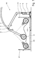
- FIG. 1 shows a roller compactor 100 for compacting waste materials 203.
- a container 200 has a front end wall 201 and a rear end wall 202. The line in the container 200 identifies the upper side of waste materials 203 which are stacked therein.
- a stand 16 of the roller compactor 100 is arranged behind the rear end wall 202 and extends with runners jumping forward to below the bottom of the container 200 in order to improve the support.
- a support arm 10 is connected to the stand 12 via a joint 15.
- a pendulum arm 20 is connected via a joint 11. No actuators are provided between the support arm 10 and the pendulum arm 20, so that the pendulum arm 20 can pivot freely about the joint 11.
- a gear holder element 25 is attached, which contains, among other things, bearing elements and a gear for a roller unit 30 in order to drive a roller 11.
- Lift cylinder is also a here between the tripod 12 and the support arm 10
- Lift cylinder is provided as an actuator in order to be able to raise and lower the support arm 10. With the lifting and lowering of the support arm 10, the joint 11 moves on an arc 17.
- the invention relates in particular to the pendulum arm 20 together with the roller unit 30 of the roller compactor 100.
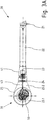
- the pendulum arm 20 is in Figure 2 shown separately, namely in a view from above onto a central axis 36 of the roller unit 30.
- the pendulum arm 20 comprises two outer carrier profiles 22 which connect to a common head element 26 which has bearing mounts 21 for forming the pivot bearing 11.
- a common foot element 23 which is hollow and receives an electric motor 41 inside.
- the foot element 23 has a connecting flange 24 on the side facing away from the carrier profiles 22, to which the gear holder element 25 is fastened.
- the pendulum arm 20 has a motor unit 40 which, in addition to the electric motor 41, has a compensating clutch 42, a drive shaft 43 and an in Fig. 2 has invisible plug coupling.
- the roller unit 30 comprises the roller bodies 31, 32, which are fastened to flanges 33, 57 of an output shaft 25.
- the two roller bodies 31, 32 together form an almost continuous cylinder body, in the Inside, part of the gear holder element 25 is received, to which the gear 50 is in turn attached.
- Figure 3A shows the pendulum arm 20 with the roller unit 30 in a side view. From this, in particular, the contour of the gear holder element 25 with an annular disk-shaped area 25. 1, which extends around a central recess to which the gear 50 is attached, becomes clear.
- the annular disk-shaped area 25.1 runs towards the pendulum arm 20 in a trapezoidal area 25.2.
- the gear holder element 25 is in Figure 6 shown individually in a perspective view.
- the annular disk-shaped area 25.1 and the trapezoidal area 25.2 are formed from two sheet metal blanks 25.10, 25.11, of which the sheet metal blank 25.11 has a flange for the gearbox and the sheet metal blank 25.11 lying thereon is recessed somewhat further so that the gearbox housing can be attached to the flange unhindered.
- Ring-shaped webs 25.9 are attached to area 25.1 on both sides. These protrude into the inner, hollow part of the roller body in order to cover the gap between the roller body and gear holder element 25.
- the annular disk-shaped area 25.1 includes a recess 25.8 for receiving the gear.
- the recess 25.8 continues in the trapezoidal region 25.2 as a narrow recess 25.7 in which the drive shaft can be received.
- the end of the trapezoidal area 25.2 is closed by a flange plate 25.4, which contains a recess 25.5 for the passage of the drive shaft.
- Reinforcing plates 25.3 serve to reinforce the gear holder element 25 against bending forces which act between the pendulum arm 12 and the roller unit 30.
- FIG 3B is off as an enlargement Figure 3 the roller unit 30 with the gear 50 is shown in detail.
- the drive shaft 43 runs from the motor 41 via a compensating coupling 42, such as a claw coupling, to a plug-in coupling 44. If the roller unit 30 has to be replaced for maintenance purposes, only a mechanical connection is required be solved on the flange 24. The roller unit 30 can then be completely removed from the pendulum arm 20 without the motor 41 or control and / or power supply lines leading there having to be released. Nothing needs to be removed from the roller unit 50 either. In the later assembly, only the end of the drive shaft 43 has to be inserted into the plug-in coupling 44 on the gear 50 and the connection on the flange 24 must be restored.
- the gear 50 receives the output shaft 57 and also has bearings therefor, so that the output shaft 57 and the gear 50 form a unit.
- the satellite-shaped arrangement of the gear stages 51, 52, 53 around the central output shaft 57 is characteristic of the preferred embodiment of the invention.
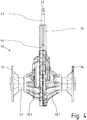
- Figure 4 shows a side view of a gear 50.
- the gear 50 has two housing halves 58.1, 58.2 which are screwed together. The parting plane between them coincides with the central axis of the drive shaft 43.
- the dashed lines indicate the position of the gear holder element 25, which essentially consists of two sheet metal blanks, the connection plane of which corresponds to the said parting plane and the central axis.
- Parts of the output shaft 57 protrude from the housing of the transmission 50 on both sides.
- the ends of each are provided with a flange 33, 34, to which the roller bodies are later attached.
- FIG. 5 shows a detail of the plug-in coupling 44 on the transmission 50.
- a short entry shaft 59 protrudes from the top of the transmission housing.
- the plug-in coupling 44 has at least one form-locking means such as a key 44.1 for torque transmission to the shafts 43, 59. Otherwise, only sealing rings are provided in the plug-in coupling 44 in order to avoid the ingress of dirt. Appropriate shaping at the ends of the shafts 43, 59 prevents an excessive axial Change of position of the plug coupling.
- a positive or non-positive locking between the ends of the shafts 43, 59 and the plug-in coupling 44 in the axial direction is not provided in order to facilitate the assembly and disassembly of the roller unit 30 on or from the pendulum arm 20.
Landscapes
- Engineering & Computer Science (AREA)
- Mechanical Engineering (AREA)
- Environmental & Geological Engineering (AREA)
- Gear Transmission (AREA)
- Road Paving Machines (AREA)
- Refuse Receptacles (AREA)
- Refuse Collection And Transfer (AREA)
Applications Claiming Priority (1)
| Application Number | Priority Date | Filing Date | Title |
|---|---|---|---|
| DE102019100001.7A DE102019100001A1 (de) | 2019-01-01 | 2019-01-01 | Pendelarm für einen Walzenverdichter zum Verdichten von Abfallstoffen in einem oben offenen Container |
Publications (2)
| Publication Number | Publication Date |
|---|---|
| EP3677351A1 true EP3677351A1 (fr) | 2020-07-08 |
| EP3677351B1 EP3677351B1 (fr) | 2022-12-14 |
Family
ID=69063640
Family Applications (1)
| Application Number | Title | Priority Date | Filing Date |
|---|---|---|---|
| EP19220033.5A Active EP3677351B1 (fr) | 2019-01-01 | 2019-12-30 | Bras de pendule pour un compresseur à rouleaux permettant de comprimer des déchets dans un conteneur ouvert |
Country Status (6)
| Country | Link |
|---|---|
| EP (1) | EP3677351B1 (fr) |
| DE (1) | DE102019100001A1 (fr) |
| DK (1) | DK3677351T3 (fr) |
| ES (1) | ES2938686T3 (fr) |
| FI (1) | FI3677351T3 (fr) |
| PL (1) | PL3677351T3 (fr) |
Cited By (1)
| Publication number | Priority date | Publication date | Assignee | Title |
|---|---|---|---|---|
| EP4403345A1 (fr) * | 2023-01-19 | 2024-07-24 | Heinz Bergmann oHG Maschinen für die Abfallwirtschaft | Bras oscillant pour un compresseur à rouleaux pour comprimer des déchets |
Citations (4)
| Publication number | Priority date | Publication date | Assignee | Title |
|---|---|---|---|---|
| DE3023508C1 (de) | 1980-06-24 | 1981-12-10 | Heinz 4474 Lathen Bergmann | Vorrichtung zum Verdichten von aus Verpackungsmaterial und leicht preßbaren Abfällen bestehendem Müll |
| EP0106268A1 (fr) * | 1982-10-15 | 1984-04-25 | Heinz Bergmann | Dispositif pour compacter des immondices composés de matériel d'emballage et des déchets facile à presser |
| DE202011000241U1 (de) | 2011-02-01 | 2011-06-01 | Heinz Bergmann Maschine für die Abfallwirtschaft e.K., 49762 | Walzenverdichtervorrichtung zum Verdichten von Abfällen und Wertstoffen |
| EP2808161A1 (fr) * | 2013-05-31 | 2014-12-03 | Heinz Bergmann e.Kfm. Maschinen für die Abfallwirtschaft | Dispositif de compacteur à rouleaux pour le compactage de déchets et de matières recyclables |
-
2019
- 2019-01-01 DE DE102019100001.7A patent/DE102019100001A1/de not_active Withdrawn
- 2019-12-30 ES ES19220033T patent/ES2938686T3/es active Active
- 2019-12-30 DK DK19220033.5T patent/DK3677351T3/da active
- 2019-12-30 PL PL19220033.5T patent/PL3677351T3/pl unknown
- 2019-12-30 FI FIEP19220033.5T patent/FI3677351T3/fi active
- 2019-12-30 EP EP19220033.5A patent/EP3677351B1/fr active Active
Patent Citations (4)
| Publication number | Priority date | Publication date | Assignee | Title |
|---|---|---|---|---|
| DE3023508C1 (de) | 1980-06-24 | 1981-12-10 | Heinz 4474 Lathen Bergmann | Vorrichtung zum Verdichten von aus Verpackungsmaterial und leicht preßbaren Abfällen bestehendem Müll |
| EP0106268A1 (fr) * | 1982-10-15 | 1984-04-25 | Heinz Bergmann | Dispositif pour compacter des immondices composés de matériel d'emballage et des déchets facile à presser |
| DE202011000241U1 (de) | 2011-02-01 | 2011-06-01 | Heinz Bergmann Maschine für die Abfallwirtschaft e.K., 49762 | Walzenverdichtervorrichtung zum Verdichten von Abfällen und Wertstoffen |
| EP2808161A1 (fr) * | 2013-05-31 | 2014-12-03 | Heinz Bergmann e.Kfm. Maschinen für die Abfallwirtschaft | Dispositif de compacteur à rouleaux pour le compactage de déchets et de matières recyclables |
Cited By (1)
| Publication number | Priority date | Publication date | Assignee | Title |
|---|---|---|---|---|
| EP4403345A1 (fr) * | 2023-01-19 | 2024-07-24 | Heinz Bergmann oHG Maschinen für die Abfallwirtschaft | Bras oscillant pour un compresseur à rouleaux pour comprimer des déchets |
Also Published As
| Publication number | Publication date |
|---|---|
| FI3677351T3 (fi) | 2023-03-19 |
| DK3677351T3 (da) | 2023-02-13 |
| EP3677351B1 (fr) | 2022-12-14 |
| PL3677351T3 (pl) | 2023-02-06 |
| ES2938686T3 (es) | 2023-04-13 |
| DE102019100001A1 (de) | 2020-07-02 |
Similar Documents
| Publication | Publication Date | Title |
|---|---|---|
| EP2613931B1 (fr) | Vis transporteuse | |
| EP0443060B1 (fr) | Unité de galets de propulsion | |
| AT511833A4 (de) | Mastaufbau insbesondere für eine autobetonpumpe | |
| EP3775535B1 (fr) | Palier à roulement de grande dimension | |
| EP3405699B1 (fr) | Actionneur comportant une chaîne semi-rigide | |
| DE3330204A1 (de) | Stirnradgetriebe, insbesondere fuer den antrieb eines walzenmantels | |
| EP3677351B1 (fr) | Bras de pendule pour un compresseur à rouleaux permettant de comprimer des déchets dans un conteneur ouvert | |
| DE3728389C2 (fr) | ||
| EP3405698B1 (fr) | Actionneur équipé d'une vis creuse | |
| AT520549B1 (de) | Hydraulischer Drehantrieb | |
| EP1018416B1 (fr) | Calandre pour matières premières dans l'indutrie de la céramique | |
| DE3038587C2 (de) | Antreibbare Walze mit steuerbarer Durchbiegung, insbesondere für Maschinen zur Erzeugung und Verarbeitung von Bahnen aus Papier oder Kunststoff | |
| DE102005021460A1 (de) | Verstelleinrichtung für Kupplungen und Getriebebremsen, insbesondere von Kraftfahrzeugen zum Verstellen eines einen Auflage- und Drehpunkt eines gebogenen Hebels bildenden Auflagerelements | |
| DE3141039C2 (de) | Vorrichtung zum Bewegen stangenförmigen Gutes, wie z.B. Rohre, Wellen und Draht, in Richtung seiner Längsachse, insbesondere als Ein- oder Auszungseinrichtung für Schäl- und/oder Richtmaschinen | |
| EP2329161B1 (fr) | Système de joint de cardan pour un arbre de transmission | |
| EP4403345B1 (fr) | Bras oscillant pour un compresseur à rouleaux pour comprimer des déchets | |
| DE102008058304B4 (de) | Antriebsvorrichtung | |
| DE3804225C2 (fr) | ||
| EP0924338B1 (fr) | Unité d' entraínement avec support de couple mobil pour rouleaux | |
| EP0305549B1 (fr) | Chambre de decalaminage de feuillards avec des poudres abrasives | |
| DE202005011280U1 (de) | Hub-/Schwenkvorrichtung für Ladebordwände und/oder -rampen | |
| EP2139671A1 (fr) | Ensemble vis sans fin de pressage | |
| DE1684037C3 (de) | Beschickungswagen für zur Herstellung keramischer und feuerfester Gegenstände dienende Pressen mit korn- oder pulverförmigen Materialien | |
| DE102005039134A1 (de) | Kupplungs-und Bremsvorrichtung | |
| DE8322412U1 (de) | Aufsteck-Getriebemotor |
Legal Events
| Date | Code | Title | Description |
|---|---|---|---|
| PUAI | Public reference made under article 153(3) epc to a published international application that has entered the european phase |
Free format text: ORIGINAL CODE: 0009012 |
|
| STAA | Information on the status of an ep patent application or granted ep patent |
Free format text: STATUS: THE APPLICATION HAS BEEN PUBLISHED |
|
| AK | Designated contracting states |
Kind code of ref document: A1 Designated state(s): AL AT BE BG CH CY CZ DE DK EE ES FI FR GB GR HR HU IE IS IT LI LT LU LV MC MK MT NL NO PL PT RO RS SE SI SK SM TR |
|
| AX | Request for extension of the european patent |
Extension state: BA ME |
|
| STAA | Information on the status of an ep patent application or granted ep patent |
Free format text: STATUS: REQUEST FOR EXAMINATION WAS MADE |
|
| 17P | Request for examination filed |
Effective date: 20210108 |
|
| RBV | Designated contracting states (corrected) |
Designated state(s): AL AT BE BG CH CY CZ DE DK EE ES FI FR GB GR HR HU IE IS IT LI LT LU LV MC MK MT NL NO PL PT RO RS SE SI SK SM TR |
|
| GRAP | Despatch of communication of intention to grant a patent |
Free format text: ORIGINAL CODE: EPIDOSNIGR1 |
|
| STAA | Information on the status of an ep patent application or granted ep patent |
Free format text: STATUS: GRANT OF PATENT IS INTENDED |
|
| INTG | Intention to grant announced |
Effective date: 20220621 |
|
| GRAS | Grant fee paid |
Free format text: ORIGINAL CODE: EPIDOSNIGR3 |
|
| GRAA | (expected) grant |
Free format text: ORIGINAL CODE: 0009210 |
|
| STAA | Information on the status of an ep patent application or granted ep patent |
Free format text: STATUS: THE PATENT HAS BEEN GRANTED |
|
| AK | Designated contracting states |
Kind code of ref document: B1 Designated state(s): AL AT BE BG CH CY CZ DE DK EE ES FI FR GB GR HR HU IE IS IT LI LT LU LV MC MK MT NL NO PL PT RO RS SE SI SK SM TR |
|
| REG | Reference to a national code |
Ref country code: GB Ref legal event code: FG4D Free format text: NOT ENGLISH |
|
| REG | Reference to a national code |
Ref country code: CH Ref legal event code: EP |
|
| REG | Reference to a national code |
Ref country code: DE Ref legal event code: R082 Ref document number: 502019006520 Country of ref document: DE Representative=s name: TARVENKORN WICKORD & PARTNER PATENTANWAELTE PA, DE Ref country code: DE Ref legal event code: R082 Ref document number: 502019006520 Country of ref document: DE Representative=s name: TARVENKORN & WICKORD PATENTANWAELTE PARTG MBB, DE Ref country code: DE Ref legal event code: R082 Ref document number: 502019006520 Country of ref document: DE Representative=s name: BOEHMERT & BOEHMERT ANWALTSPARTNERSCHAFT MBB -, DE |
|
| REG | Reference to a national code |
Ref country code: DE Ref legal event code: R096 Ref document number: 502019006520 Country of ref document: DE |
|
| REG | Reference to a national code |
Ref country code: IE Ref legal event code: FG4D Free format text: LANGUAGE OF EP DOCUMENT: GERMAN |
|
| REG | Reference to a national code |
Ref country code: AT Ref legal event code: REF Ref document number: 1537367 Country of ref document: AT Kind code of ref document: T Effective date: 20230115 |
|
| REG | Reference to a national code |
Ref country code: NL Ref legal event code: FP |
|
| REG | Reference to a national code |
Ref country code: DK Ref legal event code: T3 Effective date: 20230209 |
|
| REG | Reference to a national code |
Ref country code: SE Ref legal event code: TRGR |
|
| REG | Reference to a national code |
Ref country code: NO Ref legal event code: T2 Effective date: 20221214 |
|
| REG | Reference to a national code |
Ref country code: LT Ref legal event code: MG9D |
|
| REG | Reference to a national code |
Ref country code: ES Ref legal event code: FG2A Ref document number: 2938686 Country of ref document: ES Kind code of ref document: T3 Effective date: 20230413 |
|
| PG25 | Lapsed in a contracting state [announced via postgrant information from national office to epo] |
Ref country code: LT Free format text: LAPSE BECAUSE OF FAILURE TO SUBMIT A TRANSLATION OF THE DESCRIPTION OR TO PAY THE FEE WITHIN THE PRESCRIBED TIME-LIMIT Effective date: 20221214 |
|
| PG25 | Lapsed in a contracting state [announced via postgrant information from national office to epo] |
Ref country code: RS Free format text: LAPSE BECAUSE OF FAILURE TO SUBMIT A TRANSLATION OF THE DESCRIPTION OR TO PAY THE FEE WITHIN THE PRESCRIBED TIME-LIMIT Effective date: 20221214 Ref country code: LV Free format text: LAPSE BECAUSE OF FAILURE TO SUBMIT A TRANSLATION OF THE DESCRIPTION OR TO PAY THE FEE WITHIN THE PRESCRIBED TIME-LIMIT Effective date: 20221214 Ref country code: HR Free format text: LAPSE BECAUSE OF FAILURE TO SUBMIT A TRANSLATION OF THE DESCRIPTION OR TO PAY THE FEE WITHIN THE PRESCRIBED TIME-LIMIT Effective date: 20221214 Ref country code: GR Free format text: LAPSE BECAUSE OF FAILURE TO SUBMIT A TRANSLATION OF THE DESCRIPTION OR TO PAY THE FEE WITHIN THE PRESCRIBED TIME-LIMIT Effective date: 20230315 |
|
| P01 | Opt-out of the competence of the unified patent court (upc) registered |
Effective date: 20230530 |
|
| PG25 | Lapsed in a contracting state [announced via postgrant information from national office to epo] |
Ref country code: SM Free format text: LAPSE BECAUSE OF FAILURE TO SUBMIT A TRANSLATION OF THE DESCRIPTION OR TO PAY THE FEE WITHIN THE PRESCRIBED TIME-LIMIT Effective date: 20221214 Ref country code: RO Free format text: LAPSE BECAUSE OF FAILURE TO SUBMIT A TRANSLATION OF THE DESCRIPTION OR TO PAY THE FEE WITHIN THE PRESCRIBED TIME-LIMIT Effective date: 20221214 Ref country code: PT Free format text: LAPSE BECAUSE OF FAILURE TO SUBMIT A TRANSLATION OF THE DESCRIPTION OR TO PAY THE FEE WITHIN THE PRESCRIBED TIME-LIMIT Effective date: 20230414 Ref country code: EE Free format text: LAPSE BECAUSE OF FAILURE TO SUBMIT A TRANSLATION OF THE DESCRIPTION OR TO PAY THE FEE WITHIN THE PRESCRIBED TIME-LIMIT Effective date: 20221214 Ref country code: CZ Free format text: LAPSE BECAUSE OF FAILURE TO SUBMIT A TRANSLATION OF THE DESCRIPTION OR TO PAY THE FEE WITHIN THE PRESCRIBED TIME-LIMIT Effective date: 20221214 |
|
| PG25 | Lapsed in a contracting state [announced via postgrant information from national office to epo] |
Ref country code: SK Free format text: LAPSE BECAUSE OF FAILURE TO SUBMIT A TRANSLATION OF THE DESCRIPTION OR TO PAY THE FEE WITHIN THE PRESCRIBED TIME-LIMIT Effective date: 20221214 Ref country code: LU Free format text: LAPSE BECAUSE OF NON-PAYMENT OF DUE FEES Effective date: 20221230 Ref country code: IS Free format text: LAPSE BECAUSE OF FAILURE TO SUBMIT A TRANSLATION OF THE DESCRIPTION OR TO PAY THE FEE WITHIN THE PRESCRIBED TIME-LIMIT Effective date: 20230414 Ref country code: AL Free format text: LAPSE BECAUSE OF FAILURE TO SUBMIT A TRANSLATION OF THE DESCRIPTION OR TO PAY THE FEE WITHIN THE PRESCRIBED TIME-LIMIT Effective date: 20221214 |
|
| REG | Reference to a national code |
Ref country code: DE Ref legal event code: R097 Ref document number: 502019006520 Country of ref document: DE |
|
| PG25 | Lapsed in a contracting state [announced via postgrant information from national office to epo] |
Ref country code: MC Free format text: LAPSE BECAUSE OF FAILURE TO SUBMIT A TRANSLATION OF THE DESCRIPTION OR TO PAY THE FEE WITHIN THE PRESCRIBED TIME-LIMIT Effective date: 20221214 |
|
| PLBE | No opposition filed within time limit |
Free format text: ORIGINAL CODE: 0009261 |
|
| STAA | Information on the status of an ep patent application or granted ep patent |
Free format text: STATUS: NO OPPOSITION FILED WITHIN TIME LIMIT |
|
| PG25 | Lapsed in a contracting state [announced via postgrant information from national office to epo] |
Ref country code: IE Free format text: LAPSE BECAUSE OF NON-PAYMENT OF DUE FEES Effective date: 20221230 |
|
| 26N | No opposition filed |
Effective date: 20230915 |
|
| PG25 | Lapsed in a contracting state [announced via postgrant information from national office to epo] |
Ref country code: SI Free format text: LAPSE BECAUSE OF FAILURE TO SUBMIT A TRANSLATION OF THE DESCRIPTION OR TO PAY THE FEE WITHIN THE PRESCRIBED TIME-LIMIT Effective date: 20221214 |
|
| PG25 | Lapsed in a contracting state [announced via postgrant information from national office to epo] |
Ref country code: HU Free format text: LAPSE BECAUSE OF FAILURE TO SUBMIT A TRANSLATION OF THE DESCRIPTION OR TO PAY THE FEE WITHIN THE PRESCRIBED TIME-LIMIT; INVALID AB INITIO Effective date: 20191230 |
|
| REG | Reference to a national code |
Ref country code: DE Ref legal event code: R082 Ref document number: 502019006520 Country of ref document: DE Representative=s name: BOEHMERT & BOEHMERT ANWALTSPARTNERSCHAFT MBB -, DE |
|
| PG25 | Lapsed in a contracting state [announced via postgrant information from national office to epo] |
Ref country code: CY Free format text: LAPSE BECAUSE OF FAILURE TO SUBMIT A TRANSLATION OF THE DESCRIPTION OR TO PAY THE FEE WITHIN THE PRESCRIBED TIME-LIMIT Effective date: 20221214 |
|
| PG25 | Lapsed in a contracting state [announced via postgrant information from national office to epo] |
Ref country code: MK Free format text: LAPSE BECAUSE OF FAILURE TO SUBMIT A TRANSLATION OF THE DESCRIPTION OR TO PAY THE FEE WITHIN THE PRESCRIBED TIME-LIMIT Effective date: 20221214 Ref country code: IT Free format text: LAPSE BECAUSE OF FAILURE TO SUBMIT A TRANSLATION OF THE DESCRIPTION OR TO PAY THE FEE WITHIN THE PRESCRIBED TIME-LIMIT Effective date: 20221214 |
|
| PG25 | Lapsed in a contracting state [announced via postgrant information from national office to epo] |
Ref country code: TR Free format text: LAPSE BECAUSE OF FAILURE TO SUBMIT A TRANSLATION OF THE DESCRIPTION OR TO PAY THE FEE WITHIN THE PRESCRIBED TIME-LIMIT Effective date: 20221214 |
|
| PG25 | Lapsed in a contracting state [announced via postgrant information from national office to epo] |
Ref country code: BG Free format text: LAPSE BECAUSE OF FAILURE TO SUBMIT A TRANSLATION OF THE DESCRIPTION OR TO PAY THE FEE WITHIN THE PRESCRIBED TIME-LIMIT Effective date: 20221214 |
|
| PG25 | Lapsed in a contracting state [announced via postgrant information from national office to epo] |
Ref country code: MT Free format text: LAPSE BECAUSE OF FAILURE TO SUBMIT A TRANSLATION OF THE DESCRIPTION OR TO PAY THE FEE WITHIN THE PRESCRIBED TIME-LIMIT Effective date: 20221214 |
|
| REG | Reference to a national code |
Ref country code: CH Ref legal event code: U11 Free format text: ST27 STATUS EVENT CODE: U-0-0-U10-U11 (AS PROVIDED BY THE NATIONAL OFFICE) Effective date: 20260101 |
|
| PGFP | Annual fee paid to national office [announced via postgrant information from national office to epo] |
Ref country code: GB Payment date: 20251218 Year of fee payment: 7 |
|
| PGFP | Annual fee paid to national office [announced via postgrant information from national office to epo] |
Ref country code: NO Payment date: 20251216 Year of fee payment: 7 |
|
| PGFP | Annual fee paid to national office [announced via postgrant information from national office to epo] |
Ref country code: AT Payment date: 20251215 Year of fee payment: 7 |
|
| PGFP | Annual fee paid to national office [announced via postgrant information from national office to epo] |
Ref country code: FI Payment date: 20251216 Year of fee payment: 7 Ref country code: DK Payment date: 20251217 Year of fee payment: 7 |
|
| PGFP | Annual fee paid to national office [announced via postgrant information from national office to epo] |
Ref country code: FR Payment date: 20251218 Year of fee payment: 7 Ref country code: NL Payment date: 20251217 Year of fee payment: 7 |
|
| PGFP | Annual fee paid to national office [announced via postgrant information from national office to epo] |
Ref country code: BE Payment date: 20251223 Year of fee payment: 7 |
|
| PGFP | Annual fee paid to national office [announced via postgrant information from national office to epo] |
Ref country code: SE Payment date: 20251217 Year of fee payment: 7 |
|
| PGFP | Annual fee paid to national office [announced via postgrant information from national office to epo] |
Ref country code: PL Payment date: 20251219 Year of fee payment: 7 |
|
| PGFP | Annual fee paid to national office [announced via postgrant information from national office to epo] |
Ref country code: ES Payment date: 20260119 Year of fee payment: 7 |
|
| PGFP | Annual fee paid to national office [announced via postgrant information from national office to epo] |
Ref country code: DE Payment date: 20251222 Year of fee payment: 7 |
|
| PGFP | Annual fee paid to national office [announced via postgrant information from national office to epo] |
Ref country code: CH Payment date: 20260101 Year of fee payment: 7 |