EP3677351B1 - Pendelarm fuer einen walzenverdichter zum verdichten von abfallstoffen in einem oben offenen container - Google Patents
Pendelarm fuer einen walzenverdichter zum verdichten von abfallstoffen in einem oben offenen container Download PDFInfo
- Publication number
- EP3677351B1 EP3677351B1 EP19220033.5A EP19220033A EP3677351B1 EP 3677351 B1 EP3677351 B1 EP 3677351B1 EP 19220033 A EP19220033 A EP 19220033A EP 3677351 B1 EP3677351 B1 EP 3677351B1
- Authority
- EP
- European Patent Office
- Prior art keywords
- pendulum arm
- roller
- gearbox
- disposed
- gear
- Prior art date
- Legal status (The legal status is an assumption and is not a legal conclusion. Google has not performed a legal analysis and makes no representation as to the accuracy of the status listed.)
- Active
Links
Images


Classifications
-
- B—PERFORMING OPERATIONS; TRANSPORTING
- B09—DISPOSAL OF SOLID WASTE; RECLAMATION OF CONTAMINATED SOIL
- B09B—DISPOSAL OF SOLID WASTE NOT OTHERWISE PROVIDED FOR
- B09B1/00—Dumping solid waste
-
- B—PERFORMING OPERATIONS; TRANSPORTING
- B30—PRESSES
- B30B—PRESSES IN GENERAL
- B30B9/00—Presses specially adapted for particular purposes
- B30B9/30—Presses specially adapted for particular purposes for baling; Compression boxes therefor
- B30B9/3082—Presses specially adapted for particular purposes for baling; Compression boxes therefor with compression means other than rams performing a rectilinear movement
Definitions
- the invention relates to a pendulum arm for a roller compactor for compacting waste materials in an open-topped container, having the features of the preamble of claim 1.
- EP 0 106 268 A1 shows a refuse compacting device in which an approximately cylindrical container is provided, in the center of which an axis is arranged.
- a driven roller body is arranged perpendicularly to the axis. It is driven in rotation and runs around the axis on a circular path in the container.
- roller compactor was by the applicant for the first time in the DE 30 23 508 C1 described.
- a roller which is guided at the end of an articulated pendulum arm, effects the compaction.
- the rotation of the roller leads to the shifting of the near-surface layers of the waste in the container and enables their movement in the longitudinal direction of the container.
- the roller compactor is particularly suitable for dry waste with large cavities such as bulky waste or wooden crates.
- the capacity of the container is significantly increased compared to uncompacted waste.
- the support arm is positioned on a tripod outside of the container in order to be able to use the entire container volume for waste.
- a two-part articulated arm is provided.
- the first part of the articulated arm which is connected to the tripod, can be raised via an actuator, such as a hydraulic cylinder, in order to lift the roller out of the container.
- a pendulum arm is connected to its other end via a swivel joint, at the end of which the rotatable roller is in turn mounted. This causes the compaction solely due to its own weight, i.e. without any contact pressure from the arm.
- the roller bodies have been driven by a hydraulic motor. To do this, a powerful hydraulic pump must be set up next to the stationary part of the roller compactor.
- a hydraulic line is routed from there via the two-part articulated arm, of which the pendulum arm forms one end section, to the hydraulic motor inside the roller unit. Due to the great length of the hydraulic supply and discharge lines, a large volume of hydraulic fluid has to be kept in stock and circulated during operation. When the direction of rotation of the roller bodies is reversed, throttle valves are required to slow down the overrun. Due to the large moments of inertia that emanate from the roller bodies, they are also heavily loaded. The hydraulic fluid heats up accordingly, which reduces the viscosity and the power that can be brought into the waste dump via the roller unit decreases. Therefore, either an additional temperature control in the oil circuit must be provided, or regular interruptions in operation are required for cooling.
- the noise of the hydraulic unit has a disruptive effect.
- the assembly or disassembly of the roller unit is time-consuming because, among other things, the oil circuit must be emptied or filled before the hydraulic lines can be removed and the mechanical connection of the roller unit can be released.
- the object of the invention is therefore to improve a pendulum arm of the type mentioned at the outset in such a way that the disadvantages mentioned when driving the roller are eliminated.
- This pendulum arm is a self-sufficient unit so that it can be used to retrofit existing roller compactors with a pendulum arm. Together with a tripod and an at least one-piece support arm, it forms a complete roller compactor.
- the advantage consists in particular in the use of an electric drive, with the motor being arranged in the pendulum arm and a gear mechanism for reducing the speed being designed in the roller unit. Since an electric motor of the required power class of around 3 to 7.5 kW is designed for a speed of around 1500 rpm, but the roller body runs very slowly at around 6 to 15 rpm, a high reduction in the gear is required.
- the conversion to an electric drive has the advantage that only one electric control and supply line needs to be routed through the articulated arm to the roller, which alone has a smaller cross-section than one of the two hydraulic lines in the prior art.
- the speed of the roller can be adjusted during operation via a frequency converter.
- the after-running of the roller bodies when the drive is switched off is already reduced by the gearbox.
- the electric motor itself can be braked in a known manner. Due to the tight coupling of The current speed as well as the after-running of the roller body can be easily recorded in the control of the electric motor and gearbox without the need for speed sensors.
- the special challenge when converting a roller unit for a roller compactor is that this can only have a very flat gear holder element, which is to be arranged between the roller bodies and can therefore hardly be more than twice the sheet metal thickness.
- the gear holder element is designed to be as narrow as possible so that the interruption between the essentially cylindrical roller bodies - and thus the proportion of the peripheral surface over which the roller compactor cannot act on the waste - is as small as possible.
- a drive and gear unit extending radially to the outside of the roller and—seen from the outside—arranged axially between the roller bodies would be too wide and would lead to disruptions in waste processing because waste could not be collected in the non-rotating area between the rollers.
- the invention provides that apart from the narrow marginal sections of the gear holder element, which must protrude between the roller bodies in order to establish a connection to the pendulum arm, all parts of the gear are accommodated within the respective cavity of the adjacent roller bodies. These include the output shaft, the bearings for it and the flanges to which the roller bodies are attached. There is not enough space left inside the cavity of the roller body to accommodate a conventional electric motor with a flange-mounted gear.
- a specific requirement for a pendulum arm for a symmetrically constructed roller compactor with roller bodies on either side of the gear holder element is that the mass distribution be balanced with respect to an axis passing through the gear holder element got to. This is because the pendulum arm, hanging freely on the support arm, only works via the rotation of the roller. Thus, no lateral supporting forces can be applied via the articulated arm, of which the pendulum arm forms a part. Improper mass distribution in the roller unit results in lateral bending moment loading of the pivot joint between the pendulum arm and the support arm, which cannot be designed for such loads without completely changing the basic design of the roller compactor.
- the solution according to the invention provides for arranging the electric motor not in the roller unit but in the pendulum arm, namely axially parallel to or even aligned with its central axis, and also as low as possible on the pendulum arm.
- the gear is arranged separately from the motor within at least one cavity in the roller bodies and forms a unit with the gear holder element that is also balanced in terms of mass distribution.
- the invention provides for the transmission to be fastened to a flange which extends around a central recess in the transmission holder element.
- the gear is thus positioned exactly in the center of the roller unit.
- the drive power is preferably transmitted between the engine and the transmission via a drive shaft.
- the drive-side torque is rather low, so that the drive shaft can be made so thin in particular that it can be guided in a recess in the flat part of the gear holder element without protruding laterally out of it.
- This guidance of the drive shaft applies in particular to the section of the Gear holder element between the end of the pendulum arm and the entrance to the roller unit between the roller bodies.
- a first gear wheel is connected directly to the continuous output shaft, which passes through the transmission and the transmission holder element, namely the spur gear and the pinion engaging there are positioned between the bearings of the output shaft.
- a pair of bevel gears is preferably arranged in the radial edge area of the transmission housing.
- the rotation of the input shaft is already deflected by 90° there, so that all subsequent gear stages in the gearbox can be aligned parallel to the axis of the output shaft.
- the gear stages preferably each have a gear wheel and a pinion on a common shaft. Gear and pinion are each alternately positioned on different sides of the median plane defined by the gear holder member.
- the preferred embodiment of the invention provides for a satellite-shaped arrangement of the gear stages, ie they are arranged next to one another in the annular space between the outer circumference of the output shaft and the inner circumference of the cavity in the roller bodies.
- “Side by side” here does not mean the arrangement in a linear manner, but - seen in the side view of the transmission - along an arcuate or otherwise curved path.
- this arrangement extends between the first transmission stage, which acts directly on the output shaft, and the inlet opening on the transmission housing for the drive shaft over approximately 60° to 80°.
- FIG. 12 shows a roller compactor 100 for compacting waste materials 203.
- a container 200 has a front end wall 201 and a rear end wall 202. The line in container 200 indicates the top of waste materials 203 stacked therein.
- a tripod 16 of the roller compactor 100 is arranged behind the rear end wall 202, which, with skids jumping forward, reaches under the floor of the container 200 in order to improve the support.
- a support arm 10 is connected to the stand 12 via a joint 15 .
- At the upper end of the support arm 10 is A pendulum arm 20 is connected via a joint 11 . No actuators are provided between the support arm 10 and the pendulum arm 20 so that the pendulum arm 20 can pivot freely about the joint 11 .
- a gear holder element which contains, among other things, bearing elements and a gear for a roller unit 30 in order to drive a roller 31 .
- a lifting cylinder is provided as an actuator between the stand 12 and the support arm 10 in order to be able to raise and lower the support arm 10 . With the raising and lowering of the support arm 10, the joint 11 moves on a path 17 in the form of a circular arc.
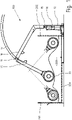
- FIG 1 the end of the pendulum arm 20 with the roller unit 30 is shown again in the vicinity of the end walls 201, 202. These are the end positions that the roller unit 30 can reach by the support arm 10 moving relative to the stand 16, as a result of which the joint axis 11 is moved on the circular path 17.
- No pressing force is exerted via the support arm 10, ie the compaction of the waste materials 203 in the container 20 takes place solely due to the rotation and the mass of the roller unit 30 and the sharp-edged web elements attached to the outer shell of the rollers for conveying and breaking up the waste materials.
- the invention relates in particular to the pendulum arm 20 together with the roller unit 30 of the roller compactor 100.
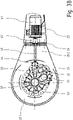
- the pendulum arm 20 is in figure 2 shown separately, namely in a top view of a central axis 36 of the roller unit 30.
- the pendulum arm 20 comprises two outer support profiles 22 which connect to a common head element 26 which has bearing mounts 21 for forming the pivot bearing 11.
- a common base element 23 which is hollow and accommodates an electric motor 41 on the inside.
- the foot element 23 On the side facing away from the carrier profiles 22, the foot element 23 has a connecting flange 24, to which the gear holder element 25 is fastened.
- the pendulum arm 20 has a motor unit 40 which, in addition to the electric motor 41, has a compensating clutch 42, a drive shaft 43 and an in 2 has a non-visible plug-in coupling.
- the roller unit 30 comprises the roller bodies 31, 32 which are fastened to flanges 33, 34 of an output shaft 57.
- the two roller bodies 31, 32 together form an almost uninterrupted cylindrical body, inside which part of the gear holder element 25 is accommodated, to which in turn the gear 50 is fastened.
- Figure 3A shows the pendulum arm 20 with the roller unit 30 in a side view.
- the area 25.1 in the form of an annular disk runs out towards the pendulum arm 20 in a trapezoidal area 25.2.
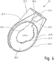
- the gear holder element 25 is in figure 6 shown individually in a perspective view.
- the annular disk-shaped area 25.1 and the trapezoidal area 25.2 are formed from two sheet metal blanks 25.10, 25.11, of which the sheet metal blank 25.11 has a flange for the gear and the sheet metal blank 25.10 lying against it is recessed a little further in order to be able to attach the gear housing unhindered to the flange.
- Ring-shaped webs 25.9 are attached on both sides to area 25.1. These protrude into the inner, hollow part of the roller body in order to cover the gap between the roller body and the gear holder element 25 .
- the area 25.1 in the form of an annular disk encloses a recess 25.8 for accommodating the gear.
- the recess 25.8 continues in the trapezoidal area 25.2 as a narrow recess 25.7, in which the drive shaft can be accommodated.
- the end of the trapezoidal area 25.2 is closed off by a flange plate 25.4, which contains a recess 25.5 for the passage of the drive shaft.
- Reinforcing plates 25.3 are used for Reinforcement of the gear holder element 25 against bending forces acting between the pendulum arm 12 and the roller unit 30.
- FIG 3B is off as magnification figure 3 the roller unit 30 with the gear 50 is shown in detail.
- the drive shaft 43 runs from the motor 41 via a compensating coupling 42, such as a claw coupling, to a plug-in coupling 44. If the roller unit 30 has to be replaced for maintenance purposes, only a mechanical connection on the flange 24 needs to be released. The roller unit 30 can then be removed completely from the pendulum arm 20 without the motor 41 or the control and/or energy supply lines leading there having to be detached. Little needs to be removed from the roller unit 50 either. During subsequent assembly, only the end of the drive shaft 43 has to be reinserted with a precise fit into the plug-in coupling 44 on the transmission 50 and the connection on the flange 24 restored.
- a compensating coupling 42 such as a claw coupling
- the gear 50 accommodates the output shaft 57 and also has bearings for it, so that the output shaft 57 and the gear 50 form a unit.
- On the outside of the housing of the gear 50 a total of three gear stages 51, 52, 53 can be seen from the outside due to the maintenance cover fitted there.
- the satellite-shaped arrangement of the gear stages 51, 52, 53 around the central output shaft 57 is characteristic of the preferred embodiment of the invention.
- figure 4 shows a side view of a gear 50.
- the gear 50 has two housing halves 58.1, 58.2 which are screwed together. The parting plane between them coincides with the central axis of the drive shaft 43 .
- the dashed lines indicate the position of the gear holder element 25, which essentially consists of two sheet metal blanks, the connecting plane of which coincides with the said parting plane and the central axis.
- Parts of the output shaft 57 protrude from the housing of the transmission 50 on both sides. The ends of which are each provided with a flange 33, 34 to which the roller bodies are later attached.
- FIG. 5 shows the plug-in coupling 44 on the transmission 50 in a detail.
- a short input shaft 59 protrudes from the top of the transmission housing.
- the plug-in coupling 44 has at least one form-fitting means, such as a feather key 44.1. Otherwise only sealing rings are provided in the plug-in coupling 44 in order to prevent the ingress of dirt. Appropriate shaping at the ends of the shafts 43, 59 prevents the plug-in coupling from changing its axial position too far.
- a positive or non-positive securing between the ends of the shafts 43, 59 and the plug-in coupling 44 in the axial direction is not provided, however, in order to facilitate the assembly and disassembly of the roller unit 30 on or from the pendulum arm 20.
Landscapes
- Engineering & Computer Science (AREA)
- Mechanical Engineering (AREA)
- Environmental & Geological Engineering (AREA)
- Gear Transmission (AREA)
- Road Paving Machines (AREA)
- Refuse Receptacles (AREA)
- Refuse Collection And Transfer (AREA)
Applications Claiming Priority (1)
| Application Number | Priority Date | Filing Date | Title |
|---|---|---|---|
| DE102019100001.7A DE102019100001A1 (de) | 2019-01-01 | 2019-01-01 | Pendelarm für einen Walzenverdichter zum Verdichten von Abfallstoffen in einem oben offenen Container |
Publications (2)
| Publication Number | Publication Date |
|---|---|
| EP3677351A1 EP3677351A1 (de) | 2020-07-08 |
| EP3677351B1 true EP3677351B1 (de) | 2022-12-14 |
Family
ID=69063640
Family Applications (1)
| Application Number | Title | Priority Date | Filing Date |
|---|---|---|---|
| EP19220033.5A Active EP3677351B1 (de) | 2019-01-01 | 2019-12-30 | Pendelarm fuer einen walzenverdichter zum verdichten von abfallstoffen in einem oben offenen container |
Country Status (6)
| Country | Link |
|---|---|
| EP (1) | EP3677351B1 (da) |
| DE (1) | DE102019100001A1 (da) |
| DK (1) | DK3677351T3 (da) |
| ES (1) | ES2938686T3 (da) |
| FI (1) | FI3677351T3 (da) |
| PL (1) | PL3677351T3 (da) |
Families Citing this family (1)
| Publication number | Priority date | Publication date | Assignee | Title |
|---|---|---|---|---|
| DE102023101271A1 (de) * | 2023-01-19 | 2024-07-25 | Heinz Bergmann Maschinen für die Abfallwirtschaft OHG | Pendelarm für einen Walzenverdichter zum Verdichten von Abfallstoffen |
Family Cites Families (4)
| Publication number | Priority date | Publication date | Assignee | Title |
|---|---|---|---|---|
| DE3023508C1 (de) | 1980-06-24 | 1981-12-10 | Heinz 4474 Lathen Bergmann | Vorrichtung zum Verdichten von aus Verpackungsmaterial und leicht preßbaren Abfällen bestehendem Müll |
| DE3326007A1 (de) * | 1982-10-15 | 1984-04-19 | Heinz 4474 Lathen Bergmann | Vorrichtung zum verdichten von aus verpackungsmaterial und leicht pressbaren abfaellen bestehenden muell |
| DE202011000241U1 (de) | 2011-02-01 | 2011-06-01 | Heinz Bergmann Maschine für die Abfallwirtschaft e.K., 49762 | Walzenverdichtervorrichtung zum Verdichten von Abfällen und Wertstoffen |
| EP2808161B1 (de) * | 2013-05-31 | 2016-09-28 | Heinz Bergmann e.Kfm. Maschinen für die Abfallwirtschaft | Walzenverdichtervorrichtung zum Verdichten von Abfällen und Wertstoffen |
-
2019
- 2019-01-01 DE DE102019100001.7A patent/DE102019100001A1/de not_active Withdrawn
- 2019-12-30 ES ES19220033T patent/ES2938686T3/es active Active
- 2019-12-30 DK DK19220033.5T patent/DK3677351T3/da active
- 2019-12-30 PL PL19220033.5T patent/PL3677351T3/pl unknown
- 2019-12-30 FI FIEP19220033.5T patent/FI3677351T3/fi active
- 2019-12-30 EP EP19220033.5A patent/EP3677351B1/de active Active
Also Published As
| Publication number | Publication date |
|---|---|
| EP3677351A1 (de) | 2020-07-08 |
| FI3677351T3 (fi) | 2023-03-19 |
| DK3677351T3 (da) | 2023-02-13 |
| PL3677351T3 (pl) | 2023-02-06 |
| ES2938686T3 (es) | 2023-04-13 |
| DE102019100001A1 (de) | 2020-07-02 |
Similar Documents
| Publication | Publication Date | Title |
|---|---|---|
| AT511833B1 (de) | Mastaufbau insbesondere für eine autobetonpumpe | |
| EP0443060B1 (de) | Antriebsrolleneinheit | |
| EP3775535B1 (de) | Grosswälzlager | |
| EP1991792B1 (de) | Drehmotor | |
| EP2366908A2 (de) | Aktor | |
| DE102016000568A1 (de) | Aktuator mit einer rückensteifen Kette | |
| DE4206101C2 (de) | Hydromechanisches Antriebssystem | |
| EP3677351B1 (de) | Pendelarm fuer einen walzenverdichter zum verdichten von abfallstoffen in einem oben offenen container | |
| EP1018416B1 (de) | Walzwerk für Rohstoffe für die keramische Industrie | |
| DE3728389A1 (de) | Presswalze, deren durchbiegung einstellbar ist | |
| AT520549B1 (de) | Hydraulischer Drehantrieb | |
| DE3038587A1 (de) | Antreibbare walze mit steuerbarer durchbiegung, insbesondere fuer maschinen zur erzeugung und verarbeitung von bahnen aus papier oder kunststoff | |
| EP4403345B1 (de) | Pendelarm für einen walzenverdichter zum verdichten von abfallstoffen | |
| DE3804225C2 (da) | ||
| EP0808183A1 (de) | Antriebsvorrichtung für ein künstliches herz | |
| DE102008058304B4 (de) | Antriebsvorrichtung | |
| WO2010034501A1 (de) | Kreuzgelenkanordnung für eine gelenkwelle | |
| DE1550769C3 (de) | Hydrostatisches Wechsel- und Wendegetriebe | |
| DE4235345A1 (de) | Laufradanordnung für einen Kran | |
| DE202005011280U1 (de) | Hub-/Schwenkvorrichtung für Ladebordwände und/oder -rampen | |
| EP4012176B1 (de) | Dickstofffördervorrichtung | |
| EP2139671A1 (de) | Pressschnecke | |
| DE19925814C2 (de) | Walzwerk für Rohstoffe für die keramische Industrie | |
| DE102005021029A1 (de) | Axialkolbenmaschine in Schrägscheibenbauweise mit Lagerung des Zylinderblocks auf einem Tragzapfen | |
| DE1684037C3 (de) | Beschickungswagen für zur Herstellung keramischer und feuerfester Gegenstände dienende Pressen mit korn- oder pulverförmigen Materialien |
Legal Events
| Date | Code | Title | Description |
|---|---|---|---|
| PUAI | Public reference made under article 153(3) epc to a published international application that has entered the european phase |
Free format text: ORIGINAL CODE: 0009012 |
|
| STAA | Information on the status of an ep patent application or granted ep patent |
Free format text: STATUS: THE APPLICATION HAS BEEN PUBLISHED |
|
| AK | Designated contracting states |
Kind code of ref document: A1 Designated state(s): AL AT BE BG CH CY CZ DE DK EE ES FI FR GB GR HR HU IE IS IT LI LT LU LV MC MK MT NL NO PL PT RO RS SE SI SK SM TR |
|
| AX | Request for extension of the european patent |
Extension state: BA ME |
|
| STAA | Information on the status of an ep patent application or granted ep patent |
Free format text: STATUS: REQUEST FOR EXAMINATION WAS MADE |
|
| 17P | Request for examination filed |
Effective date: 20210108 |
|
| RBV | Designated contracting states (corrected) |
Designated state(s): AL AT BE BG CH CY CZ DE DK EE ES FI FR GB GR HR HU IE IS IT LI LT LU LV MC MK MT NL NO PL PT RO RS SE SI SK SM TR |
|
| GRAP | Despatch of communication of intention to grant a patent |
Free format text: ORIGINAL CODE: EPIDOSNIGR1 |
|
| STAA | Information on the status of an ep patent application or granted ep patent |
Free format text: STATUS: GRANT OF PATENT IS INTENDED |
|
| INTG | Intention to grant announced |
Effective date: 20220621 |
|
| GRAS | Grant fee paid |
Free format text: ORIGINAL CODE: EPIDOSNIGR3 |
|
| GRAA | (expected) grant |
Free format text: ORIGINAL CODE: 0009210 |
|
| STAA | Information on the status of an ep patent application or granted ep patent |
Free format text: STATUS: THE PATENT HAS BEEN GRANTED |
|
| AK | Designated contracting states |
Kind code of ref document: B1 Designated state(s): AL AT BE BG CH CY CZ DE DK EE ES FI FR GB GR HR HU IE IS IT LI LT LU LV MC MK MT NL NO PL PT RO RS SE SI SK SM TR |
|
| REG | Reference to a national code |
Ref country code: GB Ref legal event code: FG4D Free format text: NOT ENGLISH |
|
| REG | Reference to a national code |
Ref country code: CH Ref legal event code: EP |
|
| REG | Reference to a national code |
Ref country code: DE Ref legal event code: R082 Ref document number: 502019006520 Country of ref document: DE Representative=s name: TARVENKORN WICKORD & PARTNER PATENTANWAELTE PA, DE Ref country code: DE Ref legal event code: R082 Ref document number: 502019006520 Country of ref document: DE Representative=s name: TARVENKORN & WICKORD PATENTANWAELTE PARTG MBB, DE Ref country code: DE Ref legal event code: R082 Ref document number: 502019006520 Country of ref document: DE Representative=s name: BOEHMERT & BOEHMERT ANWALTSPARTNERSCHAFT MBB -, DE |
|
| REG | Reference to a national code |
Ref country code: DE Ref legal event code: R096 Ref document number: 502019006520 Country of ref document: DE |
|
| REG | Reference to a national code |
Ref country code: IE Ref legal event code: FG4D Free format text: LANGUAGE OF EP DOCUMENT: GERMAN |
|
| REG | Reference to a national code |
Ref country code: AT Ref legal event code: REF Ref document number: 1537367 Country of ref document: AT Kind code of ref document: T Effective date: 20230115 |
|
| REG | Reference to a national code |
Ref country code: NL Ref legal event code: FP |
|
| REG | Reference to a national code |
Ref country code: DK Ref legal event code: T3 Effective date: 20230209 |
|
| REG | Reference to a national code |
Ref country code: SE Ref legal event code: TRGR |
|
| REG | Reference to a national code |
Ref country code: NO Ref legal event code: T2 Effective date: 20221214 |
|
| REG | Reference to a national code |
Ref country code: LT Ref legal event code: MG9D |
|
| REG | Reference to a national code |
Ref country code: ES Ref legal event code: FG2A Ref document number: 2938686 Country of ref document: ES Kind code of ref document: T3 Effective date: 20230413 |
|
| PG25 | Lapsed in a contracting state [announced via postgrant information from national office to epo] |
Ref country code: LT Free format text: LAPSE BECAUSE OF FAILURE TO SUBMIT A TRANSLATION OF THE DESCRIPTION OR TO PAY THE FEE WITHIN THE PRESCRIBED TIME-LIMIT Effective date: 20221214 |
|
| PG25 | Lapsed in a contracting state [announced via postgrant information from national office to epo] |
Ref country code: RS Free format text: LAPSE BECAUSE OF FAILURE TO SUBMIT A TRANSLATION OF THE DESCRIPTION OR TO PAY THE FEE WITHIN THE PRESCRIBED TIME-LIMIT Effective date: 20221214 Ref country code: LV Free format text: LAPSE BECAUSE OF FAILURE TO SUBMIT A TRANSLATION OF THE DESCRIPTION OR TO PAY THE FEE WITHIN THE PRESCRIBED TIME-LIMIT Effective date: 20221214 Ref country code: HR Free format text: LAPSE BECAUSE OF FAILURE TO SUBMIT A TRANSLATION OF THE DESCRIPTION OR TO PAY THE FEE WITHIN THE PRESCRIBED TIME-LIMIT Effective date: 20221214 Ref country code: GR Free format text: LAPSE BECAUSE OF FAILURE TO SUBMIT A TRANSLATION OF THE DESCRIPTION OR TO PAY THE FEE WITHIN THE PRESCRIBED TIME-LIMIT Effective date: 20230315 |
|
| P01 | Opt-out of the competence of the unified patent court (upc) registered |
Effective date: 20230530 |
|
| PG25 | Lapsed in a contracting state [announced via postgrant information from national office to epo] |
Ref country code: SM Free format text: LAPSE BECAUSE OF FAILURE TO SUBMIT A TRANSLATION OF THE DESCRIPTION OR TO PAY THE FEE WITHIN THE PRESCRIBED TIME-LIMIT Effective date: 20221214 Ref country code: RO Free format text: LAPSE BECAUSE OF FAILURE TO SUBMIT A TRANSLATION OF THE DESCRIPTION OR TO PAY THE FEE WITHIN THE PRESCRIBED TIME-LIMIT Effective date: 20221214 Ref country code: PT Free format text: LAPSE BECAUSE OF FAILURE TO SUBMIT A TRANSLATION OF THE DESCRIPTION OR TO PAY THE FEE WITHIN THE PRESCRIBED TIME-LIMIT Effective date: 20230414 Ref country code: EE Free format text: LAPSE BECAUSE OF FAILURE TO SUBMIT A TRANSLATION OF THE DESCRIPTION OR TO PAY THE FEE WITHIN THE PRESCRIBED TIME-LIMIT Effective date: 20221214 Ref country code: CZ Free format text: LAPSE BECAUSE OF FAILURE TO SUBMIT A TRANSLATION OF THE DESCRIPTION OR TO PAY THE FEE WITHIN THE PRESCRIBED TIME-LIMIT Effective date: 20221214 |
|
| PG25 | Lapsed in a contracting state [announced via postgrant information from national office to epo] |
Ref country code: SK Free format text: LAPSE BECAUSE OF FAILURE TO SUBMIT A TRANSLATION OF THE DESCRIPTION OR TO PAY THE FEE WITHIN THE PRESCRIBED TIME-LIMIT Effective date: 20221214 Ref country code: LU Free format text: LAPSE BECAUSE OF NON-PAYMENT OF DUE FEES Effective date: 20221230 Ref country code: IS Free format text: LAPSE BECAUSE OF FAILURE TO SUBMIT A TRANSLATION OF THE DESCRIPTION OR TO PAY THE FEE WITHIN THE PRESCRIBED TIME-LIMIT Effective date: 20230414 Ref country code: AL Free format text: LAPSE BECAUSE OF FAILURE TO SUBMIT A TRANSLATION OF THE DESCRIPTION OR TO PAY THE FEE WITHIN THE PRESCRIBED TIME-LIMIT Effective date: 20221214 |
|
| REG | Reference to a national code |
Ref country code: DE Ref legal event code: R097 Ref document number: 502019006520 Country of ref document: DE |
|
| PG25 | Lapsed in a contracting state [announced via postgrant information from national office to epo] |
Ref country code: MC Free format text: LAPSE BECAUSE OF FAILURE TO SUBMIT A TRANSLATION OF THE DESCRIPTION OR TO PAY THE FEE WITHIN THE PRESCRIBED TIME-LIMIT Effective date: 20221214 |
|
| PLBE | No opposition filed within time limit |
Free format text: ORIGINAL CODE: 0009261 |
|
| STAA | Information on the status of an ep patent application or granted ep patent |
Free format text: STATUS: NO OPPOSITION FILED WITHIN TIME LIMIT |
|
| PG25 | Lapsed in a contracting state [announced via postgrant information from national office to epo] |
Ref country code: IE Free format text: LAPSE BECAUSE OF NON-PAYMENT OF DUE FEES Effective date: 20221230 |
|
| 26N | No opposition filed |
Effective date: 20230915 |
|
| PG25 | Lapsed in a contracting state [announced via postgrant information from national office to epo] |
Ref country code: SI Free format text: LAPSE BECAUSE OF FAILURE TO SUBMIT A TRANSLATION OF THE DESCRIPTION OR TO PAY THE FEE WITHIN THE PRESCRIBED TIME-LIMIT Effective date: 20221214 |
|
| PG25 | Lapsed in a contracting state [announced via postgrant information from national office to epo] |
Ref country code: HU Free format text: LAPSE BECAUSE OF FAILURE TO SUBMIT A TRANSLATION OF THE DESCRIPTION OR TO PAY THE FEE WITHIN THE PRESCRIBED TIME-LIMIT; INVALID AB INITIO Effective date: 20191230 |
|
| REG | Reference to a national code |
Ref country code: DE Ref legal event code: R082 Ref document number: 502019006520 Country of ref document: DE Representative=s name: BOEHMERT & BOEHMERT ANWALTSPARTNERSCHAFT MBB -, DE |
|
| PG25 | Lapsed in a contracting state [announced via postgrant information from national office to epo] |
Ref country code: CY Free format text: LAPSE BECAUSE OF FAILURE TO SUBMIT A TRANSLATION OF THE DESCRIPTION OR TO PAY THE FEE WITHIN THE PRESCRIBED TIME-LIMIT Effective date: 20221214 |
|
| PG25 | Lapsed in a contracting state [announced via postgrant information from national office to epo] |
Ref country code: MK Free format text: LAPSE BECAUSE OF FAILURE TO SUBMIT A TRANSLATION OF THE DESCRIPTION OR TO PAY THE FEE WITHIN THE PRESCRIBED TIME-LIMIT Effective date: 20221214 Ref country code: IT Free format text: LAPSE BECAUSE OF FAILURE TO SUBMIT A TRANSLATION OF THE DESCRIPTION OR TO PAY THE FEE WITHIN THE PRESCRIBED TIME-LIMIT Effective date: 20221214 |
|
| PG25 | Lapsed in a contracting state [announced via postgrant information from national office to epo] |
Ref country code: TR Free format text: LAPSE BECAUSE OF FAILURE TO SUBMIT A TRANSLATION OF THE DESCRIPTION OR TO PAY THE FEE WITHIN THE PRESCRIBED TIME-LIMIT Effective date: 20221214 |
|
| PG25 | Lapsed in a contracting state [announced via postgrant information from national office to epo] |
Ref country code: BG Free format text: LAPSE BECAUSE OF FAILURE TO SUBMIT A TRANSLATION OF THE DESCRIPTION OR TO PAY THE FEE WITHIN THE PRESCRIBED TIME-LIMIT Effective date: 20221214 |
|
| PG25 | Lapsed in a contracting state [announced via postgrant information from national office to epo] |
Ref country code: MT Free format text: LAPSE BECAUSE OF FAILURE TO SUBMIT A TRANSLATION OF THE DESCRIPTION OR TO PAY THE FEE WITHIN THE PRESCRIBED TIME-LIMIT Effective date: 20221214 |
|
| REG | Reference to a national code |
Ref country code: CH Ref legal event code: U11 Free format text: ST27 STATUS EVENT CODE: U-0-0-U10-U11 (AS PROVIDED BY THE NATIONAL OFFICE) Effective date: 20260101 |
|
| PGFP | Annual fee paid to national office [announced via postgrant information from national office to epo] |
Ref country code: GB Payment date: 20251218 Year of fee payment: 7 |
|
| PGFP | Annual fee paid to national office [announced via postgrant information from national office to epo] |
Ref country code: NO Payment date: 20251216 Year of fee payment: 7 |
|
| PGFP | Annual fee paid to national office [announced via postgrant information from national office to epo] |
Ref country code: AT Payment date: 20251215 Year of fee payment: 7 |
|
| PGFP | Annual fee paid to national office [announced via postgrant information from national office to epo] |
Ref country code: FI Payment date: 20251216 Year of fee payment: 7 Ref country code: DK Payment date: 20251217 Year of fee payment: 7 |
|
| PGFP | Annual fee paid to national office [announced via postgrant information from national office to epo] |
Ref country code: FR Payment date: 20251218 Year of fee payment: 7 Ref country code: NL Payment date: 20251217 Year of fee payment: 7 |
|
| PGFP | Annual fee paid to national office [announced via postgrant information from national office to epo] |
Ref country code: BE Payment date: 20251223 Year of fee payment: 7 |
|
| PGFP | Annual fee paid to national office [announced via postgrant information from national office to epo] |
Ref country code: SE Payment date: 20251217 Year of fee payment: 7 |
|
| PGFP | Annual fee paid to national office [announced via postgrant information from national office to epo] |
Ref country code: PL Payment date: 20251219 Year of fee payment: 7 |
|
| PGFP | Annual fee paid to national office [announced via postgrant information from national office to epo] |
Ref country code: ES Payment date: 20260119 Year of fee payment: 7 |
|
| PGFP | Annual fee paid to national office [announced via postgrant information from national office to epo] |
Ref country code: DE Payment date: 20251222 Year of fee payment: 7 |
|
| PGFP | Annual fee paid to national office [announced via postgrant information from national office to epo] |
Ref country code: CH Payment date: 20260101 Year of fee payment: 7 |