EP3677360A1 - Federherstellungsmaschine - Google Patents
Federherstellungsmaschine Download PDFInfo
- Publication number
- EP3677360A1 EP3677360A1 EP19211560.8A EP19211560A EP3677360A1 EP 3677360 A1 EP3677360 A1 EP 3677360A1 EP 19211560 A EP19211560 A EP 19211560A EP 3677360 A1 EP3677360 A1 EP 3677360A1
- Authority
- EP
- European Patent Office
- Prior art keywords
- coiling mandrel
- wire
- cutting device
- blade
- spring
- Prior art date
- Legal status (The legal status is an assumption and is not a legal conclusion. Google has not performed a legal analysis and makes no representation as to the accuracy of the status listed.)
- Withdrawn
Links
- 238000004519 manufacturing process Methods 0.000 title claims abstract description 47
- 238000005452 bending Methods 0.000 description 10
- 229910045601 alloy Inorganic materials 0.000 description 7
- 239000000956 alloy Substances 0.000 description 7
- 230000008878 coupling Effects 0.000 description 6
- 238000010168 coupling process Methods 0.000 description 6
- 238000005859 coupling reaction Methods 0.000 description 6
- 229910000997 High-speed steel Inorganic materials 0.000 description 5
- 239000000463 material Substances 0.000 description 4
- 239000012141 concentrate Substances 0.000 description 3
- 230000002452 interceptive effect Effects 0.000 description 3
- 230000004048 modification Effects 0.000 description 3
- 238000012986 modification Methods 0.000 description 3
- 238000010008 shearing Methods 0.000 description 3
- 238000013459 approach Methods 0.000 description 2
- 230000015556 catabolic process Effects 0.000 description 2
- 230000007423 decrease Effects 0.000 description 2
- 230000003247 decreasing effect Effects 0.000 description 2
- 238000006731 degradation reaction Methods 0.000 description 2
- 230000002093 peripheral effect Effects 0.000 description 2
- 229910000831 Steel Inorganic materials 0.000 description 1
- 230000000694 effects Effects 0.000 description 1
- 238000005516 engineering process Methods 0.000 description 1
- 239000007787 solid Substances 0.000 description 1
- 229910001220 stainless steel Inorganic materials 0.000 description 1
- 239000010959 steel Substances 0.000 description 1
- 230000008961 swelling Effects 0.000 description 1
Images


Classifications
-
- B—PERFORMING OPERATIONS; TRANSPORTING
- B21—MECHANICAL METAL-WORKING WITHOUT ESSENTIALLY REMOVING MATERIAL; PUNCHING METAL
- B21F—WORKING OR PROCESSING OF METAL WIRE
- B21F3/00—Coiling wire into particular forms
- B21F3/02—Coiling wire into particular forms helically
- B21F3/04—Coiling wire into particular forms helically externally on a mandrel or the like
-
- B—PERFORMING OPERATIONS; TRANSPORTING
- B21—MECHANICAL METAL-WORKING WITHOUT ESSENTIALLY REMOVING MATERIAL; PUNCHING METAL
- B21F—WORKING OR PROCESSING OF METAL WIRE
- B21F11/00—Cutting wire
- B21F11/005—Cutting wire springs
-
- B—PERFORMING OPERATIONS; TRANSPORTING
- B21—MECHANICAL METAL-WORKING WITHOUT ESSENTIALLY REMOVING MATERIAL; PUNCHING METAL
- B21F—WORKING OR PROCESSING OF METAL WIRE
- B21F3/00—Coiling wire into particular forms
- B21F3/02—Coiling wire into particular forms helically
-
- B—PERFORMING OPERATIONS; TRANSPORTING
- B21—MECHANICAL METAL-WORKING WITHOUT ESSENTIALLY REMOVING MATERIAL; PUNCHING METAL
- B21F—WORKING OR PROCESSING OF METAL WIRE
- B21F35/00—Making springs from wire
Definitions
- the present technology relates to a spring manufacturing machine that manufactures a spring by bending a wire.
- a spring manufacturing machine comprises rollers attached to the front surface of a wall, a bending die, and a cutting device.
- the wire sent out by the rollers is bent by the bending die and is cut by the cutting device, whereby a spring is manufactured.
- the wall of the spring manufacturing machine described in Patent Literature 1 has a cutting tool support wall inclined so as to descend toward the rear, and the cutting tool support wall supports a pair of opposing cutting tools. The pair of cutting tools come into contact with each other and go away from each other in the opposing direction.
- One cutting tool is inserted into the inside of a wound wire (coil) from the rear end portion of the coil, the other cutting tool approaches the wound wire from the outside, and the wire is sandwiched between the two cutting tools to be cut(See patent literature 1).
- Patent Literature 1 Japanese Patent No. 6,403,224
- the gap for inserting the cutting tool is also small, so that it is impossible to insert the one cutting tool into the inside of the wound wire.
- the one cutting tool interferes with a part of the wire other than the part to be cut and this makes it impossible to precisely manufacture the spring.
- the present disclosure is made in view of such circumstances, and an object thereof is to provide a spring manufacturing machine with which even when a spring with a small inside diameter is manufactured, the interference with a part of the wire other than the part to be cut is prevented to make it possible to precisely manufacture the spring.
- a spring manufacturing machine comprises: a coiling mandrel fixed to a wall and protruding from the wall; and a cutting device that has a slider movable in a direction inclined with respect to an axis of the coiling mandrel and a blade attached to the slider, and cuts a bent wire in cooperation with the coiling mandrel.
- the wire is cut by the coiling mandrel fixed to the wall and the cutting device.
- a coiling mandrel with dimensions corresponding to the inside diameter is used. For this reason, even when a spring with a small inside diameter is manufactured, the blade does not interfere with a part of the wire other than the part to be cut.
- the dimensions of the coiling mandrel correspond to a spring with a small inside diameter, for example, a spring where a so-called spring index is not more than 4, a cross-sectional area of the end portion of the coiling mandrel taken along a surface orthogonal to the axis is small, so that if the load acting on the coiling mandrel at the time of cutting concentrates in a radial direction, the coiling mandrel readily breaks.
- the load acting on the coiling mandrel at the time of cutting of the wire acts not only in the radial direction of the coiling mandrel but also in an axial direction thereof. That is, the load acting on the coiling mandrel is dispersed in the radial direction and in the axial direction.
- the coiling mandrel protrudes orthogonally to the wall
- the cutting device is attached to the wall in a posture inclined with respect to the wall, and an angle of inclination of the cutting device with respect to the wall is not more than 30 degrees.
- the spring manufacturing machine according to the present disclosure is provided with an adjustment mechanism that adjusts the posture of the cutting device.
- the wire is cut at an appropriate angle corresponding to the kind of the wire and the spring index by adjusting the posture of the cutting device.
- the blade has a parallel portion parallel to the axis of the coiling mandrel, and the wire is sandwiched between the parallel portion and the coiling mandrel to be cut.
- the cutting device by forming the parallel portion on the blade of the cutting device, when the cutting device is moved along a circular locus to cut the wire, the cutting device is prevented from interfering with the coiling mandrel.
- the wire is cut by the coiling mandrel fixed to the wall and the cutting device.
- a coiling mandrel with dimensions corresponding to the inside diameter is used. For this reason, even when a spring with a small inside diameter is manufactured, the blade does not interfere with a part of the wire other than the part to be cut, so that the spring can be precisely manufactured.
- the cross-sectional area of the end portion of the coiling mandrel taken along the surface orthogonal to the axis is small, so that if the load acting on the coiling mandrel at the time of cutting concentrates in the radial direction, the coiling mandrel readily breaks.
- the load acting on the coiling mandrel at the time of cutting of the wire acts not only in the radial direction of the coiling mandrel but also in the axial direction thereof.
- the load acting on the coiling mandrel is dispersed in the radial direction and in the axial direction.
- the load acting in the radial direction of the coiling mandrel is low, so that the coiling mandrel is difficult to break.
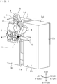
- FIG. 1 is a schematic perspective view of the spring manufacturing machine
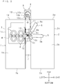
- FIG. 2 is a schematic front view of the spring manufacturing machine.
- the spring manufacturing machine is provided with a first support portion 1.
- the first support portion 1 is provided with: a bottom portion 1a that is rectangular in top view; a front wall 1b extending upward from the front edge of the bottom portion 1a; a left portion 1c extending upward from the left edge of the bottom portion 1a; and an upper portion 1d continuous with the upper ends of the left portion 1c and the front wall 1b and opposed to the bottom portion 1a.
- a plurality of wire sending rollers 3 are supported so as to be rotatable around an axis extending in the front-rear direction.
- the wire sending rollers 3 are arranged in two rows one above the other, and the rollers in the upper row and the rollers in the lower row are opposed to each other.
- wire guides 4 are provided between the wire sending rollers 3 and next to the wire sending rollers 3.
- the wire guides 4 are block-shaped, and a groove where a wire 20 passes is formed.
- a wire supply device (not shown) that supplies the wire 20 to the wire sending rollers 3 is provided, and on the rear side of the first support portion 1, a motor (not shown) that drives the wire sending rollers 3 is provided.
- the wire 20 is supplied from the wire supply device to the wire sending rollers 3, the wire 20 is sandwiched between the upper and lower wire sending rollers 3, the upper wire sending rollers 3 rotate counterclockwise in front view, and the lower wire sending rollers 3 rotate clockwise in front view.
- the wire 20 is guided by the wire guides 4 to be sent from the left to the right.
- the spring manufacturing machine is provided with a second support portion 2.
- the second support portion 2 is disposed next to the first support portion 1 on the right, and the first support portion 1 and the second support portion 2 are separated from each other in the right-left direction.
- the second support portion 2 is provided with: a bottom portion 2a that is rectangular in top view; a front wall 2b extending upward from the front edge of the bottom portion 2a; a right portion 2c extending upward from the right edge of the bottom portion 2a; and an upper portion 2d continuous with the upper ends of the right portion 2c and the front wall 2b and opposed to the bottom portion 2a.
- the first tool attachment 5 is provided with a slider 5a extending in the right-left direction and an attachment portion 5b attached to the left end portion of the slider 5a.
- the slider 5a is movable in the right-left direction.
- a tool in the present embodiment, a bending die 5c is attached.
- the bending die 5c is provided with a groove that guides the wire 20 in order to ensure the bending of the wire 20.
- the attachment portion 5b of the first tool attachment 5 is opposed to the wire guide 4 disposed on the rightmost side.
- the second tool attachment 6 is disposed above the first tool attachment 5.
- the second tool attachment 6 is provided with a slider 6a inclined so as to descend toward the left and an attachment portion 6b attached to the lower end portion of the slider 6a.
- the slider 6a is movable in the inclination direction.
- a tool in the present embodiment, a bending die 6c is attached.
- the attachment portion 6b of the second tool attachment 6 is disposed obliquely right above the wire guide 4 disposed on the rightmost side. Tools other than the bending dies 5c and 6c may be attached to the attachment portions 5b and 6b.
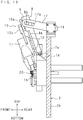
- FIG. 3 is an enlarged right side view schematically showing a cutting device support wall 7 and a cutting device 8.
- the alternate long and short dash line of FIG. 3 represents an extension line from the front surface of the cutting device support wall 7.
- the cutting device support wall 7 is provided between the first support portion 1 and the second support portion 2.
- the cutting device support wall 7 extends in the top-bottom direction.
- the cutting device 8 is supported on the upper part of the front surface of the cutting device support wall 7.
- the cutting device 8 is provided with a rail mount 9, a crank mechanism 10, a slider 11 and a blade 13.
- the rail mount 9 extends in the top-bottom direction. As shown in FIG. 1 and FIG.
- the rail mount 9 is inclined so as to protrude forwardly as a position of the rail mount 9 is located upwardly with respect to the front surface of the cutting device support wall 7.
- the posture of the rail mount 9 is a forward leaning posture.
- the angle ⁇ formed between the rear surface of the rail mount 9 and the front surface of the cutting device support wall 7 is set to not more than 30 degrees, for example, 20 degrees.
- a rail 9a is provided that extends in the top-bottom direction in the inclination direction of the rail mount 9.
- the slider 11 is slidably provided through sliding elements 12.
- the crank mechanism 10 is provided on the upper end portion of the rail mount 9.
- the crank mechanism 10 is provided with: a motor 10d attached to the upper end portion of the rail mount 9; a rotating disk 10a with a rotation axis extending in the front-rear direction; and a coupling plate 10c. To the center of the rotating disk 10a, a rotation shaft of the motor 10d is coaxially coupled.
- the coupling plate 10c extends in the top-bottom direction, and the upper end portion of the coupling plate 10c and the rotating disk 10a are coupled together through a pivot 10b.
- the pivot 10b is disposed in a position away from the rotation center of the rotating disk 10a.
- the lower end portion of the coupling plate 10c and the slider 11 are coupled together through a pivot (not shown).
- To the lower end portion of the slider 11, the blade 13 that cuts the wire 20 is attached.
- the rotation of the motor 10d is converted to a movement in the top-bottom direction by the crank mechanism 10, and the slider 11 and the blade 13 make a linear movement in the top-bottom direction in the inclination direction of the rail mount 9.
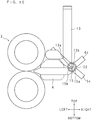
- FIG. 4 is an enlarged front view schematically showing the wire sending rollers 3, the blade 13, a coiling mandrel 15 and the like
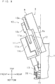
- FIG. 5 is an enlarged right side cross-sectional view schematically showing the cutting device 8 and the coiling mandrel 15.
- the alternate long and short dash line represents an axial center 15d of a semicircular column portion 15a
- the alternate long and two short dashes line represents a vertical line N orthogonal to the axial center 15d.
- the coiling mandrel 15 is provided on the lower side of the cutting device 8.
- the coiling mandrel 15 is columnar, and protrudes forward from the front surface of the cutting device support wall 7.
- the front shape of the semicircular column portion 15a is a semicircular shape having an arc swelling so as to protrude rightward and a chord coupling the upper end and the lower end of the arc.
- the semicircular shape is not limited to a shape where the ratio between the length of the chord (longitudinal length) and the length in the direction orthogonal to the chord (lateral length) is 2:1 but includes a shape where the ratio is 2:1.3 or the like.
- the left side surface (surface corresponding to the chord) of the semicircular column portion 15a forms a sliding surface 15b where the blade 13 slides.
- the part of the coiling mandrel 15 behind the semicircular column portion 15a (hereinafter, referred to as the rear part of the coiling mandrel 15) has a rectangular parallelepiped shape.
- the left side surface of the semicircular column portion 15a and the left side surface of the rear part of the coiling mandrel 15 are substantially flush with each other.
- the cross-sectional area of the rear part of the coiling mandrel 15 on the cross section orthogonal to the axis is larger than the cross-sectional area of the semicircular column portion 15a.
- the blade 13 has a rectangular parallelepiped shape, and extends in the top-bottom direction in the inclination direction of the rail mount 9. That is, like the posture of the rail mount 9, the posture of the blade 13 is a forward leaning posture. As shown in FIG. 4 , on the bottom surface of the blade 13, an inclined surface 13a is formed that is inclined so as to descend toward the right. As shown by the arrow of FIG. 5 , the blade 13 moves up obliquely forward and moves down obliquely rearward. In other words, in side view, the blade 13 of the cutting device 8 is movable in a direction inclined with respect to the axial center 15d.
- the angle of inclination of the blade 13 with respect to the vertical line N orthogonal to the axial center 15d is substantially the same as the above-mentioned angle ⁇ .
- the cutting device 8 is positioned so that the right side surface of the blade 13 and the sliding surface 15b of the semicircular column portion 15a are substantially flush with each other.
- the wire 20 sent out rightward by the wire sending rollers 3 abuts on the grooves of the bending dies 5c and 6c, and is bent so as to surround the peripheral surface of the semicircular column portion 15a.
- the wire 20 having been bent is in coil form, and is grown toward the front.
- the slider 11 moves down, and the upper side of the rear end portion of the wire 20 formed in coil form is sandwiched between the end of the inclined surface 13a of the blade 13 and an upper edge 15c of the sliding surface 15b (hereinafter, the wire 20 formed in coil form will be referred to also as coil or coil spring).
- the slider 11 further moves down and cuts the wire 20. Thereafter, the slider 11 moves up.
- the blade 13 cuts only the rear end portion of the coil.
- the axial center 15d is substantially parallel to the axial center of the coil and the axial center of the entire coiling mandrel 15.
- the cutting device support wall 7 may be formed of one member or may be formed of a plurality of members.
- the cutting device support wall 7 may be provided with a member supporting the coiling mandrel 15 and a member supporting the cutting device 8.
- the cutting device 8 and the coiling mandrel 15 are formed so as to be movable in the top-bottom direction. The manufacturer changes the positions, in the top-bottom direction, of the cutting device 8 and the coiling mandrel 15 according to the diameter of the spring to be manufactured.
- the wire 20 is cut by the coiling mandrel 15 fixed to the cutting device support wall 7 and the blade 13 attached to the slider 11.
- the coiling mandrel 15 with dimensions corresponding to the inside diameter is used. For this reason, even when a spring with a small inside diameter is manufactured, the part to be cut of the wire 20, for example, the upper end portion of the wound wire 20 can be cut.
- the dimensions of the coiling mandrel 15 correspond to a spring with a small inside diameter, for example, a spring where a so-called spring index is not more than 4, the cross-sectional area of the end portion (the semicircular column portion 15a) of the coiling mandrel 15 taken along a surface orthogonal to the axial center 15d is small, so that if the load acting on the coiling mandrel 15 at the time of cutting concentrates in the radial direction, the coiling mandrel 15 readily breaks. For this reason, conventionally, it is necessary to design the coiling mandrel 15 so that the cross-sectional area of the semicircular column portion 15a is small while the strength is maintained.
- the load acting on the coiling mandrel 15 from the cutting device 8 at the time of cutting of the wire 20 acts not only in the radial direction of the coiling mandrel 15 but also in the axial direction thereof. That is, the load acting on the coiling mandrel 15 is dispersed in the radial direction and in the axial direction.
- the angle ⁇ exceeds 30 degrees, there is a possibility that not only the rear end portion of the coil but also the center side portion of the coil is cut.
- the angle ⁇ of inclination of the cutting device 8 with respect to the cutting device support wall 7 it is made easy to cut only the rear end portion of the coil.
- the distance between the upper end portion of the cutting device 8 and the cutting device support wall 7 is prevented from becoming excessive, and the overall rigidness of the spring manufacturing machine is prevented from decreasing.
- the median diameter (the median value between the inside diameter and the outside diameter) of the coil spring is D and the diameter of the wire 20 is d.
- D/d is a spring index. It is typical to select the wire 20 so that the spring index D/d>4 when the slider 11 is moved in the vertical direction. This is because when D/d ⁇ 4, the shearing force acting on the coiling mandrel 15 from the cutting device 8 (a force acting in the radial direction of the coiling mandrel 15 or a force acting in a direction orthogonal to the axial center 15d) is excessive and this increases the possibility that the coiling mandrel 15 breaks.
- the load acting on the coiling mandrel 15 is dispersed in the radial direction and in the axial direction, so that even when the spring index D/d ⁇ 4, the shearing force acting on the coiling mandrel 15 from the cutting device 8 does not readily become excessive.
- the material of the coiling mandrel 15 for example, a super hard alloy or a high-speed steel is used.
- the super hard alloy since the hardness of the coiling mandrel 15 is very high, for example, even if an oil-tempered wire which is a heat-treated material comparatively high in hardness is used for the wire 20, the wire 20 can be cut with burr generation being suppressed.
- the super hard alloy has a characteristic of being fragile, and when the slider 11 is moved in the vertical direction, the shearing force acting on the coiling mandrel 15 from the blade 13 is excessive, so that there is a possibility that the coiling mandrel 15 breaks.
- the load acting on the coiling mandrel 15 is dispersed in the radial direction and in the axial direction by making the posture of the cutting device 8 oblique, even when the spring index is lower than a predetermined value, specifically, when D/d ⁇ 4, by selecting the super hard alloy as the material of the coiling mandrel 15, it is possible to cut the high hardness wire 20 with burr generation being suppressed and prevent the breakage of the coiling mandrel 15. By suppressing burr generation, high-quality coil springs can be continuously manufactured.
- the load acting on the coiling mandrel 15 is dispersed in the radial direction and in the axial direction. For this reason, even if burrs are generated, the burrs are readily directed in the axial direction, and the burrs are difficult to protrude inward in the radial direction of the coil, so that the degradation in the quality of the coil spring can be suppressed.
- the cutting device 8 may move down obliquely forward.
- a rearward force in the axial direction acts on the coiling mandrel 15.
- a forward force in the axial direction acts on the coiling mandrel 15.
- the rear portion of the coiling mandrel 15 is larger in cross-sectional area than the front portion (the semicircular column portion 15a) and is higher in rigidness than the front portion.
- the action of the rearward force in the axial direction is preferable in view of strength to the action of the forward force in the axial direction, and it is preferable because the coiling mandrel 15 is difficult to move forward in the axial direction.
- the coiling mandrel 15 moves forward, there is a possibility that the cut spring is caught on the coiling mandrel 15 and remains on the coiling mandrel 15.
- the conventional spring manufacturing machine described in Japanese Patent No. 6,403,224 is provided with an inclined cutting tool support wall and two cutting tools supported by the cutting tool support wall.
- the two cutting tools are brought close to each other to cut the upper end portion of the wire.
- One cutting tool is inserted into the inside of the coil through a gap in the neighborhood of the rear end portion of the wound wire (coil), the other cutting tool approaches the coil from the outside, the wire is sandwiched between the two cutting tools, and the upper end portion of the coil is cut.
- the inside diameter of the coil is small, the gap is also small, the one cutting tool cannot be inserted into the inside of the coil, and the one cutting tool interferes with the lower part of the coil, so that there is a possibility that the spring cannot be precisely manufactured.
- the spring manufacturing machine is capable of precisely manufacturing the spring without the blade 13 interfering with a part of the coil other than the part to be cut, for example, the lower end portion of the coil.
- FIG. 6 is a schematic front view of the spring manufacturing machine
- FIG. 7 is a vertical cross section taken along the line VII-VII shown in FIG. 6 .
- a support mount 14 is fixed to the front surface of the cutting device support wall 7.
- the support mount 14 and the lower end portion of the rail mount 9 are coupled together through a pivot 7a with the right-left direction as the axial direction.
- the rail mount 9 is rotatable around the pivot 7a. That is, the cutting device 8 is capable of changing the angle of inclination with respect to the cutting device support wall 7.
- a motor 16 is attached to the upper portion 2d of the second support portion 2.
- the rotation shaft of the motor 16 and the rail mount 9 are coupled together through a rotating plate 17.
- the rotating plate 17 is oval, and to one end portion thereof, the rotation shaft of the motor 16 is orthogonally coupled.
- the guide hole 17a passes through the rotating plate 17 and is in the form of an oblong hole elongated in the length direction of the rotating plate 17.
- the rail mount 9 is provided with a protruding portion 9b protruding rightward, and the protruding portion 9b is inserted into the guide hole 17a.
- the rotating plate 17 is rotated by the rotation of the motor 16.
- the protruding portion 9b is guided by the guide hole 17a, the position of the protruding portion 9b is changed, and the angle of inclination of the cutting device 8 with respect to the cutting device support wall 7 is changed. That is, the posture of the cutting device 8 is adjusted.
- the inclination angle of the cutting device 8 can be adjusted until the posture becomes a desired one.
- the wire 20 can be cut at an appropriate angle corresponding to the kind of the wire 20 and the spring index by adjusting the posture of the cutting device 8.
- FIG. 8 is a perspective view schematically showing a spring manufacturing machine according to a modification.
- the spring manufacturing machine according to the modification uses an adjustment plate 21 instead of the rotating plate 17.
- the upper portion 1d of the first support portion 1 and the rail mount 9 are coupled together through the adjustment plate 21.
- the adjustment plate 21 is oval, and a guide hole 21a is formed on one end portion thereof.
- the guide hole 21a passes through the adjustment plate 2 and is in the form of an oblong hole elongated in the length direction of the adjustment plate 21.
- a protruding portion 7b protruding rightward is formed on the upper end portion of the cutting device support wall 7, a protruding portion 7b protruding rightward is formed.
- the protruding portion 7b is inserted in the guide hole 21a of the adjustment plate 21.
- the other end portion of the adjustment plate 21 is connected to the rail mount 9 through a pivot 9c with the right-left direction as the axial direction.
- the user can position the cutting device 8 at an appropriate angle by rotating the rail mount 9 around the pivot 7a (see FIG. 7 ) to fix the protruding portion 7b by the guide hole 21a.
- the positioning of the cutting device 8 may be automatically performed by using a motor or may be manually performed.
- FIG. 9 is an enlarged right side view schematically showing the cutting device support wall 7 and the cutting device 8.
- the slider 11 is provided with a rear portion 11a and a front portion 11b.
- the rear portion 11a extends in the top-bottom direction along the rail mount 9.
- the upper end portion of the rear portion 11a and the rotating disk 10a are coupled together through the coupling plate 10c.
- the rear portion 11a is slidably provided on the rail 9a through the sliding elements 12.
- the front portion 11b is provided on the front side of the rear portion 11a.
- the front portion 11b and the rear portion 11a are coupled together by a pivot 11c.
- the axial direction of the pivot 11c is a direction orthogonal to the inclination direction of the rail mount 9.
- To the lower end portion of the front portion 11b the blade 13 is attached.
- FIG. 10 is an enlarged front view schematically showing the wire sending rollers 3, the blade 13, the coiling mandrel 15 and the like
- FIG. 11 is an enlarged right side cross-sectional view schematically showing the cutting device 8 and the coiling mandrel 15.
- the inclined surface 13a inclined so as to descend toward the right and a parallel surface 13b continuous with the right end of the inclined surface 13a and parallel to the axial center 15d of the semicircular column portion 15a are formed.
- the parallel surface 13b is formed only on the right front end portion of the bottom surface of the blade 13.
- FIG. 12 is an enlarged front explanatory view explaining a movement locus of the blade 13.
- the solid arrow shows the movement locus of the blade 13.
- the rear portion 11a of the slider 11 linearly moves in the top-bottom direction along the rail 9a by the driving of the crank mechanism 10. Since the front portion 11b of the slider 11 is coupled to the rear portion 11a through the pivot 11c, it swings in the right-left direction with respect to the rear portion 11a. For this reason, the blade 13 moves in the top-bottom direction and in the right-left direction, and as shown by the solid line of FIG. 12 , the movement locus of the blade 13 (more specifically, the movement locus of the parallel surface 13b) is an oval elongated in the top-bottom direction.
- the position of the cutting device 8 is set so that the lower end portion of this oval is situated at the upper end portion of the wire 20 formed in coil form.
- the wire 20 sent out rightward by the wire sending rollers 3 abuts on the grooves of the bending dies 5c and 6c, and is bent so as to surround the peripheral surface of the semicircular column portion 15a.
- the wire 20 having been bent is in coil form, and is grown toward the front.
- the blade 13 moves down along the oval locus, and the upper side of the rear end portion of the wire 20 formed in coil form is sandwiched between the parallel surface 13b of the blade 13 and the upper edge 15c of the sliding surface 15b.
- the blade 13 cuts the wire 20 and moves up.
- the parallel surface 13b cuts only the rear end portion of the coil.
- the broken line arrow of FIG. 12 shows the movement locus of the blade 13 when a blade 13 similar to the blade 13 of the first embodiment, that is, a blade 13 where the parallel surface 13b is not formed is used.
- the movement locus is an oval elongated in the top-bottom direction. The lower end portion of this oval is situated below the upper end of the coiling mandrel 15. That is, it interferes with the coiling mandrel 15.
- the position of the blade 13 is moved upward in order to prevent the interference with the coiling mandrel 15, there is a possibility that cutting of the coil is insufficient and the coil cannot be cut.
- the spring manufacturing machine by forming the parallel portion on the blade 13 of the slider 11, when the blade 13 is moved along a circular locus, for example, along an oval locus to cut the wire 20, the blade 13 is prevented from interfering with the coiling mandrel 15 and the wire 20 can be surely cut. Moreover, compared with when the blade 13 is linearly moved, burr generation is difficult to occur on the coil, so that the degradation in the quality of the coil spring can be suppressed.
- FIG. 13 is an enlarged right side explanatory view explaining a movement locus of the blade 13.
- the arrow of FIG. 13 shows the movement locus of the blade 13.
- a structure may be adopted in which the slider 11 is formed of two parts of a right portion and a left portion, these are coupled together by a pivot with the right-left direction as the axial direction, one is attached to the rail 9a and the other is attached to the blade 13.
- the blade 13 can be swung in the front-rear direction without the motor 16 being driven.
- the above-described spring manufacturing machine in which the cutting device 8 is disposed above the coiling mandrel 15 manufactures a right-hand coil.
- the cutting device 8 is disposed below the coiling mandrel 15.
- the spring manufacturing machine is capable of manufacturing not only the coil spring but also other kinds of springs.
- a ring spring can be manufactured.
- the shape of the end portion of the coiling mandrel does not have to be a semicircle and may be, for example, a rectangular parallelepiped.
- the angle of inclination of the cutting device 8 with respect to the cutting device support wall 7 does not have to be not more than 30 degrees and may be, for example, an arbitrary angle in a range of 30 degrees to 90 degrees.
- the movement locus of the blade 13 does not have to be a circle or an oval and may be, for example, a line.
Landscapes
- Engineering & Computer Science (AREA)
- Mechanical Engineering (AREA)
- Wire Processing (AREA)
Applications Claiming Priority (1)
| Application Number | Priority Date | Filing Date | Title |
|---|---|---|---|
| JP2019000635A JP6661035B1 (ja) | 2019-01-07 | 2019-01-07 | ばね製造機 |
Publications (1)
| Publication Number | Publication Date |
|---|---|
| EP3677360A1 true EP3677360A1 (de) | 2020-07-08 |
Family
ID=68699181
Family Applications (1)
| Application Number | Title | Priority Date | Filing Date |
|---|---|---|---|
| EP19211560.8A Withdrawn EP3677360A1 (de) | 2019-01-07 | 2019-11-26 | Federherstellungsmaschine |
Country Status (3)
| Country | Link |
|---|---|
| US (1) | US20200215598A1 (de) |
| EP (1) | EP3677360A1 (de) |
| JP (1) | JP6661035B1 (de) |
Families Citing this family (1)
| Publication number | Priority date | Publication date | Assignee | Title |
|---|---|---|---|---|
| JP6979230B2 (ja) * | 2020-05-08 | 2021-12-08 | 新興機械工業株式会社 | 切断装置、受け部及びホルダ |
Citations (5)
| Publication number | Priority date | Publication date | Assignee | Title |
|---|---|---|---|---|
| FR1478184A (fr) * | 1966-05-03 | 1967-04-21 | Torrington Mfg Co | Machine à enrouler du fil métallique pour fabriquer des ressorts |
| JPH1071442A (ja) * | 1996-03-25 | 1998-03-17 | Wafios Mas Fab Gmbh | 切断装置を有する線材を成形する装置 |
| EP0950445A2 (de) * | 1998-04-17 | 1999-10-20 | Bobbio S.R.L. | Verfahren und Vorrichtung zur Herstellung von Schraubenfedern |
| JP2016175111A (ja) * | 2015-03-20 | 2016-10-06 | 旭精機工業株式会社 | ばね成形機 |
| JP2017177161A (ja) * | 2016-03-30 | 2017-10-05 | 旭精機工業株式会社 | ばね成形機 |
-
2019
- 2019-01-07 JP JP2019000635A patent/JP6661035B1/ja not_active Expired - Fee Related
- 2019-11-15 US US16/685,189 patent/US20200215598A1/en not_active Abandoned
- 2019-11-26 EP EP19211560.8A patent/EP3677360A1/de not_active Withdrawn
Patent Citations (6)
| Publication number | Priority date | Publication date | Assignee | Title |
|---|---|---|---|---|
| FR1478184A (fr) * | 1966-05-03 | 1967-04-21 | Torrington Mfg Co | Machine à enrouler du fil métallique pour fabriquer des ressorts |
| JPH1071442A (ja) * | 1996-03-25 | 1998-03-17 | Wafios Mas Fab Gmbh | 切断装置を有する線材を成形する装置 |
| EP0950445A2 (de) * | 1998-04-17 | 1999-10-20 | Bobbio S.R.L. | Verfahren und Vorrichtung zur Herstellung von Schraubenfedern |
| JP2016175111A (ja) * | 2015-03-20 | 2016-10-06 | 旭精機工業株式会社 | ばね成形機 |
| JP2017177161A (ja) * | 2016-03-30 | 2017-10-05 | 旭精機工業株式会社 | ばね成形機 |
| JP6403224B2 (ja) | 2016-03-30 | 2018-10-10 | 旭精機工業株式会社 | ばね成形機 |
Also Published As
| Publication number | Publication date |
|---|---|
| JP6661035B1 (ja) | 2020-03-11 |
| JP2020108901A (ja) | 2020-07-16 |
| US20200215598A1 (en) | 2020-07-09 |
Similar Documents
| Publication | Publication Date | Title |
|---|---|---|
| EP3903958A1 (de) | Wickelmaschine, verfahren zur herstellung einer schraubenfeder und schraubenfeder | |
| JP2675523B2 (ja) | バネ製造装置 | |
| US9366286B2 (en) | Radial foil bearing | |
| JP5249517B2 (ja) | ホールソー | |
| US5732583A (en) | Wire forming apparatus | |
| EP2535129A1 (de) | Bohrmeißel | |
| US20180250756A1 (en) | Drill and method for manufacturing cut product using same | |
| US20080264132A1 (en) | Spring manufacturing machine | |
| EP3677360A1 (de) | Federherstellungsmaschine | |
| EP3587707B1 (de) | Bindemaschine | |
| JPWO2008111215A1 (ja) | ダイヤモンドダイスおよびそれを用いた線材の製造方法 | |
| EP3162518B1 (de) | Elektrischer rotationsrasierapparat | |
| JP2009025654A (ja) | 回折光学素子、回折光学素子成形用金型、および回折光学素子成形用金型の製造方法 | |
| CN103429402B (zh) | 片材切割用旋转刀具及其制造方法、以及使用了该片材切割用旋转刀具的旋转切割器 | |
| JP3842239B2 (ja) | 内曲げフックを有するコイルばねの成形方法およびその装置 | |
| KR102429072B1 (ko) | 디버링툴 조립체 | |
| JP6403224B2 (ja) | ばね成形機 | |
| JP2887559B2 (ja) | コイリングマシンの線材切断装置 | |
| EP1371809A1 (de) | "jalousie, lamelle für jalousien und verfahren zur herstellung derselben und herstellungsmaschine dafür" | |
| JP5010174B2 (ja) | 回転電機用鉄心片の製造装置 | |
| JP2010052111A (ja) | ワイヤカッター | |
| US7426846B2 (en) | Automatic bending machine for manufacturing of steel rule cutting dies | |
| JP5412097B2 (ja) | チップドレッサ | |
| JP5173217B2 (ja) | 薄板打抜き加工方法及び打抜き加工装置 | |
| US20230405664A1 (en) | Rebar tying tool |
Legal Events
| Date | Code | Title | Description |
|---|---|---|---|
| PUAI | Public reference made under article 153(3) epc to a published international application that has entered the european phase |
Free format text: ORIGINAL CODE: 0009012 |
|
| STAA | Information on the status of an ep patent application or granted ep patent |
Free format text: STATUS: THE APPLICATION HAS BEEN PUBLISHED |
|
| AK | Designated contracting states |
Kind code of ref document: A1 Designated state(s): AL AT BE BG CH CY CZ DE DK EE ES FI FR GB GR HR HU IE IS IT LI LT LU LV MC MK MT NL NO PL PT RO RS SE SI SK SM TR |
|
| AX | Request for extension of the european patent |
Extension state: BA ME |
|
| STAA | Information on the status of an ep patent application or granted ep patent |
Free format text: STATUS: THE APPLICATION IS DEEMED TO BE WITHDRAWN |
|
| 18D | Application deemed to be withdrawn |
Effective date: 20210112 |