EP3677484B1 - Verbindungsvorrichtung zwischen dem zuganker und den plattformen am ende eines transportwaggons für den kombinierten schienen-strassen-verkehr - Google Patents
Verbindungsvorrichtung zwischen dem zuganker und den plattformen am ende eines transportwaggons für den kombinierten schienen-strassen-verkehr Download PDFInfo
- Publication number
- EP3677484B1 EP3677484B1 EP19205800.6A EP19205800A EP3677484B1 EP 3677484 B1 EP3677484 B1 EP 3677484B1 EP 19205800 A EP19205800 A EP 19205800A EP 3677484 B1 EP3677484 B1 EP 3677484B1
- Authority
- EP
- European Patent Office
- Prior art keywords
- pull ring
- nut
- rod
- connecting device
- rail wagon
- Prior art date
- Legal status (The legal status is an assumption and is not a legal conclusion. Google has not performed a legal analysis and makes no representation as to the accuracy of the status listed.)
- Active
Links
Images


Classifications
-
- B—PERFORMING OPERATIONS; TRANSPORTING
- B61—RAILWAYS
- B61D—BODY DETAILS OR KINDS OF RAILWAY VEHICLES
- B61D3/00—Wagons or vans
- B61D3/16—Wagons or vans adapted for carrying special loads
- B61D3/18—Wagons or vans adapted for carrying special loads for vehicles
- B61D3/187—Details, e.g. bridges for floor connections
-
- B—PERFORMING OPERATIONS; TRANSPORTING
- B61—RAILWAYS
- B61D—BODY DETAILS OR KINDS OF RAILWAY VEHICLES
- B61D3/00—Wagons or vans
- B61D3/16—Wagons or vans adapted for carrying special loads
- B61D3/18—Wagons or vans adapted for carrying special loads for vehicles
- B61D3/182—Wagons or vans adapted for carrying special loads for vehicles specially adapted for heavy vehicles, e.g. public work vehicles, trucks, trailers
- B61D3/184—Wagons or vans adapted for carrying special loads for vehicles specially adapted for heavy vehicles, e.g. public work vehicles, trucks, trailers the heavy vehicles being of the trailer or semi-trailer type
-
- B—PERFORMING OPERATIONS; TRANSPORTING
- B61—RAILWAYS
- B61D—BODY DETAILS OR KINDS OF RAILWAY VEHICLES
- B61D47/00—Loading or unloading devices combined with vehicles, e.g. loading platforms, doors convertible into loading and unloading ramps
- B61D47/005—Loading or unloading devices combined with road vehicles carrying wagons, e.g. ramps, turntables, lifting means
Definitions
- the present invention relates to a railway wagon for the combined rail / road transport of a road load and comprising two end platforms equipped with bogies, interconnected by a tie rod, and supporting a pivoting structure carrying the road load.
- the invention relates more particularly to a connecting device designed to connect each end platform to the tie rod.
- a railway wagon for the combined rail / road transport of a road load which comprises two end platforms equipped with bogies, interconnected by a tie rod, and supporting a pivoting structure carrying the road load.
- the pivoting structure can pivot horizontally with respect to the end platforms between a transport position along the longitudinal axis of the wagon and an oblique or perpendicular loading / unloading position in which the road load can freely circulate between the loading dock and the bearing surface of the swivel structure.
- Such a wagon is for example known from the document EP 1292478 .
- the pivoting structure also generally as a supporting structure, is pivotally mounted around a pivot provided on a tie rod which connects the two end platforms.
- the tie rod is generally equipped with bellows in order to allow the tie rod to descend relative to the pivoting structure in order to disengage the latter from the tie rod and allow it to pivot.
- the tie-rod is in the form of a longitudinal connecting element which is fixed or articulated by each of its ends to an end platform in the lower part thereof.
- the tie rod has no other main purpose than to mechanically connect the two end platforms to each other in order to retain them in their initial position during the loading / unloading phases. It is generally made with a small thickness so as not to penalize the useful loading dimensions with respect to the rail gauge. Indeed, the tie rod is only subject to its own weight and possible forces of separation and approach of the end platforms.
- the pivoting structure When the wagon is in the transport position, or "closed wagon” position, the pivoting structure is in the low position and aligned longitudinally with the two end platforms, while when the wagon is in the loading / unloading position, or "open wagon position” »
- the swivel structure is in a high position and oblique or perpendicular to the two end platforms.
- the tie rod when the wagon is in the transport position, or in the "closed wagon” position, the tie rod does not take up the torque generated by the pocket and is only used to support conduits and cables, while when the wagon is in an oblique position or perpendicular for loading / unloading, or in the "open wagon” position, the tie rod keeps the two end platforms in position and materializes the pivoting center of the pivoting structure.
- the tie rod also allows the mounting and circulation of the pneumatic pipes and the electric cables of the wagon.
- tie rod is in the form of a middle part extending along the longitudinal axis of the wagon and comprising a fork with two arms provided at each end of the middle part.
- the tie rod is simply fixed or articulated to an end platform by each of the free ends of the arms of the forks. To correct the aforementioned defects, it is therefore necessary to twist and force the tie rod until its deformations have no effect, and nothing is provided to allow the tie rod in particular to take up the torque generated by the pivoting structure resulting in a tensile force in the tie rod. To correct these defects, in the document EP 1292478 it is usually necessary to apply strong forces in order to deform the tie rod arms, usually empirically, until the wagon frame is flat and the stresses to each of the tie rod arms are substantially the same.
- the object of the present invention therefore aims to overcome the drawbacks of the prior art by proposing a new connecting device designed to connect each end platform to the arms of the tie rod in a rail car of the type as described above.
- each connecting device By screwing or unscrewing the nut on the threaded end of the rod of the traction ring within each connecting device, it is advantageously possible to adjust the distance between each of the arms of the forks of the tie rod and the end platform on which they are fixed.
- the tie rod it is simple and easy to shape the tie rod so that it guarantees a planar geometry of the frame and makes it possible to have an isostatic connection with the two end platforms.
- the nut of each connecting device has an annular groove provided in the face of the nut located on the side of the receiving part.
- This annular groove makes it possible to reduce the stiffness of the nut and thus to reduce the mechanical stresses in the first engaged threads. It advantageously makes it possible to considerably increase the service life of the nut which retains the arms and whose thread is subjected to all tensile forces.
- the locknut advantageously makes it possible to limit the movement of the tie rod relative to the end platforms in the event of a compressive force, in particular during the loading / unloading phases.
- each connecting device further comprises a device for immobilizing and securing the nut which prevents rotation of the nut.
- the rod of the traction ring comprises at least one longitudinal groove and the device for immobilizing and securing the nut comprises a nut stop plate fixed on the nut and having a central hole comprising at least one immobilizing tab projecting towards the center of said central hole, said nut stop plate being mounted on the rod of the pull ring with the at least one immobilization tab housed in at least one longitudinal groove of said rod.
- This device advantageously makes it possible to prevent the rotation of the traction ring around its longitudinal axis in which the rod is located.
- the nut stop plate is fixed to the nut by at least one screw locked in rotation.
- the device for preventing rotation of the pull ring is itself secure.
- each connecting device further comprises a lock nut stop piece having a fixing end fixed to the lock nut and a retaining end opposite to the fixing end. and extending towards the tie rod, this retaining end penetrating at least partially between the two horizontal and parallel plates of the traction ring and advantageously preventing the rotation of the locknut relative to the traction ring.
- This stop piece also advantageously makes it possible to protect the thread of the traction ring.
- each connecting device further comprises a support ring mounted on the rod of the traction ring between the receiving part and the nut, this nut being a nut within reach spherical, the convex portion of which with a spherical seat is directed towards the support ring, the contact surface of the support ring being concave and with a spherical seat.
- each connecting device further comprises a washer mounted on the rod of the traction ring between the receiving part and the locknut. This washer advantageously allows the locknut to be tightened against the receiving part of the end platform.
- the washer is a spring washer.
- This spring washer is preferably tightened by the lock nut, but is not flattened in order to advantageously keep the ball joint of the nut.
- the horizontal plate of the distal free end of the arms of the forks and / or each horizontal plate of the first part of the traction ring is / are of substantially oval shape.
- the conformation of the horizontal plates also makes it possible to form a reliable and robust articulation between each traction ring and the arm of the tie rod to which it is connected.
- the receiving part is in the form of a fixing loop provided orthogonal to the surface of the end platform on which it is secured or shaped.
- the receiving part comprises a tubular sheath housed in its through orifice and intended to come into contact with the rod of the traction ring.
- This sheath makes it possible in particular to avoid any wear between the rod of the traction ring and the receiving part of the end platform in which it is received.
- each connecting device further comprises an additional connecting device retaining the distal free end of the fork arm with the end platform in the event of failure of the means retaining the stem. the traction ring with said end platform.
- This additional redundant connection device provides additional security and advantageously makes it possible to prevent a pulling ring from becoming detached from the end platform to which it is connected.
- the additional connection device is inexpensive, robust, efficient and simple to implement. Thanks to the oblong, it allows freedom of movement of each tie rod relative to the platform, which advantageously allows the adjustment made by the nut, while retaining the traction ring to the end platform in the event of failure in particular of the nut.
- each connecting device further comprises a housing shaped in each end platform, into which at least partially penetrates the rod of the traction ring and the fixing part, the vertical support axis and the through-hole of the receiving part being housed in this housing.
- each connection device further comprises an additional safety device provided on the end platform and comprising a safety strip located under the traction ring, in the immediate vicinity of said traction ring.
- This additional redundant safety device provides additional safety and advantageously makes it possible to support the traction ring from below in order to prevent in particular that in the event of an impact or significant weight undergone by the traction ring, the latter is not damaged or does not separate from the end platform to which it is connected.
- the connecting device of the invention in addition to making it possible to adjust the distance between each of the arms of the forks of the tie-rod and the end platform on which they are fixed, has numerous devices aimed at securing its constituent means and at redundant its liaison function in the event of failure. It thus offers maximum security for connecting the tie rod to the end platforms.
- the railway wagon (1) according to the invention is intended for combined rail / road transport and the loading / unloading of a road load, preferably a semi-trailer. Such a railway wagon (1) is shown in a simplified manner on the figure 1 .
- the railway wagon (1) according to the invention comprises two end platforms (2) connected by a tie rod (3) and equipped with bogies (4). It is this assembly (2, 3) which allows the railway wagon (1) according to the invention to run on rails.
- the tie rod (3) is connected to each end platform (2) by a connecting device (not shown). Each of these connecting devices is preferably located at the level of the tie rod (3), in the lower part of each of the end platforms (2).
- a tie rod (3) according to the invention is shown by way of example on the figure 2 .
- This assembly (2, 3) formed by the end platforms (2) and the tie rod (3) support a pivoting structure (5) carrying the road load.
- the tie-rod (3) is equipped with a pivot (6) which allows the pivoting structure (5) to be animated with a pivoting movement back and forth, in a horizontal plane, towards and beyond a platform between a transport position along the longitudinal axis of the railway wagon (1) and a loading / unloading position oblique or perpendicular to the transport position.
- the ends of the pivoting structure (5) are open and accessible from the dock to allow the user to load or unload a road load on or outside said pivoting structure (5).
- the pivoting structure (5) and the two end platforms (2) are mutually associated and aligned along the longitudinal axis of the railway wagon (1) and the ends of the pivoting structure (5) are closed by the end platforms (2).
- pivoting structure (5) When the pivoting structure (5) is in the transport position, a lifting mechanism outside the wagon makes it possible to move the pivoting structure (5) vertically with respect to the two end platforms (2), so that said pivoting structure (5) ) is dissociated from the two end platforms (2) and can freely pivot relative to them.
- the pivoting structure (5) can thus adopt a high position and a low position.
- a mechanism generally in the form of a bellows provided at the level of the pivot (6) of the tie rod (3), allows the tie rod (3) to be released vertically from the pivoting structure (5) during the opening phases.
- the pivoting structure (5) comprises a horizontal loading platform (7) bordered longitudinally by two protective side walls (8) delimited upwards by upper longitudinal members (9). These upper side members (9) usually make it possible to stiffen and support the pivoting structure (5).
- the swivel structure (5) is only shown on the figures 1 and 6 .
- the railway wagon (1) also comprises two connecting systems (10) provided to dissociably assemble the pivoting structure (5) and the two end platforms (2) when the pivoting structure (5) is in position. transport position.
- Each connection system (10) is thus provided between each of the end platforms (2) and the pivoting structure (5), at the ends facing these elements (2, 5).
- each connection system (10) can for example comprise male hooks (10a) provided at the ends of the upper side members (9) and female receiving hooks (10b) or projecting receiving parts provided at the inner ends of the two end platforms (2), the male hooks (10a) of the swivel structure (5) being provided for s 'engage in a dissociable manner with the female receiving hooks (10b) or the protruding receiving parts of the end platforms (2).
- the tie rod (3) according to the invention comprises a middle part (11) extending along the longitudinal axis of the railway wagon (1), as well as a fork (12) with two arms (13) provided at each end longitudinal sections of the middle part of the tie rod (3).
- the railway wagon (1) comprises four connecting devices (15) connecting the tie rod (3) to the two end platforms (2).
- the connecting systems (10) take up in the upper part the horizontal and longitudinal forces between the horizontal loading platform (7) and the two end platforms (2).
- the vertical support forces of the pivoting structure (5) on the two end platforms (2) are taken up by the tie rod (3).
- the tie rod (3) alone takes up the tilting forces of the end platforms (2), that is to say it prevents the end platforms (2) from pivoting about an axis transverse to the longitudinal axis of the railway wagon (1).
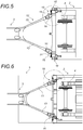
- each connecting device (15) comprises a traction ring (16) having a first part (17) directed towards the distal free end (14) of the fork arm (13) (12), the first part (17) of the traction ring (16) comprising two horizontal and parallel plates (18a, 18b), each having a through orifice (19), and between which is housed the distal free end (14) of said arm (13) of the forks (12).
- Each traction ring (16) also has a second part (20) secured or shaped as a single piece with the first part (17), said second part (20) being extended by a rod (21) whose free end (22) is threaded and is directed towards the end platform (2).
- a pull ring (16) is shown alone on the figure 12 .
- Each connecting device (15) also comprises an axis (23) housed vertically through a through hole (24) provided at the distal free end of the arm (13) of the forks (12) and through the through holes (19). of the pull ring (16) in order to assemble the pull ring (16) to said arm (13) of the forks (12) pivotally in a horizontal plane.
- Each connecting device (15) also comprises a receiving part (25) secured or shaped as a single piece with the end platform (2), and having a through orifice (26) through which the rod (21) is introduced. ) of the traction ring (16), so that the threaded part (22) of said rod (21) opens out on the other side of the through hole (26).
- Each connecting device (15) also comprises a nut (27) screwed onto the threaded end (22) of the rod (21) of the pulling ring (16) and a lock nut (28) screwed onto the rod (21) of the traction ring (16) between the receiving part (25) and the first part (17) of the traction ring (16).
- the nut (27) and the locknut (28) come to bear against the receiving part (25) and grip the latter in order to immobilize the rod (21) of the traction ring (16) in the part receiver (25).
- the thread of the rod (21) and that of the nut (27) is preferably a round thread which works better and tires less for non-prestressed screwing.
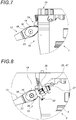
- each connecting device (15) further comprises a device for immobilizing and securing (29) the nut (27) which prevents rotation of the nut (27). .
- the rod (21) of the traction ring (16) can comprise at least one longitudinal groove (30), preferably two
- the device for immobilizing and securing (29) of the nut ( 27) comprises a nut stopper plate (31) fixed to the nut (27) and having a central hole (32) having at least one immobilizing tab (33) projecting towards the center of said central hole ( 32), said nut stop plate (31) being mounted on the rod (21) of the pull ring (16) with the at least one immobilizing tab (33) housed in the at least a longitudinal groove (30) of said rod (21), which prevents rotation of the nut (27).
- the nut stop plate (31) is preferably fixed to the nut (27) by at least one screw blocked in rotation, and more preferably by at least two screws (34, 35) blocked in rotation, c ' that is, each of these screws is equipped with a device that prevents its rotation.
- a screw can also be blocked in rotation by the use of a cam lock washer (38).
- the nut stop plate (31) is fixed to the nut (27) by at least two screws, including a first hexagonal head screw (34) locked in position. rotation by a plate plate (36) and a socket head cap screw (35), for example of the Allen or Torx type, associated with a cam lock washer (38).
- Each connecting device (15) preferably comprises a locknut stopper (39) having a fixing end (40) fixed to the locknut (28) and a retaining end (41) opposite to the fixing end (40) and extending towards the tie rod (3).
- the retaining end (41) penetrates at least partially between the two horizontal and parallel plates (18a, 18b) of the traction ring (16) in order in particular to prevent the rotation of the lock nut (28) with respect to the traction ring (16).
- Each connecting device (15) preferably comprises a support ring (42) mounted on the rod (21) of the traction ring (16) between the receiving part (25) and the nut (27), this nut (27) then preferably being a nut (27) with a spherical seat whose convex part with a spherical seat (43) is directed towards the support ring (42), the contact surface (44) of the support ring ( 42) being concave and spherical in contact.
- Each connecting device (15) preferably comprises a washer (45) mounted on the rod (21) of the traction ring (16) between the receiving part (25) and the lock nut (28). It is preferably a spring washer.
- the distal free end of the arm (13) of the forks (12) preferably comprises a horizontal plate (46) in which the through orifice (24) is formed.
- the horizontal plates (46) of the arms (13) of the tie rod (3) and the horizontal plates (18a, 18b) of the traction ring (16) are preferably of substantially oval shape.
- the receiving part (25) is in the form of a fixing loop (47) provided orthogonal to the surface of the end platform (2) on which it is secured or conformed.
- the receiving part (25) preferably comprises a tubular sheath (48) housed in its through orifice (26) and designed to come into contact with the rod (21) of the traction ring (16).
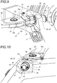
- each link device (15) further comprises a device additional connection (49) retaining the distal free end (14) of the fork arm (13) (12) with the end platform (2) in the event of failure of the means retaining the rod (21) of the ring traction (16) with said end platform (2).
- each additional connecting device (49) comprises a fastening part (50) secured or shaped as a single piece with the horizontal plate (46) of said fork (12) and extending in the direction of the end platform (2) along the longitudinal axis of the fork arm (13) (12).
- the fixing part (50) has a through oblong (51) through which penetrates a vertical support axis (52), secured to said end platform (2).
- the railway wagon (1) includes a redundancy solution based on a locking between the tie rod (3) and each end platform (2).
- each connecting device (15) further comprises a housing (53) shaped in each end platform (2), into which at least partially penetrates the rod (21) of the traction ring (16). and the fixing piece (50).
- the vertical support axis (52) and the through orifice (26) of the receiving part (25) are located in this housing (53).
- each connecting device (15) preferably comprises an additional safety device (54) provided on the end platform (2) and comprising a safety strip (55) located under the traction ring (16), to immediate proximity to said pull ring (16).
Landscapes
- Engineering & Computer Science (AREA)
- Transportation (AREA)
- Mechanical Engineering (AREA)
- Steering-Linkage Mechanisms And Four-Wheel Steering (AREA)
- Train Traffic Observation, Control, And Security (AREA)
- Connection Of Plates (AREA)
- Refuge Islands, Traffic Blockers, Or Guard Fence (AREA)
- Handcart (AREA)
Claims (16)
- Eisenbahnwaggon (1) für den kombinierten Transport Schiene/ Straße und das Be-/ Entladen einer Straßenladung, dieser Waggon enthält:• zwei Endplattformen (2), ausgerüstet mit Drehgestellen (4);• eine Stange (3), die die beiden Endplattformen (2) verbindet und ein Mittelteil (11) umfasst, das sich entlang der Längsachse des Eisenbahnwaggons (1) verlängert, sowie eine Gabel (12) mit zwei Armen (13), vorgesehen an jedem der Längsenden des Mittelteils (11) der Stange (3),• eine schwenkbare Struktur (5), beladen mit der Straßenladung, lösbar zusammengebaut mit den beiden Endplattformen (2) und oberhalb der Stange (3) zwischen den beiden Endplattformen (2) angeordnet;• eine Verbindungsvorrichtung (15) vorgesehen zwischen jedem freien distalen Endstück (14) der Arme (13) der Gabeln (12) und dem Endstück gegenüber jeder der Endplattformen (2):
dadurch gekennzeichnet, dass das freie distale Endstück (14) der Arme (13) der Gabeln (12) eine horizontale Platine (46) enthält, die eine durchführende Öffnung aufweist, jede Verbindungsvorrichtung (15) enthält dabei:• eine Zugöse (16), die enthält:- ein erstes Teil (17) ausgerichtet zum freien distalen Endstück (14) des Arms (13) der Gabel (12), das erste Teil (17) der Zugöse (16) enthält dabei zwei horizontale und parallele Platinen (18a, 18b), die jeweils eine durchführende Öffnung aufweisen und zwischen denen das freie distale Endstück dieses Arms (13) der Gabeln (12) untergebracht ist,- ein zweites Teil (20) fest verbunden mit oder in einem Stück mit dem ersten Teil (17) geformt, dieser zweite Teil (20) verlängert sich durch eine Stange (21) deren freies Endstück ein Gewinde aufweist und zur Endplattform (2) hin ausgerichtet ist;• eine Achse (23), montiert durch die durchführende Öffnung des freien distalen Endstücks des Arms (13) der Gabeln (12) hindurch sowie durch die durchführenden Öffnungen der Zugöse (16) um die Zugöse (16) mit diesem Arm (13) der Gabeln (12) zu verbinden;• ein Aufnahmeteil (25) fest verbunden mit oder in einem Stück mit der Endplattform (2) geformt, und das eine durchführende Öffnung aufweist, durch die die Stange (21) der Zugöse (16) hindurchgeführt wird;• eine Mutter (27), aufgeschraubt auf das Endstück mit Gewinde (22) der Stange (21) der Zugöse (16), die auf der anderen Seite der durchführenden Öffnung des Aufnahmeteils (25) mündet; und• eine Kontermutter (28) aufgeschraubt auf die Stange (21) der Zugöse (16) zwischen dem Aufnahmeteil (25) und dem ersten Teil (17) der Zugöse (16)• die Mutter (27) und die Kontermutter (28) werden gegen das Aufnahmeteil (25) gedrückt und spannen dieses ein, um die Stange (21) der Zugöse (16) im Aufnahmeteil (25) zu blockieren. - Eisenbahnwaggon (1) nach Anspruch 1, dadurch gekennzeichnet, dass die Mutter (27) jeder Verbindungsvorrichtung (15) eine ringförmige Kehle (56) aufweist, vorgesehen in der Seite der Mutter (27), die auf der Seite des Aufnahmeteils (25) angeordnet ist.
- Eisenbahnwaggon (1) nach Anspruch 1 oder 2, dadurch gekennzeichnet, dass jede Verbindungsvorrichtung (15) außerdem eine Vorrichtung zum Blockieren und Sichern (29) der Mutter (27) enthält, die eine Rotation der Mutter (27) verhindert.
- Eisenbahnwaggon (1) nach dem vorangehenden Anspruch, dadurch gekennzeichnet, dass die Stange (21) der Zugöse (16) mindestens eine Längsrille (30) umfasst und dass die Blockier- und Sicherungsvorrichtung (29) der Mutter (27) ein Halteblech für die Mutter (31) enthält, befestigt auf der Mutter (27), das eine zentrale Öffnung (32) enthält, die mindestens eine Blockierklammer (33) enthält, die in Zentrum der erwähnten zentralen Öffnung hineinragt, dieses Halteblech für die Mutter (31) ist auf die Stange (21) der Zugöse (16) montiert, zusammen mit der mindestens einen Blockierklammer (33), die in der mindestens einen Längsrille (30) dieser Stange (21) untergebracht ist.
- Eisenbahnwaggon (1) nach dem vorangehenden Anspruch, dadurch gekennzeichnet, dass das Halteblech der Mutter (31) auf der Mutter (27) über mindestens eine in Rotationsrichtung gesperrte Schraube befestigt.
- Eisenbahnwaggon (1) nach irgendeinem der vorangehenden Ansprüche, dadurch gekennzeichnet, dass jede Verbindungsvorrichtung (15) außerdem ein Haltestück der Kontermutter (39) enthält, das ein Befestigungsende (40) enthält, das auf der Kontermutter (28) befestigt ist und ein Rückhalteende (41) entgegengesetzt zum Befestigungsende (40), das sich zur Stange (3) hin verlängert, dieses Rückhalteende (41) dringt mindestens teilweise zwischen die beiden horizontalen und parallelen Platinen (18a, 18b) der Zugöse (16) und verhindert die Rotation der Kontermutter (28) gegenüber der Zugöse (16).
- Eisenbahnwaggon (1) nach irgendeinem der vorangehenden Ansprüche, dadurch gekennzeichnet, dass jede Verbindungsvorrichtung (15) außerdem einen Stützring (42) enthält, montiert auf die Stange (21) der Zugöse (16) zwischen dem Aufnahmeteil (25) und der Mutter (27), dabei handelt es sich bei dieser Mutter (27) um eine Mutter (27) mit kugelförmigem Sitz, deren konvexer Teil mit kugelförmigem Sitz (43) zum Stützring (42) ausgerichtet ist, die Kontaktfläche (44) des Stützrings (42) ist dabei konkav und mit kugelförmigem Sitz.
- Eisenbahnwaggon (1) nach irgendeinem der vorangehenden Ansprüche, dadurch gekennzeichnet, dass jede Verbindungsvorrichtung (15) außerdem eine Unterlegscheibe (45) enthält, montiert auf der Stange (21) der Zugöse (16) zwischen dem Aufnahmeteil (25) und der Kontermutter (28).
- Eisenbahnwaggon (1) nach dem vorangehenden Anspruch, dadurch gekennzeichnet, dass es sich bei der Unterlegscheibe (45) um eine Tellerfeder (45) handelt.
- Eisenbahnwaggon (1) nach irgendeinem der vorangehenden Ansprüche, dadurch gekennzeichnet, dass die horizontale Platine des freien distalen Endstücks der Arme (13) der Gabeln (12) und/ oder dass jede horizontale Platine des ersten Teils (17) der Zugöse (16) eine im Wesentlichen ovale Form hat/haben.
- Eisenbahnwaggon (1) nach irgendeinem der vorangehenden Ansprüche, dadurch gekennzeichnet, dass das Aufnahmeteil (25) die Form einen Befestigungsbügel (47) enthält, der orthogonal zur Oberfläche der Endplattform (2) vorgesehen ist, mit der er fest verbunden oder in einem Stück geformt ist.
- Eisenbahnwaggon nach irgendeinem der vorangehenden Ansprüche, dadurch gekennzeichnet, dass das Aufnahmeteil (25) eine rohrförmige Hülse (48) enthält untergebracht in der durchführenden Öffnung und dazu vorgesehen, in Kontakt mit der Stange (21) der Zugöse (16) zu kommen.
- Eisenbahnwaggon (1) nach irgendeinem der vorangehenden Ansprüche, dadurch gekennzeichnet, dass jede Verbindungsvorrichtung (15) außerdem eine zusätzliche Verbindungsvorrichtung enthält (49), die das freie distale Endstück des Arms (13) der Gabel (12) mit der Endplattform (2) im Falle eines Ausfalls der Haltevorrichtungen der Stange (21) der Zugöse (16) mit der erwähnten Endplattform (2) zurückhalten.
- Eisenbahnwaggon (1) nach dem vorangehenden Anspruch, dadurch gekennzeichnet, dass jede zusätzliche Verbindungsvorrichtung (49) enthält• ein Befestigungsteil (50) fest verbunden mit oder in einem Stück mit der horizontalen Platine dieser Gabel (12) verbunden und sich in Richtung der Endplattform (2) entlang der Längsachse des Arms (13) der Gabel (12) verlängernd, wobei dieses Befestigungsteil (50) ein durchführendes längliches Teil (51) enthält;• eine vertikale Halteachse (52), fest verbunden mit der erwähnten Endplattform (2) und durch das durchführende längliche Teil (51) des Befestigungsteils (50) hindurchführend.
- Eisenbahnwaggon (1) nach irgendeinem der vorangehenden Ansprüche, dadurch gekennzeichnet, dass jede Verbindungsvorrichtung (15) außerdem eine Aufnahme (53) enthält, geformt in jeder Endplattform (2), in die zumindest teilweise die Stange (21) der Zugöse (16) eindringt, und das Befestigungsteil (50), die vertikale Halteachse (52) und die durchführende Öffnung des Aufnahmeteils (25) in dieser Aufnahme untergebracht sind.
- Eisenbahnwaggon (1) nach irgendeinem der vorangehenden Ansprüche, dadurch gekennzeichnet, dass jede Verbindungsvorrichtung (15) außerdem eine zusätzliche Sicherungsvorrichtung (54) enthält, vorgesehen auf der Endplattform (2) und die ein Sicherheitsband (55) enthält, das sich unter der Zugöse (16), in unmittelbarer Nähe dieser Zugöse (16) befindet.
Priority Applications (1)
| Application Number | Priority Date | Filing Date | Title |
|---|---|---|---|
| PL19205800T PL3677484T3 (pl) | 2018-12-27 | 2019-10-29 | Urządzenie łączące między ściągiem a platformami końcowymi wagonu towarowego do łączonego transportu szynowo-drogowego |
Applications Claiming Priority (1)
| Application Number | Priority Date | Filing Date | Title |
|---|---|---|---|
| FR1874252A FR3091250B1 (fr) | 2018-12-27 | 2018-12-27 | Dispositif de liaison entre le tirant et les plateformes d’extremite d’un wagon de transport combine rail/route |
Publications (2)
| Publication Number | Publication Date |
|---|---|
| EP3677484A1 EP3677484A1 (de) | 2020-07-08 |
| EP3677484B1 true EP3677484B1 (de) | 2021-06-09 |
Family
ID=66867327
Family Applications (1)
| Application Number | Title | Priority Date | Filing Date |
|---|---|---|---|
| EP19205800.6A Active EP3677484B1 (de) | 2018-12-27 | 2019-10-29 | Verbindungsvorrichtung zwischen dem zuganker und den plattformen am ende eines transportwaggons für den kombinierten schienen-strassen-verkehr |
Country Status (6)
| Country | Link |
|---|---|
| EP (1) | EP3677484B1 (de) |
| CN (2) | CN111376928A (de) |
| ES (1) | ES2875000T3 (de) |
| FR (1) | FR3091250B1 (de) |
| HU (1) | HUE055030T2 (de) |
| PL (1) | PL3677484T3 (de) |
Family Cites Families (3)
| Publication number | Priority date | Publication date | Assignee | Title |
|---|---|---|---|---|
| US3584584A (en) * | 1968-05-08 | 1971-06-15 | Gen Am Transport | Combination railway and passenger automobile transportation system and parts thereof |
| FR2810609B1 (fr) | 2000-06-21 | 2002-12-27 | Lohr Ind | Wagon pour le transport combine rail/route comprenant deux plates-formes d'extremite supportant une structure ferroviaire pivotante porteuse de la charge routiere |
| DE102004040245A1 (de) * | 2004-08-13 | 2006-02-23 | Frenzel-Bau Gmbh & Co. Kg | Güterumschlagverfahren und Transportsystem |
-
2018
- 2018-12-27 FR FR1874252A patent/FR3091250B1/fr not_active Expired - Fee Related
-
2019
- 2019-01-28 CN CN201910079194.1A patent/CN111376928A/zh active Pending
- 2019-01-28 CN CN201920142195.1U patent/CN210454803U/zh not_active Expired - Fee Related
- 2019-10-29 PL PL19205800T patent/PL3677484T3/pl unknown
- 2019-10-29 HU HUE19205800A patent/HUE055030T2/hu unknown
- 2019-10-29 ES ES19205800T patent/ES2875000T3/es active Active
- 2019-10-29 EP EP19205800.6A patent/EP3677484B1/de active Active
Also Published As
| Publication number | Publication date |
|---|---|
| EP3677484A1 (de) | 2020-07-08 |
| ES2875000T3 (es) | 2021-11-08 |
| FR3091250B1 (fr) | 2020-12-18 |
| CN210454803U (zh) | 2020-05-05 |
| CN111376928A (zh) | 2020-07-07 |
| PL3677484T3 (pl) | 2021-10-11 |
| FR3091250A1 (fr) | 2020-07-03 |
| HUE055030T2 (hu) | 2021-10-28 |
Similar Documents
| Publication | Publication Date | Title |
|---|---|---|
| EP0948443B1 (de) | Triebwerkaufhängungvorrichtung an einem luftfahrzeug | |
| CA2808342C (fr) | Dispositif de securite pour une roue d'un vehicule | |
| CA2646822A1 (fr) | Ecrou pour la fixation d'un pare-brise d'aeronef et dispositif de fixation d'un pare-brise d'aeronef incorporant ledit ecrou | |
| EP3604073A1 (de) | Verbindungssystem für waggon für kombinierten transport schiene/strasse | |
| EP1231138A1 (de) | Triebwerkaufhängungsvorrichtung an einem Luftfahrzeug | |
| FR2986727A1 (fr) | Outillage pour le montage d'une lame de ressort de suspension au chassis et aux supports de roues d'un train roulant d'un vehicule automobile et pour son demontage | |
| FR3058986A1 (fr) | Attache arriere d'un moteur d'aeronef comportant des temoins de rupture | |
| EP3677484B1 (de) | Verbindungsvorrichtung zwischen dem zuganker und den plattformen am ende eines transportwaggons für den kombinierten schienen-strassen-verkehr | |
| EP3393882B1 (de) | System zur immobilisierung eines sattelaufliegerachszapfens auf einem transportfahrzeug | |
| FR2974326A1 (fr) | Systeme de connexion pour la fixation d'un dispositif de portage | |
| FR2965791A1 (fr) | Interface de fixation pour fixer un equipement mobile sur une structure d'aeronef | |
| EP1018448B1 (de) | Vorrichtung zur Aufhängung einer Antriebseinheit am Kraftfahrzeugaufbau | |
| FR2926275A1 (fr) | Train de galets pour le guidage d'un cable d'une installation de transport a cable aerien | |
| FR2764953A1 (fr) | Dispositif de retenue de broche | |
| EP0943826B1 (de) | Verbindungsvorrichtung zwischen einer Stange und einer Bohrung des Antirollstabes eines Fahrzeuges | |
| EP3674482B1 (de) | Befestigungsvorrichtung einer schiene | |
| EP3715259B1 (de) | Anordung für ein luftfahrzeug mit einem mast, einer motorhalterung und einem fixiersystem zwischen dem mast und der motorhalterung | |
| FR2958265A1 (fr) | Systeme d'axe pour ensemble de liaison d'un mat-reacteur sous une voilure d'aeronef | |
| WO2015004124A1 (fr) | Anneau de levage | |
| FR3044599A1 (fr) | "agencement pour l'articulation d'un essieu sur un chassis de vehicule automobile" | |
| EP3392112A1 (de) | Vorrichtung zur befestigung eines elements im dach oder untergestell eines schienenfahrzeugs | |
| FR2836890A1 (fr) | Dispositif de fixation pour un carenage | |
| FR2958264A1 (fr) | Systeme d'axe pour ensemble de liaison d'un mat-reacteur sous une voilure d'aeronef | |
| FR3016841A1 (fr) | Dispositif de fixation liberable pour montage d'un equipement de levage ou de retenue sur une boule de remorquage, equipement a fixation sur boule de remorquage. | |
| EP0978660B1 (de) | Klemmvorrichtung, bestehend aus einer Spannvorrichtung und einer Fixierstange, zum gegenseitigen Verbinden von zwei Teilen |
Legal Events
| Date | Code | Title | Description |
|---|---|---|---|
| PUAI | Public reference made under article 153(3) epc to a published international application that has entered the european phase |
Free format text: ORIGINAL CODE: 0009012 |
|
| STAA | Information on the status of an ep patent application or granted ep patent |
Free format text: STATUS: THE APPLICATION HAS BEEN PUBLISHED |
|
| AK | Designated contracting states |
Kind code of ref document: A1 Designated state(s): AL AT BE BG CH CY CZ DE DK EE ES FI FR GB GR HR HU IE IS IT LI LT LU LV MC MK MT NL NO PL PT RO RS SE SI SK SM TR |
|
| AX | Request for extension of the european patent |
Extension state: BA ME |
|
| STAA | Information on the status of an ep patent application or granted ep patent |
Free format text: STATUS: REQUEST FOR EXAMINATION WAS MADE |
|
| 17P | Request for examination filed |
Effective date: 20200918 |
|
| RBV | Designated contracting states (corrected) |
Designated state(s): AL AT BE BG CH CY CZ DE DK EE ES FI FR GB GR HR HU IE IS IT LI LT LU LV MC MK MT NL NO PL PT RO RS SE SI SK SM TR |
|
| GRAP | Despatch of communication of intention to grant a patent |
Free format text: ORIGINAL CODE: EPIDOSNIGR1 |
|
| STAA | Information on the status of an ep patent application or granted ep patent |
Free format text: STATUS: GRANT OF PATENT IS INTENDED |
|
| INTG | Intention to grant announced |
Effective date: 20210318 |
|
| GRAS | Grant fee paid |
Free format text: ORIGINAL CODE: EPIDOSNIGR3 |
|
| GRAA | (expected) grant |
Free format text: ORIGINAL CODE: 0009210 |
|
| STAA | Information on the status of an ep patent application or granted ep patent |
Free format text: STATUS: THE PATENT HAS BEEN GRANTED |
|
| AK | Designated contracting states |
Kind code of ref document: B1 Designated state(s): AL AT BE BG CH CY CZ DE DK EE ES FI FR GB GR HR HU IE IS IT LI LT LU LV MC MK MT NL NO PL PT RO RS SE SI SK SM TR |
|
| REG | Reference to a national code |
Ref country code: GB Ref legal event code: FG4D Free format text: NOT ENGLISH |
|
| REG | Reference to a national code |
Ref country code: CH Ref legal event code: EP Ref country code: AT Ref legal event code: REF Ref document number: 1400240 Country of ref document: AT Kind code of ref document: T Effective date: 20210615 |
|
| REG | Reference to a national code |
Ref country code: DE Ref legal event code: R096 Ref document number: 602019005237 Country of ref document: DE |
|
| REG | Reference to a national code |
Ref country code: IE Ref legal event code: FG4D Free format text: LANGUAGE OF EP DOCUMENT: FRENCH |
|
| REG | Reference to a national code |
Ref country code: LT Ref legal event code: MG9D |
|
| REG | Reference to a national code |
Ref country code: HU Ref legal event code: AG4A Ref document number: E055030 Country of ref document: HU |
|
| PG25 | Lapsed in a contracting state [announced via postgrant information from national office to epo] |
Ref country code: FI Free format text: LAPSE BECAUSE OF FAILURE TO SUBMIT A TRANSLATION OF THE DESCRIPTION OR TO PAY THE FEE WITHIN THE PRESCRIBED TIME-LIMIT Effective date: 20210609 Ref country code: HR Free format text: LAPSE BECAUSE OF FAILURE TO SUBMIT A TRANSLATION OF THE DESCRIPTION OR TO PAY THE FEE WITHIN THE PRESCRIBED TIME-LIMIT Effective date: 20210609 Ref country code: LT Free format text: LAPSE BECAUSE OF FAILURE TO SUBMIT A TRANSLATION OF THE DESCRIPTION OR TO PAY THE FEE WITHIN THE PRESCRIBED TIME-LIMIT Effective date: 20210609 Ref country code: BG Free format text: LAPSE BECAUSE OF FAILURE TO SUBMIT A TRANSLATION OF THE DESCRIPTION OR TO PAY THE FEE WITHIN THE PRESCRIBED TIME-LIMIT Effective date: 20210909 |
|
| REG | Reference to a national code |
Ref country code: ES Ref legal event code: FG2A Ref document number: 2875000 Country of ref document: ES Kind code of ref document: T3 Effective date: 20211108 |
|
| REG | Reference to a national code |
Ref country code: AT Ref legal event code: MK05 Ref document number: 1400240 Country of ref document: AT Kind code of ref document: T Effective date: 20210609 |
|
| REG | Reference to a national code |
Ref country code: NL Ref legal event code: MP Effective date: 20210609 |
|
| PG25 | Lapsed in a contracting state [announced via postgrant information from national office to epo] |
Ref country code: GR Free format text: LAPSE BECAUSE OF FAILURE TO SUBMIT A TRANSLATION OF THE DESCRIPTION OR TO PAY THE FEE WITHIN THE PRESCRIBED TIME-LIMIT Effective date: 20210910 Ref country code: NO Free format text: LAPSE BECAUSE OF FAILURE TO SUBMIT A TRANSLATION OF THE DESCRIPTION OR TO PAY THE FEE WITHIN THE PRESCRIBED TIME-LIMIT Effective date: 20210909 Ref country code: LV Free format text: LAPSE BECAUSE OF FAILURE TO SUBMIT A TRANSLATION OF THE DESCRIPTION OR TO PAY THE FEE WITHIN THE PRESCRIBED TIME-LIMIT Effective date: 20210609 Ref country code: SE Free format text: LAPSE BECAUSE OF FAILURE TO SUBMIT A TRANSLATION OF THE DESCRIPTION OR TO PAY THE FEE WITHIN THE PRESCRIBED TIME-LIMIT Effective date: 20210609 Ref country code: RS Free format text: LAPSE BECAUSE OF FAILURE TO SUBMIT A TRANSLATION OF THE DESCRIPTION OR TO PAY THE FEE WITHIN THE PRESCRIBED TIME-LIMIT Effective date: 20210609 |
|
| PG25 | Lapsed in a contracting state [announced via postgrant information from national office to epo] |
Ref country code: EE Free format text: LAPSE BECAUSE OF FAILURE TO SUBMIT A TRANSLATION OF THE DESCRIPTION OR TO PAY THE FEE WITHIN THE PRESCRIBED TIME-LIMIT Effective date: 20210609 Ref country code: SK Free format text: LAPSE BECAUSE OF FAILURE TO SUBMIT A TRANSLATION OF THE DESCRIPTION OR TO PAY THE FEE WITHIN THE PRESCRIBED TIME-LIMIT Effective date: 20210609 Ref country code: CZ Free format text: LAPSE BECAUSE OF FAILURE TO SUBMIT A TRANSLATION OF THE DESCRIPTION OR TO PAY THE FEE WITHIN THE PRESCRIBED TIME-LIMIT Effective date: 20210609 Ref country code: AT Free format text: LAPSE BECAUSE OF FAILURE TO SUBMIT A TRANSLATION OF THE DESCRIPTION OR TO PAY THE FEE WITHIN THE PRESCRIBED TIME-LIMIT Effective date: 20210609 Ref country code: RO Free format text: LAPSE BECAUSE OF FAILURE TO SUBMIT A TRANSLATION OF THE DESCRIPTION OR TO PAY THE FEE WITHIN THE PRESCRIBED TIME-LIMIT Effective date: 20210609 Ref country code: PT Free format text: LAPSE BECAUSE OF FAILURE TO SUBMIT A TRANSLATION OF THE DESCRIPTION OR TO PAY THE FEE WITHIN THE PRESCRIBED TIME-LIMIT Effective date: 20211011 Ref country code: NL Free format text: LAPSE BECAUSE OF FAILURE TO SUBMIT A TRANSLATION OF THE DESCRIPTION OR TO PAY THE FEE WITHIN THE PRESCRIBED TIME-LIMIT Effective date: 20210609 Ref country code: SM Free format text: LAPSE BECAUSE OF FAILURE TO SUBMIT A TRANSLATION OF THE DESCRIPTION OR TO PAY THE FEE WITHIN THE PRESCRIBED TIME-LIMIT Effective date: 20210609 |
|
| REG | Reference to a national code |
Ref country code: DE Ref legal event code: R097 Ref document number: 602019005237 Country of ref document: DE |
|
| PLBE | No opposition filed within time limit |
Free format text: ORIGINAL CODE: 0009261 |
|
| STAA | Information on the status of an ep patent application or granted ep patent |
Free format text: STATUS: NO OPPOSITION FILED WITHIN TIME LIMIT |
|
| PG25 | Lapsed in a contracting state [announced via postgrant information from national office to epo] |
Ref country code: DK Free format text: LAPSE BECAUSE OF FAILURE TO SUBMIT A TRANSLATION OF THE DESCRIPTION OR TO PAY THE FEE WITHIN THE PRESCRIBED TIME-LIMIT Effective date: 20210609 |
|
| 26N | No opposition filed |
Effective date: 20220310 |
|
| PG25 | Lapsed in a contracting state [announced via postgrant information from national office to epo] |
Ref country code: AL Free format text: LAPSE BECAUSE OF FAILURE TO SUBMIT A TRANSLATION OF THE DESCRIPTION OR TO PAY THE FEE WITHIN THE PRESCRIBED TIME-LIMIT Effective date: 20210609 |
|
| PG25 | Lapsed in a contracting state [announced via postgrant information from national office to epo] |
Ref country code: MC Free format text: LAPSE BECAUSE OF FAILURE TO SUBMIT A TRANSLATION OF THE DESCRIPTION OR TO PAY THE FEE WITHIN THE PRESCRIBED TIME-LIMIT Effective date: 20210609 |
|
| PG25 | Lapsed in a contracting state [announced via postgrant information from national office to epo] |
Ref country code: LU Free format text: LAPSE BECAUSE OF NON-PAYMENT OF DUE FEES Effective date: 20211029 |
|
| PG25 | Lapsed in a contracting state [announced via postgrant information from national office to epo] |
Ref country code: IE Free format text: LAPSE BECAUSE OF NON-PAYMENT OF DUE FEES Effective date: 20211029 |
|
| REG | Reference to a national code |
Ref country code: CH Ref legal event code: PL |
|
| PG25 | Lapsed in a contracting state [announced via postgrant information from national office to epo] |
Ref country code: CY Free format text: LAPSE BECAUSE OF FAILURE TO SUBMIT A TRANSLATION OF THE DESCRIPTION OR TO PAY THE FEE WITHIN THE PRESCRIBED TIME-LIMIT Effective date: 20210609 |
|
| P01 | Opt-out of the competence of the unified patent court (upc) registered |
Effective date: 20230527 |
|
| PG25 | Lapsed in a contracting state [announced via postgrant information from national office to epo] |
Ref country code: LI Free format text: LAPSE BECAUSE OF NON-PAYMENT OF DUE FEES Effective date: 20221031 Ref country code: CH Free format text: LAPSE BECAUSE OF NON-PAYMENT OF DUE FEES Effective date: 20221031 |
|
| PG25 | Lapsed in a contracting state [announced via postgrant information from national office to epo] |
Ref country code: MK Free format text: LAPSE BECAUSE OF FAILURE TO SUBMIT A TRANSLATION OF THE DESCRIPTION OR TO PAY THE FEE WITHIN THE PRESCRIBED TIME-LIMIT Effective date: 20210609 |
|
| GBPC | Gb: european patent ceased through non-payment of renewal fee |
Effective date: 20231029 |
|
| PG25 | Lapsed in a contracting state [announced via postgrant information from national office to epo] |
Ref country code: TR Free format text: LAPSE BECAUSE OF FAILURE TO SUBMIT A TRANSLATION OF THE DESCRIPTION OR TO PAY THE FEE WITHIN THE PRESCRIBED TIME-LIMIT Effective date: 20210609 |
|
| PG25 | Lapsed in a contracting state [announced via postgrant information from national office to epo] |
Ref country code: GB Free format text: LAPSE BECAUSE OF NON-PAYMENT OF DUE FEES Effective date: 20231029 |
|
| PG25 | Lapsed in a contracting state [announced via postgrant information from national office to epo] |
Ref country code: GB Free format text: LAPSE BECAUSE OF NON-PAYMENT OF DUE FEES Effective date: 20231029 |
|
| PG25 | Lapsed in a contracting state [announced via postgrant information from national office to epo] |
Ref country code: MT Free format text: LAPSE BECAUSE OF FAILURE TO SUBMIT A TRANSLATION OF THE DESCRIPTION OR TO PAY THE FEE WITHIN THE PRESCRIBED TIME-LIMIT Effective date: 20210609 |
|
| PGFP | Annual fee paid to national office [announced via postgrant information from national office to epo] |
Ref country code: PL Payment date: 20250930 Year of fee payment: 7 |
|
| PGFP | Annual fee paid to national office [announced via postgrant information from national office to epo] |
Ref country code: HU Payment date: 20250923 Year of fee payment: 7 |
|
| PGFP | Annual fee paid to national office [announced via postgrant information from national office to epo] |
Ref country code: DE Payment date: 20251015 Year of fee payment: 7 |
|
| PGFP | Annual fee paid to national office [announced via postgrant information from national office to epo] |
Ref country code: IT Payment date: 20251007 Year of fee payment: 7 |
|
| PGFP | Annual fee paid to national office [announced via postgrant information from national office to epo] |
Ref country code: FR Payment date: 20251028 Year of fee payment: 7 |
|
| PGFP | Annual fee paid to national office [announced via postgrant information from national office to epo] |
Ref country code: BE Payment date: 20251020 Year of fee payment: 7 |
|
| PGFP | Annual fee paid to national office [announced via postgrant information from national office to epo] |
Ref country code: ES Payment date: 20251110 Year of fee payment: 7 |