EP3677542A1 - Anneau de guidage permettant de guider deux composants disposés concentriquement l'un par rapport à l'autre dans un organe de remplissage et organe de remplissage - Google Patents
Anneau de guidage permettant de guider deux composants disposés concentriquement l'un par rapport à l'autre dans un organe de remplissage et organe de remplissage Download PDFInfo
- Publication number
- EP3677542A1 EP3677542A1 EP19213203.3A EP19213203A EP3677542A1 EP 3677542 A1 EP3677542 A1 EP 3677542A1 EP 19213203 A EP19213203 A EP 19213203A EP 3677542 A1 EP3677542 A1 EP 3677542A1
- Authority
- EP
- European Patent Office
- Prior art keywords
- guide ring
- support
- base body
- sliding
- filling
- Prior art date
- Legal status (The legal status is an assumption and is not a legal conclusion. Google has not performed a legal analysis and makes no representation as to the accuracy of the status listed.)
- Granted
Links
Images


Classifications
-
- B—PERFORMING OPERATIONS; TRANSPORTING
- B67—OPENING, CLOSING OR CLEANING BOTTLES, JARS OR SIMILAR CONTAINERS; LIQUID HANDLING
- B67C—CLEANING, FILLING WITH LIQUIDS OR SEMILIQUIDS, OR EMPTYING, OF BOTTLES, JARS, CANS, CASKS, BARRELS, OR SIMILAR CONTAINERS, NOT OTHERWISE PROVIDED FOR; FUNNELS
- B67C3/00—Bottling liquids or semiliquids; Filling jars or cans with liquids or semiliquids using bottling or like apparatus; Filling casks or barrels with liquids or semiliquids
- B67C3/001—Cleaning of filling devices
-
- B—PERFORMING OPERATIONS; TRANSPORTING
- B67—OPENING, CLOSING OR CLEANING BOTTLES, JARS OR SIMILAR CONTAINERS; LIQUID HANDLING
- B67C—CLEANING, FILLING WITH LIQUIDS OR SEMILIQUIDS, OR EMPTYING, OF BOTTLES, JARS, CANS, CASKS, BARRELS, OR SIMILAR CONTAINERS, NOT OTHERWISE PROVIDED FOR; FUNNELS
- B67C3/00—Bottling liquids or semiliquids; Filling jars or cans with liquids or semiliquids using bottling or like apparatus; Filling casks or barrels with liquids or semiliquids
- B67C3/02—Bottling liquids or semiliquids; Filling jars or cans with liquids or semiliquids using bottling or like apparatus
- B67C3/22—Details
- B67C3/26—Filling-heads; Means for engaging filling-heads with bottle necks
-
- F—MECHANICAL ENGINEERING; LIGHTING; HEATING; WEAPONS; BLASTING
- F16—ENGINEERING ELEMENTS AND UNITS; GENERAL MEASURES FOR PRODUCING AND MAINTAINING EFFECTIVE FUNCTIONING OF MACHINES OR INSTALLATIONS; THERMAL INSULATION IN GENERAL
- F16C—SHAFTS; FLEXIBLE SHAFTS; ELEMENTS OR CRANKSHAFT MECHANISMS; ROTARY BODIES OTHER THAN GEARING ELEMENTS; BEARINGS
- F16C17/00—Sliding-contact bearings for exclusively rotary movement
- F16C17/10—Sliding-contact bearings for exclusively rotary movement for both radial and axial load
-
- F—MECHANICAL ENGINEERING; LIGHTING; HEATING; WEAPONS; BLASTING
- F16—ENGINEERING ELEMENTS AND UNITS; GENERAL MEASURES FOR PRODUCING AND MAINTAINING EFFECTIVE FUNCTIONING OF MACHINES OR INSTALLATIONS; THERMAL INSULATION IN GENERAL
- F16C—SHAFTS; FLEXIBLE SHAFTS; ELEMENTS OR CRANKSHAFT MECHANISMS; ROTARY BODIES OTHER THAN GEARING ELEMENTS; BEARINGS
- F16C25/00—Bearings for exclusively rotary movement adjustable for wear or play
- F16C25/02—Sliding-contact bearings
- F16C25/04—Sliding-contact bearings self-adjusting
-
- F—MECHANICAL ENGINEERING; LIGHTING; HEATING; WEAPONS; BLASTING
- F16—ENGINEERING ELEMENTS AND UNITS; GENERAL MEASURES FOR PRODUCING AND MAINTAINING EFFECTIVE FUNCTIONING OF MACHINES OR INSTALLATIONS; THERMAL INSULATION IN GENERAL
- F16C—SHAFTS; FLEXIBLE SHAFTS; ELEMENTS OR CRANKSHAFT MECHANISMS; ROTARY BODIES OTHER THAN GEARING ELEMENTS; BEARINGS
- F16C27/00—Elastic or yielding bearings or bearing supports, for exclusively rotary movement
- F16C27/02—Sliding-contact bearings
-
- F—MECHANICAL ENGINEERING; LIGHTING; HEATING; WEAPONS; BLASTING
- F16—ENGINEERING ELEMENTS AND UNITS; GENERAL MEASURES FOR PRODUCING AND MAINTAINING EFFECTIVE FUNCTIONING OF MACHINES OR INSTALLATIONS; THERMAL INSULATION IN GENERAL
- F16C—SHAFTS; FLEXIBLE SHAFTS; ELEMENTS OR CRANKSHAFT MECHANISMS; ROTARY BODIES OTHER THAN GEARING ELEMENTS; BEARINGS
- F16C29/00—Bearings for parts moving only linearly
- F16C29/001—Bearings for parts moving only linearly adjustable for alignment or positioning
-
- F—MECHANICAL ENGINEERING; LIGHTING; HEATING; WEAPONS; BLASTING
- F16—ENGINEERING ELEMENTS AND UNITS; GENERAL MEASURES FOR PRODUCING AND MAINTAINING EFFECTIVE FUNCTIONING OF MACHINES OR INSTALLATIONS; THERMAL INSULATION IN GENERAL
- F16C—SHAFTS; FLEXIBLE SHAFTS; ELEMENTS OR CRANKSHAFT MECHANISMS; ROTARY BODIES OTHER THAN GEARING ELEMENTS; BEARINGS
- F16C33/00—Parts of bearings; Special methods for making bearings or parts thereof
- F16C33/02—Parts of sliding-contact bearings
- F16C33/04—Brasses; Bushes; Linings
- F16C33/046—Brasses; Bushes; Linings divided or split, e.g. half-bearings or rolled sleeves
-
- B—PERFORMING OPERATIONS; TRANSPORTING
- B67—OPENING, CLOSING OR CLEANING BOTTLES, JARS OR SIMILAR CONTAINERS; LIQUID HANDLING
- B67C—CLEANING, FILLING WITH LIQUIDS OR SEMILIQUIDS, OR EMPTYING, OF BOTTLES, JARS, CANS, CASKS, BARRELS, OR SIMILAR CONTAINERS, NOT OTHERWISE PROVIDED FOR; FUNNELS
- B67C3/00—Bottling liquids or semiliquids; Filling jars or cans with liquids or semiliquids using bottling or like apparatus; Filling casks or barrels with liquids or semiliquids
- B67C3/02—Bottling liquids or semiliquids; Filling jars or cans with liquids or semiliquids using bottling or like apparatus
- B67C3/22—Details
- B67C3/26—Filling-heads; Means for engaging filling-heads with bottle necks
- B67C2003/266—Means for centering the container with the filling head
-
- F—MECHANICAL ENGINEERING; LIGHTING; HEATING; WEAPONS; BLASTING
- F16—ENGINEERING ELEMENTS AND UNITS; GENERAL MEASURES FOR PRODUCING AND MAINTAINING EFFECTIVE FUNCTIONING OF MACHINES OR INSTALLATIONS; THERMAL INSULATION IN GENERAL
- F16C—SHAFTS; FLEXIBLE SHAFTS; ELEMENTS OR CRANKSHAFT MECHANISMS; ROTARY BODIES OTHER THAN GEARING ELEMENTS; BEARINGS
- F16C2226/00—Joining parts; Fastening; Assembling or mounting parts
- F16C2226/50—Positive connections
- F16C2226/70—Positive connections with complementary interlocking parts
- F16C2226/74—Positive connections with complementary interlocking parts with snap-fit, e.g. by clips
-
- F—MECHANICAL ENGINEERING; LIGHTING; HEATING; WEAPONS; BLASTING
- F16—ENGINEERING ELEMENTS AND UNITS; GENERAL MEASURES FOR PRODUCING AND MAINTAINING EFFECTIVE FUNCTIONING OF MACHINES OR INSTALLATIONS; THERMAL INSULATION IN GENERAL
- F16C—SHAFTS; FLEXIBLE SHAFTS; ELEMENTS OR CRANKSHAFT MECHANISMS; ROTARY BODIES OTHER THAN GEARING ELEMENTS; BEARINGS
- F16C2240/00—Specified values or numerical ranges of parameters; Relations between them
- F16C2240/30—Angles, e.g. inclinations
Definitions
- the present invention relates to a guide ring for guiding two components arranged concentrically to one another in a filling element and a filling element for filling a container with a flowable filling material.
- filling elements for filling a container with a flowable filling material. It is known to provide a centering device, a so-called centering bell, for centering the container to be filled relative to the filling member.
- the centering bell has the task of centering the container relative to the filling element. Furthermore, it can be provided that the centering bell also provides a seal between the opening of the container and the filling element.
- the centering bell is arranged to be movable relative to the rest of the filling element, at least to the filling tube, along an axis which mostly corresponds to the longitudinal axis of the filling tube of the filling element. It is known here to guide the centering bell relative to the filling element on a radially outer side of the centering bell via piston guide bands.
- a seal for example in the form of a pneumatic piston sealing ring, is provided between the piston guide bands.
- Filling elements designed in this way are relatively complex to clean. If, for example, a so-called "cleaning in place” CIP cleaning of the filling element is carried out, the cleaning medium used for cleaning only reaches one of the two piston guide bands, namely that which is upstream of the seal. The piston guide band beyond the seal, however, is not cleaned with it, so that it is a separate one Detergent supply from the other side of the seal is required. In addition, after cleaning above the seal and below an upper edge of the centering bell, cleaning medium, water and / or product residues are still present, which can lead to contamination of the filling material when refilled. The aforementioned room cannot run empty. In order to prevent the filling material from being contaminated by product residues or cleaning medium, the filling element must be rinsed at least with water.
- a guide ring for guiding two components arranged concentrically to one another, preferably a centering bell relative to a filling tube is proposed in a filling element, which comprises a basic body which is essentially in the form of a circular ring segment.
- the guide ring is further characterized in that on the base body a plurality of spaced-apart, radially projecting on a first side of the base body for sliding over a cylindrical surface and a plurality of spaced-apart, radially projecting on a first side opposite second support regions are arranged for radial or radial and axial support against at least one support surface.
- flow channels are provided between the inside of the centering bell and the outside of the filling tube in the areas where only the base body extends, in which a medium such as a cleaning fluid or gas displaced from the container during filling with the filling material, such as for example Air can pass.
- a medium such as a cleaning fluid or gas displaced from the container during filling with the filling material, such as for example Air can pass.
- a guide ring designed in this way can be arranged in a media channel which is formed between the outside of the filling tube and the inside of the centering bell which extends radially outside the filling tube without causing a significant impairment of a possible media flow through the media channel.
- a size of the filling member radially to the axis of movement of the centering bell which preferably corresponds to a longitudinal axis of the filling tube, can be formed with a width that is reduced in comparison to conventional devices, since radially outside the centering bell there is no support element including a gap for receiving the piston guide bands. Due to the associated material savings on the filling element, a filling element constructed in this way can also be less expensive.
- Such a guide ring can also be arranged directly between the filling tube and the centering bell. This can have the further advantage that if two guide rings are provided for guiding the centering bell relative to the filling tube, these can be arranged further apart in the axial direction of the filling tube than is possible due to the space available for piston guide rings which are arranged radially outside the centering bell are possible.
- the first side corresponds to an inside of the base body when viewed in the radial direction and the second side corresponds to an outside of the base body when viewed in the radial direction.
- This configuration makes it possible for the guide ring to be supported on the centering bell and to slide over the filling tube.
- the guide ring can thereby be held in a fixed position relative to the centering bell, wherein the centering bell and guide ring can move together relative to the filling tube. It has been found that this makes assembly of the filling element particularly easy.
- the guide ring can be pre-assembled with the centering bell and the resulting assembly can then be pushed onto the filling tube. It is special Maintenance of the filling element, for example an exchange of a guide ring, is also possible without great effort.
- the first side can also correspond to an outside of the base body when viewed in the radial direction and the second side can accordingly correspond to an inside of the base body when viewed in the radial direction.
- the guide ring can be supported on the fill tube and the centering bell can be moved relative to the fill tube and the guide ring. In this embodiment too, a particularly simple manufacture of the filling element and uncomplicated maintenance are made possible.
- the sliding areas each have at least one sliding surface, the sliding surfaces preferably being arranged in the radial direction on a sliding part circle, the radius of the sliding part circle preferably being less than or equal to an inner radius of the base body if the first side corresponds to the inside, or the Radius of the sliding part circle is equal to or greater than an outer radius of the base body if the first side corresponds to the outside of the base body. It is thereby possible that the base body on the side on which the sliding areas protrude relative to the base body does not come into contact with the cylindrical surface with which the sliding areas are in contact.
- the area in which the guide ring is arranged is designed as a media channel, a flow channel can be provided between the base body and the cylindrical surface.
- the base body experiences no or reduced material abrasion through contact with the cylindrical surface.
- the sliding surfaces can have a concave curvature with a radius which is smaller or is greater than the radius of the sliding part circle if the first side corresponds to the inside, or alternatively the sliding surfaces have a convex curvature with a radius which is smaller or larger than the radius of the sliding part circle if the first side corresponds to the outside of the base body.
- a sliding area and a supporting area viewed in the circumferential direction of the base body, are arranged opposite each other at essentially the same location, particularly precise guidance of the centering bell can be achieved.
- This Design allows a particularly direct power transmission between the filling tube, guide ring and centering bell, at least in the radial direction.
- the support areas and the sliding areas can also be arranged alternately. This makes it possible, for example, to provide a preload in a region of the base body between a support region and a sliding region, which, when the guide ring is installed, centers the centering bell relative to the filling tube.
- the support areas each have at least one support surface for radial and / or axial support, each support area preferably having two support surfaces that are opposite one another in the axial direction, inclined and / or rounded to the axial direction, and which are designed such that over both Support surfaces enable radial support and axial support, with axial support in a first direction being possible via a first of the two support surfaces of a support region and axial support in a second direction opposite to the first direction via a second of the two support surfaces of the same support region is possible.
- the guide ring can be supported on the support surface both in the radial and in the axial direction, and the guide ring can therefore be held in a fixed position both axially and radially relative to the component having the at least one support surface.
- At least one support surface has a double curvature.
- the two opposite radial support surfaces can be realized by a first curvature.
- the size of the contact surface of these support surfaces to the support surface can be reduced by providing the second curvature in comparison to support surfaces with a curvature. By reducing the contact area, abrasion on this contact area can also be reduced accordingly.
- a particularly simple construction of the guide ring can be achieved if the guide ring is formed in one piece and / or is an injection molded part, a milled part, a turned part, or a 3D printed part.
- the support areas and / or the sliding areas project in the axial direction from the base body on at least one side of the base body.
- the flow channels can be further enlarged in comparison, since a distance between the base body and the support surface or cylindrical surface is even greater.
- a particularly advantageous guide ring can be obtained if a plurality of knobs which are highlighted radially circumferentially around the base body are arranged along the base body, each knob having a sliding area and a support area.
- the knobs of the guide ring which provide both the function of supporting and sliding, are connected to one another via webs, the base body providing the webs.
- the base body extends in a circular arc segment, the open area of the circular arc segment being greater than an increase in length of the base body in the circumferential direction due to a temperature change in a predetermined temperature range.
- the base body has no continuous circular ring, but is interrupted at one point in the circumferential direction.
- the guide ring can, for example, be pushed or clipped radially onto the filling tube in a simple manner, or it can be pushed into the centering bell by radial compression, in order then to snap it into a recess provided, for example.
- the guide ring can be provided with a pretension in the installation position.
- the installation position is essentially determined by the inner diameter of the centering bell in the area of the guide ring or by the outer diameter of the filler tube in the area of the guide ring. If the base body has a correspondingly radially outwardly widened shape when it is not installed, it experiences a deformation radially inward when it is installed in the centering bell, since the inside diameter of the centering bell is then smaller than at least one outer segment segment of the guide ring.
- the guide ring is present with a certain preload, which is essentially determined by the base body or its deformation by the installation, with respect to the centering bell.
- the preload can be specified in such a way that the guide ring is held in a fixed position in the centering bell by means of the preload can, which can simplify assembly.
- the guide ring is designed such that when a fluid flows around the guide ring in the axial direction through the fluid, a resultant force acts on the guide ring in the circumferential direction, the guide ring preferably being essentially symmetrical and additionally having an asymmetrical swirl surface, which is arranged such that when the fluid flows around the guide ring in the axial direction, the fluid generates a force in the circumferential direction on the guide ring.
- the guide ring preferably being essentially symmetrical and additionally having an asymmetrical swirl surface, which is arranged such that when the fluid flows around the guide ring in the axial direction, the fluid generates a force in the circumferential direction on the guide ring.
- a maximum width of the base body perpendicular to the axial direction of the guide ring corresponds to less than or equal to 2/3, preferably 1/2, particularly preferably 1/4 a maximum width of the guide ring perpendicular to the axial direction, and / or a maximum height of the Base body parallel to the axial direction of the guide ring less than or equal to 4/5, preferably 3/5 corresponds to a maximum height of the guide ring parallel to the axial direction, can be achieved that the flow channels provided thereby for the medium that should pass through the area of the guide ring, are so large that there is no significant impediment to the flow of the medium.
- a filling element for filling a container with a flowable filling material is proposed, preferably for filling a can or a bottle with a beverage, comprising two concentrically arranged components that are movable relative to one another along a longitudinal axis, a first of the two components being located radially outside of the extends second of the two components.
- the filling element is characterized in that at least one between an outside of the second component and an inside of the first component Guide ring according to one of the preceding claims for guiding the first component relative to the second component or is arranged .
- At least one guide ring according to one of the above embodiments for guiding the first component relative to the second component is arranged between the outside of the second component and the inside of the first component, the advantages and effects described for the guide ring can be achieved analogously.
- the second component is a filling tube for providing a flow of product and the first component is a centering bell that extends radially outside the filling tube and is movable relative to the filling tube along the longitudinal axis of the filling tube for centering and / or sealing a container opening.
- a return gas duct is formed between an outer side of the second component, preferably the filling tube, and an inner side of the first component, preferably the centering bell, for returning gases displaced from the container by inflowing filling material, at least one guide ring being arranged in the return gas duct .
- the guide ring enables gas that is displaced when a container is filled with the filling material to flow through the return gas channel and also over the guide ring. Reliable degassing is therefore still possible despite the provision of the guide ring in the return gas duct.
- a plurality of guide rings can be spaced apart in the direction of the longitudinal axis between the first component and the second component, preferably the one Filling tube and the centering bell, for guiding the first component relative to the second component, preferably the centering bell opposite the filling tube, may be arranged, preferably two guide rings being provided.
- a groove preferably a V-shaped groove
- a groove is provided on the inside of the first component, preferably the centering bell, for receiving the support regions of a guide ring, and / or on the outside of the second component, preferably the filling tube, a groove , preferably a V-shaped groove, for receiving the support areas of a guide ring intended.
- the V-shaped groove allows the support areas to be supported both in the radial direction and in two mutually oriented axial directions.
- V-shaped groove is understood here to mean any shape in which two surfaces of a groove enclose an angle greater than 0 ° and less than 180 °, these two surfaces functioning as a support surface.
- each support region of the guide ring has two support surfaces that are opposite one another in the axial direction, a first of the support surfaces being in contact with a first surface of the V-shaped groove and a second one of the support surfaces being in contact with a second surface of the V-shaped groove, the guide ring can be supported on both sides in the axial direction.
- the support surfaces can have a rounded zone, the support surfaces in each case being in contact with the rounded zone with the corresponding surfaces of the V-shaped groove, such that between a support surface and the groove has a point contact or a line contact.
- point contact and line contact are to be understood macroscopically and are not limited to a point or a line. Rather, it means a reduced contact area compared to a full-surface contact.
- the terms consequently also include two-dimensional contacts which arise, for example, from a Hertzian compression of two elastic bodies.
- the filling element further comprises a swirl body for generating a flow subjected to swirl in the region of a guide ring.
- a swirl body for generating a flow subjected to swirl in the region of a guide ring.
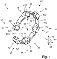
- FIG. 1 schematically shows a perspective side view of a guide ring for guiding two concentrically arranged components in a filling element according to a first embodiment.
- the guide ring 4 has a base body 40, which essentially has the shape of a circular ring segment or a circular arc segment 402.
- On the base body 40 there are a plurality of spaced apart, radially projecting areas 41 on a first side 43 of the base body 40 for sliding over a cylindrical surface and a plurality of spaced apart, radially projecting on a second side 44 opposite second side 44 arranged for radial and axial support against at least one support surface.
- a sliding area 41 and a support area 42 are arranged opposite each other at essentially the same location in the radial direction 44.
- the base body 40 thus has a plurality of knobs 48 which are highlighted radially inward and outward from the base body 40, each knob 48 having a sliding region 41 and a support region 42.
- the first side 43 corresponds to an inner side of the base body 40 when viewed in the radial direction 45 and the second side 44 correspondingly corresponds to an outer side of the base body 40 when viewed in the radial direction 45.
- the sliding areas 41 and the support areas 42 can be arranged the other way round if the first side corresponding to an outside of the base body 40 seen in the radial direction to the 40 and the second side corresponds to an inside of the base body 40 viewed in the radial direction 45.
- Each of the sliding areas 41 has a sliding surface 410 with which it is in contact with the cylindrical surface in the installed state in the filling element.
- each of the support regions 42 has two support surfaces 420, which are opposite one another, viewed in the axial direction 46, inclined to the axial direction 46, and rounded.
- the support surfaces 420 are designed such that radial support is possible via both support surfaces 420. They are also designed in such a way that axial support in a first direction is made possible via a first of the two support surfaces 420 and axial support in a second direction opposite to the first direction is made possible via a second of the two support surfaces 420. More on how to support the guide ring 4 in a filling element can be found below Figure 9 described.
- the guide ring 4 is formed in one piece and can be produced by means of injection molding or a 3D printing process.
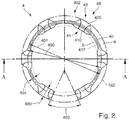
- Figure 2 shows schematically a top view of the guide ring 4 Figure 1 . It can be clearly seen here that the sliding surfaces 420 are arranged on a sliding pitch circle 412, viewed in the radial direction 45.
- the radius of the sliding part circle 412 is smaller than an inner radius 400 of the base body 40 in the form of an annular segment, so that the sliding regions 41 protrude inwards from the base body 40 in the radial direction 45.
- the support areas 42 extend up to a maximum diameter 482 of the guide ring 4, which is larger than an outer radius 401 of the base body 40 in the form of a circular ring segment. Accordingly, the support areas 42 partially protrude from the base body 40 in the radial direction to the base body 40. Accordingly, it follows that a width 404 of the base body 40 is smaller than a maximum width 480 of a knob 84. As a result, there are flow channels in the area of the base body 40 between the sliding circle 412 and the base body 40, and between the maximum diameter 482 and the base body 40 8 is provided, through which a fluid medium can flow in the axial direction 46 over the guide ring 4.
- the guide ring 4 is therefore suitable for use in a media channel, for example in a return gas channel or a purge channel of the filling element.
- the base body extends in a circular ring segment or circular arc segment 402. It therefore has an open area 403 when viewed in the circumferential direction 47.
- the open area 403 is greater than an increase in the length of the base body 40 in the circumferential direction 47, which occurs due to an increase in the temperature of the guide ring 4 in a predetermined temperature range.
- the provision of the open area 403 allows the base body 40 to lengthen correspondingly in the circumferential direction when the temperature increases, without the guide ring 4 necessarily expanding in the middle of an increase in diameter. Accordingly, the tolerances of the guide ring 4 on the sliding surfaces 410 and the supporting surfaces 420 can be chosen narrower than in the case of continuous guide rings.
- Figure 3 schematically shows a sectional view through the guide ring 4 Figure 2 along the in Figure 2 shown section line AA, which runs through two of the knobs 48.
- the support surfaces 420 which are inclined and rounded with respect to the axial direction 46 are arranged in such a way that the first support surface, here identified by the reference symbol 420, supports the alignment in FIG Figure 3 seen axially to the left, and by the second support surface, here designated by reference numeral 420 ', a support with respect to the orientation in FIG Figure 3 seen axially to the right is made possible. Due to the inclination of the two support surfaces 420, 420 ', radial support is also made possible.
- the knobs 48 have a width 480 which is greater than a width 404 of the base body 40, as a result of which the size of the flow channels 8 can be increased further and thus a resistance or a hindrance for the flow of a flow medium seen in the axial direction 46 through the guide ring 4 is reduced again when installed.
- the support areas 42 and the sliding areas 41 protrude on both sides as seen in the axial direction 46 from the base body 40.
- Figure 4 is a schematic sectional view of the guide ring 4 from Figure 2 shown. Since the guide ring 4 is cut over the entire surface in this view, the flow channels 8, which are provided between the material of the guide ring 4 and the sliding circle 410 and the maximum diameter 482, can again be seen particularly well.
- the guide ring 4 optionally has a maximum width 404 of the base body 40 perpendicular to the axial direction 46, which is less than or equal to 2/3 of the maximum width 480, in this case 1/4 of the width 480.
- the base body 40 has a maximum height 405 parallel to the axial direction 46, which corresponds to 3/5 the height 481.
- the width 404 and height 405 selected in this way ensure that the flow channels 8 are large enough not to significantly influence a flow of a flow medium, for example a cleaning fluid, in the axial direction 46.
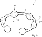
- FIGS Figures 5-7 a guide ring 4 for guiding a centering bell into a filling element according to a further embodiment is shown.
- the structure of the guide ring 4 corresponds essentially to that in FIGS Figures 1-4 shown.
- guide ring 4 support areas 42 on the support surfaces 420 have a double curvature.
- they are rounded on the one hand, like those in Figure 1 shown, and additionally provided with a curvature about an axis parallel to the axial direction 46, which is greater than a curvature predetermined by the maximum diameter 482, so that the support regions have an essentially hemispherical shape.
- the support surfaces 420 essentially form a point contact with the respective support surface in the installed state, so that the abrasion surface of the support region is particularly small.
- the sliding surfaces 410 of the sliding areas 41 have a concave curvature with a radius which is smaller than the radius of the sliding part circle 412.
- the radius of the sliding areas 41 can also be larger than the radius of the sliding part circle 412.
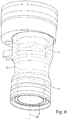
- FIG 8 a perspective side view of a filling element 1 for filling a container with a flowable filling material is shown schematically.
- the filling tube 1 is designed to fill a can or a bottle with a drink. It comprises a filling tube 3 for providing a filling material flow, the filling tube 3 corresponding to a second component of the filling element 1, and a centering bell 2, which extends radially outside the filling tube 3 and is movable relative to the filling tube 3 along a longitudinal axis 30 of the filling tube 3, for centering and or Sealing the container opening, the centering bell 2 being a first component of the filling element 1 corresponds.
- the filling element 1 also has guide rings 4, spaced apart from one another, between an outside of the filling tube 3 and an inside of the centering bell 22 for guiding the centering bell 2 relative to the filling tube 3.
- the guide rings 4 correspond to those in the Figures 1-4 described embodiment.
- the centering bell 2 is shown translucent or partially transparent, so that the view of the filling tube 3 and the guide rings 4 is made possible.
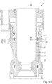
- Figure 9 schematically shows a sectional view through the filling element 1 Figure 8 . It can be clearly seen that there is a distance or an annular gap between the outside of the filling tube 3 and the inside of the centering bell 2, which in this embodiment provides a return gas channel 7 for gas or air displaced from the container during the filling of the container with the filling material .
- the guide rings 4 are arranged in the return gas duct 7.
- the sliding areas 41 of the guide rings 4 are in sliding contact with their cylindrical surfaces 5 on the outside of the filling tube 3 by means of their sliding surfaces 410.
- the centering bell 2 has two V-shaped grooves 20 which are designed such that the support areas 42 of the guide rings 4 can be accommodated.
- the V-shaped grooves 20 each have two mutually inclined support surfaces 6, wherein each support surface 6 is in contact with a support surface 420 of a knob 48.
- the guide ring 4 is fixed relative to the centering bell 2 both in the radial direction and in the axial direction.
- the centering bell 2 can be displaced with respect to the filling pipe 3 in the direction of the longitudinal axis 30, the guide rings 4 remaining in a fixed position relative to the centering bell 2 due to the reception in the grooves 20, and the assembly comprising the centering bell 2 and the guide rings 4 relative can move to the filling tube 3 in the direction of the longitudinal axis 30.
- the latter has a sealing ring 21 which is arranged on the upper end face of the centering bell 2 and is in sealing contact with a standing part of the filling element 1.
- valve body 31 In the interior of the filling tube 3, a valve body 31 is provided, which is arranged axially displaceable relative to the filling tube 3. This allows the valve body 31 relative to a valve seat 32 of the Filling tube 3 are moved to open or close a product flow channel 33 for the product.
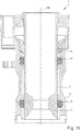
- Figure 10 is a schematic sectional view of the filling element from Figure 8 shown.
- the cut does not run through the knobs 48, as in FIG Figure 9 shown, but through the base body 40, so that the flow channels 8 provided radially inside and radially outside of the base body 40 by the guide ring 4 can be seen.
- An inner flow channel 8 extends between the cylindrical surface 5 of the filling tube 3 and the base body 40, and an outer flow channel 8 extends between the base body 40 and the V-shaped groove 20.
- the base body 40 has a shape of the guide ring 4 provided in an installation position, as shown in FIGS Figures 9 and 10th is shown, a radially outwardly expanded shape. This makes it possible to clip the guide rings 4 into the V-shaped grooves.
- the guide ring 4 is in its in the Figures 9 and 10th shown installation position in a state biased against the support surfaces 6 of the centering bell 2. Due to this preload, the guide ring is therefore securely in the V-shaped groove 20, even if the centering bell 2 is not mounted on the filling tube 3.
- Figure 11 shows schematically a sectional view through a filling element 1 for filling a container with a flowable filling material according to a further embodiment.
- the filling element 1 essentially corresponds to that in FIG Figure 8-10 shown, a swirl body 9 being provided in the upper region of the centering bell 2.
- the swirl body 9 is designed in the form of a raised edge on the inside of the centering bell 2, which is formed spirally with respect to the longitudinal axis 30.
Landscapes
- Engineering & Computer Science (AREA)
- General Engineering & Computer Science (AREA)
- Mechanical Engineering (AREA)
- Filling Of Jars Or Cans And Processes For Cleaning And Sealing Jars (AREA)
- Supply Of Fluid Materials To The Packaging Location (AREA)
- Basic Packing Technique (AREA)
Priority Applications (1)
| Application Number | Priority Date | Filing Date | Title |
|---|---|---|---|
| EP24197186.0A EP4446279A3 (fr) | 2018-12-03 | 2019-12-03 | Bague de guidage pour guider deux composants concentriques dans un organe de remplissage |
Applications Claiming Priority (1)
| Application Number | Priority Date | Filing Date | Title |
|---|---|---|---|
| DE102018130741.1A DE102018130741A1 (de) | 2018-12-03 | 2018-12-03 | Führungsring zum Führen zweier konzentrisch zueinander angeordneter Bauteile in einem Füllorgan und Füllorgan |
Related Child Applications (2)
| Application Number | Title | Priority Date | Filing Date |
|---|---|---|---|
| EP24197186.0A Division-Into EP4446279A3 (fr) | 2018-12-03 | 2019-12-03 | Bague de guidage pour guider deux composants concentriques dans un organe de remplissage |
| EP24197186.0A Division EP4446279A3 (fr) | 2018-12-03 | 2019-12-03 | Bague de guidage pour guider deux composants concentriques dans un organe de remplissage |
Publications (3)
| Publication Number | Publication Date |
|---|---|
| EP3677542A1 true EP3677542A1 (fr) | 2020-07-08 |
| EP3677542B1 EP3677542B1 (fr) | 2024-10-09 |
| EP3677542C0 EP3677542C0 (fr) | 2024-10-09 |
Family
ID=68766648
Family Applications (2)
| Application Number | Title | Priority Date | Filing Date |
|---|---|---|---|
| EP19213203.3A Active EP3677542B1 (fr) | 2018-12-03 | 2019-12-03 | Organe de remplissage avec anneau de guidage permettant de guider deux composants disposés concentriquement l'un par rapport à l'autre |
| EP24197186.0A Pending EP4446279A3 (fr) | 2018-12-03 | 2019-12-03 | Bague de guidage pour guider deux composants concentriques dans un organe de remplissage |
Family Applications After (1)
| Application Number | Title | Priority Date | Filing Date |
|---|---|---|---|
| EP24197186.0A Pending EP4446279A3 (fr) | 2018-12-03 | 2019-12-03 | Bague de guidage pour guider deux composants concentriques dans un organe de remplissage |
Country Status (3)
| Country | Link |
|---|---|
| EP (2) | EP3677542B1 (fr) |
| CN (1) | CN111252717B (fr) |
| DE (1) | DE102018130741A1 (fr) |
Citations (5)
| Publication number | Priority date | Publication date | Assignee | Title |
|---|---|---|---|---|
| DE2638749A1 (de) * | 1975-08-29 | 1977-03-10 | Pont A Mousson | Vorrichtung zum automatischen fuellen von flaschen bei gleichbleibendem druck |
| DE8029789U1 (de) * | 1980-11-07 | 1982-02-11 | Hans Grohe Gmbh & Co Kg, 7622 Schiltach | Gleit- und Führungsring aus Kunststoff |
| DE3244383A1 (de) * | 1982-12-01 | 1984-06-07 | Friedrich Grohe Armaturenfabrik Gmbh & Co, 5870 Hemer | Kugelgelenklagerung |
| DE102008011109A1 (de) * | 2008-02-26 | 2009-09-03 | Khs Ag | Füllelement zum Füllen von Behältern mit einem flüssigen Füllgut, sowie Füllmaschine |
| DE102013106104A1 (de) * | 2013-06-12 | 2014-12-18 | Krones Ag | Vorrichtung und Verfahren zum Befüllen eines Behälters mit einem Füllprodukt |
Family Cites Families (5)
| Publication number | Priority date | Publication date | Assignee | Title |
|---|---|---|---|---|
| US4688608A (en) * | 1986-04-21 | 1987-08-25 | Figgie International, Inc. | Filling valves for cans and like containers |
| DE102012014957A1 (de) * | 2012-07-30 | 2014-05-15 | Khs Gmbh | Füllelement sowie Füllmaschine |
| DE102014114708A1 (de) * | 2014-10-10 | 2016-04-14 | Krones Ag | Füllventil zum Befüllen eines Behälters mit einem Füllprodukt |
| CN205740321U (zh) * | 2016-05-11 | 2016-11-30 | 安徽慧创科技有限公司 | 一种自动灌装头 |
| DE102016008986A1 (de) * | 2016-07-22 | 2018-01-25 | Diehl Metall Stiftung & Co. Kg | Synchronring |
-
2018
- 2018-12-03 DE DE102018130741.1A patent/DE102018130741A1/de not_active Withdrawn
-
2019
- 2019-11-26 CN CN201911175086.0A patent/CN111252717B/zh active Active
- 2019-12-03 EP EP19213203.3A patent/EP3677542B1/fr active Active
- 2019-12-03 EP EP24197186.0A patent/EP4446279A3/fr active Pending
Patent Citations (5)
| Publication number | Priority date | Publication date | Assignee | Title |
|---|---|---|---|---|
| DE2638749A1 (de) * | 1975-08-29 | 1977-03-10 | Pont A Mousson | Vorrichtung zum automatischen fuellen von flaschen bei gleichbleibendem druck |
| DE8029789U1 (de) * | 1980-11-07 | 1982-02-11 | Hans Grohe Gmbh & Co Kg, 7622 Schiltach | Gleit- und Führungsring aus Kunststoff |
| DE3244383A1 (de) * | 1982-12-01 | 1984-06-07 | Friedrich Grohe Armaturenfabrik Gmbh & Co, 5870 Hemer | Kugelgelenklagerung |
| DE102008011109A1 (de) * | 2008-02-26 | 2009-09-03 | Khs Ag | Füllelement zum Füllen von Behältern mit einem flüssigen Füllgut, sowie Füllmaschine |
| DE102013106104A1 (de) * | 2013-06-12 | 2014-12-18 | Krones Ag | Vorrichtung und Verfahren zum Befüllen eines Behälters mit einem Füllprodukt |
Also Published As
| Publication number | Publication date |
|---|---|
| DE102018130741A1 (de) | 2020-06-04 |
| CN111252717B (zh) | 2022-01-28 |
| EP3677542B1 (fr) | 2024-10-09 |
| EP4446279A3 (fr) | 2024-12-25 |
| CN111252717A (zh) | 2020-06-09 |
| EP3677542C0 (fr) | 2024-10-09 |
| EP4446279A2 (fr) | 2024-10-16 |
Similar Documents
| Publication | Publication Date | Title |
|---|---|---|
| DE60220437T2 (de) | Durchflusskontrollvorrichtung, insbesondere zum medizinischen gebrauch | |
| EP2593997B1 (fr) | Dispositif de fixation d'un câble sur un raccord de départ de câble | |
| DE2058203C2 (de) | Rohrverbinder | |
| DE3515990C2 (de) | Ventilanordnung | |
| DE3517488A1 (de) | Rohranschluss, insbesondere fuer einen wasserkasten eines waermetauschers einer kraftfahrzeugheizung | |
| DE3002715C2 (de) | Dichtungsanordnung | |
| EP2252813B1 (fr) | Soupape à double siège, permettant le nettoyage des sièges, avec un dispositif de nettoyage pour une traversée du boîtier | |
| EP3184863B1 (fr) | Soufflet a membrane | |
| DE2839774A1 (de) | Vorrichtung zur einstellung des durchflussquerschnitts eines ventils | |
| EP0344584A2 (fr) | Dispositif de joint d'étanchéité | |
| DE2133422A1 (de) | Druckminderventil | |
| EP3239575B1 (fr) | Ensemble vanne à cage comprenant des anneaux d'étranglement | |
| DE3108051C2 (de) | Entspannungsventil | |
| DE2712818B2 (de) | Rohrförmiger Körper | |
| DE19929536C1 (de) | Anordnung zur axialen Festlegung des Ringes eines Lagers | |
| DE3141416C2 (de) | Vorrichtung zur Befestigung eines Deckels auf einem Gehäuse, insbesondere einem Ventilgehäuse | |
| DE102012222339A1 (de) | Fluiddrehdurchführung | |
| EP3677542B1 (fr) | Organe de remplissage avec anneau de guidage permettant de guider deux composants disposés concentriquement l'un par rapport à l'autre | |
| WO2020011502A1 (fr) | Dispositif distributeur rotatif doté d'un agencement d'étanchéité | |
| EP1116905A2 (fr) | Dispositif d'étanchéité | |
| DE69715919T2 (de) | Plattenwärmetauscher | |
| DE2607424C3 (de) | Zugfeste Verbindung zweier Muffenrohrleitungselemente | |
| DE2626668C2 (de) | Rohr- oder Schlauchleitungskupplung | |
| DE102011005675A1 (de) | Schaltvorrichtung | |
| EP0077058B1 (fr) | Robinet à boisseau sphérique |
Legal Events
| Date | Code | Title | Description |
|---|---|---|---|
| PUAI | Public reference made under article 153(3) epc to a published international application that has entered the european phase |
Free format text: ORIGINAL CODE: 0009012 |
|
| STAA | Information on the status of an ep patent application or granted ep patent |
Free format text: STATUS: THE APPLICATION HAS BEEN PUBLISHED |
|
| AK | Designated contracting states |
Kind code of ref document: A1 Designated state(s): AL AT BE BG CH CY CZ DE DK EE ES FI FR GB GR HR HU IE IS IT LI LT LU LV MC MK MT NL NO PL PT RO RS SE SI SK SM TR |
|
| AX | Request for extension of the european patent |
Extension state: BA ME |
|
| STAA | Information on the status of an ep patent application or granted ep patent |
Free format text: STATUS: REQUEST FOR EXAMINATION WAS MADE |
|
| 17P | Request for examination filed |
Effective date: 20210108 |
|
| RBV | Designated contracting states (corrected) |
Designated state(s): AL AT BE BG CH CY CZ DE DK EE ES FI FR GB GR HR HU IE IS IT LI LT LU LV MC MK MT NL NO PL PT RO RS SE SI SK SM TR |
|
| STAA | Information on the status of an ep patent application or granted ep patent |
Free format text: STATUS: EXAMINATION IS IN PROGRESS |
|
| 17Q | First examination report despatched |
Effective date: 20220615 |
|
| P01 | Opt-out of the competence of the unified patent court (upc) registered |
Effective date: 20230523 |
|
| GRAP | Despatch of communication of intention to grant a patent |
Free format text: ORIGINAL CODE: EPIDOSNIGR1 |
|
| STAA | Information on the status of an ep patent application or granted ep patent |
Free format text: STATUS: GRANT OF PATENT IS INTENDED |
|
| INTG | Intention to grant announced |
Effective date: 20240430 |
|
| GRAS | Grant fee paid |
Free format text: ORIGINAL CODE: EPIDOSNIGR3 |
|
| GRAA | (expected) grant |
Free format text: ORIGINAL CODE: 0009210 |
|
| STAA | Information on the status of an ep patent application or granted ep patent |
Free format text: STATUS: THE PATENT HAS BEEN GRANTED |
|
| AK | Designated contracting states |
Kind code of ref document: B1 Designated state(s): AL AT BE BG CH CY CZ DE DK EE ES FI FR GB GR HR HU IE IS IT LI LT LU LV MC MK MT NL NO PL PT RO RS SE SI SK SM TR |
|
| REG | Reference to a national code |
Ref country code: CH Ref legal event code: EP |
|
| REG | Reference to a national code |
Ref country code: DE Ref legal event code: R096 Ref document number: 502019012251 Country of ref document: DE |
|
| REG | Reference to a national code |
Ref country code: IE Ref legal event code: FG4D Free format text: LANGUAGE OF EP DOCUMENT: GERMAN |
|
| U01 | Request for unitary effect filed |
Effective date: 20241028 |
|
| P04 | Withdrawal of opt-out of the competence of the unified patent court (upc) registered |
Free format text: CASE NUMBER: APP_59925/2024 Effective date: 20241105 |
|
| U07 | Unitary effect registered |
Designated state(s): AT BE BG DE DK EE FI FR IT LT LU LV MT NL PT RO SE SI Effective date: 20241108 |
|
| U20 | Renewal fee for the european patent with unitary effect paid |
Year of fee payment: 6 Effective date: 20241107 |
|
| U1N | Appointed representative for the unitary patent procedure changed after the registration of the unitary effect |
Representative=s name: NORDMEYER, PHILIPP WERNER; DE |
|
| PG25 | Lapsed in a contracting state [announced via postgrant information from national office to epo] |
Ref country code: HR Free format text: LAPSE BECAUSE OF FAILURE TO SUBMIT A TRANSLATION OF THE DESCRIPTION OR TO PAY THE FEE WITHIN THE PRESCRIBED TIME-LIMIT Effective date: 20241009 Ref country code: IS Free format text: LAPSE BECAUSE OF FAILURE TO SUBMIT A TRANSLATION OF THE DESCRIPTION OR TO PAY THE FEE WITHIN THE PRESCRIBED TIME-LIMIT Effective date: 20250209 |
|
| PG25 | Lapsed in a contracting state [announced via postgrant information from national office to epo] |
Ref country code: ES Free format text: LAPSE BECAUSE OF FAILURE TO SUBMIT A TRANSLATION OF THE DESCRIPTION OR TO PAY THE FEE WITHIN THE PRESCRIBED TIME-LIMIT Effective date: 20241009 |
|
| PG25 | Lapsed in a contracting state [announced via postgrant information from national office to epo] |
Ref country code: NO Free format text: LAPSE BECAUSE OF FAILURE TO SUBMIT A TRANSLATION OF THE DESCRIPTION OR TO PAY THE FEE WITHIN THE PRESCRIBED TIME-LIMIT Effective date: 20250109 |
|
| PG25 | Lapsed in a contracting state [announced via postgrant information from national office to epo] |
Ref country code: GR Free format text: LAPSE BECAUSE OF FAILURE TO SUBMIT A TRANSLATION OF THE DESCRIPTION OR TO PAY THE FEE WITHIN THE PRESCRIBED TIME-LIMIT Effective date: 20250110 |
|
| PG25 | Lapsed in a contracting state [announced via postgrant information from national office to epo] |
Ref country code: PL Free format text: LAPSE BECAUSE OF FAILURE TO SUBMIT A TRANSLATION OF THE DESCRIPTION OR TO PAY THE FEE WITHIN THE PRESCRIBED TIME-LIMIT Effective date: 20241009 |
|
| PG25 | Lapsed in a contracting state [announced via postgrant information from national office to epo] |
Ref country code: RS Free format text: LAPSE BECAUSE OF FAILURE TO SUBMIT A TRANSLATION OF THE DESCRIPTION OR TO PAY THE FEE WITHIN THE PRESCRIBED TIME-LIMIT Effective date: 20250109 |
|
| PG25 | Lapsed in a contracting state [announced via postgrant information from national office to epo] |
Ref country code: SM Free format text: LAPSE BECAUSE OF FAILURE TO SUBMIT A TRANSLATION OF THE DESCRIPTION OR TO PAY THE FEE WITHIN THE PRESCRIBED TIME-LIMIT Effective date: 20241009 |
|
| PG25 | Lapsed in a contracting state [announced via postgrant information from national office to epo] |
Ref country code: MC Free format text: LAPSE BECAUSE OF FAILURE TO SUBMIT A TRANSLATION OF THE DESCRIPTION OR TO PAY THE FEE WITHIN THE PRESCRIBED TIME-LIMIT Effective date: 20241009 |
|
| PG25 | Lapsed in a contracting state [announced via postgrant information from national office to epo] |
Ref country code: SK Free format text: LAPSE BECAUSE OF FAILURE TO SUBMIT A TRANSLATION OF THE DESCRIPTION OR TO PAY THE FEE WITHIN THE PRESCRIBED TIME-LIMIT Effective date: 20241009 |
|
| PG25 | Lapsed in a contracting state [announced via postgrant information from national office to epo] |
Ref country code: CZ Free format text: LAPSE BECAUSE OF FAILURE TO SUBMIT A TRANSLATION OF THE DESCRIPTION OR TO PAY THE FEE WITHIN THE PRESCRIBED TIME-LIMIT Effective date: 20241009 |
|
| REG | Reference to a national code |
Ref country code: CH Ref legal event code: PL |
|
| PLBE | No opposition filed within time limit |
Free format text: ORIGINAL CODE: 0009261 |
|
| STAA | Information on the status of an ep patent application or granted ep patent |
Free format text: STATUS: NO OPPOSITION FILED WITHIN TIME LIMIT |
|
| 26N | No opposition filed |
Effective date: 20250710 |
|
| GBPC | Gb: european patent ceased through non-payment of renewal fee |
Effective date: 20250109 |
|
| PG25 | Lapsed in a contracting state [announced via postgrant information from national office to epo] |
Ref country code: GB Free format text: LAPSE BECAUSE OF NON-PAYMENT OF DUE FEES Effective date: 20250109 |
|
| PG25 | Lapsed in a contracting state [announced via postgrant information from national office to epo] |
Ref country code: CH Free format text: LAPSE BECAUSE OF NON-PAYMENT OF DUE FEES Effective date: 20241231 |
|
| PG25 | Lapsed in a contracting state [announced via postgrant information from national office to epo] |
Ref country code: IE Free format text: LAPSE BECAUSE OF NON-PAYMENT OF DUE FEES Effective date: 20241203 |
|
| U20 | Renewal fee for the european patent with unitary effect paid |
Year of fee payment: 7 Effective date: 20251110 |
|
| PG25 | Lapsed in a contracting state [announced via postgrant information from national office to epo] |
Ref country code: CY Free format text: LAPSE BECAUSE OF FAILURE TO SUBMIT A TRANSLATION OF THE DESCRIPTION OR TO PAY THE FEE WITHIN THE PRESCRIBED TIME-LIMIT; INVALID AB INITIO Effective date: 20191203 |