EP3677778A1 - Elektrische ölpumpe - Google Patents
Elektrische ölpumpe Download PDFInfo
- Publication number
- EP3677778A1 EP3677778A1 EP18849856.2A EP18849856A EP3677778A1 EP 3677778 A1 EP3677778 A1 EP 3677778A1 EP 18849856 A EP18849856 A EP 18849856A EP 3677778 A1 EP3677778 A1 EP 3677778A1
- Authority
- EP
- European Patent Office
- Prior art keywords
- housing
- heat dissipating
- pump
- oil pump
- cavity
- Prior art date
- Legal status (The legal status is an assumption and is not a legal conclusion. Google has not performed a legal analysis and makes no representation as to the accuracy of the status listed.)
- Pending
Links
Images


Classifications
-
- F—MECHANICAL ENGINEERING; LIGHTING; HEATING; WEAPONS; BLASTING
- F04—POSITIVE - DISPLACEMENT MACHINES FOR LIQUIDS; PUMPS FOR LIQUIDS OR ELASTIC FLUIDS
- F04B—POSITIVE-DISPLACEMENT MACHINES FOR LIQUIDS; PUMPS
- F04B17/00—Pumps characterised by combination with, or adaptation to, specific driving engines or motors
- F04B17/03—Pumps characterised by combination with, or adaptation to, specific driving engines or motors driven by electric motors
-
- F—MECHANICAL ENGINEERING; LIGHTING; HEATING; WEAPONS; BLASTING
- F04—POSITIVE - DISPLACEMENT MACHINES FOR LIQUIDS; PUMPS FOR LIQUIDS OR ELASTIC FLUIDS
- F04C—ROTARY-PISTON, OR OSCILLATING-PISTON, POSITIVE-DISPLACEMENT MACHINES FOR LIQUIDS; ROTARY-PISTON, OR OSCILLATING-PISTON, POSITIVE-DISPLACEMENT PUMPS
- F04C2/00—Rotary-piston machines or pumps
- F04C2/08—Rotary-piston machines or pumps of intermeshing-engagement type, i.e. with engagement of co-operating members similar to that of toothed gearing
-
- F—MECHANICAL ENGINEERING; LIGHTING; HEATING; WEAPONS; BLASTING
- F04—POSITIVE - DISPLACEMENT MACHINES FOR LIQUIDS; PUMPS FOR LIQUIDS OR ELASTIC FLUIDS
- F04B—POSITIVE-DISPLACEMENT MACHINES FOR LIQUIDS; PUMPS
- F04B15/00—Pumps adapted to handle specific fluids, e.g. by selection of specific materials for pumps or pump parts
- F04B15/02—Pumps adapted to handle specific fluids, e.g. by selection of specific materials for pumps or pump parts the fluids being viscous or non-homogeneous
-
- F—MECHANICAL ENGINEERING; LIGHTING; HEATING; WEAPONS; BLASTING
- F04—POSITIVE - DISPLACEMENT MACHINES FOR LIQUIDS; PUMPS FOR LIQUIDS OR ELASTIC FLUIDS
- F04B—POSITIVE-DISPLACEMENT MACHINES FOR LIQUIDS; PUMPS
- F04B53/00—Component parts, details or accessories not provided for in, or of interest apart from, groups F04B1/00 - F04B23/00 or F04B39/00 - F04B47/00
- F04B53/08—Cooling; Heating; Preventing freezing
-
- F—MECHANICAL ENGINEERING; LIGHTING; HEATING; WEAPONS; BLASTING
- F04—POSITIVE - DISPLACEMENT MACHINES FOR LIQUIDS; PUMPS FOR LIQUIDS OR ELASTIC FLUIDS
- F04C—ROTARY-PISTON, OR OSCILLATING-PISTON, POSITIVE-DISPLACEMENT MACHINES FOR LIQUIDS; ROTARY-PISTON, OR OSCILLATING-PISTON, POSITIVE-DISPLACEMENT PUMPS
- F04C11/00—Combinations of two or more machines or pumps, each being of rotary-piston or oscillating-piston type; Pumping installations
-
- F—MECHANICAL ENGINEERING; LIGHTING; HEATING; WEAPONS; BLASTING
- F04—POSITIVE - DISPLACEMENT MACHINES FOR LIQUIDS; PUMPS FOR LIQUIDS OR ELASTIC FLUIDS
- F04C—ROTARY-PISTON, OR OSCILLATING-PISTON, POSITIVE-DISPLACEMENT MACHINES FOR LIQUIDS; ROTARY-PISTON, OR OSCILLATING-PISTON, POSITIVE-DISPLACEMENT PUMPS
- F04C15/00—Component parts, details or accessories of machines, pumps or pumping installations, not provided for in groups F04C2/00 - F04C14/00
- F04C15/0096—Heating; Cooling
-
- F—MECHANICAL ENGINEERING; LIGHTING; HEATING; WEAPONS; BLASTING
- F04—POSITIVE - DISPLACEMENT MACHINES FOR LIQUIDS; PUMPS FOR LIQUIDS OR ELASTIC FLUIDS
- F04C—ROTARY-PISTON, OR OSCILLATING-PISTON, POSITIVE-DISPLACEMENT MACHINES FOR LIQUIDS; ROTARY-PISTON, OR OSCILLATING-PISTON, POSITIVE-DISPLACEMENT PUMPS
- F04C2/00—Rotary-piston machines or pumps
- F04C2/08—Rotary-piston machines or pumps of intermeshing-engagement type, i.e. with engagement of co-operating members similar to that of toothed gearing
- F04C2/082—Details specially related to intermeshing engagement type machines or pumps
- F04C2/086—Carter
-
- F—MECHANICAL ENGINEERING; LIGHTING; HEATING; WEAPONS; BLASTING
- F04—POSITIVE - DISPLACEMENT MACHINES FOR LIQUIDS; PUMPS FOR LIQUIDS OR ELASTIC FLUIDS
- F04C—ROTARY-PISTON, OR OSCILLATING-PISTON, POSITIVE-DISPLACEMENT MACHINES FOR LIQUIDS; ROTARY-PISTON, OR OSCILLATING-PISTON, POSITIVE-DISPLACEMENT PUMPS
- F04C2/00—Rotary-piston machines or pumps
- F04C2/08—Rotary-piston machines or pumps of intermeshing-engagement type, i.e. with engagement of co-operating members similar to that of toothed gearing
- F04C2/10—Rotary-piston machines or pumps of intermeshing-engagement type, i.e. with engagement of co-operating members similar to that of toothed gearing of internal-axis type with the outer member having more teeth or tooth-equivalents, e.g. rollers, than the inner member
-
- F—MECHANICAL ENGINEERING; LIGHTING; HEATING; WEAPONS; BLASTING
- F04—POSITIVE - DISPLACEMENT MACHINES FOR LIQUIDS; PUMPS FOR LIQUIDS OR ELASTIC FLUIDS
- F04C—ROTARY-PISTON, OR OSCILLATING-PISTON, POSITIVE-DISPLACEMENT MACHINES FOR LIQUIDS; ROTARY-PISTON, OR OSCILLATING-PISTON, POSITIVE-DISPLACEMENT PUMPS
- F04C29/00—Component parts, details or accessories of pumps or pumping installations, not provided for in groups F04C18/00 - F04C28/00
- F04C29/04—Heating; Cooling; Heat insulation
- F04C29/047—Cooling of electronic devices installed inside the pump housing, e.g. inverters
-
- F—MECHANICAL ENGINEERING; LIGHTING; HEATING; WEAPONS; BLASTING
- F16—ENGINEERING ELEMENTS AND UNITS; GENERAL MEASURES FOR PRODUCING AND MAINTAINING EFFECTIVE FUNCTIONING OF MACHINES OR INSTALLATIONS; THERMAL INSULATION IN GENERAL
- F16N—LUBRICATING
- F16N13/00—Lubricating-pumps
- F16N13/20—Rotary pumps
-
- H—ELECTRICITY
- H02—GENERATION; CONVERSION OR DISTRIBUTION OF ELECTRIC POWER
- H02K—DYNAMO-ELECTRIC MACHINES
- H02K5/00—Casings; Enclosures; Supports
- H02K5/04—Casings or enclosures characterised by the shape, form or construction thereof
- H02K5/18—Casings or enclosures characterised by the shape, form or construction thereof with ribs or fins for improving heat transfer
-
- F—MECHANICAL ENGINEERING; LIGHTING; HEATING; WEAPONS; BLASTING
- F04—POSITIVE - DISPLACEMENT MACHINES FOR LIQUIDS; PUMPS FOR LIQUIDS OR ELASTIC FLUIDS
- F04C—ROTARY-PISTON, OR OSCILLATING-PISTON, POSITIVE-DISPLACEMENT MACHINES FOR LIQUIDS; ROTARY-PISTON, OR OSCILLATING-PISTON, POSITIVE-DISPLACEMENT PUMPS
- F04C2240/00—Components
- F04C2240/30—Casings or housings
-
- F—MECHANICAL ENGINEERING; LIGHTING; HEATING; WEAPONS; BLASTING
- F04—POSITIVE - DISPLACEMENT MACHINES FOR LIQUIDS; PUMPS FOR LIQUIDS OR ELASTIC FLUIDS
- F04C—ROTARY-PISTON, OR OSCILLATING-PISTON, POSITIVE-DISPLACEMENT MACHINES FOR LIQUIDS; ROTARY-PISTON, OR OSCILLATING-PISTON, POSITIVE-DISPLACEMENT PUMPS
- F04C2240/00—Components
- F04C2240/80—Other components
- F04C2240/808—Electronic circuits (e.g. inverters) installed inside the machine
Definitions
- the present disclosure relates to the field of vehicles, and in particular to a component of a lubrication system and/or a cooling system of a vehicle.
- the electric oil pump is mainly configured to provide a power source for the lubrication system and/or the cooling system of the vehicle, and includes a stator assembly.
- the stator assembly generates heat during operation. If the heat is accumulated to a certain amount and cannot be dissipated in time, it will affect the performance of the stator assembly, thereby reducing the service life of the electric oil pump.
- One object of the present disclosure is to provide an electric oil pump, which facilitates heat dissipation of the stator assembly and thereby facilitates improving the service life of the electric oil pump.
- An electric oil pump which includes a pump housing, a pump rotor assembly, a stator assembly, a motor rotor assembly, and an electric control board.
- the pump housing defines a pump cavity, the pump cavity includes a first cavity and a second cavity, the pump rotor assembly is arranged in the first cavity, and the stator assembly, the motor rotor assembly and the electric control board are arranged in the second cavity,
- the pump housing includes a first housing, the first housing includes a side wall, the side wall includes an inner surface and an outer surface, at least a part of the inner surface is arranged in contact with at least a part of an outer wall of the stator assembly, the outer surface is provided with or shaped with a first heat dissipating portion, and at least a part of the first heat dissipating portion covers at least a part of an outer circumference of the stator assembly in a circumferential direction of the electric oil pump, which facilitates heat dissipation of the stator assembly and thereby facilitates improving the service life
- An electric oil pump which includes a pump housing, a pump rotor assembly, a stator assembly, a motor rotor assembly, and an electric control board.
- the pump housing defines a pump cavity, the pump cavity includes a first cavity and a second cavity, the pump rotor assembly is arranged in the first cavity, the stator assembly, the motor rotor assembly and the electric control board are arranged in the second cavity, the pump housing includes a first housing, the first housing includes a side wall, the side wall includes an inner surface and an outer surface, at least a part of the inner surface is arranged in contact with at least a part of an outer wall of the stator assembly, the outer surface is provided with or shaped with a first heat dissipating portion, the first housing includes a hollow portion, a hollow cavity is formed in the hollow portion, the stator assembly and the motor rotor assembly are arranged in the hollow cavity, the stator assembly includes a coil, the coil includes a first top and a first bottom, the first top is closer to the pump rot
- the electric oil pump according to this embodiment is primarily configured to provide flowing power to a working medium of the lubrication system and/or the cooling system of the vehicle, in particular to provide flowing power to the working medium of the lubrication system and/or the cooling system in the vehicle transmission system.
- the electric oil pump 100 includes a pump housing, a motor rotor assembly 3, a stator assembly 4, a pump shaft 5, a pump rotor assembly 8 and an electric control board 6;
- the pump housing defines a pump cavity
- the motor rotor assembly 3, the stator assembly 4, the pump shaft 5, the pump rotor assembly 8, and the electric control board 6 are accommodated in the pump cavity
- the stator assembly 4 includes a stator core 41 and a coil 42.
- the electric control board 6 is configured to control a current passing through the coil 42 of the stator assembly 4 to change according to a certain law, thereby controlling the stator assembly 4 to generate an ever-changing excitation magnetic field, and the motor rotor assembly 3 is rotated under the effect of the excitation magnetic field.
- the motor rotor assembly 3 drives the pump rotor assembly 8 to rotate.
- the pump rotor assembly 8 rotates, the volume of the pump cavity changes, so that the working medium is pushed out to an outlet to generate flowing power.
- the pump housing includes a pump cover 1, a first housing 2 and a second housing 7, and the pump cover 11, the first housing 2 and the second housing 7 are relatively fixedly connected;
- the pump housing defines a pump cavity, the pump cavity includes a first cavity 80 and a second cavity 90, the first cavity 80 has a working medium flowing through, and the pump rotor assembly 8 and the electric control board 6 are arranged in the first cavity 80;
- the second cavity 90 has no working medium passing through, and the stator assembly 4, the motor rotor assembly 3 and the electric control board 6 are arranged in the second cavity 90; thus, the stator assembly 4 and the electric control board 6 are sufficiently separated from the working medium, thereby ensuring that the performance of the stator assembly and the electric control board is not affected by the working medium.
- the electric oil pump 100 includes a pump rotor assembly 8, and the pump rotor assembly 8 includes an inner rotor 81 and an outer rotor 82.
- the inner rotor 81 includes multiple external teeth
- the outer rotor 82 includes multiple internal teeth
- a hydraulic cavity 801 is formed between the multiple internal teeth of the outer rotor 82 and the multiple external teeth of the inner rotor 81.
- the outer rotor 82 is sleeved on an outer circumference of the inner rotor 81, and a part of the multiple internal teeth of the outer rotor 82 are internally meshed with a part of the multiple external teeth of the inner rotor 81.
- the electric oil pump includes an inlet 11 and an outlet 12, and the working medium can enter the hydraulic cavity 801 through the inlet 11, and then exit the hydraulic cavity 801 through the outlet 12; and due to the fact that a part of the multiple external teeth of the inner rotor 81 are meshed with a part of the multiple internal teeth of the outer rotor 82, the outer rotor 82 is driven to rotate when the inner rotor 81 rotates.
- the internal volume of the hydraulic cavity 801 changes as there is a certain eccentric distance between the inner rotor 81 and the outer rotor 82.
- the internal volume of the hydraulic cavity 801 is gradually increased to form a partial vacuum, and the working medium is drawn into the hydraulic cavity 801 through the inlet 11; and when the pump rotor continues to rotate, the volume of the hydraulic cavity previously filled with the working medium is gradually reduced, and the working medium is squeezed, so that the working medium in the hydraulic cavity 801 is pushed to the outlet 12, thereby generating the flowing power.
- the pump cover 1 is fixedly connected to the first housing 2, and the first housing 2 is fixedly connected to the second housing 7.
- the pump cover 1 and the first housing 2 are connected by screws or bolts, such that the electric oil pump is more convenient to disassemble and assemble, thereby facilitating the maintenance of the pump rotor assembly in the electric oil pump.
- the pump cover 1 and the first housing 2 can also be connected by other means, such as plugging-in and snap-fit.
- the first housing 2 is fixedly connected to the second housing 7, and specifically, the first housing 2 and the second housing 7 are connected by screws or bolts, which, on one hand, renders the electric oil pump more convenient to disassemble and assemble, thereby facilitating the maintenance of the electric control board in the electric oil pump, and on the other hand, renders the connection between the first housing 2 and the second housing 7 more reliable.
- the first housing 2 and the second housing 7 can also be connected by plugging-in, snap-fit or other connection means.
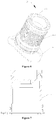
- Figures 6 to 9 are schematic views showing the structure of the first housing according to a first embodiment
- Figure 7 is a schematic view showing the structure of the first housing not provided with a first heat dissipating portion.
- the first housing according to the first embodiment will be described hereinafter.
- the first housing 2 includes a side wall 21 including an inner surface 211 and an outer surface 212.
- the inner surface 211 is arranged in contact with at least a part of an outer wall of the stator assembly 4, the outer surface 212 is provided with a first heat dissipating portion 26, at least a part of the first heat dissipating portion 26 covers at least a part of an outer circumference of the stator assembly 4 in a circumferential direction of the electric oil pump.
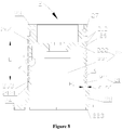
- the first housing 2 includes a hollow portion 22, and the hollow cavity 221 is formed in the hollow portion.
- the stator assembly and the motor rotor assembly in Figure 2 are arranged in the hollow cavity 221, and at least a part of the longitudinal distribution region of the first heat dissipating portion 26 is located in a portion of the first housing 2 corresponding to the hollow cavity 221, such that at least a part of the longitudinal distribution region of the first heat dissipating portion 26 is arranged corresponding to at least a part of the first housing 2 corresponding to the hollow cavity 221, which facilitates the heat dissipation of the stator assembly and the electric control board.
- the hollow portion 22 includes a first surface 222 and a second surface 223, the first surface 222 is a top surface of the hollow portion 22, and the second surface 223 is a bottom surface of the hollow portion.
- the first surface 222 is closer to the pump rotor assembly 8 than the second surface 223.
- a first reference surface is defined to have a central axis coinciding with that of the first surface 222 and coincide with the first surface
- a second reference surface is defined to have a central axis coinciding with that of the second surface 223 and coincide with the second surface 223.
- at least a part of the longitudinal distribution region of the first heat dissipating portion 26 is located between the first reference surface and the second reference surface along a central axis direction of the electric oil pump.
- the coil 42 includes a first top 421 and a first bottom 422, the first top 421 is closer to the pump rotor assembly 8 than the first bottom 422, the first heat dissipating portion 26 includes a start portion 264 and an end portion 263, along the central axis direction of the electric oil pump 100, the start portion 264 is closer to the pump rotor assembly 8 in Figure 3 than the end portion 263; along the central axis direction of the electric oil pump 100, the first top 421 of the coil 42 in Figure 3 is closer to the pump rotor assembly 8 than the end portion 263 of the first heat dissipating portion 26, that is, the end portion 263 of the first heat dissipating portion 26 is located below the first top 421 of the coil 42 in Figure 3 .
- FIG 8 an area of a projection of the first heat dissipating portion 26 onto the outer surface 212 of a corresponding side wall 21 is referred to as a first area, a surface area of the first heat dissipating portion 26 is referred to as a second area, and the second area is larger than or equal to the first area.
- Figure 7 is a schematic view showing the structure of the first housing not provided with the first heat dissipating portion on the outer surface. Given a defined surface K, the defined surface K is an outer surface not provided with the first heat dissipating portion 26, and the outer surface 212' in Figure 7 may be fitted to Figure 8 to obtain the defined surface K (indicated by the dashed line in Figure 8 ).
- the first heat dissipating portion 26 includes multiple convex portions 262 which protrude away from a central axis of the first housing 2.
- the convex portions 262 so protrude away from the outer surface 212 as to be tangent to the defined surface K. In this way, a heat dissipation area of the first housing 2 is increased by such means as equivalent to peeling, thereby facilitating heat dissipation of the stator assembly and the electric control board.
- the convex portions 262 are spaced apart or continuously distributed along the central axis direction of the first housing 2.
- the first heat dissipating portion 26 further includes multiple concave portions 261, the multiple concave portions 261 are concaved from the outer surface 212 toward the central axis of the first housing 2, and the convex portions 262 and the concave portions 261 are distributed along the axial direction of the electric oil pump.
- the convex portions 262 are spaced apart from each other along the central axis direction of the first housing 2, where the term “spaced apart” means that the concave portions 261 and the convex portions 262 are alternately arranged, that is, a convex portion 262 is provided between each two adjacent concave portions 261, or a concave portion 261 is provided between each two adjacent convex portions 262.
- the concave portions 261 are arranged along the axial direction of the electric oil pump, so that the heat dissipation area is maximized, which facilitates the heat dissipation of the stator assembly 4 and the electric control board 6 in Figure 2 , thereby facilitating improving the service life of the electric oil pump.
- the convex portions 262 can also be continuously distributed along the central axis direction of the first housing 2, where the term “continuously distributed” means that the convex portions 262 are connected end to end.
- the multiple convex portions 262 have the same convex height
- a wall thickness H1 of the first housing 2 at the convex portion 262 is larger than or equal to 1.5 times the convex height of the convex portion 262, which can ensure the mechanical strength of the side wall 21 of the first housing 2 at the convex portions 262
- a wall thickness H2 of the first housing 2 at the concave portion 261 of the first heat dissipating portion 26 is larger than or equal to 0.5 times a concave depth H3 of the concave portion 261, which can ensure the mechanical strength of the side wall of the first housing 2 at the concave portions 261.
- a vertical distance between the inner surface 211 and the outer surface 212 is defined as a first distance HI, that is, the wall thickness of the first housing 2 at the convex portion 262, the concave portion 261 includes a head portion 2611 and a tail portion 2612, the tail portion 2612 is closer to the central axis of the first housing 2 than the head portion 2611, a vertical distance between the tail portion 2612 and the inner surface 211 is defined as a second distance H2, and a ratio of the second distance H2 to the first distance H1 is larger than or equal to one third, which can ensure the strength of the side wall 21 of the first housing 2 at the first heat dissipating portion 26, causing the side wall of the first housing to be broken due to insufficient mechanical strength.
- a convex portion 262 or a concave portion 261 located at the start portion 264 of the first heat dissipating portion 26 is in smooth transitional connection with the outer surface 212, and an included angle between a side wall of the convex portion 262 or the concave portion 261 located at the start portion 264 of the first heat dissipating portion 26 and the outer surface 212 is larger than 90°, so that the transition portion has no sharp corners, thereby facilitating reducing the stress concentration at the transition portion.
- a convex portion 262 or a concave portion 261 located at the end portion263 of the first heat dissipating portion 26 is in smooth transitional connection with the outer surface, and an included angle between a side wall of the convex portion 262 or the concave portion 261 at the end portion 263 of the first heat dissipating portion 26 and the outer surface is larger than 90°, so that the transition portion has no sharp corners, thereby facilitating reducing the stress concentration at the transition portion.
- the stator assembly 4 includes a stator core 41, a side of the stator core 41 closer to the pump rotor assembly 8 is defined as an upper side, and a side of the stator core 41 closer to the electric control board 6 is defined as a lower side.
- the start portion 264 of the first heat dissipating portion 26 is located above the stator core 41 in Figure 3
- the end portion 263 of the first heat dissipating portion 26 is located below two thirds of the stator core 41, such that the first heat dissipating portion 26 can be provided encompassing as much as possible of the stator core 41, thereby facilitating heat dissipation of the stator assembly 4.
- the first housing 2 includes a second top 23 and a second bottom 24.
- the second top 23 is closer to the pump rotor assembly 8 than the second bottom 24, in the axial direction of the electric oil pump, the stator assembly 4 is at least partially overlapped with the first heat dissipating portion 26, that is, at least a part of the first heat dissipating portion 26 covers at least a part of the outer circumference of the stator assembly 4, and along the central axis direction of the electric oil pump, at least a part of the longitudinal distribution region of the first heat dissipating portion 26 is located between the second top 23 and the second bottom 24, such that the heat generated by the coil 42 during operation of the stator assembly 4 in Figure 2 can be dissipated through the first heat dissipating portion 26 as soon as possible.
- the concave portion 261 located at the start portion 264 of the first heat dissipating portion 26 is defined as a first concave portion, and the first concave portion is located above the first top 421 of the coil 42, where in practice, it may be a convex portion 262 that is located at the start portion 264; and the concave portion 261 located at the end portion 263 of the first heat dissipating portion 26 is defined as an end concave portion, and the end concave portion is located below the first top 421 of the coil 42, where in practice, it may be a convex portion that is located at the end portion.
- a vertical distance L between a central axis of the end concave portion and a central axis of the first concave portion is larger than or equal to a vertical distance H4 between the first top 421 and the first bottom 422 of the coil 42 in Figure 3 , that is, the first heat dissipating portion 26 axially covers the coil 42 and more above, which can ensure that the heat generated by the coil in Figure 3 can be uniformly dissipated through the first heat dissipating portion, thereby improving heat dissipation efficiency.
- the first housing 2 is made of a metal material, and the first housing 2 further includes a first groove 27 and a second groove 28, and the first heat dissipating portion 26 is located between the first groove 27 and the second groove 28.
- the electric oil pump further includes a first annular seal ring 30 and a second annular seal ring 40.
- the first annular seal ring 30 is sleeved on the first groove 27, and the second annular seal ring 40 is sleeved on the second groove 28.
- the first heat dissipating portion 26 is located between the first annular seal ring 30 and the second annular seal ring 40.
- the first annular seal ring 30 and the second annular seal ring 40 facilitate preventing a high-pressure oil medium from entering the region where the first heat dissipating portion 26 is located.
- an external cold medium can be introduced in contact with the first heat dissipating portion 26, thereby making the heat dissipation of the coil more efficient.
- the concave portions 261 and the convex portions 262 are circumferentially arranged along a circumferential direction of the outer surface 21 of the first housing 2, and the concave portions 261 and the convex portions 262 of the first heat dissipating portion 26 are arranged in an array or evenly distributed along the central axis of the first housing 2, which facilitates increasing an area of the first heat dissipating portion, thereby facilitating the heat dissipation of the coil.
- the concave portions 261 and the convex portions 262 of the first heat dissipating portion 26 are both provided occupying an entire circle along the circumferential direction of the outer surface of the first housing 2, while in practice, the concave portions 261 and the convex portions 262 of the first heat dissipating portion 26 may also be provided occupying less than one circle along the circumferential direction of the outer surface 21 of the first housing 2.
- the first housing 2 is longitudinally cut along the axial direction to obtain a longitudinal section.
- the first heat dissipating portion 26 has a wave-like shape.
- the first heat dissipating portion 26 may also has a wave-like shape composed of other geometries such as rectangles, triangles, or trapezoids.
- first housing 2a The structure of the first housing according to the other three embodiments will be described below.
- first housing 2b the first housing of a second embodiment is labeled as first housing 2a, and the other legends are suffixed by a;
- first housing of a third embodiment is labeled as first housing 2b, and the other legends are suffixed by b;
- first housing of a fourth embodiment is labeled as first housing 2c, and the other legends are suffixed by c.
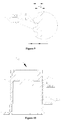
- Figure 10 is a schematic view showing the structure of the first housing according to the second embodiment, and the structure of the first housing according to the second embodiment will be described below.
- the first housing 2a includes a first heat dissipating portion 26a.
- An area of a projection of the first heat dissipating portion 26a onto an outer surface 212a of a corresponding side wall 21a is referred to as a first area
- a surface area of the first heat dissipating portion 26a is referred to as a second area
- the second area is larger than or equal to the first area.
- the defined surface K' is an outer surface not provided with the first heat dissipating portion 26a
- the first area is a surface area of the defined surface K'
- the outer surface 212' in Figure 7 is fitted to Figure 10 to obtain the defined surface K' (the dotted line in Figure 11 ).
- the first heat dissipating portion 26a includes multiple convex portions 262a, and the multiple convex portions 262a are arranged protruding away from the defined surface K'.
- the first heat dissipating portion 26a is directly provided on the bare outer surface in this embodiment instead of by means of peeling, thereby increasing a heat dissipating area of the first housing 2, which facilitates the heat dissipation of the stator assembly and the electric control board.
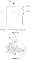
- Figure 11 is a schematic view showing the structure of the first housing according to the third embodiment, and the structure of the first housing according to the third embodiment will be described below.
- the first housing 2b includes a first heat dissipating portion 26b.
- the first heat dissipating portion 26b includes multiple convex portions 262b, and the convex portions 262b are arranged protruding away from an outer surface 212b.
- the multiple convex portions 262b are continuously arranged along an axial direction of the first housing 2b, where the term "continuously arranged" means that each two adjacent convex portions 212b are connected end to end.
- the convex portions 262b have the same convex height, and a corresponding wall thickness of the first housing 2 at a corresponding convex portion 262b is larger than or equal to 1.5 times the convex height of the corresponding convex portion 262b.
- the first heat dissipation 26b in this embodiment only includes the convex portions 262b, and does not include any concave portions, which also facilitates relatively increasing an area of the outer surface and thereby the heat dissipation area of the first heat dissipating portion 26b, thereby facilitating the heat dissipation of the stator assembly and the electric control board.
- Figure 12 is a schematic view showing the structure of the first housing according to the fourth embodiment, and the structure of the first housing according to the fourth embodiment will be described below.
- the first housing 2c includes a first heat dissipating portion 26c.
- the first heat dissipating portion 26c includes multiple concave portions 261c.
- the concave portions 261c are concaved from an outer surface 212c toward a central axis of the first housing 2c.
- the concave portions 261c are continuously arranged in an axial direction of the first housing 2c, where the term "continuously arranged" means that the each two adjacent concave portions 261c are connected end to end.
- a corresponding wall thickness of the first housing 2c at a corresponding concave portion 261c of the first heat dissipating portion 26c is larger than or equal to 0.5 times a concave depth of the corresponding concave portion 261c.
- the first heat dissipating portion 26c includes only the concave portions 261c, and does not include any convex portions, which also facilitates relatively increasing an area of the outer surface and thereby the heat dissipation area of the first heat dissipating portion, thereby facilitating the heat dissipation of the stator assembly and the electric control board.
- the electric oil pump further includes a second housing 7, and the second housing 7 is fixedly connected to the first housing 2.
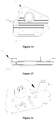
- Figures 13 to 15 are schematic views showing the structure of the second housing.
- the second housing includes multiple convex ribs 74, and the convex ribs 74 and the second housing 7 are fixedly connected to each other or formed as one piece.
- the convex ribs 74 are integrally formed with the second housing 7 by injection molding.
- the convex ribs 74 are arranged protruding away from the first housing 2, and the second housing 7 includes a plug 76.
- the plug 76 is arranged protruding away from the first housing 2.
- a region of the second housing 7 covered by the convex ribs is referred to as a first region, and an area of the first region is a third area.
- the electric control board 6 includes a substrate 61 and a heat-generating electric element 62, and the heat-generating electric element 62 is arranged on the substrate 61.
- a region of the substrate 61 covered by the heat-generating electric element 62 is referred to as a second region, and an area of the second region is a fourth area.
- the first region and the second regions are correspondingly arranged.
- At least a part of a vertical projection of the first region is overlapped with at least a part of a vertical projection of the second region and the third area is larger than or equal to the fourth area, by which it is sufficiently ensured that the heat generated by the heat-generating electric element 62 provided on the substrate 61 can be timely dissipated through the convex ribs in a short time, thereby reducing the influence of heat generated by the heat-generating electric element on the performance of the electric control board.
- the second housing 7 further includes a first side wall 75.
- the convex ribs 74 are arranged substantially parallel to the first side wall 75, where the term "substantially parallel” means a depth of parallelism of the convex ribs 74 is within 0.5mm with the first side wall 75 serving as a reference surface, such that it can be ensured that as many convex ribs 74 as possible can be provided on the second housing, thereby increasing the heat dissipation area and facilitating the heat dissipation of the circuit board.
- the convex ribs 74 can also be arranged at an angle with the first side wall 75.
- a shape of a transverse section of the convex rib 74 is a rectangle, while in practice, the transverse section of the convex rib may also have other shapes, such as a trapezoid, a triangle, and an arc.
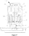
- FIG 17 is a schematic view showing the structure of an electric oil pump according to another embodiment.
- the electric oil pump 100' includes a pump housing, and the pump housing includes a pump cover 1, a first housing 2 and a second housing 7, where the pump cover 1, the first housing 2 and the second housing 7 are relatively fixedly connected.
- the pump housing defines a pump cavity, and the pump cavity includes a first cavity 80 and a second cavity 90, the first cavity 80 has a working medium flowing through, and a pump rotor assembly 8 and an electric control board 6 are provided in the first cavity 80; and the second cavity 90 has a working medium passing through, a stator assembly 4, a motor rotor assembly 3 and an electric control board 6 are provided in the second cavity 90.
- the electric oil pump 100' further includes a pump shaft 5', the pump shaft 5' includes a shaft hole 50 which connects the working media of the first cavity 80 and the second cavity 90 to each other, such that the working medium in the first cavity can flow into the second cavity through the shaft hole 50.
- the second cavity of the electric oil pump according to this embodiment has a working medium passing through, so that the working medium in the second cavity can also take away a part of heat generated by the stator assembly 4 during operation, which better facilitates heat dissipation of the stator assembly.
Landscapes
- Engineering & Computer Science (AREA)
- General Engineering & Computer Science (AREA)
- Mechanical Engineering (AREA)
- Physics & Mathematics (AREA)
- Thermal Sciences (AREA)
- Power Engineering (AREA)
- Details And Applications Of Rotary Liquid Pumps (AREA)
- Rotary Pumps (AREA)
Applications Claiming Priority (2)
| Application Number | Priority Date | Filing Date | Title |
|---|---|---|---|
| CN201710770143.4A CN109424540A (zh) | 2017-08-31 | 2017-08-31 | 电子油泵 |
| PCT/CN2018/090337 WO2019041953A1 (zh) | 2017-08-31 | 2018-06-08 | 电子油泵 |
Publications (2)
| Publication Number | Publication Date |
|---|---|
| EP3677778A1 true EP3677778A1 (de) | 2020-07-08 |
| EP3677778A4 EP3677778A4 (de) | 2020-12-23 |
Family
ID=65504631
Family Applications (1)
| Application Number | Title | Priority Date | Filing Date |
|---|---|---|---|
| EP18849856.2A Pending EP3677778A4 (de) | 2017-08-31 | 2018-06-08 | Elektrische ölpumpe |
Country Status (5)
| Country | Link |
|---|---|
| US (1) | US20200347838A1 (de) |
| EP (1) | EP3677778A4 (de) |
| JP (1) | JP7414711B2 (de) |
| CN (1) | CN109424540A (de) |
| WO (1) | WO2019041953A1 (de) |
Families Citing this family (5)
| Publication number | Priority date | Publication date | Assignee | Title |
|---|---|---|---|---|
| CN114659301B (zh) * | 2020-12-23 | 2024-09-10 | 法雷奥汽车空调湖北有限公司 | 一种电子膨胀阀 |
| CN115143098B (zh) * | 2021-03-30 | 2024-04-19 | 浙江三花汽车零部件有限公司 | 电子油泵 |
| KR102825791B1 (ko) * | 2021-10-21 | 2025-06-27 | 한온시스템 주식회사 | 전동 압축기 |
| CN114198630B (zh) * | 2021-11-12 | 2023-07-21 | 绵阳富临精工股份有限公司 | 一种电子油泵 |
| CN116448353B (zh) * | 2023-05-15 | 2025-06-27 | 华域皮尔博格泵技术有限公司 | 一种用于测试电子油泵气密性的工装及方法 |
Family Cites Families (21)
| Publication number | Priority date | Publication date | Assignee | Title |
|---|---|---|---|---|
| JP2002276571A (ja) | 2001-03-16 | 2002-09-25 | Tokico Ltd | スクロール式流体機械 |
| JP2005337095A (ja) | 2004-05-26 | 2005-12-08 | Aisin Seiki Co Ltd | 電動ポンプ |
| CN2821225Y (zh) * | 2005-08-17 | 2006-09-27 | 吴永祥 | 一种转子泵 |
| JP2008193858A (ja) | 2007-02-07 | 2008-08-21 | Mitsuba Corp | キャンドモータ |
| JP5418053B2 (ja) * | 2009-08-05 | 2014-02-19 | 株式会社ジェイテクト | トランスミッション用電動ポンプユニット |
| JP5372649B2 (ja) * | 2009-08-05 | 2013-12-18 | 日立オートモティブシステムズ株式会社 | 電動ポンプ |
| JP6108590B2 (ja) * | 2012-01-17 | 2017-04-05 | アスモ株式会社 | 電動ポンプ |
| JP6084858B2 (ja) * | 2013-02-25 | 2017-02-22 | アスモ株式会社 | 電動ポンプ及び電動ポンプの組付方法 |
| CN203348071U (zh) * | 2013-07-03 | 2013-12-18 | 自贡市川力实业有限公司 | 一种发动机冷却水摆线泵 |
| JP2015224600A (ja) | 2014-05-28 | 2015-12-14 | 株式会社豊田自動織機 | 電動過給機 |
| CZ201597A3 (cs) * | 2015-02-13 | 2016-02-24 | Jihostroj A.S. | Zubové čerpadlo s pohonem |
| JP6682769B2 (ja) | 2015-05-29 | 2020-04-15 | 日本電産トーソク株式会社 | ポンプ装置 |
| CN204696894U (zh) * | 2015-06-26 | 2015-10-07 | 奉化市兴宇特种电机制造有限公司 | 一种船用电笛驱动直流无刷电机 |
| JP2017013592A (ja) * | 2015-06-30 | 2017-01-19 | Ntn株式会社 | インホイールモータ駆動装置 |
| JP6502811B2 (ja) * | 2015-09-18 | 2019-04-17 | アイシン精機株式会社 | 電動ポンプ |
| CN106640673B (zh) * | 2015-10-30 | 2019-12-13 | 浙江三花汽车零部件有限公司 | 电驱动泵 |
| CN205714508U (zh) * | 2016-06-03 | 2016-11-23 | 温州市康松汽车零部件有限公司 | 一种电动燃油泵的转子机构 |
| CN207420851U (zh) * | 2017-08-31 | 2018-05-29 | 杭州三花研究院有限公司 | 油泵 |
| CN207761934U (zh) * | 2017-08-31 | 2018-08-24 | 杭州三花研究院有限公司 | 电子油泵 |
| CN207363873U (zh) * | 2017-08-31 | 2018-05-15 | 杭州三花研究院有限公司 | 电子油泵 |
| CN207363874U (zh) * | 2017-08-31 | 2018-05-15 | 杭州三花研究院有限公司 | 电子油泵 |
-
2017
- 2017-08-31 CN CN201710770143.4A patent/CN109424540A/zh active Pending
-
2018
- 2018-06-08 WO PCT/CN2018/090337 patent/WO2019041953A1/zh not_active Ceased
- 2018-06-08 EP EP18849856.2A patent/EP3677778A4/de active Pending
- 2018-06-08 JP JP2020512029A patent/JP7414711B2/ja active Active
- 2018-06-08 US US16/642,850 patent/US20200347838A1/en not_active Abandoned
Also Published As
| Publication number | Publication date |
|---|---|
| CN109424540A (zh) | 2019-03-05 |
| EP3677778A4 (de) | 2020-12-23 |
| JP7414711B2 (ja) | 2024-01-16 |
| WO2019041953A1 (zh) | 2019-03-07 |
| JP2021501281A (ja) | 2021-01-14 |
| US20200347838A1 (en) | 2020-11-05 |
Similar Documents
| Publication | Publication Date | Title |
|---|---|---|
| EP3677778A1 (de) | Elektrische ölpumpe | |
| US11976658B2 (en) | Electric pump with cooling channel arrangement | |
| EP3674562A1 (de) | Elektrische pumpe | |
| EP3677779B1 (de) | Elektrische ölpumpe | |
| EP3770434A1 (de) | Elektronische ölpumpe | |
| CN108286523B (zh) | 一种永磁电动机直接驱动的高速离心泵 | |
| EP3088738B1 (de) | Kreiselpumpe und verfahren zur herstellung davon | |
| CN211692949U (zh) | 轴流风叶及具有该风叶的风机 | |
| WO2018153350A1 (zh) | 叶轮以及电动泵 | |
| CN104410182A (zh) | 一种电泵 | |
| CN110131163B (zh) | 电动泵 | |
| CN104578546A (zh) | 第二代水冷式电动机 | |
| CN110821820B (zh) | 电子油泵 | |
| EP3677780A1 (de) | Ölpumpe | |
| CN207761934U (zh) | 电子油泵 | |
| CN209150874U (zh) | 一种电机壳体散热结构 | |
| CN106487143A (zh) | 新型电机前端盖 | |
| CN210201641U (zh) | 电机散热结构 | |
| CN108110925B (zh) | 一种永磁电动机 | |
| CN110821821B (zh) | 电子油泵 | |
| CN223843605U (zh) | 油冷电机定子结构和油冷电机 | |
| CN107514390A (zh) | 流体泵 | |
| CN206206265U (zh) | 叶轮和具有其的风机 | |
| CN210404945U (zh) | 一种高压电机水冷端盖 | |
| CN223648059U (zh) | 液体泵 |
Legal Events
| Date | Code | Title | Description |
|---|---|---|---|
| STAA | Information on the status of an ep patent application or granted ep patent |
Free format text: STATUS: THE INTERNATIONAL PUBLICATION HAS BEEN MADE |
|
| PUAI | Public reference made under article 153(3) epc to a published international application that has entered the european phase |
Free format text: ORIGINAL CODE: 0009012 |
|
| STAA | Information on the status of an ep patent application or granted ep patent |
Free format text: STATUS: REQUEST FOR EXAMINATION WAS MADE |
|
| 17P | Request for examination filed |
Effective date: 20200312 |
|
| AK | Designated contracting states |
Kind code of ref document: A1 Designated state(s): AL AT BE BG CH CY CZ DE DK EE ES FI FR GB GR HR HU IE IS IT LI LT LU LV MC MK MT NL NO PL PT RO RS SE SI SK SM TR |
|
| AX | Request for extension of the european patent |
Extension state: BA ME |
|
| DAV | Request for validation of the european patent (deleted) | ||
| DAX | Request for extension of the european patent (deleted) | ||
| A4 | Supplementary search report drawn up and despatched |
Effective date: 20201123 |
|
| RIC1 | Information provided on ipc code assigned before grant |
Ipc: F04C 2/10 20060101AFI20201117BHEP Ipc: H02K 5/18 20060101ALI20201117BHEP Ipc: F04C 2/08 20060101ALI20201117BHEP Ipc: F04C 15/00 20060101ALI20201117BHEP Ipc: F04C 29/04 20060101ALI20201117BHEP Ipc: F04D 25/08 20060101ALI20201117BHEP |
|
| RAP1 | Party data changed (applicant data changed or rights of an application transferred) |
Owner name: ZHEJIANG SANHUA INTELLIGENT CONTROLS CO., LTD. |
|
| STAA | Information on the status of an ep patent application or granted ep patent |
Free format text: STATUS: EXAMINATION IS IN PROGRESS |
|
| 17Q | First examination report despatched |
Effective date: 20230713 |