EP3677800A1 - Holzschraube - Google Patents
Holzschraube Download PDFInfo
- Publication number
- EP3677800A1 EP3677800A1 EP19216561.1A EP19216561A EP3677800A1 EP 3677800 A1 EP3677800 A1 EP 3677800A1 EP 19216561 A EP19216561 A EP 19216561A EP 3677800 A1 EP3677800 A1 EP 3677800A1
- Authority
- EP
- European Patent Office
- Prior art keywords
- thread
- locking thread
- tapered portion
- workpiece
- screw
- Prior art date
- Legal status (The legal status is an assumption and is not a legal conclusion. Google has not performed a legal analysis and makes no representation as to the accuracy of the status listed.)
- Withdrawn
Links
Images




Classifications
-
- F—MECHANICAL ENGINEERING; LIGHTING; HEATING; WEAPONS; BLASTING
- F16—ENGINEERING ELEMENTS AND UNITS; GENERAL MEASURES FOR PRODUCING AND MAINTAINING EFFECTIVE FUNCTIONING OF MACHINES OR INSTALLATIONS; THERMAL INSULATION IN GENERAL
- F16B—DEVICES FOR FASTENING OR SECURING CONSTRUCTIONAL ELEMENTS OR MACHINE PARTS TOGETHER, e.g. NAILS, BOLTS, CIRCLIPS, CLAMPS, CLIPS OR WEDGES; JOINTS OR JOINTING
- F16B25/00—Screws that cut thread in the body into which they are screwed, e.g. wood screws
- F16B25/001—Screws that cut thread in the body into which they are screwed, e.g. wood screws characterised by the material of the body into which the screw is screwed
- F16B25/0015—Screws that cut thread in the body into which they are screwed, e.g. wood screws characterised by the material of the body into which the screw is screwed the material being a soft organic material, e.g. wood or plastic
-
- F—MECHANICAL ENGINEERING; LIGHTING; HEATING; WEAPONS; BLASTING
- F16—ENGINEERING ELEMENTS AND UNITS; GENERAL MEASURES FOR PRODUCING AND MAINTAINING EFFECTIVE FUNCTIONING OF MACHINES OR INSTALLATIONS; THERMAL INSULATION IN GENERAL
- F16B—DEVICES FOR FASTENING OR SECURING CONSTRUCTIONAL ELEMENTS OR MACHINE PARTS TOGETHER, e.g. NAILS, BOLTS, CIRCLIPS, CLAMPS, CLIPS OR WEDGES; JOINTS OR JOINTING
- F16B25/00—Screws that cut thread in the body into which they are screwed, e.g. wood screws
- F16B25/0036—Screws that cut thread in the body into which they are screwed, e.g. wood screws characterised by geometric details of the screw
- F16B25/0042—Screws that cut thread in the body into which they are screwed, e.g. wood screws characterised by geometric details of the screw characterised by the geometry of the thread, the thread being a ridge wrapped around the shaft of the screw
- F16B25/0052—Screws that cut thread in the body into which they are screwed, e.g. wood screws characterised by geometric details of the screw characterised by the geometry of the thread, the thread being a ridge wrapped around the shaft of the screw the ridge having indentations, notches or the like in order to improve the cutting behaviour
-
- F—MECHANICAL ENGINEERING; LIGHTING; HEATING; WEAPONS; BLASTING
- F16—ENGINEERING ELEMENTS AND UNITS; GENERAL MEASURES FOR PRODUCING AND MAINTAINING EFFECTIVE FUNCTIONING OF MACHINES OR INSTALLATIONS; THERMAL INSULATION IN GENERAL
- F16B—DEVICES FOR FASTENING OR SECURING CONSTRUCTIONAL ELEMENTS OR MACHINE PARTS TOGETHER, e.g. NAILS, BOLTS, CIRCLIPS, CLAMPS, CLIPS OR WEDGES; JOINTS OR JOINTING
- F16B25/00—Screws that cut thread in the body into which they are screwed, e.g. wood screws
- F16B25/0036—Screws that cut thread in the body into which they are screwed, e.g. wood screws characterised by geometric details of the screw
- F16B25/0084—Screws that cut thread in the body into which they are screwed, e.g. wood screws characterised by geometric details of the screw characterised by geometric details of the tip
-
- F—MECHANICAL ENGINEERING; LIGHTING; HEATING; WEAPONS; BLASTING
- F16—ENGINEERING ELEMENTS AND UNITS; GENERAL MEASURES FOR PRODUCING AND MAINTAINING EFFECTIVE FUNCTIONING OF MACHINES OR INSTALLATIONS; THERMAL INSULATION IN GENERAL
- F16B—DEVICES FOR FASTENING OR SECURING CONSTRUCTIONAL ELEMENTS OR MACHINE PARTS TOGETHER, e.g. NAILS, BOLTS, CIRCLIPS, CLAMPS, CLIPS OR WEDGES; JOINTS OR JOINTING
- F16B25/00—Screws that cut thread in the body into which they are screwed, e.g. wood screws
- F16B25/10—Screws performing an additional function to thread-forming, e.g. drill screws or self-piercing screws
- F16B25/103—Screws performing an additional function to thread-forming, e.g. drill screws or self-piercing screws by means of a drilling screw-point, i.e. with a cutting and material removing action
Definitions
- the present invention relates to a wood screw, especially to a wood screw that is able to be driven into workpieces more smoothly and firmly.
- the respective screw revealed in these prior arts mainly includes a screw head and a screw shank connected to the screw head.
- a cone is formed on a rear end of the screw shank and the screw shank has the same diameter from one end with the cone to the other end connected to the head.
- a thread is running helically from the cone along the length direction of the screw shank.
- a plurality of drilling units is arranged at the screw shank along the length direction linearly or obliquely and each drilling unit would extend across/or not extend across one pitch of the thread.
- the screw includes a plurality of hole expanding blocks (with the reference number 221 in Fig. 2B ) linearly arranged at a screw shank having the same diameter.
- the respective hole expanding block doesn't span one pitch of a thread of the screw.
- a plurality of spiral cutting edges (with the reference number 331 in Fig. 1 ) is obliquely disposed on a rod (shank) having the same diameter of a screw.
- Each spiral cutting edge 331 extends across at least one pitch of a thread of the screw.
- a shaft of a screw is provided with a plurality of ribs (with the reference number 3 in Fig. 1 ) arranged linearly.
- the rib spans at least one pitch of a thread of the screw with the same diameter.
- Taiwanese Pat. Pub. No. 201544718A a wood screw is revealed.
- a cylindrical screw rod having the same diameter is provided with a plurality of elevations (with the reference number 4 in Fig.1 and Fig. 4 ) arranged linearly thereof.
- the elevation (4 in Fig. 1 ) extends across at least one pitch of a thread of the screw while another type of elevation (4 in Fig. 4 ) doesn't span one pitch of the thread of the screw.
- the drilling unit has an outside diameter larger than the core diameter of the thread in order to reduce driving torque.
- the inside diameter of the threaded hole formed in the workpiece by the drilling unit is greater than the core diameter of the thread.
- This results in various shortcomings such as poor engagement between the thread of the screw and the internal thread of the workpiece.
- the connection strength between the screw joined with the workpiece is reduced.
- all of the drilling units in the above prior arts are formed on the cylindrical shank with the same diameter. Thus the drilling units only destroy the workpiece material lying adjacent to the shank surface during the process the screw being threaded into the workpiece and a hole is generated around the periphery of the shank. Once the shank is inserted into the workpiece by the thread, the workpiece material is compressed to have a higher density.
- both the drilling units and the threads are formed on the shank with the same diameter.
- the resistance that the drilling units encounter during cutting of the workpiece is getting greater. The operator needs to put in more effort to complete the job.
- the screw available now is unable to be threaded into the workpiece smoothly.
- a wood screw according to the present invention mainly includes a head and a shank connected to the head.
- the shank is formed by a main shank portion and a tapered portion whose diameter is smaller than that of the main shank portion.
- Both the main shank portion and the tapered portion are provided with a locking thread.
- a plurality of drilling units is disposed on the tapered portion while an outside diameter of the drilling unit is smaller than that of the locking thread of the tapered portion.
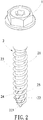
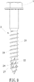
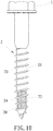
- a wood screw according to the present invention mainly includes a head 1 and a shank 2 integrally connected to the head 1.
- the shank 2 consists of a main shank portion 21 and a tapered portion 22. Both the main shank portion 21 and the tapered portion 22 have a first end and a second end opposite to each other.
- the first end of the main shank portion 21 is facing the head 1 and the second end of the main shank portion 21 is connected to the first end of the tapered portion 22 while a conical end 221 is formed on the second end of the tapered portion 22.
- the diameter of the tapered portion 22 (D1) is smaller than the diameter of the main shank portion 21 (D2). Also refer to Fig. 2 and Fig.
- a first locking thread 23 is formed on the main shank portion 21 and extending from the second end to the first end of the main shank portion 21.
- a second locking thread 24 is formed on the tapered portion 22, extending from the second end to the first end of the tapered portion 22 and connected to the first locking thread 23.
- the diameter of the tapered portion 22 (D1) is the core diameter of the second locking thread 24 while the diameter of the main shank portion 21 (D2) forms the core diameter of the first locking thread 23.
- a plurality of drilling units 25 is disposed on the tapered portion 22, obliquely to the length direction of the tapered portion 22, and spaced apart from one another.
- Each of the drilling units 25 spans at least one thread pitch (P) of the second locking thread 24 so that the top end and the bottom end of the drilling unit 25 are located in two different thread pitches of the second locking thread 24, respectively.
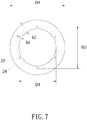
- the outside diameter (D3) of the drilling unit 25 is smaller than the outside diameter (D4) of the second locking thread 24 while the outside diameter (D4) of the second locking thread 24 is smaller than the outside diameter (D5) of the first locking thread 23.
- the height of the drilling unit 25 (h1) is no more than 0.9 times of the height (h2) of the second locking thread 24 (h2).
- the conical end 221 of the tapered portion 22 of the wood screw of the present invention is abutting against a workpiece while the wood screw is applied to workpieces such as wood, polywoods, etc. for screwing and fastening.
- the head 1 is driven by tools such as screwdrivers for rotating the tapered portion 22.
- the conical end 221 is driven into the workpiece and the drilling units 25 on the tapered portion 22 destroy the workpiece material radially.
- the volume of the main shank portion 21 being driven into the workpiece by the first locking thread 23 remains unchanged, the workpiece material has become loose with reduced density owing to the workpiece material has been destroyed in advance on the outer part of the main shank portion 21 in the relative position by the drilling units 25 on the tapered portion 22.
- the depth of the internal thread of the workpiece is getting larger along with the second locking thread 24 of the tapered portion 22 and the first locking thread 23 of the main shank portion 21 being screwed into the hole formed by the drilling units 25 in turn because that the outside diameter (D3) of the drilling unit 25 is smaller than the outside diameter (D4) of the second locking thread 24 and the outside diameter (D4) of the second locking thread 24 is smaller than the outside diameter (D5) of the first locking thread 23.
- an internal thread segment whose thread depth matches the thread depth of the first locking thread 23 of the main shank portion 21 for engagement is formed in the workpiece. Thereby the present wood screw and the workpiece are fastened and connected more firmly.
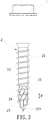
- a plurality of drilling units 26 is disposed on the tapered portion 22 linearly along the length direction of the tapered portion 22 and spaced from one another.
- Each of the drilling units 26 doesn't span one thread pitch (P) of the second locking thread 24 so that the top end and the bottom end of the drilling unit 26 are located in the same thread pitch of the second locking thread 24.
- a plurality of drilling units 27 is arranged obliquely to the length direction of the tapered portion 22 and spaced from one another.
- the respective drilling unit 27 doesn't extend across one thread pitch of the second locking thread 24 so that the top end and the bottom end of the drilling unit 27 are located in the same thread pitch of the second locking thread 24.
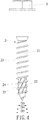
- a further embodiment is revealed.
- a plurality of drilling units 28 is formed on the tapered portion 22 linearly along the length direction of the tapered portion 22 and spaced from one another.
- the drilling unit 28 extends across at least one thread pitch of the second locking thread 24 so that the top end and the bottom end of the drilling unit 28 are located in two different thread pitches of the second locking thread 24, respectively.
- the above drilling units 26, 27, 28 can also destroy the workpiece material in advance for reducing the torque required to drive the first locking thread 23 of the main shank portion 21 into the workpiece. Thus the wood screw and the workpiece are fastened with each other more smoothly.
- the present invention has the following advantages according to the above embodiments:
Landscapes
- Engineering & Computer Science (AREA)
- General Engineering & Computer Science (AREA)
- Mechanical Engineering (AREA)
- Physics & Mathematics (AREA)
- Geometry (AREA)
- Life Sciences & Earth Sciences (AREA)
- Chemical & Material Sciences (AREA)
- Dispersion Chemistry (AREA)
- Wood Science & Technology (AREA)
- Connection Of Plates (AREA)
- Drilling Tools (AREA)
- Joining Of Building Structures In Genera (AREA)
Applications Claiming Priority (2)
| Application Number | Priority Date | Filing Date | Title |
|---|---|---|---|
| TW108100406A TWI745647B (zh) | 2019-01-04 | 2019-01-04 | 木螺絲結構 |
| US16/281,310 US11137012B2 (en) | 2019-02-21 | 2019-02-21 | Wood screw |
Publications (1)
| Publication Number | Publication Date |
|---|---|
| EP3677800A1 true EP3677800A1 (de) | 2020-07-08 |
Family
ID=68917626
Family Applications (1)
| Application Number | Title | Priority Date | Filing Date |
|---|---|---|---|
| EP19216561.1A Withdrawn EP3677800A1 (de) | 2019-01-04 | 2019-12-16 | Holzschraube |
Country Status (2)
| Country | Link |
|---|---|
| EP (1) | EP3677800A1 (de) |
| JP (1) | JP7016852B2 (de) |
Families Citing this family (1)
| Publication number | Priority date | Publication date | Assignee | Title |
|---|---|---|---|---|
| TWI768825B (zh) | 2021-04-13 | 2022-06-21 | 寬仕工業股份有限公司 | 螺絲 |
Citations (8)
| Publication number | Priority date | Publication date | Assignee | Title |
|---|---|---|---|---|
| US5827030A (en) * | 1995-09-06 | 1998-10-27 | A-Z Ausrustung Und Zubehor Gmbh & Co., Kg | Thread forming joining elements |
| EP1411252A2 (de) | 2002-08-29 | 2004-04-21 | Schmid Schrauben Hainfeld Gesellschaft m.b.H. | Schraube zur Verwendung bei aus Holz hergestellten Bauteilen |
| JP4531510B2 (ja) * | 2004-09-28 | 2010-08-25 | 誠一朗 高崎 | 木ねじ |
| US20130039720A1 (en) | 2011-08-11 | 2013-02-14 | Sheng-Tsai SHIH | Screw |
| TW201544718A (zh) | 2014-05-27 | 2015-12-01 | Avvio Gmbh & Co Kg | 螺絲 |
| US20170241463A1 (en) | 2016-02-22 | 2017-08-24 | Bi-Mirth Corp. | Hole expanding screw |
| EP3379092A1 (de) * | 2017-03-20 | 2018-09-26 | Fushang Co., Ltd. | Schraube mit schneidzähnen |
| EP3401557A1 (de) * | 2017-05-12 | 2018-11-14 | Profix AG | Holzschraube |
Family Cites Families (4)
| Publication number | Priority date | Publication date | Assignee | Title |
|---|---|---|---|---|
| JPS5639767Y2 (de) * | 1979-07-16 | 1981-09-17 | ||
| JP3217685B2 (ja) * | 1996-02-08 | 2001-10-09 | 有限会社ダンドリ製作所 | 木枠調整用木ねじ |
| JP4832163B2 (ja) | 2006-05-26 | 2011-12-07 | 日本パワーファスニング株式会社 | 石膏ボード締結用の自己穿孔ねじ |
| JP2010190269A (ja) | 2009-02-17 | 2010-09-02 | Pias Hanbai Kk | 硬質木材用タッピンねじ |
-
2019
- 2019-12-16 EP EP19216561.1A patent/EP3677800A1/de not_active Withdrawn
- 2019-12-17 JP JP2019227334A patent/JP7016852B2/ja active Active
Patent Citations (9)
| Publication number | Priority date | Publication date | Assignee | Title |
|---|---|---|---|---|
| US5827030A (en) * | 1995-09-06 | 1998-10-27 | A-Z Ausrustung Und Zubehor Gmbh & Co., Kg | Thread forming joining elements |
| EP1411252A2 (de) | 2002-08-29 | 2004-04-21 | Schmid Schrauben Hainfeld Gesellschaft m.b.H. | Schraube zur Verwendung bei aus Holz hergestellten Bauteilen |
| JP4531510B2 (ja) * | 2004-09-28 | 2010-08-25 | 誠一朗 高崎 | 木ねじ |
| US20130039720A1 (en) | 2011-08-11 | 2013-02-14 | Sheng-Tsai SHIH | Screw |
| TW201544718A (zh) | 2014-05-27 | 2015-12-01 | Avvio Gmbh & Co Kg | 螺絲 |
| TWI626383B (zh) * | 2014-05-27 | 2018-06-11 | 阿維奧公司 | 螺絲 |
| US20170241463A1 (en) | 2016-02-22 | 2017-08-24 | Bi-Mirth Corp. | Hole expanding screw |
| EP3379092A1 (de) * | 2017-03-20 | 2018-09-26 | Fushang Co., Ltd. | Schraube mit schneidzähnen |
| EP3401557A1 (de) * | 2017-05-12 | 2018-11-14 | Profix AG | Holzschraube |
Also Published As
| Publication number | Publication date |
|---|---|
| JP2020109321A (ja) | 2020-07-16 |
| JP7016852B2 (ja) | 2022-02-07 |
Similar Documents
| Publication | Publication Date | Title |
|---|---|---|
| US11137012B2 (en) | Wood screw | |
| AU2003204604B2 (en) | Self-drilling fastener | |
| EP3379092B1 (de) | Schraube mit schneidzähnen | |
| US5516248A (en) | Low torque wood screw | |
| US7682119B2 (en) | Screw for fastening wooden materials | |
| JP6259826B2 (ja) | ドリルパイロットと逆ねじれ領域を持つ留め具 | |
| EP3354912B1 (de) | Schraube | |
| US4878794A (en) | Collated screw fasteners | |
| US20070147973A1 (en) | Dual threaded screw for composite materials | |
| CN1846071A (zh) | 埋头螺钉 | |
| JP5301939B2 (ja) | 固定素子 | |
| JP2015520832A (ja) | 複数のねじ領域を持つ留め具 | |
| EP1409179B1 (de) | Selbstpolierende und selbstschneidende nietanordnung | |
| US10344789B2 (en) | Self-drilling drywall anchor and a method of securing an anchor in a drywall | |
| US20150316088A1 (en) | Screwcon | |
| CN102165202A (zh) | 螺钉 | |
| EP3330552A1 (de) | Struktur einer schraube | |
| US12055174B2 (en) | Wood screw | |
| EP3399200A1 (de) | Schraube für dünne eisenbleche | |
| US10954982B2 (en) | Construction nailing screw | |
| US20200256372A1 (en) | Concrete Screw | |
| CN108291568A (zh) | 螺纹成形的螺钉 | |
| US9016995B1 (en) | Self-countersinking fastener | |
| TWI683966B (zh) | 螺絲 | |
| JP7016852B2 (ja) | 木ねじ構造 |
Legal Events
| Date | Code | Title | Description |
|---|---|---|---|
| PUAI | Public reference made under article 153(3) epc to a published international application that has entered the european phase |
Free format text: ORIGINAL CODE: 0009012 |
|
| STAA | Information on the status of an ep patent application or granted ep patent |
Free format text: STATUS: THE APPLICATION HAS BEEN PUBLISHED |
|
| AK | Designated contracting states |
Kind code of ref document: A1 Designated state(s): AL AT BE BG CH CY CZ DE DK EE ES FI FR GB GR HR HU IE IS IT LI LT LU LV MC MK MT NL NO PL PT RO RS SE SI SK SM TR |
|
| AX | Request for extension of the european patent |
Extension state: BA ME |
|
| STAA | Information on the status of an ep patent application or granted ep patent |
Free format text: STATUS: REQUEST FOR EXAMINATION WAS MADE |
|
| 17P | Request for examination filed |
Effective date: 20210108 |
|
| RBV | Designated contracting states (corrected) |
Designated state(s): AL AT BE BG CH CY CZ DE DK EE ES FI FR GB GR HR HU IE IS IT LI LT LU LV MC MK MT NL NO PL PT RO RS SE SI SK SM TR |
|
| STAA | Information on the status of an ep patent application or granted ep patent |
Free format text: STATUS: EXAMINATION IS IN PROGRESS |
|
| 17Q | First examination report despatched |
Effective date: 20220511 |
|
| STAA | Information on the status of an ep patent application or granted ep patent |
Free format text: STATUS: THE APPLICATION IS DEEMED TO BE WITHDRAWN |
|
| 18D | Application deemed to be withdrawn |
Effective date: 20250701 |