EP3677816B1 - Joint hydrostatique articulé en porte-à-faux - Google Patents
Joint hydrostatique articulé en porte-à-faux Download PDFInfo
- Publication number
- EP3677816B1 EP3677816B1 EP19219629.3A EP19219629A EP3677816B1 EP 3677816 B1 EP3677816 B1 EP 3677816B1 EP 19219629 A EP19219629 A EP 19219629A EP 3677816 B1 EP3677816 B1 EP 3677816B1
- Authority
- EP
- European Patent Office
- Prior art keywords
- seal
- axially extending
- extending segment
- shoe
- component
- Prior art date
- Legal status (The legal status is an assumption and is not a legal conclusion. Google has not performed a legal analysis and makes no representation as to the accuracy of the status listed.)
- Active
Links
Images
Classifications
-
- F—MECHANICAL ENGINEERING; LIGHTING; HEATING; WEAPONS; BLASTING
- F16—ENGINEERING ELEMENTS AND UNITS; GENERAL MEASURES FOR PRODUCING AND MAINTAINING EFFECTIVE FUNCTIONING OF MACHINES OR INSTALLATIONS; THERMAL INSULATION IN GENERAL
- F16J—PISTONS; CYLINDERS; SEALINGS
- F16J15/00—Sealings
- F16J15/44—Free-space packings
- F16J15/441—Free-space packings with floating ring
-
- F—MECHANICAL ENGINEERING; LIGHTING; HEATING; WEAPONS; BLASTING
- F01—MACHINES OR ENGINES IN GENERAL; ENGINE PLANTS IN GENERAL; STEAM ENGINES
- F01D—NON-POSITIVE DISPLACEMENT MACHINES OR ENGINES, e.g. STEAM TURBINES
- F01D11/00—Preventing or minimising internal leakage of working-fluid, e.g. between stages
- F01D11/001—Preventing or minimising internal leakage of working-fluid, e.g. between stages for sealing space between stator blade and rotor
-
- F—MECHANICAL ENGINEERING; LIGHTING; HEATING; WEAPONS; BLASTING
- F01—MACHINES OR ENGINES IN GENERAL; ENGINE PLANTS IN GENERAL; STEAM ENGINES
- F01D—NON-POSITIVE DISPLACEMENT MACHINES OR ENGINES, e.g. STEAM TURBINES
- F01D11/00—Preventing or minimising internal leakage of working-fluid, e.g. between stages
- F01D11/003—Preventing or minimising internal leakage of working-fluid, e.g. between stages by packing rings; Mechanical seals
-
- F—MECHANICAL ENGINEERING; LIGHTING; HEATING; WEAPONS; BLASTING
- F01—MACHINES OR ENGINES IN GENERAL; ENGINE PLANTS IN GENERAL; STEAM ENGINES
- F01D—NON-POSITIVE DISPLACEMENT MACHINES OR ENGINES, e.g. STEAM TURBINES
- F01D11/00—Preventing or minimising internal leakage of working-fluid, e.g. between stages
- F01D11/02—Preventing or minimising internal leakage of working-fluid, e.g. between stages by non-contact sealings, e.g. of labyrinth type
- F01D11/025—Seal clearance control; Floating assembly; Adaptation means to differential thermal dilatations
Definitions
- Exemplary embodiments pertain to the art of gas turbine engines and, more particularly, to a hydrostatic seal, in particular an articulating cantilevered hydrostatic seal.
- Hydrostatic seals exhibit less leakage compared to traditional knife edge seals while exhibiting a longer life than brush seals.
- Some hydrostatic seals may be used between a stator and a rotor within a gas turbine engine.
- the hydrostatic seal is mounted to the stator to maintain a desired gap dimension between the hydrostatic seal and the rotor.
- the hydrostatic seal has the ability to 'track' the relative movement between the stator and the rotor throughout the engine operating profile when a pressure differential is developed across the seal.
- Hydrostatic seals involve motion of a spring-attached shoe whose response is based on aerodynamic forces developed between the seal shoe and a rotor surface during operation. When properly designed, the hydrostatic seal will maintain tight clearances across the operating range of the engine. At operating conditions with high pressure differentials across the seal, though, the hydrostatic seal may have an inherent issue with friction that could result in the seal "locking-up” and not moving in response to aerodynamic loads on the seal. The immobilized seal could experience accelerated wear and excessive heat generation during maneuver operations where the rotor surface is moving relative to the static hydrostatic seal.
- US 4998739 teaches an arrangement for the sealing-off of spaces acted upon by media of a different pressure for turbomachines, comprising a sealing ring centered by means of spring elements.
- WO 2014/022290 teaches a seal assembly including multiple sealing device segments, each including a shoe plate with a forward-shoe section and an aft-shoe section.
- EP 2580498 B1 discloses a seal assembly for use between a rotating component and a stationary component in a turbo machine, the seal assembly comprising a leaf seal assembly.
- a hydrostatic seal configured to be disposed between relatively rotatable components, the seal comprising: a seal housing; and a shoe having a first axially extending segment; wherein the shoe has a second axially extending segment, and a radially extending segment joining the first and second axially extending segments, the shoe cantilevered to the seal housing at a forward end or an aft end of the first axially extending segment; characterised in that: the first and second axially extending segments deflect during operation of the seal and the radially extending segment bends during operation of the seal.
- the first axially extending segment may be located radially outward of the second axially extending segment, wherein the first axially extending segment may be cantilevered to the seal housing.
- the first axially extending segment may be cantilevered to the seal housing at the forward end of the first axially extending segment.
- a forward end of the second axially extending segment may be a free end.
- the shoe may be a C-shaped structure.
- the first axially extending segment may be cantilevered to the seal housing at the aft end of the first axially extending segment.
- an aft end of the second axially extending segment may be a free end.
- the shoe may include at least one tooth projecting radially away from a sealing surface of the shoe.
- the seal assembly disposed in a gas turbine engine.
- the seal assembly includes a first component.
- the seal assembly also includes a second component, the first component and the second component are relatively rotatable components.
- the seal assembly further includes a first hydrostatic seal according to any aspect or embodiment described above, disposed between the first component and the second component.
- the shoe is a C-shaped shoe
- the first axially extending segment may be located radially outward of the second axially extending segment, wherein the first axially extending segment may be cantilevered to the seal housing.
- the first axially extending segment may be cantilevered to the seal housing at a forward end of the first axially extending segment.
- a forward end of the second axially extending segment may be a free end.
- first and second axially extending segments may deflect during operation of the seal and the radially extending segment may bend during operation of the seal.
- the first axially extending segment may be cantilevered to the seal housing at an aft end of the first axially extending segment.
- an aft end of the second axially extending segment may be a free end.
- the shoe may include at least one tooth projecting radially away from a sealing surface of the shoe.
- the first component may be a stator and the second component may be a rotor, wherein the seal may be operatively coupled to the stator.
- first component may be a stator and the second component may be a rotor, wherein the seal may be operatively coupled to the rotor.
- a gas turbine engine including a compressor section, a combustor section, a turbine section, and a seal assembly disposed in the gas turbine engine, the seal assembly comprising a stator, a rotor, and a first hydrostatic seal according to any aspect or embodiment described above, disposed between a stator and the rotor.
- the shoe is a C-shaped shoe.
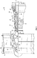
- FIG. 1 schematically illustrates a gas turbine engine 20.
- the gas turbine engine 20 is disclosed herein as a two-spool turbofan that generally incorporates a fan section 22, a compressor section 24, a combustor section 26 and a turbine section 28.
- the fan section 22 drives air along a bypass flow path B in a bypass duct, while the compressor section 24 drives air along a core flow path C for compression and communication into the combustor section 26 then expansion through the turbine section 28.
- FIG. 1 schematically illustrates a gas turbine engine 20.
- the gas turbine engine 20 is disclosed herein as a two-spool turbofan that generally incorporates a fan section 22, a compressor section 24, a combustor section 26 and a turbine section 28.
- the fan section 22 drives air along a bypass flow path B in a bypass duct
- the compressor section 24 drives air along a core flow path C for compression and communication into the combustor section 26 then expansion through the turbine section 28.
- the exemplary engine 20 generally includes a low speed spool 30 and a high speed spool 32 mounted for rotation about an engine central longitudinal axis A relative to an engine static structure 36 via several bearing systems 38. It should be understood that various bearing systems 38 at various locations may alternatively or additionally be provided, and the location of bearing systems 38 may be varied as appropriate to the application.
- the low speed spool 30 generally includes an inner shaft 40 that interconnects a fan 42, a low pressure compressor 44 and a low pressure turbine 46.
- the inner shaft 40 is connected to the fan 42 through a speed change mechanism, which in exemplary gas turbine engine 20 is illustrated as a geared architecture 48 to drive the fan 42 at a lower speed than the low speed spool 30.
- the high speed spool 32 includes an outer shaft 50 that interconnects a high pressure compressor 52 and high pressure turbine 54.
- a combustor 56 is arranged in exemplary gas turbine 20 between the high pressure compressor 52 and the high pressure turbine 54.
- An engine static structure 36 is arranged generally between the high pressure turbine 54 and the low pressure turbine 46.
- the engine static structure 36 further supports bearing systems 38 in the turbine section 28.
- the inner shaft 40 and the outer shaft 50 are concentric and rotate via bearing systems 38 about the engine central longitudinal axis A which is collinear with their longitudinal axes.
- each of the positions of the fan section 22, compressor section 24, combustor section 26, turbine section 28, and fan drive gear system 48 may be varied.
- gear system 48 may be located aft of combustor section 26 or even aft of turbine section 28, and fan section 22 may be positioned forward or aft of the location of gear system 48.
- the engine 20 in one example is a high-bypass geared aircraft engine.
- the engine 20 bypass ratio is greater than about six (6), with an example embodiment being greater than about ten (10)
- the geared architecture 48 is an epicyclic gear train, such as a planetary gear system or other gear system, with a gear reduction ratio of greater than about 2.3 and the low pressure turbine 46 has a pressure ratio that is greater than about five.
- the engine 20 bypass ratio is greater than about ten (10:1)
- the fan diameter is significantly larger than that of the low pressure compressor 44
- the low pressure turbine 46 has a pressure ratio that is greater than about five (5:1).
- Low pressure turbine 46 pressure ratio is pressure measured prior to inlet of low pressure turbine 46 as related to the pressure at the outlet of the low pressure turbine 46 prior to an exhaust nozzle.
- the geared architecture 48 may be an epicyclic gear train, such as a planetary gear system or other gear system, with a gear reduction ratio of greater than about 2.3:1. It should be understood, however, that the above parameters are only exemplary of one embodiment of a geared architecture engine and that the present disclosure is applicable to other gas turbine engines including direct drive turbofans.
- the fan section 22 of the engine 20 is designed for a particular flight condition--typically cruise at about 0.8 Mach and about 35,000 feet (10,668 meters).
- 'TSFC Thrust Specific Fuel Consumption
- Low fan pressure ratio is the pressure ratio across the fan blade alone, without a Fan Exit Guide Vane (“FEGV”) system.
- the low fan pressure ratio as disclosed herein according to one non-limiting embodiment is less than about 1.45.
- Low corrected fan tip speed is the actual fan tip speed in ft/sec divided by an industry standard temperature correction of [(Tram °R)/(518.7 °R)] 0.5 .
- the "Low corrected fan tip speed” as disclosed herein according to one non-limiting embodiment is less than about 1150 ft/second (350.5 m/sec).
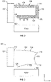
- FIGS. 2 and 3 illustrate a hydrostatic seal assembly indicated generally at 100.
- the hydrostatic seal assembly 100 (which can also be termed a hydrostatic seal 100) is intended to create a seal between two relatively rotating components, such as a fixed stator and a rotating rotor 102.
- the hydrostatic seal assembly 100 includes a housing 107 and an articulating seal 108, which is located in a non-contact position along the exterior surface of the rotor 102.
- the seal 108 is a substantially U-shaped structure in the illustrated embodiment, but it is to be appreciated that the seal 108 may have other geometries in alternative embodiments. It will also be appreciated that seal 108 may be referred to using other terminology, for example it may be referred to as shoe 108. In the following description the term “seal 108" is used, but this can therefore be alternatively understood as "shoe 108". These terms are intended to be interchangeable and have the same meaning.
- axial or "axially spaced” refers to a direction along the rotational axis of the rotor, whereas “radial” refers to a direction perpendicular to the rotational axis of the rotor.
- radial refers to a direction perpendicular to the rotational axis of the rotor.
- the Figures illustrate axial direction x, radial direction r.
- the embodiments described herein include a cantilevered seal. Therefore, the seal 108 is connected to the housing 107 of the seal assembly 100 in a pinned manner or some suitable alternative mechanical fastener that allows pivoting movement of the seal 108, relative to the housing 107.
- the housing 107 is fixed to a static structure.
- the seal 108 includes a first segment 109 extending axially rearward from a first end region 112 to a second end region 114, a second segment 116 extending radially inwardly from the second end region 114 to a third end region 118, and a third segment 120 extending axially forward from the third end region 118 to a fourth end region 122.
- the seal 108 is pinned (i.e., cantilevered) to the housing 107 at the first end region 112 of the first segment 109 of the seal, while the fourth end region 122 of the third segment 120 is free and not by design in contact with any other structure.
- the front end of the seal 108 is coupled to a radially extending portion of the housing 107, however, it is contemplated that the U- or C-shaped seal 108 is reversed in other embodiments, such that the seal 108 is cantilevered at an aft end to a portion of the housing 107 that is located aft of the seal 108.
- the seal 108 is an articulating seal that deflects along each of the three segments 109, 116, 120.
- the seal 108 is shown in a first condition in FIG. 2 , with no deflection of the seal present, while FIG.
- FIG 3 depicts a deflection profile of the seal 108 in a second condition.
- the first segment 109 i.e., top portion
- the third segment 120 i.e., bottom portion
- Such configurations provide an articulating seal that is stiffer and can thus be made axially shorter, when compared to other seal designs, including other cantilevered seals.
- the embodiments of the hydrostatic seal 100 described herein are frictionless and are more robust to wear, when compared to prior hydrostatic seals that have contact between stationary and moving components that, due to friction, can cause the shoe to become fully or partially pinned in place and be unable to avoid contact with the rotor during a transient maneuver.
- the seal 100 described herein is designed to eliminate rotor contact. Frictional loads are difficult to characterize and can change over the life of the seal and lead to flutter. The embodiments described herein avoid such problems.
Landscapes
- Engineering & Computer Science (AREA)
- General Engineering & Computer Science (AREA)
- Mechanical Engineering (AREA)
- Turbine Rotor Nozzle Sealing (AREA)
- Sealing Devices (AREA)
Claims (12)
- Joint hydrostatique (100) configuré pour être disposé entre des composants relativement rotatifs, le joint comprenant :un boîtier de joint (107) ; etun patin (108) ayant un premier segment s'étendant axialement (109) ;dans lequel le patin a un second segment s'étendant axialement (120) et un segment s'étendant radialement (116) joignant les premier et second segments s'étendant axialement, le patin étant en porte-à-faux par rapport au boîtier de joint à une extrémité avant (112) ou à une extrémité arrière (114) du premier segment s'étendant axialement ; caractérisé en ce que :
les premier et second segments s'étendant axialement (109, 120) fléchissent pendant le fonctionnement du joint et le segment s'étendant radialement (116) se plie pendant le fonctionnement du joint. - Joint selon la revendication 1, dans lequel le premier segment s'étendant axialement (109) est situé radialement vers l'extérieur du second segment s'étendant axialement (120), le premier segment s'étendant axialement étant en porte-à-faux par rapport au boîtier de joint (107).
- Joint selon la revendication 2, dans lequel le premier segment s'étendant axialement (109) est en porte-à-faux par rapport au boîtier de joint (107) à l'extrémité avant (112) du premier segment s'étendant axialement.
- Joint selon la revendication 2 ou 3, dans lequel une extrémité avant (122) du second segment s'étendant axialement (120) est une extrémité libre.
- Joint selon la revendication 2, dans lequel le premier segment s'étendant axialement (109) est en porte-à-faux par rapport au boîtier de joint (107) à l'extrémité avant (114) du premier segment s'étendant axialement.
- Joint selon la revendication 5, dans lequel une extrémité arrière du second segment s'étendant axialement (120) est une extrémité libre.
- Joint selon une quelconque revendication précédente, dans lequel le patin (108) comporte au moins une dent faisant saillie radialement à l'opposé d'une surface d'étanchéité du patin.
- Joint selon une quelconque revendication précédente, dans lequel le patin (108) est une structure en forme de C.
- Ensemble de joint disposé dans un moteur à turbine à gaz (20), l'ensemble de joint comprenant :un premier composant ;un second composant, dans lequel le premier composant et le second composant sont des composants relativement rotatifs ; etun premier joint hydrostatique (100) selon une quelconque revendication précédente disposé entre le premier composant et le second composant, dans lequel le patin (108) est en forme de C.
- Ensemble de joint selon la revendication 9, dans lequel le premier composant est un stator et le second composant est un rotor (102), le joint (100) étant fonctionnellement couplé au stator.
- Ensemble de joint selon la revendication 9, dans lequel le premier composant est un stator et le second composant est un rotor (102), le joint (100) étant fonctionnellement couplé au rotor.
- Moteur à turbine à gaz (20) comprenant :une section de compresseur (24) ;une section de chambre de combustion (26) ;une section de turbine (28) ; etun ensemble de joint disposé dans le moteur à turbine à gaz, l'ensemble de joint comprenant un stator, un rotor (102) et un premier joint hydrostatique (100) selon l'une quelconque des revendications 1 à 8 disposé entre le stator et le rotor, dans lequel le patin (108) est en forme de C.
Applications Claiming Priority (1)
| Application Number | Priority Date | Filing Date | Title |
|---|---|---|---|
| US16/239,231 US11378187B2 (en) | 2019-01-03 | 2019-01-03 | Articulating cantilevered hydrostatic seal |
Publications (2)
| Publication Number | Publication Date |
|---|---|
| EP3677816A1 EP3677816A1 (fr) | 2020-07-08 |
| EP3677816B1 true EP3677816B1 (fr) | 2022-10-05 |
Family
ID=69024182
Family Applications (1)
| Application Number | Title | Priority Date | Filing Date |
|---|---|---|---|
| EP19219629.3A Active EP3677816B1 (fr) | 2019-01-03 | 2019-12-24 | Joint hydrostatique articulé en porte-à-faux |
Country Status (2)
| Country | Link |
|---|---|
| US (1) | US11378187B2 (fr) |
| EP (1) | EP3677816B1 (fr) |
Families Citing this family (5)
| Publication number | Priority date | Publication date | Assignee | Title |
|---|---|---|---|---|
| US10995861B2 (en) | 2019-01-03 | 2021-05-04 | Raytheon Technologies Corporation | Cantilevered hydrostatic advanced low leakage seal |
| US10982770B2 (en) | 2019-01-03 | 2021-04-20 | Raytheon Technologies Corporation | Hydrostatic seal with extended housing |
| US10961858B2 (en) | 2019-01-04 | 2021-03-30 | Raytheon Technologies Corporation | Hydrostatic seal with enhanced maneuver response |
| US10975713B2 (en) | 2019-01-04 | 2021-04-13 | Raytheon Technologies Corporation | Hydrostatic seal with aft tooth |
| US12503950B2 (en) * | 2024-05-03 | 2025-12-23 | Rtx Corporation | Non-contact seal shoe with diffuser structure |
Citations (1)
| Publication number | Priority date | Publication date | Assignee | Title |
|---|---|---|---|---|
| EP3290756A1 (fr) * | 2016-09-01 | 2018-03-07 | United Technologies Corporation | Lèvre verticale de joint d'étanchéité sans contact flottant |
Family Cites Families (44)
| Publication number | Priority date | Publication date | Assignee | Title |
|---|---|---|---|---|
| US1187212A (en) * | 1913-08-20 | 1916-06-13 | Westinghouse Machine Co | Gland-packing. |
| GB1224234A (en) * | 1968-07-19 | 1971-03-03 | English Electric Co Ltd | Turbines |
| SE405406B (sv) * | 1972-12-05 | 1978-12-04 | Polysius Ag | Avtaetningsanordning foer en baerbaneaxel vid en vandringsrost |
| CH582319A5 (fr) * | 1975-03-05 | 1976-11-30 | Bbc Brown Boveri & Cie | |
| DE2743825C2 (de) * | 1977-09-29 | 1986-01-30 | SKF GmbH, 8720 Schweinfurt | Rollenmeißel |
| US4428587A (en) * | 1983-05-10 | 1984-01-31 | Firma Carl Freudenberg | Seal ring with channel for radially accelerating medium to be sealed |
| DE3828833A1 (de) | 1988-08-25 | 1990-03-01 | Mtu Muenchen Gmbh | Einrichtung zur abdichtung von durch medien, wie fluessigkeiten und/oder gasen, unterschiedlichen druckes beaufschlagten raeumen, insbesondere fuer turbomaschinen |
| US5626347A (en) * | 1994-09-29 | 1997-05-06 | Alliedsignal Inc. | Coning resistant face seal having a "U" shape |
| FR2782122B1 (fr) | 1998-08-05 | 2000-09-15 | Snecma | Agencement d'etancheite a reglage automatique de jeu |
| US6250640B1 (en) | 1998-08-17 | 2001-06-26 | General Electric Co. | Brush seals for steam turbine applications |
| EP1169586B1 (fr) | 2000-01-31 | 2007-02-21 | General Electric Company | Joints en brosses pour turbine a vapeur |
| US6715766B2 (en) * | 2001-10-30 | 2004-04-06 | General Electric Company | Steam feed hole for retractable packing segments in rotary machines |
| US6669443B2 (en) | 2001-11-16 | 2003-12-30 | General Electric Company | Rotor platform modification and methods using brush seals in diaphragm packing area of steam turbines to eliminate rotor bowing |
| US8641045B2 (en) * | 2003-05-01 | 2014-02-04 | Advanced Technologies Group, Inc. | Seal with stacked sealing elements |
| US8002285B2 (en) * | 2003-05-01 | 2011-08-23 | Justak John F | Non-contact seal for a gas turbine engine |
| US7896352B2 (en) * | 2003-05-01 | 2011-03-01 | Justak John F | Seal with stacked sealing elements |
| US8172232B2 (en) | 2003-05-01 | 2012-05-08 | Advanced Technologies Group, Inc. | Non-contact seal for a gas turbine engine |
| US7410173B2 (en) * | 2003-05-01 | 2008-08-12 | Justak John F | Hydrodynamic brush seal |
| US8919781B2 (en) | 2003-05-01 | 2014-12-30 | Advanced Technologies Group, Inc. | Self-adjusting non-contact seal |
| US20050200080A1 (en) * | 2004-03-10 | 2005-09-15 | Siemens Westinghouse Power Corporation | Seal for a turbine engine |
| US7735833B2 (en) | 2006-11-14 | 2010-06-15 | The University Of Akron | Double padded finger seal |
| US8905408B2 (en) * | 2008-05-22 | 2014-12-09 | Stein Seal Company | Windback device for a circumferential seal |
| US8474827B2 (en) | 2010-06-11 | 2013-07-02 | Cmg Tech, Llc | Film riding pressure actuated leaf seal assembly |
| US8600707B1 (en) | 2011-03-24 | 2013-12-03 | Florida Turbine Technologies, Inc. | Process for analyzing a labyrinth seal for flutter |
| US9255642B2 (en) * | 2012-07-06 | 2016-02-09 | General Electric Company | Aerodynamic seals for rotary machine |
| US9587746B2 (en) | 2012-07-31 | 2017-03-07 | General Electric Company | Film riding seals for rotary machines |
| US9045994B2 (en) | 2012-10-31 | 2015-06-02 | General Electric Company | Film riding aerodynamic seals for rotary machines |
| US9115810B2 (en) | 2012-10-31 | 2015-08-25 | General Electric Company | Pressure actuated film riding seals for turbo machinery |
| US9587505B2 (en) * | 2013-12-05 | 2017-03-07 | General Electric Company | L brush seal for turbomachinery application |
| WO2015147967A1 (fr) | 2014-03-27 | 2015-10-01 | United Technologies Corporation | Moteur à turbine à gaz et ensemble d'étanchéité associé |
| US9359908B2 (en) * | 2014-07-08 | 2016-06-07 | General Electric Company | Film riding seal assembly for turbomachinery |
| US9963991B2 (en) | 2014-10-01 | 2018-05-08 | United Technologies Corporation | Brush seal plate |
| US10801348B2 (en) | 2014-10-14 | 2020-10-13 | Raytheon Technologies Corporation | Non-contacting dynamic seal |
| US9988921B2 (en) | 2014-10-17 | 2018-06-05 | United Technologies Corporation | Circumferential seal with seal dampening elements |
| US20160109025A1 (en) | 2014-10-21 | 2016-04-21 | United Technologies Corporation | Seal ring |
| EP3034801B1 (fr) | 2014-10-23 | 2025-10-15 | RTX Corporation | Structure de support de joint d'étanchéité |
| US10094232B2 (en) | 2015-08-13 | 2018-10-09 | United Technologies Corporation | Self crystalline orientation for increased compliance |
| US10030531B2 (en) * | 2016-01-22 | 2018-07-24 | United Technologies Corporation | Seal shoe for a hydrostatic non-contact seal device |
| US10060535B2 (en) | 2016-02-25 | 2018-08-28 | United Technologies Corporation | Shaped spring element for a non-contact seal device |
| US20170306780A1 (en) * | 2016-04-25 | 2017-10-26 | United Technologies Corporation | Floating, non-contact seal with rounded edge |
| US10995861B2 (en) | 2019-01-03 | 2021-05-04 | Raytheon Technologies Corporation | Cantilevered hydrostatic advanced low leakage seal |
| US10982770B2 (en) | 2019-01-03 | 2021-04-20 | Raytheon Technologies Corporation | Hydrostatic seal with extended housing |
| US10961858B2 (en) | 2019-01-04 | 2021-03-30 | Raytheon Technologies Corporation | Hydrostatic seal with enhanced maneuver response |
| US10975713B2 (en) | 2019-01-04 | 2021-04-13 | Raytheon Technologies Corporation | Hydrostatic seal with aft tooth |
-
2019
- 2019-01-03 US US16/239,231 patent/US11378187B2/en active Active
- 2019-12-24 EP EP19219629.3A patent/EP3677816B1/fr active Active
Patent Citations (1)
| Publication number | Priority date | Publication date | Assignee | Title |
|---|---|---|---|---|
| EP3290756A1 (fr) * | 2016-09-01 | 2018-03-07 | United Technologies Corporation | Lèvre verticale de joint d'étanchéité sans contact flottant |
Also Published As
| Publication number | Publication date |
|---|---|
| EP3677816A1 (fr) | 2020-07-08 |
| US20200217421A1 (en) | 2020-07-09 |
| US11378187B2 (en) | 2022-07-05 |
Similar Documents
| Publication | Publication Date | Title |
|---|---|---|
| EP3677818B1 (fr) | Joint hydrostatique avancé en porte-à-faux à faible fuite | |
| US11519285B2 (en) | Bellows secondary seal for cantilevered hydrostatic advanced low leakage seal | |
| EP3677816B1 (fr) | Joint hydrostatique articulé en porte-à-faux | |
| EP3677817B1 (fr) | Joint hydrostatique à boîtier étendu | |
| EP3680520B1 (fr) | Joint hydrostatique affichant une meilleure réponse de man uvre | |
| US11047249B2 (en) | Labyrinth seal with passive check valve | |
| EP3680521B1 (fr) | Joint hydrostatique à dent arrière | |
| EP3789588B1 (fr) | Joint hydrostatique aligné avec la rotation du rotor | |
| EP3722560B1 (fr) | Joint hydrostatique avec protection de structure de joint secondaire | |
| EP3789589B1 (fr) | Joint hydrostatique | |
| EP3786418A1 (fr) | Joint hydrostatique doté de butées de joint d'étanchéité | |
| EP3660274A1 (fr) | Joint hydrostatique doté d'un espace de conception accru | |
| EP3739241B1 (fr) | Joint secondaire en brosses pour joint hydrostatique avancé en porte-à-faux à faible fuite | |
| EP3660363B1 (fr) | Joint hydrostatique à faisceaux non parallèles anti-basculement | |
| EP3660362A1 (fr) | Joint hydrostatique à faisceaux asymétriques pour anti-basculement | |
| US11629645B2 (en) | Hydrostatic seal with extended carrier arm |
Legal Events
| Date | Code | Title | Description |
|---|---|---|---|
| PUAI | Public reference made under article 153(3) epc to a published international application that has entered the european phase |
Free format text: ORIGINAL CODE: 0009012 |
|
| STAA | Information on the status of an ep patent application or granted ep patent |
Free format text: STATUS: THE APPLICATION HAS BEEN PUBLISHED |
|
| AK | Designated contracting states |
Kind code of ref document: A1 Designated state(s): AL AT BE BG CH CY CZ DE DK EE ES FI FR GB GR HR HU IE IS IT LI LT LU LV MC MK MT NL NO PL PT RO RS SE SI SK SM TR |
|
| AX | Request for extension of the european patent |
Extension state: BA ME |
|
| STAA | Information on the status of an ep patent application or granted ep patent |
Free format text: STATUS: REQUEST FOR EXAMINATION WAS MADE |
|
| 17P | Request for examination filed |
Effective date: 20210111 |
|
| RBV | Designated contracting states (corrected) |
Designated state(s): AL AT BE BG CH CY CZ DE DK EE ES FI FR GB GR HR HU IE IS IT LI LT LU LV MC MK MT NL NO PL PT RO RS SE SI SK SM TR |
|
| RAP1 | Party data changed (applicant data changed or rights of an application transferred) |
Owner name: RAYTHEON TECHNOLOGIES CORPORATION |
|
| STAA | Information on the status of an ep patent application or granted ep patent |
Free format text: STATUS: EXAMINATION IS IN PROGRESS |
|
| 17Q | First examination report despatched |
Effective date: 20210420 |
|
| GRAP | Despatch of communication of intention to grant a patent |
Free format text: ORIGINAL CODE: EPIDOSNIGR1 |
|
| STAA | Information on the status of an ep patent application or granted ep patent |
Free format text: STATUS: GRANT OF PATENT IS INTENDED |
|
| INTG | Intention to grant announced |
Effective date: 20220419 |
|
| GRAS | Grant fee paid |
Free format text: ORIGINAL CODE: EPIDOSNIGR3 |
|
| GRAA | (expected) grant |
Free format text: ORIGINAL CODE: 0009210 |
|
| STAA | Information on the status of an ep patent application or granted ep patent |
Free format text: STATUS: THE PATENT HAS BEEN GRANTED |
|
| AK | Designated contracting states |
Kind code of ref document: B1 Designated state(s): AL AT BE BG CH CY CZ DE DK EE ES FI FR GB GR HR HU IE IS IT LI LT LU LV MC MK MT NL NO PL PT RO RS SE SI SK SM TR |
|
| REG | Reference to a national code |
Ref country code: GB Ref legal event code: FG4D |
|
| REG | Reference to a national code |
Ref country code: CH Ref legal event code: EP |
|
| REG | Reference to a national code |
Ref country code: AT Ref legal event code: REF Ref document number: 1522930 Country of ref document: AT Kind code of ref document: T Effective date: 20221015 |
|
| REG | Reference to a national code |
Ref country code: DE Ref legal event code: R096 Ref document number: 602019020251 Country of ref document: DE |
|
| REG | Reference to a national code |
Ref country code: IE Ref legal event code: FG4D |
|
| REG | Reference to a national code |
Ref country code: LT Ref legal event code: MG9D |
|
| REG | Reference to a national code |
Ref country code: NL Ref legal event code: MP Effective date: 20221005 |
|
| REG | Reference to a national code |
Ref country code: AT Ref legal event code: MK05 Ref document number: 1522930 Country of ref document: AT Kind code of ref document: T Effective date: 20221005 |
|
| PG25 | Lapsed in a contracting state [announced via postgrant information from national office to epo] |
Ref country code: NL Free format text: LAPSE BECAUSE OF FAILURE TO SUBMIT A TRANSLATION OF THE DESCRIPTION OR TO PAY THE FEE WITHIN THE PRESCRIBED TIME-LIMIT Effective date: 20221005 |
|
| PG25 | Lapsed in a contracting state [announced via postgrant information from national office to epo] |
Ref country code: SE Free format text: LAPSE BECAUSE OF FAILURE TO SUBMIT A TRANSLATION OF THE DESCRIPTION OR TO PAY THE FEE WITHIN THE PRESCRIBED TIME-LIMIT Effective date: 20221005 Ref country code: PT Free format text: LAPSE BECAUSE OF FAILURE TO SUBMIT A TRANSLATION OF THE DESCRIPTION OR TO PAY THE FEE WITHIN THE PRESCRIBED TIME-LIMIT Effective date: 20230206 Ref country code: NO Free format text: LAPSE BECAUSE OF FAILURE TO SUBMIT A TRANSLATION OF THE DESCRIPTION OR TO PAY THE FEE WITHIN THE PRESCRIBED TIME-LIMIT Effective date: 20230105 Ref country code: LT Free format text: LAPSE BECAUSE OF FAILURE TO SUBMIT A TRANSLATION OF THE DESCRIPTION OR TO PAY THE FEE WITHIN THE PRESCRIBED TIME-LIMIT Effective date: 20221005 Ref country code: FI Free format text: LAPSE BECAUSE OF FAILURE TO SUBMIT A TRANSLATION OF THE DESCRIPTION OR TO PAY THE FEE WITHIN THE PRESCRIBED TIME-LIMIT Effective date: 20221005 Ref country code: ES Free format text: LAPSE BECAUSE OF FAILURE TO SUBMIT A TRANSLATION OF THE DESCRIPTION OR TO PAY THE FEE WITHIN THE PRESCRIBED TIME-LIMIT Effective date: 20221005 Ref country code: AT Free format text: LAPSE BECAUSE OF FAILURE TO SUBMIT A TRANSLATION OF THE DESCRIPTION OR TO PAY THE FEE WITHIN THE PRESCRIBED TIME-LIMIT Effective date: 20221005 |
|
| PG25 | Lapsed in a contracting state [announced via postgrant information from national office to epo] |
Ref country code: RS Free format text: LAPSE BECAUSE OF FAILURE TO SUBMIT A TRANSLATION OF THE DESCRIPTION OR TO PAY THE FEE WITHIN THE PRESCRIBED TIME-LIMIT Effective date: 20221005 Ref country code: PL Free format text: LAPSE BECAUSE OF FAILURE TO SUBMIT A TRANSLATION OF THE DESCRIPTION OR TO PAY THE FEE WITHIN THE PRESCRIBED TIME-LIMIT Effective date: 20221005 Ref country code: LV Free format text: LAPSE BECAUSE OF FAILURE TO SUBMIT A TRANSLATION OF THE DESCRIPTION OR TO PAY THE FEE WITHIN THE PRESCRIBED TIME-LIMIT Effective date: 20221005 Ref country code: IS Free format text: LAPSE BECAUSE OF FAILURE TO SUBMIT A TRANSLATION OF THE DESCRIPTION OR TO PAY THE FEE WITHIN THE PRESCRIBED TIME-LIMIT Effective date: 20230205 Ref country code: HR Free format text: LAPSE BECAUSE OF FAILURE TO SUBMIT A TRANSLATION OF THE DESCRIPTION OR TO PAY THE FEE WITHIN THE PRESCRIBED TIME-LIMIT Effective date: 20221005 Ref country code: GR Free format text: LAPSE BECAUSE OF FAILURE TO SUBMIT A TRANSLATION OF THE DESCRIPTION OR TO PAY THE FEE WITHIN THE PRESCRIBED TIME-LIMIT Effective date: 20230106 |
|
| P01 | Opt-out of the competence of the unified patent court (upc) registered |
Effective date: 20230521 |
|
| REG | Reference to a national code |
Ref country code: DE Ref legal event code: R097 Ref document number: 602019020251 Country of ref document: DE |
|
| PG25 | Lapsed in a contracting state [announced via postgrant information from national office to epo] |
Ref country code: SM Free format text: LAPSE BECAUSE OF FAILURE TO SUBMIT A TRANSLATION OF THE DESCRIPTION OR TO PAY THE FEE WITHIN THE PRESCRIBED TIME-LIMIT Effective date: 20221005 Ref country code: RO Free format text: LAPSE BECAUSE OF FAILURE TO SUBMIT A TRANSLATION OF THE DESCRIPTION OR TO PAY THE FEE WITHIN THE PRESCRIBED TIME-LIMIT Effective date: 20221005 Ref country code: EE Free format text: LAPSE BECAUSE OF FAILURE TO SUBMIT A TRANSLATION OF THE DESCRIPTION OR TO PAY THE FEE WITHIN THE PRESCRIBED TIME-LIMIT Effective date: 20221005 Ref country code: DK Free format text: LAPSE BECAUSE OF FAILURE TO SUBMIT A TRANSLATION OF THE DESCRIPTION OR TO PAY THE FEE WITHIN THE PRESCRIBED TIME-LIMIT Effective date: 20221005 Ref country code: CZ Free format text: LAPSE BECAUSE OF FAILURE TO SUBMIT A TRANSLATION OF THE DESCRIPTION OR TO PAY THE FEE WITHIN THE PRESCRIBED TIME-LIMIT Effective date: 20221005 |
|
| REG | Reference to a national code |
Ref country code: CH Ref legal event code: PL |
|
| PLBE | No opposition filed within time limit |
Free format text: ORIGINAL CODE: 0009261 |
|
| STAA | Information on the status of an ep patent application or granted ep patent |
Free format text: STATUS: NO OPPOSITION FILED WITHIN TIME LIMIT |
|
| REG | Reference to a national code |
Ref country code: BE Ref legal event code: MM Effective date: 20221231 |
|
| PG25 | Lapsed in a contracting state [announced via postgrant information from national office to epo] |
Ref country code: SK Free format text: LAPSE BECAUSE OF FAILURE TO SUBMIT A TRANSLATION OF THE DESCRIPTION OR TO PAY THE FEE WITHIN THE PRESCRIBED TIME-LIMIT Effective date: 20221005 Ref country code: LU Free format text: LAPSE BECAUSE OF NON-PAYMENT OF DUE FEES Effective date: 20221224 Ref country code: AL Free format text: LAPSE BECAUSE OF FAILURE TO SUBMIT A TRANSLATION OF THE DESCRIPTION OR TO PAY THE FEE WITHIN THE PRESCRIBED TIME-LIMIT Effective date: 20221005 |
|
| 26N | No opposition filed |
Effective date: 20230706 |
|
| PG25 | Lapsed in a contracting state [announced via postgrant information from national office to epo] |
Ref country code: LI Free format text: LAPSE BECAUSE OF NON-PAYMENT OF DUE FEES Effective date: 20221231 Ref country code: IE Free format text: LAPSE BECAUSE OF NON-PAYMENT OF DUE FEES Effective date: 20221224 Ref country code: CH Free format text: LAPSE BECAUSE OF NON-PAYMENT OF DUE FEES Effective date: 20221231 |
|
| PG25 | Lapsed in a contracting state [announced via postgrant information from national office to epo] |
Ref country code: SI Free format text: LAPSE BECAUSE OF FAILURE TO SUBMIT A TRANSLATION OF THE DESCRIPTION OR TO PAY THE FEE WITHIN THE PRESCRIBED TIME-LIMIT Effective date: 20221005 Ref country code: BE Free format text: LAPSE BECAUSE OF NON-PAYMENT OF DUE FEES Effective date: 20221231 |
|
| PG25 | Lapsed in a contracting state [announced via postgrant information from national office to epo] |
Ref country code: HU Free format text: LAPSE BECAUSE OF FAILURE TO SUBMIT A TRANSLATION OF THE DESCRIPTION OR TO PAY THE FEE WITHIN THE PRESCRIBED TIME-LIMIT; INVALID AB INITIO Effective date: 20191224 |
|
| PG25 | Lapsed in a contracting state [announced via postgrant information from national office to epo] |
Ref country code: CY Free format text: LAPSE BECAUSE OF FAILURE TO SUBMIT A TRANSLATION OF THE DESCRIPTION OR TO PAY THE FEE WITHIN THE PRESCRIBED TIME-LIMIT Effective date: 20221005 |
|
| PG25 | Lapsed in a contracting state [announced via postgrant information from national office to epo] |
Ref country code: MK Free format text: LAPSE BECAUSE OF FAILURE TO SUBMIT A TRANSLATION OF THE DESCRIPTION OR TO PAY THE FEE WITHIN THE PRESCRIBED TIME-LIMIT Effective date: 20221005 Ref country code: IT Free format text: LAPSE BECAUSE OF FAILURE TO SUBMIT A TRANSLATION OF THE DESCRIPTION OR TO PAY THE FEE WITHIN THE PRESCRIBED TIME-LIMIT Effective date: 20221005 |
|
| PG25 | Lapsed in a contracting state [announced via postgrant information from national office to epo] |
Ref country code: MC Free format text: LAPSE BECAUSE OF FAILURE TO SUBMIT A TRANSLATION OF THE DESCRIPTION OR TO PAY THE FEE WITHIN THE PRESCRIBED TIME-LIMIT Effective date: 20221005 |
|
| PG25 | Lapsed in a contracting state [announced via postgrant information from national office to epo] |
Ref country code: TR Free format text: LAPSE BECAUSE OF FAILURE TO SUBMIT A TRANSLATION OF THE DESCRIPTION OR TO PAY THE FEE WITHIN THE PRESCRIBED TIME-LIMIT Effective date: 20221005 Ref country code: MC Free format text: LAPSE BECAUSE OF FAILURE TO SUBMIT A TRANSLATION OF THE DESCRIPTION OR TO PAY THE FEE WITHIN THE PRESCRIBED TIME-LIMIT Effective date: 20221005 |
|
| PG25 | Lapsed in a contracting state [announced via postgrant information from national office to epo] |
Ref country code: BG Free format text: LAPSE BECAUSE OF FAILURE TO SUBMIT A TRANSLATION OF THE DESCRIPTION OR TO PAY THE FEE WITHIN THE PRESCRIBED TIME-LIMIT Effective date: 20221005 |
|
| PG25 | Lapsed in a contracting state [announced via postgrant information from national office to epo] |
Ref country code: MT Free format text: LAPSE BECAUSE OF FAILURE TO SUBMIT A TRANSLATION OF THE DESCRIPTION OR TO PAY THE FEE WITHIN THE PRESCRIBED TIME-LIMIT Effective date: 20221005 |
|
| REG | Reference to a national code |
Ref country code: DE Ref legal event code: R081 Ref document number: 602019020251 Country of ref document: DE Owner name: RTX CORPORATION (N.D.GES.D. STAATES DELAWARE),, US Free format text: FORMER OWNER: RAYTHEON TECHNOLOGIES CORPORATION, FARMINGTON, CT, US |
|
| PGFP | Annual fee paid to national office [announced via postgrant information from national office to epo] |
Ref country code: DE Payment date: 20251126 Year of fee payment: 7 |
|
| PGFP | Annual fee paid to national office [announced via postgrant information from national office to epo] |
Ref country code: GB Payment date: 20251119 Year of fee payment: 7 |
|
| PGFP | Annual fee paid to national office [announced via postgrant information from national office to epo] |
Ref country code: FR Payment date: 20251119 Year of fee payment: 7 |