EP3677879A1 - Dispositif de mesure de débit - Google Patents
Dispositif de mesure de débit Download PDFInfo
- Publication number
- EP3677879A1 EP3677879A1 EP18852370.8A EP18852370A EP3677879A1 EP 3677879 A1 EP3677879 A1 EP 3677879A1 EP 18852370 A EP18852370 A EP 18852370A EP 3677879 A1 EP3677879 A1 EP 3677879A1
- Authority
- EP
- European Patent Office
- Prior art keywords
- flow rate
- fuel cell
- period
- predetermined
- average flow
- Prior art date
- Legal status (The legal status is an assumption and is not a legal conclusion. Google has not performed a legal analysis and makes no representation as to the accuracy of the status listed.)
- Granted
Links
Images






Classifications
-
- G—PHYSICS
- G01—MEASURING; TESTING
- G01F—MEASURING VOLUME, VOLUME FLOW, MASS FLOW OR LIQUID LEVEL; METERING BY VOLUME
- G01F15/00—Details of, or accessories for, apparatus of groups G01F1/00 - G01F13/00 insofar as such details or appliances are not adapted to particular types of such apparatus
- G01F15/06—Indicating or recording devices
-
- F—MECHANICAL ENGINEERING; LIGHTING; HEATING; WEAPONS; BLASTING
- F23—COMBUSTION APPARATUS; COMBUSTION PROCESSES
- F23N—REGULATING OR CONTROLLING COMBUSTION
- F23N5/00—Systems for controlling combustion
- F23N5/18—Systems for controlling combustion using detectors sensitive to rate of flow of air or fuel
-
- G—PHYSICS
- G01—MEASURING; TESTING
- G01F—MEASURING VOLUME, VOLUME FLOW, MASS FLOW OR LIQUID LEVEL; METERING BY VOLUME
- G01F15/00—Details of, or accessories for, apparatus of groups G01F1/00 - G01F13/00 insofar as such details or appliances are not adapted to particular types of such apparatus
- G01F15/07—Integration to give total flow, e.g. using mechanically-operated integrating mechanism
- G01F15/075—Integration to give total flow, e.g. using mechanically-operated integrating mechanism using electrically-operated integrating means
- G01F15/0755—Integration to give total flow, e.g. using mechanically-operated integrating mechanism using electrically-operated integrating means involving digital counting
-
- H—ELECTRICITY
- H01—ELECTRIC ELEMENTS
- H01M—PROCESSES OR MEANS, e.g. BATTERIES, FOR THE DIRECT CONVERSION OF CHEMICAL ENERGY INTO ELECTRICAL ENERGY
- H01M8/00—Fuel cells; Manufacture thereof
- H01M8/04—Auxiliary arrangements, e.g. for control of pressure or for circulation of fluids
- H01M8/04298—Processes for controlling fuel cells or fuel cell systems
- H01M8/04313—Processes for controlling fuel cells or fuel cell systems characterised by the detection or assessment of variables; characterised by the detection or assessment of failure or abnormal function
- H01M8/0438—Pressure; Ambient pressure; Flow
-
- H—ELECTRICITY
- H01—ELECTRIC ELEMENTS
- H01M—PROCESSES OR MEANS, e.g. BATTERIES, FOR THE DIRECT CONVERSION OF CHEMICAL ENERGY INTO ELECTRICAL ENERGY
- H01M8/00—Fuel cells; Manufacture thereof
- H01M8/04—Auxiliary arrangements, e.g. for control of pressure or for circulation of fluids
- H01M8/04298—Processes for controlling fuel cells or fuel cell systems
- H01M8/04313—Processes for controlling fuel cells or fuel cell systems characterised by the detection or assessment of variables; characterised by the detection or assessment of failure or abnormal function
- H01M8/0438—Pressure; Ambient pressure; Flow
- H01M8/04388—Pressure; Ambient pressure; Flow of anode reactants at the inlet or inside the fuel cell
-
- G—PHYSICS
- G01—MEASURING; TESTING
- G01F—MEASURING VOLUME, VOLUME FLOW, MASS FLOW OR LIQUID LEVEL; METERING BY VOLUME
- G01F1/00—Measuring the volume flow or mass flow of fluid or fluent solid material wherein the fluid passes through a meter in a continuous flow
- G01F1/66—Measuring the volume flow or mass flow of fluid or fluent solid material wherein the fluid passes through a meter in a continuous flow by measuring frequency, phase shift or propagation time of electromagnetic or other waves, e.g. using ultrasonic flowmeters
-
- G—PHYSICS
- G01—MEASURING; TESTING
- G01F—MEASURING VOLUME, VOLUME FLOW, MASS FLOW OR LIQUID LEVEL; METERING BY VOLUME
- G01F3/00—Measuring the volume flow of fluids or fluent solid material wherein the fluid passes through the meter in successive and more or less isolated quantities, the meter being driven by the flow
-
- Y—GENERAL TAGGING OF NEW TECHNOLOGICAL DEVELOPMENTS; GENERAL TAGGING OF CROSS-SECTIONAL TECHNOLOGIES SPANNING OVER SEVERAL SECTIONS OF THE IPC; TECHNICAL SUBJECTS COVERED BY FORMER USPC CROSS-REFERENCE ART COLLECTIONS [XRACs] AND DIGESTS
- Y02—TECHNOLOGIES OR APPLICATIONS FOR MITIGATION OR ADAPTATION AGAINST CLIMATE CHANGE
- Y02E—REDUCTION OF GREENHOUSE GAS [GHG] EMISSIONS, RELATED TO ENERGY GENERATION, TRANSMISSION OR DISTRIBUTION
- Y02E60/00—Enabling technologies; Technologies with a potential or indirect contribution to GHG emissions mitigation
- Y02E60/30—Hydrogen technology
- Y02E60/50—Fuel cells
Definitions
- the present invention relates to a technique for discriminating a gas appliance in operation by detecting a change in a flow rate of gas.
- a gas appliance determination unit incorporated in the fluid piping system is designed to identify an appliance (particularly a fuel cell) in operation according to a conventionally proposed configuration shown below.
- the conventional gas appliance determination unit extracts fuel cell determination flow rates (an instantaneous flow rate and a moving average value) based on gas flow rates measured by a flow rate measurer at regular time intervals and determines a fuel cell in operation when the fuel cell determination flow rates satisfy a predetermined condition (for example, see PTL 1).
- An exemplary flow rate measurement device includes a flow rate measurer to measure a flow rate of a fluid at regular time intervals, the fluid flowing in a flow path and a period setting unit to set a first period for M flow rates measured by the flow rate measurer and seta second period made up of N first periods each being the first period, each of M and N being an integer greater than or equal to 2.
- the exemplary flow rate measurement device further includes an arithmetic unit to calculate a first average flow rate of the M flow rates in the first period, and calculate a second average of M x N flow rates in the second period, and a fuel cell determinator to determine that a fuel cell is in operation when the first average flow rate and the second average flow rate calculated by the arithmetic unit satisfy all conditions (A), (B), and (C) specified below:
- This configuration enables a grasp of a characteristic of a fuel cell, i.e., a gradual rise in the flow rate of a gas consumed by the fuel cell, and provides an improvement in accuracy with which the flow rate measurement device determines whether or not a fuel cell is in operation.
- the flow rate measurement device can determine whether or not a fuel cell is in operation based on average flow rates for the first periods and the second periods.
- FIG. 1 is a block diagram of a flow rate measurement device according to a first exemplary embodiment of the present invention.
- gas meter 100 a flow rate measurement device, includes flow path 101, flow rate measurer 102, measured flow rate storage unit 103, period setting unit 104, arithmetic unit 105, and fuel cell determinator 106.
- Gas meter 100 is connected to gas pipe 1 and is connected to gas appliances 10 to 12 through gas pipe 2 disposed downstream of gas meter 100.
- Flow rate measurer 102 acting as an ultrasonic flowmeter emits ultrasonic waves to gas, a fluid flowing in flow path 101, at regular time intervals (e.g., every 0.5 second or every 2 seconds) to measure a flow rate of the gas, and may be a typical ultrasonic flowmeter.
- Measured flow rate storage unit 103 stores subject data, a description of flow rate data that is measured with flow rate measurer 102 and that is associated with measurement times at which the flow rate data is measured.
- Period setting unit 104 sets a plurality of first periods that are each assigned for every M pieces (M is an integer greater than or equal to 2; for example, 8 pieces) of flow rate measured values stored in measured flow rate storage unit 103 and sets a second period made up of N pieces (N is an integer greater than or equal to 2; for example, 4 pieces) of the plurality of first periods.
- the symbol • indicates timing at which flow rate measurer 102 measures a flow rate.
- a first period is set at timing of ⁇ for every 8 pieces of flow rate data, and a second period is set at timing of ⁇ every time four pieces of the first periods are set.
- Arithmetic unit 105 calculates a first average flow rate from 8 pieces of flow rate data in the first period and calculates a second average flow rate from 32 pieces of flow rate data in the second period.
- the first period, the second period, the first average flow rate, and the second average flow rate are referred to as an 8th-order period, a 32nd-order period, an 8th-order period average flow rate, and a 32nd-order period average flow rate respectively.
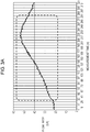
- FIG. 3A is a graph showing an example of a change in flow rate of a gas used for a fuel cell at a start of operation.
- FIG. 3B is a table showing later-described 8th-order period average flow rate Q8(n) and 32nd-order period average flow rate Q32(n) that are obtained from data about flow rates measured at measurement time (n) within a range enclosed with a dot-and-dash line in FIG. 3A , and increased flow rate ⁇ Q8 between 8th-order period average flow rate Q8(n) and previous 8th-order period average flow rate Q8(n-8) and increased flow rate ⁇ Q32.
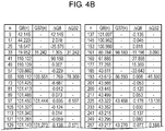
- FIGS. 4A are a graph showing an example of a change in flow rate of a gas used for a gas stove in operation, which is illustrated to draw a contrast between results of the fuel cell and the gas stove.
- FIG. 4B is a table showing later-described 8th-order period average flow rate Q8(n) and 32nd-order period average flow rate Q32(n) that are obtained from data about flow rates measured at measurement time (n) within a range enclosed with a dot-and-dash line in FIG.
- the vertical axis indicates flow rates [L/h]
- the horizontal axis indicates consecutive numbers assigned to flow rate data measured by flow rate measurer 102 at regular time intervals and represents measurement time (n) herein.
- Fuel cell determinator 106 extracts fuel cell determination flow rates including a fuel cell characteristic of a gradual flow rate rise from flow rate data calculated by arithmetic unit 105 and determines whether or not the extracted fuel cell determination flow rates satisfy the following three conditions to determine whether or not a fuel cell is in operation.
- Fuel cell determinator 106 determines that the fuel cell is in operation when the three conditions described above are satisfied.
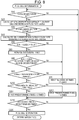
- step S10 the fuel cell determinator determines whether or not the first period, an 8th-order period, is set by period setting unit 104.
- arithmetic unit 105 averages 8 pieces of flow rate data included in one 8th-order period and calculates increased flow rate ⁇ Q8(n) between 8th-order period average flow rate Q8(n) and previous 8th-order period average flow rate Q8(n-8), i.e., between the first average flow rates in sequence, in step S20.
- the 8th-order period average flow rate is a value obtained every time measurement time n increases by 8.
- a minus sign indicates a decrease.
- step S30 the fuel cell determinator determines whether or not a 32nd-order period is set by period setting unit 104.
- arithmetic unit 105 calculates increased flow rate ⁇ Q32(n) between 32nd-order period average flow rate Q32(n) and previous 32nd-order period average flow rate Q8(n-8) in step S40.
- the 32nd-order period average flow rate is a value obtained every time measurement time n increases by 32.
- step S50 the fuel cell determinator determines whether or not 32nd-order period average flow rate ⁇ Q32(n) calculated in step S40 is within the first predetermined flow rate range, an element of condition (a).
- ⁇ Q32(n) is within the first predetermined flow rate range
- the fuel cell determinator increases a number of successive times by 1 in step S60.
- ⁇ Q32(n) is outside the range
- the fuel cell determinator resets the number of successive times to zero in step S70.
- step S80 the fuel cell determinator determines whether or not condition (b) is satisfied, i.e., 8th-order period average flow rate ⁇ Q8(n) is within the second predetermined flow rate range (e.g., greater than or equal to 0 L/h and less than 5 L/h) for the second predetermined times (e.g., 2 times) or more in the 32nd-order period.
- condition (b) i.e., 8th-order period average flow rate ⁇ Q8(n) is within the second predetermined flow rate range (e.g., greater than or equal to 0 L/h and less than 5 L/h) for the second predetermined times (e.g., 2 times) or more in the 32nd-order period.
- the process makes a transition to step S90. If not, the fuel cell determinator resets the number of successive times to zero in step S70.
- the process makes a transition to step S90.
- step S90 the fuel cell determinator determines whether or not 8th-order period average flow rate ⁇ Q8(n) is greater than or equal to the third predetermined flow rate (e.g., greater than or equal to 10 L/h) in the 32nd-order period.
- the process makes a transition to step S100. If it is, the fuel cell determinator resets the number of successive times to zero in step S70.
- the third predetermined flow rate e.g., not greater than or equal to 10 L/h
- step S100 the fuel cell determinator determines whether or not the number of successive times that has increased in step S60 reaches the first predetermined times (e.g., 5 times).
- gas meter 100 stores information about a fuel cell presence, i.e., information about the presence of a fuel cell in operation, in step S110.
- gas meter 100 stores information about a fuel cell absence, i.e., information about the absence of a fuel cell in operation, in step S120, and the process goes back to step S10 to repeat determination of whether or not a fuel cell is in operation.
- a new condition may be added in the determination process described above by similarly setting a 64th-order period made up of 2 pieces of 32nd-order periods and adding the new period so as to add the new condition that necessitates calculating 64th-order period average flow rates.
- the gas meter can determine whether or not a fuel cell is in operation based on period average flow rates.
- FIG. 6 shows an example of a hardware configuration of gas meter 100.
- gas meter 100 includes central processing unit (CPU) 210, memory 220, and flow rate meter 204.
- Flow rate meter 204 is an example of flow rate measurer 102 shown in FIG. 1 and may be a publicly known flow rate meter such as an ultrasonic flowmeter.
- CPU 210 executes computer program 221 stored in memory 220.
- Computer program 221 contains a description of the various steps described above.
- CPU 210 for example, executes various steps performed by arithmetic unit 105 and fuel cell determinator 106 shown in FIG. 1 .
- Memory 220 typically includes random-access memory (RAM) and read-only memory (ROM) and has, for example, data corresponding to the first predetermined flow rate range and the first predetermined times. Part of arithmetic unit 105 and fuel cell determinator 106 may constitute memory 220.
- Arithmetic unit 105 and fuel cell determinator 106 may be part of a single processor (CPU 210). Controller 110 may be set of an assemblage of a plurality of processors. Controller 110 may include at least one memory and a peripheral circuit. At least one memory may be disposed outside controller 110. For instance, fuel cell determinator 106 may be disposed outside controller 110. Gas meter 100 executes the various steps described above using CPU 210 and memory 220 (see FIG. 6 ) and thereby can discriminate an operating appliance with high accuracy.
- FIG. 7 is a block diagram showing a configuration of gas meter 200 that is a flow rate measurement device according to the present exemplary embodiment and differs from the block diagram of gas meter 100 of the first exemplary embodiment shown in FIG. 1 in that fuel cell installation information storage unit 107 is added.
- fuel cell installation information storage unit 107 stores information about whether or not a fuel cell is installed downstream of gas meter 200. Such information can be set up and stored in advance through electronic signals sent by operation of a switch (not shown) or communication when a fuel cell is installed. Alternatively, as described later, fuel cell installation information storage unit 107 may store information about installed fuel cell presence when fuel cell determinator 106 determines that a fuel cell is in operation.
- FIG. 8 is a flowchart of a process executed by fuel cell determinator 106 in the flow rate measurement device according to the present exemplary embodiment and differs from the process flowchart of FIG. 5 shown to illustrate the first exemplary embodiment in that step S100 and subsequent steps shown in FIG. 5 are replaced with steps S200 to S220. The following description is given of step S200 and subsequent steps.
- the fuel cell determinator determines that first 8th-order period average flow rate ⁇ Q8(n) is less than the third predetermined flow rate (e.g., less than 10 L/h) in the second 32nd-order period in step S90, the fuel cell determinator checks presence or absence of an installed fuel cell specified in fuel cell installation information storage unit 107 in step S200.
- the fuel cell determinator sets the first predetermined times, i.e., successive satisfaction times for conditions (a), (b), (c) established to determine that a fuel cell is in operation, to 3 times in step S201.
- the fuel cell determinator sets the first predetermined times to 5 times in step S202.
- step S210 if the number of the successive satisfaction times for conditions 1 to 3 is greater than or equal to the first predetermined times set in step S201 or step S202, the fuel cell determinator determines that the fuel cell is in operation (step S220). If the number of the successive times is less than the first predetermined times, the fuel cell determinator determines that the fuel cell is not in operation and returns to the process for determination again.
- fuel cell installation information storage unit 107 stores information about whether or not a fuel cell is installed downstream of gas meter 200. This enables the gas meter to determine early that a fuel cell is in operation when the fuel cell is installed.
- Gas flow rates measured by flow rate measurer 102 change (fluctuate) in some cases because of an installation environment and other factors. If such a change in flow rate occurs during determination of whether or not a fuel cell is in operation, the first predetermined times for which conditions (a) to (c) are satisfied are less likely to be in succession. This makes it difficult to determine that a fuel cell is in operation. However, a decrease in the number of the first predetermined times on condition that a fuel cell is installed enables the gas meter to determine early whether or not a fuel cell is in operation. This in turn facilitates determination of whether or not a fuel cell is in operation even in an installation environment where a change in flow rate occurs.
- technique in the present exemplary embodiment enables the gas meter to determine whether or not a fuel cell is in operation in a short span of time on condition that the fuel cell is installed. This reduces a chance that another gas appliance starts being used during determination of whether or not a fuel cell is in operation. This in turn increases accuracy with which the gas meter determines whether or not a fuel cell is in operation while the fuel cell is operating.
- this technique can be applied to cases such as the implementation of a charge policy including a discount on the price charged for an amount of a gas consumed by a fuel cell.
- Fuel cell installation information storage unit 107 may store information about installed fuel cell presence when fuel cell determinator 106 determines that a fuel cell is in operation. This eliminates the need for setting up such information in advance by switch operation or communication. In this case, the fuel cell determinator determines that a fuel cell is in operation with the first predetermined times set at 5 times for a first time and is allowed to determine that a fuel cell is in operation with the first predetermined times set at 3 times from a second time onward. This facilitates determination of whether or not a fuel cell is in operation even in an installation environment where a change in flow rate occurs.
- a flow rate measurement device can extract an appliance characteristic.
- this technique can be similarly applied to flow rate meters for industrial use and water meters to identify an appliance in use that is connected downstream of such a flow rate measurement device, as well as a group of the appliances.
Landscapes
- Engineering & Computer Science (AREA)
- Physics & Mathematics (AREA)
- Chemical & Material Sciences (AREA)
- General Physics & Mathematics (AREA)
- Fluid Mechanics (AREA)
- General Chemical & Material Sciences (AREA)
- Chemical Kinetics & Catalysis (AREA)
- Electrochemistry (AREA)
- Life Sciences & Earth Sciences (AREA)
- Sustainable Energy (AREA)
- Sustainable Development (AREA)
- Manufacturing & Machinery (AREA)
- Electromagnetism (AREA)
- Combustion & Propulsion (AREA)
- Mechanical Engineering (AREA)
- General Engineering & Computer Science (AREA)
- Fuel Cell (AREA)
- Measuring Volume Flow (AREA)
Applications Claiming Priority (3)
| Application Number | Priority Date | Filing Date | Title |
|---|---|---|---|
| JP2017166349 | 2017-08-31 | ||
| JP2018025603A JP6956320B2 (ja) | 2017-08-31 | 2018-02-16 | 流量計測装置 |
| PCT/JP2018/029849 WO2019044445A1 (fr) | 2017-08-31 | 2018-08-09 | Dispositif de mesure de débit |
Publications (3)
| Publication Number | Publication Date |
|---|---|
| EP3677879A1 true EP3677879A1 (fr) | 2020-07-08 |
| EP3677879A4 EP3677879A4 (fr) | 2020-08-26 |
| EP3677879B1 EP3677879B1 (fr) | 2022-07-20 |
Family
ID=65812809
Family Applications (1)
| Application Number | Title | Priority Date | Filing Date |
|---|---|---|---|
| EP18852370.8A Active EP3677879B1 (fr) | 2017-08-31 | 2018-08-09 | Dispositif de mesure de débit |
Country Status (3)
| Country | Link |
|---|---|
| EP (1) | EP3677879B1 (fr) |
| JP (1) | JP6956320B2 (fr) |
| CN (1) | CN111051825B (fr) |
Family Cites Families (10)
| Publication number | Priority date | Publication date | Assignee | Title |
|---|---|---|---|---|
| JP2005241405A (ja) * | 2004-02-26 | 2005-09-08 | Yazaki Corp | 電子式ガスメータ及びその流量変化判定方法 |
| JP2011096533A (ja) * | 2009-10-30 | 2011-05-12 | Toyota Motor Corp | 燃料電池システム |
| JP2012177666A (ja) * | 2011-02-04 | 2012-09-13 | Panasonic Corp | 流量計測装置 |
| JP5793693B2 (ja) * | 2011-04-05 | 2015-10-14 | パナソニックIpマネジメント株式会社 | 流量計測装置 |
| JP5793651B2 (ja) * | 2011-05-13 | 2015-10-14 | パナソニックIpマネジメント株式会社 | 流量計測装置 |
| JP5909715B2 (ja) * | 2011-10-18 | 2016-04-27 | パナソニックIpマネジメント株式会社 | 燃料使用器具判別装置、流量測定装置、ガスメータおよび燃料使用器具判別方法 |
| JP5914877B2 (ja) * | 2011-11-17 | 2016-05-11 | パナソニックIpマネジメント株式会社 | ガス流量検出装置及びガス流量検出方法 |
| JP2013221863A (ja) * | 2012-04-17 | 2013-10-28 | Panasonic Corp | 流体器具情報提供装置 |
| JP2013231599A (ja) * | 2012-04-27 | 2013-11-14 | Panasonic Corp | 燃料電池判別システム |
| JP6363553B2 (ja) * | 2015-04-08 | 2018-07-25 | 日本特殊陶業株式会社 | 流体状態検出装置 |
-
2018
- 2018-02-16 JP JP2018025603A patent/JP6956320B2/ja active Active
- 2018-08-09 EP EP18852370.8A patent/EP3677879B1/fr active Active
- 2018-08-09 CN CN201880053344.5A patent/CN111051825B/zh active Active
Also Published As
| Publication number | Publication date |
|---|---|
| JP2019045465A (ja) | 2019-03-22 |
| EP3677879B1 (fr) | 2022-07-20 |
| CN111051825A (zh) | 2020-04-21 |
| CN111051825B (zh) | 2021-11-30 |
| JP6956320B2 (ja) | 2021-11-02 |
| EP3677879A4 (fr) | 2020-08-26 |
Similar Documents
| Publication | Publication Date | Title |
|---|---|---|
| US11519613B2 (en) | Indicator generating method and predictive maintenance method for failure prediction for a water heating system, such water heating system, and beverage maker | |
| EP2498070B1 (fr) | Dispositif de mesure de débit | |
| CN107209040B (zh) | 流量测量装置 | |
| EP2498071B1 (fr) | Dispositif de mesure de débit | |
| CN102414948B (zh) | 用于监控保护功能的灵敏度的方法和设备 | |
| EP3677879B1 (fr) | Dispositif de mesure de débit | |
| US11215487B2 (en) | Flow rate measurement device | |
| CN108700446B (zh) | 流量测量装置 | |
| EP3404374B1 (fr) | Dispositif de mesure de débit | |
| JP5288188B2 (ja) | 超音波流量計 | |
| JP6381498B2 (ja) | 計量メータの状態変化検出装置及びプログラム | |
| EP2770256B1 (fr) | Dispositif de distinction d'instrument de consommation de carburant, dispositif de mesure d'écoulement, gazomètre, et procédé permettant de faire la distinction entre des instruments de consommation de carburant | |
| CN115790754B (zh) | 流量检测方法、装置、流量计、存储介质及程序产品 | |
| EP2840365B1 (fr) | Méthode de mesure de débit | |
| JP6719088B2 (ja) | 流量計測装置 | |
| JP2019144044A (ja) | ガス器具判別装置 | |
| JP7022891B2 (ja) | ガス器具判別装置 | |
| JP5310001B2 (ja) | 超音波ガスメータ | |
| JP6767806B2 (ja) | 流量計測装置 | |
| KR101537357B1 (ko) | 반도체 공정을 모니터링 하는 방법 및 장치 | |
| EP3499195A1 (fr) | Dispositif de mesure de débit | |
| CN113358192B (zh) | 检测流量计中的异常计量漂移 | |
| JP2019200057A (ja) | 流量計測装置 | |
| JP2009216712A (ja) | 流量計測装置および流量計測方法 | |
| JP2019052915A (ja) | ガス器具判別装置 |
Legal Events
| Date | Code | Title | Description |
|---|---|---|---|
| STAA | Information on the status of an ep patent application or granted ep patent |
Free format text: STATUS: THE INTERNATIONAL PUBLICATION HAS BEEN MADE |
|
| PUAI | Public reference made under article 153(3) epc to a published international application that has entered the european phase |
Free format text: ORIGINAL CODE: 0009012 |
|
| STAA | Information on the status of an ep patent application or granted ep patent |
Free format text: STATUS: REQUEST FOR EXAMINATION WAS MADE |
|
| 17P | Request for examination filed |
Effective date: 20191210 |
|
| AK | Designated contracting states |
Kind code of ref document: A1 Designated state(s): AL AT BE BG CH CY CZ DE DK EE ES FI FR GB GR HR HU IE IS IT LI LT LU LV MC MK MT NL NO PL PT RO RS SE SI SK SM TR |
|
| AX | Request for extension of the european patent |
Extension state: BA ME |
|
| A4 | Supplementary search report drawn up and despatched |
Effective date: 20200724 |
|
| RIC1 | Information provided on ipc code assigned before grant |
Ipc: G01F 15/075 20060101ALI20200720BHEP Ipc: G01F 3/22 20060101AFI20200720BHEP Ipc: H01M 8/0438 20160101ALI20200720BHEP Ipc: G01F 15/06 20060101ALI20200720BHEP Ipc: G01F 1/66 20060101ALN20200720BHEP Ipc: F23N 5/18 20060101ALI20200720BHEP |
|
| DAV | Request for validation of the european patent (deleted) | ||
| DAX | Request for extension of the european patent (deleted) | ||
| GRAP | Despatch of communication of intention to grant a patent |
Free format text: ORIGINAL CODE: EPIDOSNIGR1 |
|
| STAA | Information on the status of an ep patent application or granted ep patent |
Free format text: STATUS: GRANT OF PATENT IS INTENDED |
|
| RIC1 | Information provided on ipc code assigned before grant |
Ipc: G01F 3/00 20060101ALN20220223BHEP Ipc: G01F 1/66 20060101ALN20220223BHEP Ipc: H01M 8/0438 20160101ALI20220223BHEP Ipc: G01F 15/075 20060101ALI20220223BHEP Ipc: G01F 15/06 20060101ALI20220223BHEP Ipc: F23N 5/18 20060101ALI20220223BHEP Ipc: G01F 3/22 20060101AFI20220223BHEP |
|
| INTG | Intention to grant announced |
Effective date: 20220315 |
|
| RIN1 | Information on inventor provided before grant (corrected) |
Inventor name: YOKOHATA, MITSUO Inventor name: KITANO, YUSUKE |
|
| GRAS | Grant fee paid |
Free format text: ORIGINAL CODE: EPIDOSNIGR3 |
|
| GRAA | (expected) grant |
Free format text: ORIGINAL CODE: 0009210 |
|
| STAA | Information on the status of an ep patent application or granted ep patent |
Free format text: STATUS: THE PATENT HAS BEEN GRANTED |
|
| AK | Designated contracting states |
Kind code of ref document: B1 Designated state(s): AL AT BE BG CH CY CZ DE DK EE ES FI FR GB GR HR HU IE IS IT LI LT LU LV MC MK MT NL NO PL PT RO RS SE SI SK SM TR |
|
| REG | Reference to a national code |
Ref country code: CH Ref legal event code: EP |
|
| REG | Reference to a national code |
Ref country code: DE Ref legal event code: R096 Ref document number: 602018038283 Country of ref document: DE |
|
| REG | Reference to a national code |
Ref country code: AT Ref legal event code: REF Ref document number: 1505796 Country of ref document: AT Kind code of ref document: T Effective date: 20220815 |
|
| REG | Reference to a national code |
Ref country code: IE Ref legal event code: FG4D |
|
| REG | Reference to a national code |
Ref country code: LT Ref legal event code: MG9D |
|
| REG | Reference to a national code |
Ref country code: NL Ref legal event code: MP Effective date: 20220720 |
|
| PG25 | Lapsed in a contracting state [announced via postgrant information from national office to epo] |
Ref country code: SE Free format text: LAPSE BECAUSE OF FAILURE TO SUBMIT A TRANSLATION OF THE DESCRIPTION OR TO PAY THE FEE WITHIN THE PRESCRIBED TIME-LIMIT Effective date: 20220720 Ref country code: RS Free format text: LAPSE BECAUSE OF FAILURE TO SUBMIT A TRANSLATION OF THE DESCRIPTION OR TO PAY THE FEE WITHIN THE PRESCRIBED TIME-LIMIT Effective date: 20220720 Ref country code: PT Free format text: LAPSE BECAUSE OF FAILURE TO SUBMIT A TRANSLATION OF THE DESCRIPTION OR TO PAY THE FEE WITHIN THE PRESCRIBED TIME-LIMIT Effective date: 20221121 Ref country code: NO Free format text: LAPSE BECAUSE OF FAILURE TO SUBMIT A TRANSLATION OF THE DESCRIPTION OR TO PAY THE FEE WITHIN THE PRESCRIBED TIME-LIMIT Effective date: 20221020 Ref country code: NL Free format text: LAPSE BECAUSE OF FAILURE TO SUBMIT A TRANSLATION OF THE DESCRIPTION OR TO PAY THE FEE WITHIN THE PRESCRIBED TIME-LIMIT Effective date: 20220720 Ref country code: LV Free format text: LAPSE BECAUSE OF FAILURE TO SUBMIT A TRANSLATION OF THE DESCRIPTION OR TO PAY THE FEE WITHIN THE PRESCRIBED TIME-LIMIT Effective date: 20220720 Ref country code: LT Free format text: LAPSE BECAUSE OF FAILURE TO SUBMIT A TRANSLATION OF THE DESCRIPTION OR TO PAY THE FEE WITHIN THE PRESCRIBED TIME-LIMIT Effective date: 20220720 Ref country code: FI Free format text: LAPSE BECAUSE OF FAILURE TO SUBMIT A TRANSLATION OF THE DESCRIPTION OR TO PAY THE FEE WITHIN THE PRESCRIBED TIME-LIMIT Effective date: 20220720 Ref country code: ES Free format text: LAPSE BECAUSE OF FAILURE TO SUBMIT A TRANSLATION OF THE DESCRIPTION OR TO PAY THE FEE WITHIN THE PRESCRIBED TIME-LIMIT Effective date: 20220720 |
|
| REG | Reference to a national code |
Ref country code: AT Ref legal event code: MK05 Ref document number: 1505796 Country of ref document: AT Kind code of ref document: T Effective date: 20220720 |
|
| PG25 | Lapsed in a contracting state [announced via postgrant information from national office to epo] |
Ref country code: PL Free format text: LAPSE BECAUSE OF FAILURE TO SUBMIT A TRANSLATION OF THE DESCRIPTION OR TO PAY THE FEE WITHIN THE PRESCRIBED TIME-LIMIT Effective date: 20220720 Ref country code: IS Free format text: LAPSE BECAUSE OF FAILURE TO SUBMIT A TRANSLATION OF THE DESCRIPTION OR TO PAY THE FEE WITHIN THE PRESCRIBED TIME-LIMIT Effective date: 20221120 Ref country code: HR Free format text: LAPSE BECAUSE OF FAILURE TO SUBMIT A TRANSLATION OF THE DESCRIPTION OR TO PAY THE FEE WITHIN THE PRESCRIBED TIME-LIMIT Effective date: 20220720 Ref country code: GR Free format text: LAPSE BECAUSE OF FAILURE TO SUBMIT A TRANSLATION OF THE DESCRIPTION OR TO PAY THE FEE WITHIN THE PRESCRIBED TIME-LIMIT Effective date: 20221021 |
|
| REG | Reference to a national code |
Ref country code: CH Ref legal event code: PL |
|
| REG | Reference to a national code |
Ref country code: DE Ref legal event code: R097 Ref document number: 602018038283 Country of ref document: DE |
|
| PG25 | Lapsed in a contracting state [announced via postgrant information from national office to epo] |
Ref country code: SM Free format text: LAPSE BECAUSE OF FAILURE TO SUBMIT A TRANSLATION OF THE DESCRIPTION OR TO PAY THE FEE WITHIN THE PRESCRIBED TIME-LIMIT Effective date: 20220720 Ref country code: RO Free format text: LAPSE BECAUSE OF FAILURE TO SUBMIT A TRANSLATION OF THE DESCRIPTION OR TO PAY THE FEE WITHIN THE PRESCRIBED TIME-LIMIT Effective date: 20220720 Ref country code: MC Free format text: LAPSE BECAUSE OF FAILURE TO SUBMIT A TRANSLATION OF THE DESCRIPTION OR TO PAY THE FEE WITHIN THE PRESCRIBED TIME-LIMIT Effective date: 20220720 Ref country code: LU Free format text: LAPSE BECAUSE OF NON-PAYMENT OF DUE FEES Effective date: 20220809 Ref country code: LI Free format text: LAPSE BECAUSE OF NON-PAYMENT OF DUE FEES Effective date: 20220831 Ref country code: DK Free format text: LAPSE BECAUSE OF FAILURE TO SUBMIT A TRANSLATION OF THE DESCRIPTION OR TO PAY THE FEE WITHIN THE PRESCRIBED TIME-LIMIT Effective date: 20220720 Ref country code: CZ Free format text: LAPSE BECAUSE OF FAILURE TO SUBMIT A TRANSLATION OF THE DESCRIPTION OR TO PAY THE FEE WITHIN THE PRESCRIBED TIME-LIMIT Effective date: 20220720 Ref country code: CH Free format text: LAPSE BECAUSE OF NON-PAYMENT OF DUE FEES Effective date: 20220831 Ref country code: AT Free format text: LAPSE BECAUSE OF FAILURE TO SUBMIT A TRANSLATION OF THE DESCRIPTION OR TO PAY THE FEE WITHIN THE PRESCRIBED TIME-LIMIT Effective date: 20220720 |
|
| REG | Reference to a national code |
Ref country code: BE Ref legal event code: MM Effective date: 20220831 |
|
| PLBE | No opposition filed within time limit |
Free format text: ORIGINAL CODE: 0009261 |
|
| STAA | Information on the status of an ep patent application or granted ep patent |
Free format text: STATUS: NO OPPOSITION FILED WITHIN TIME LIMIT |
|
| PG25 | Lapsed in a contracting state [announced via postgrant information from national office to epo] |
Ref country code: SK Free format text: LAPSE BECAUSE OF FAILURE TO SUBMIT A TRANSLATION OF THE DESCRIPTION OR TO PAY THE FEE WITHIN THE PRESCRIBED TIME-LIMIT Effective date: 20220720 Ref country code: EE Free format text: LAPSE BECAUSE OF FAILURE TO SUBMIT A TRANSLATION OF THE DESCRIPTION OR TO PAY THE FEE WITHIN THE PRESCRIBED TIME-LIMIT Effective date: 20220720 |
|
| 26N | No opposition filed |
Effective date: 20230421 |
|
| PG25 | Lapsed in a contracting state [announced via postgrant information from national office to epo] |
Ref country code: AL Free format text: LAPSE BECAUSE OF FAILURE TO SUBMIT A TRANSLATION OF THE DESCRIPTION OR TO PAY THE FEE WITHIN THE PRESCRIBED TIME-LIMIT Effective date: 20220720 |
|
| PG25 | Lapsed in a contracting state [announced via postgrant information from national office to epo] |
Ref country code: IE Free format text: LAPSE BECAUSE OF NON-PAYMENT OF DUE FEES Effective date: 20220809 |
|
| PG25 | Lapsed in a contracting state [announced via postgrant information from national office to epo] |
Ref country code: SI Free format text: LAPSE BECAUSE OF FAILURE TO SUBMIT A TRANSLATION OF THE DESCRIPTION OR TO PAY THE FEE WITHIN THE PRESCRIBED TIME-LIMIT Effective date: 20220720 |
|
| PG25 | Lapsed in a contracting state [announced via postgrant information from national office to epo] |
Ref country code: BE Free format text: LAPSE BECAUSE OF NON-PAYMENT OF DUE FEES Effective date: 20220831 |
|
| PG25 | Lapsed in a contracting state [announced via postgrant information from national office to epo] |
Ref country code: CY Free format text: LAPSE BECAUSE OF FAILURE TO SUBMIT A TRANSLATION OF THE DESCRIPTION OR TO PAY THE FEE WITHIN THE PRESCRIBED TIME-LIMIT Effective date: 20220720 |
|
| PG25 | Lapsed in a contracting state [announced via postgrant information from national office to epo] |
Ref country code: MK Free format text: LAPSE BECAUSE OF FAILURE TO SUBMIT A TRANSLATION OF THE DESCRIPTION OR TO PAY THE FEE WITHIN THE PRESCRIBED TIME-LIMIT Effective date: 20220720 Ref country code: IT Free format text: LAPSE BECAUSE OF FAILURE TO SUBMIT A TRANSLATION OF THE DESCRIPTION OR TO PAY THE FEE WITHIN THE PRESCRIBED TIME-LIMIT Effective date: 20220720 Ref country code: HU Free format text: LAPSE BECAUSE OF FAILURE TO SUBMIT A TRANSLATION OF THE DESCRIPTION OR TO PAY THE FEE WITHIN THE PRESCRIBED TIME-LIMIT; INVALID AB INITIO Effective date: 20180809 |
|
| PG25 | Lapsed in a contracting state [announced via postgrant information from national office to epo] |
Ref country code: TR Free format text: LAPSE BECAUSE OF FAILURE TO SUBMIT A TRANSLATION OF THE DESCRIPTION OR TO PAY THE FEE WITHIN THE PRESCRIBED TIME-LIMIT Effective date: 20220720 |
|
| PG25 | Lapsed in a contracting state [announced via postgrant information from national office to epo] |
Ref country code: BG Free format text: LAPSE BECAUSE OF FAILURE TO SUBMIT A TRANSLATION OF THE DESCRIPTION OR TO PAY THE FEE WITHIN THE PRESCRIBED TIME-LIMIT Effective date: 20220720 |
|
| PG25 | Lapsed in a contracting state [announced via postgrant information from national office to epo] |
Ref country code: MT Free format text: LAPSE BECAUSE OF FAILURE TO SUBMIT A TRANSLATION OF THE DESCRIPTION OR TO PAY THE FEE WITHIN THE PRESCRIBED TIME-LIMIT Effective date: 20220720 |
|
| PGFP | Annual fee paid to national office [announced via postgrant information from national office to epo] |
Ref country code: DE Payment date: 20250820 Year of fee payment: 8 |
|
| PGFP | Annual fee paid to national office [announced via postgrant information from national office to epo] |
Ref country code: GB Payment date: 20250820 Year of fee payment: 8 |
|
| PGFP | Annual fee paid to national office [announced via postgrant information from national office to epo] |
Ref country code: FR Payment date: 20250828 Year of fee payment: 8 |
|
| REG | Reference to a national code |
Ref country code: DE Ref legal event code: R084 Ref document number: 602018038283 Country of ref document: DE |
|
| REG | Reference to a national code |
Ref country code: GB Ref legal event code: 746 Effective date: 20260320 |