EP3678203B1 - Procédé de fabrication de dispositif électronique organique - Google Patents
Procédé de fabrication de dispositif électronique organique Download PDFInfo
- Publication number
- EP3678203B1 EP3678203B1 EP18852104.1A EP18852104A EP3678203B1 EP 3678203 B1 EP3678203 B1 EP 3678203B1 EP 18852104 A EP18852104 A EP 18852104A EP 3678203 B1 EP3678203 B1 EP 3678203B1
- Authority
- EP
- European Patent Office
- Prior art keywords
- ink composition
- organic electronic
- electronic device
- curing
- present application
- Prior art date
- Legal status (The legal status is an assumption and is not a legal conclusion. Google has not performed a legal analysis and makes no representation as to the accuracy of the status listed.)
- Active
Links
Images
Classifications
-
- H—ELECTRICITY
- H10—SEMICONDUCTOR DEVICES; ELECTRIC SOLID-STATE DEVICES NOT OTHERWISE PROVIDED FOR
- H10K—ORGANIC ELECTRIC SOLID-STATE DEVICES
- H10K59/00—Integrated devices, or assemblies of multiple devices, comprising at least one organic light-emitting element covered by group H10K50/00
- H10K59/80—Constructional details
- H10K59/87—Passivation; Containers; Encapsulations
- H10K59/873—Encapsulations
- H10K59/8731—Encapsulations multilayered coatings having a repetitive structure, e.g. having multiple organic-inorganic bilayers
-
- H—ELECTRICITY
- H10—SEMICONDUCTOR DEVICES; ELECTRIC SOLID-STATE DEVICES NOT OTHERWISE PROVIDED FOR
- H10K—ORGANIC ELECTRIC SOLID-STATE DEVICES
- H10K71/00—Manufacture or treatment specially adapted for the organic devices covered by this subclass
- H10K71/40—Thermal treatment, e.g. annealing in the presence of a solvent vapour
-
- H—ELECTRICITY
- H10—SEMICONDUCTOR DEVICES; ELECTRIC SOLID-STATE DEVICES NOT OTHERWISE PROVIDED FOR
- H10K—ORGANIC ELECTRIC SOLID-STATE DEVICES
- H10K71/00—Manufacture or treatment specially adapted for the organic devices covered by this subclass
-
- H—ELECTRICITY
- H10—SEMICONDUCTOR DEVICES; ELECTRIC SOLID-STATE DEVICES NOT OTHERWISE PROVIDED FOR
- H10K—ORGANIC ELECTRIC SOLID-STATE DEVICES
- H10K50/00—Organic light-emitting devices
- H10K50/80—Constructional details
- H10K50/84—Passivation; Containers; Encapsulations
- H10K50/844—Encapsulations
-
- H—ELECTRICITY
- H10—SEMICONDUCTOR DEVICES; ELECTRIC SOLID-STATE DEVICES NOT OTHERWISE PROVIDED FOR
- H10K—ORGANIC ELECTRIC SOLID-STATE DEVICES
- H10K50/00—Organic light-emitting devices
- H10K50/80—Constructional details
- H10K50/84—Passivation; Containers; Encapsulations
- H10K50/846—Passivation; Containers; Encapsulations comprising getter material or desiccants
-
- H—ELECTRICITY
- H10—SEMICONDUCTOR DEVICES; ELECTRIC SOLID-STATE DEVICES NOT OTHERWISE PROVIDED FOR
- H10K—ORGANIC ELECTRIC SOLID-STATE DEVICES
- H10K71/00—Manufacture or treatment specially adapted for the organic devices covered by this subclass
- H10K71/10—Deposition of organic active material
- H10K71/12—Deposition of organic active material using liquid deposition, e.g. spin coating
- H10K71/13—Deposition of organic active material using liquid deposition, e.g. spin coating using printing techniques, e.g. ink-jet printing or screen printing
- H10K71/135—Deposition of organic active material using liquid deposition, e.g. spin coating using printing techniques, e.g. ink-jet printing or screen printing using ink-jet printing
-
- Y—GENERAL TAGGING OF NEW TECHNOLOGICAL DEVELOPMENTS; GENERAL TAGGING OF CROSS-SECTIONAL TECHNOLOGIES SPANNING OVER SEVERAL SECTIONS OF THE IPC; TECHNICAL SUBJECTS COVERED BY FORMER USPC CROSS-REFERENCE ART COLLECTIONS [XRACs] AND DIGESTS
- Y02—TECHNOLOGIES OR APPLICATIONS FOR MITIGATION OR ADAPTATION AGAINST CLIMATE CHANGE
- Y02E—REDUCTION OF GREENHOUSE GAS [GHG] EMISSIONS, RELATED TO ENERGY GENERATION, TRANSMISSION OR DISTRIBUTION
- Y02E10/00—Energy generation through renewable energy sources
- Y02E10/50—Photovoltaic [PV] energy
- Y02E10/549—Organic PV cells
Definitions
- the present application relates to a method for preparing an organic electronic device and an organic electronic device.
- An organic electronic device means a device comprising a layer of an organic material that generates an alternating current of electric charges using holes and electrons, and an example thereof can include a photovoltaic device, a rectifier, a transmitter and an organic light emitting diode (OLED), and the like.
- the organic light emitting diode (OLED) among the organic electronic devices has lower power consumption and faster response speed, than conventional light sources, and is advantageous for thinning display devices or illuminations.
- the OLED has excellent space utilization, so that it is expected to be applied in various fields covering various portable devices, monitors, notebooks, and televisions.
- OLEDs In commercialization and application expansion of OLEDs, the most important problem is a durability problem. Organic materials and metal electrodes, and the like, contained in OLEDs are very easily oxidized by external factors such as moisture. Thus, products comprising OLEDs are highly sensitive to environmental factors. Accordingly, various methods have been proposed to effectively block penetration of oxygen or moisture from the outside into organic electronic devices such as OLEDs.
- US 2015/357570 A1 disclose an encapsulation composition, an encapsulation film including the same, an encapsulation product for organic electronic devices, and a method of manufacturing an organic electronic device are provided.
- the encapsulation composition can be useful in effectively preventing moisture or oxygen from flowing into the organic electronic device from external environments while realizing transparency when the organic electronic device is encapsulated by the encapsulation composition.
- the encapsulation film formed of the encapsulation composition can be useful in ensuring mechanical properties such as handling properties and processability, and the organic electronic device whose encapsulation structure is formed by means of the encapsulation film may have improved lifespan and durability, thereby providing an encapsulation product for organic electronic devices showing high reliability.
- JP 2015 025877 A discloses an image display device, having a protective unit, which offers little display defect and superior visibility by moderating contraction stress of a cured resin layer through use of an optical film with a functional layer.
- KR 2016 0114539 A discloses an adhesive composition and an organic electronic apparatus comprising the same.
- the adhesive composition has a structure which can effectively block moisture or oxygen flowing into an organic electronic apparatus from the outside, enables the implement of a a front surface emission type organic electronic apparatus and has excellent handling properties and processability.
- JP 2015 062166 A discloses a moisture catcher-forming composition for organic EL elements which can be handled in the air, and a moisture catcher which can be handled in the air, thereby providing an organic EL element.
- the present invention relates to a method for preparing an organic electronic device, which provides a method for preparing an organic electronic device that can effectively block moisture or oxygen introduced from the outside into an organic electronic device, is excellent in flatness of a sealing film and can minimize an out-gas amount occurring in a sealing process, and an organic electronic device.
- the present application relates to a method for preparing an organic electronic device.
- the step of applying an ink composition can comprise ejecting an ink composition using an inkjet apparatus.
- the inkjet process can be applied to sealing or encapsulating organic electronic devices such as, for example, OLEDs.
- organic electronic device means an article or device having a structure comprising an organic material layer that generates an alternating current of electric charges using holes and electrons between a pair of electrodes facing each other, and an example thereof can include a photovoltaic device, a rectifier, a transmitter and an organic light emitting diode (OLED), and the like, but is not limited thereto.
- the organic electronic device can be an OLED.
- the ink composition is a solventless type. Furthermore, the ink composition is a photocurable composition.
- the present application minimizes the content of volatile organic compounds or ionic substances contained by using an organic solvent to minimize the out-gas amount in the sealing process, whereby the reliability of the organic electronic device can be ensured.
- the out-gas amount measured using Purge & Trap-gas chromatography/mass spectrometry can be less than 150ppm, less than 100ppm or less than 50ppm. More specifically, after the ink composition is cured and the cured product is maintained at 110°C for 30 minutes, the out-gas can be measured by using a Purge & Trap sampler (JAI JTD-505III)-GC/MS (Agilent 7890b/5977a) instrument with Purge & Trap-gas chromatography/mass spectrometry for cured samples.
- the sample to be measured can be an ink composition applied on a substrate, where it can be measured, for example, on a 50mg sample. The lower limit thereof is not particularly limited, which can be 0ppm or 10ppm.
- the term "out-gas” can be generically referred to as materials which are present in an uncured state even after curing, such as volatile organic compounds or ionic materials present in the ink composition.
- the volatile organic compound can be defined as all organic compounds present in the gas phase in the atmosphere. It is used to collectively mean all organic substances that can exist in a gas state at room temperature and normal pressure, such as hydrocarbons composed of only carbon and hydrogen, halogenated hydrocarbons and nitrogen or sulfur-containing hydrocarbons, and in a broad sense, it can also include semi-volatile organic compounds.
- the volatile organic compounds can be organic solvents, thermal decomposition by-products of curing agents, or by-products generated by addition reaction.
- the ionic substance is not particularly limited as long as it is a substance which can cause wiring corrosion of the organic electronic device, and for example, it can be a halogen ion and can be a chlorine ion.
- the halogen ion as the ionic material can cause electrochemical corrosion of the organic electronic device, so that the damage to the organic electronic device can be prevented by controlling the content to a minimum.
- P&T can mean a VOC (volatile organic compounds) pre-treatment instrument or method in which trace amounts of volatile organic compounds present in a sample are extracted and concentrated to transfer to gas chromatography (GC) or gas chromatography/mass spectrometry (GC/MS).
- GC gas chromatography
- GC/MS gas chromatography/mass spectrometry
- the gas chromatography/mass spectrometry means a separation apparatus or a method thereof for distinguishing contents of a solution in various samples.
- the GC/MS is coupled by gas chromatography (GC) used to separate various compounds and a mass spectrometer (MS) for measuring atomic mass of a substance coming from the GC.
- GC gas chromatography
- MS mass spectrometer
- the GC/MS is connected to a computer in which specific type libraries of compounds are stored and thus does not only identify concentrations, but also types of substances as compared with the libraries identifying compounds in a solution. Continuous investigations after identifying the presence of the compound generally analyze the specific substance using the GC.
- the material of the ink composition applied to the above preparation method is a solventless type photo-curable composition.
- the above-described preparation method of the present application can provide an organic electronic device having high reliability by being particularly applied to an ink composition of a specific composition to be described below.
- An exemplary ink composition can comprise an epoxy compound and a compound having an oxetane group.
- the epoxy compound can be a photo-curable or thermosetting compound.
- the compound having an oxetane group can be included in a range of 45 parts by weight to 145 parts by weight, 48 parts by weight to 143 parts by weight or 63 parts by weight to 132 parts by weight relative to 100 parts by weight of the epoxy compound.
- the present application can form an organic layer on an organic electronic element by an inkjet method, makes it possible for the applied ink composition to have excellent spreadability in a short time, and can provide an organic layer having excellent curing sensitivity after curing.
- the ink composition can comprise a photoinitiator.
- the ink composition can realize excellent adhesive strength and curing sensitivity as well as processability as an ink composition together with the epoxy compound and the oxetane group-containing compound as described above.
- the epoxy compound can have at least bifunctionality or more. That is, two or more epoxy functional groups can be present in the compound.
- the epoxy compound realizes excellent heat resistance at high temperature and high humidity by realizing an appropriate degree of crosslinking in a sealing material.
- the epoxy compound can comprise a compound having a cyclic structure in its molecular structure and/or a linear or branched aliphatic compound. That is, the ink composition of the present application can comprise at least one of a compound having a cyclic structure in its molecular structure and a linear or branched aliphatic compound as an epoxy compound, and can comprise them together.
- the compound having a cyclic structure in its molecular structure can have ring constituent atoms in the molecular structure in a range of 3 to 10, 4 to 8, or 5 to 7, and two or more cyclic structures can be present in the compound.
- the linear or branched aliphatic compound can be included in the ink composition in a range of 20 parts by weight to 200 parts by weight, 23 parts by weight to 190 parts by weight, 25 parts by weight to 180 parts by weight, 29 parts by weight to 175 parts by weight, or 32 parts by weight to 173 parts by weight, relative to 100 parts by weight of the compound having a cyclic structure.
- the present application makes it possible for the ink composition to have suitable physical properties in sealing the entire surface of an organic electronic element, to have excellent curing strength after curing and also to realize excellent moisture barrier properties together.
- the linear or branched aliphatic compound can have an epoxy equivalent in a range of 120g/eq to 375 g/eq or 120 g/eq to 250 g/eq.
- the present application can prevent the viscosity of the composition from becoming too high to render the inkjet process impossible while improving the degree of curing completion after curing of the sealing material.
- the epoxy compound can have an epoxy equivalent in a range of 50 to 350g/eq, 73 to 332g/eq, 94 to 318g/eq, or 123 to 298g/eq.
- the compound having an oxetane group can have a weight average molecular weight in a range of 150 to 1,000g/mol, 173 to 980g/mol, 188 to 860g/mol, 210 to 823g/mol or 330 to 780g/mol.
- the present application can realize an excellent printing property when applied to inkjet printing and simultaneously provide moisture barrier properties and excellent curing sensitivity.
- the weight average molecular weight can mean a value converted to standard polystyrene measured by GPC (gel permeation chromatography).
- the epoxy equivalent is also grams (g/eq) of the resin containing one gram equivalent of an epoxy group, which can be measured according to the method defined in JIS K 7236.
- the compound having an oxetane group can have a boiling point in a range of 90 to 300°C, 98 to 270°C, 110 to 258°C, or 138 to 237°C.
- the present application can provide a sealing material which can have excellent moisture barrier properties from the outside while realizing excellent printability even at a high temperature in an inkjet process, and prevent damage applied to the element due to suppressed outgas.
- the boiling point can be measured at 1 atm, unless otherwise specified.
- the compound having a cyclic structure in its molecular structure can be exemplified by a alicyclic epoxy compound.
- the compound can be exemplified by 3,4-epoxycyclohexylmethyl 3',4'-epoxycyclohexanecarboxylate (EEC) and derivatives, dicyclopentadiene dioxide and derivatives, vinylcyclohexene dioxide and derivatives, or 1,4-cyclohexanedimethanol bis(3,4-epoxycyclohexanecarboxylate) and derivatives, but is not limited thereto.
- EEC 3,4-epoxycyclohexylmethyl 3',4'-epoxycyclohexanecarboxylate
- dicyclopentadiene dioxide and derivatives vinylcyclohexene dioxide and derivatives
- vinylcyclohexene dioxide and derivatives or 1,4-cyclohexanedimethanol bis(3,4-epoxycyclohexanecarboxy
- the structure is not limited, and for example, OXT-221, CHOX, OX-SC, OXT101, OXT121, OXT221 or OXT212 from TOAGOSEI, or EHO, OXBP, OXTP or OXMA from ETERNACOLL can be exemplified.
- the linear or branched aliphatic epoxy compound can include aliphatic glycidyl ether, 1,4-butanediol diglycidyl ether, ethylene glycol diglycidyl ether, 1,6-hexanediol diglycidyl ether, propylene glycol diglycidyl ether, diethylene glycol diglycidyl ether, butyl glycidyl ether, 2-ethylhexyl glycidyl ether or neopentyl glycol diglycidyl ether, but is not limited thereto.
- the ink composition can further comprise a photoinitiator.
- the photoinitiator can be a cationic photopolymerization initiator.
- the photoinitiator can be a compound that absorbs a wavelength in a range of 200nm to 400nm.
- the cationic photopolymerization initiator a known material in the art can be used and for example, it can include a compound having a cation moiety comprising aromatic sulfonium, aromatic iodonium, aromatic diazonium or aromatic ammonium and an anion moiety comprising AsF 6 - , SbF 6 - , PF 6 - , or tetrakis(pentafluorophenyl) borate.
- an ionized cationic initiator of onium salt or organometallic salt series or a non-ionized cationic photopolymerization initiator of organic silane or latent sulfonic acid series can be used.
- a diaryliodonium salt, a triarylsulfonium salt or an aryldiazonium salt and the like can be exemplified as the initiator of the onium salt series
- iron arene or the like can be exemplified as the initiator of the organometallic salt series
- o-nitrobenzyl triaryl silyl ether, triaryl silyl peroxide or an acyl silane and the like can be exemplified as the initiator of the organosilane series
- ⁇ -sulfonyloxy ketone or ⁇ -hydroxymethylbenzoin sulfonate and the like can be exemplified as the initiator of the latent sulfuric acid series, without being limited thereto.
- the encapsulating composition of the present application can comprise a photoinitiator comprising an iodonium salt or a sulfonium salt as a photoinitiator in the above-mentioned specific composition, so as to be suitable for use in sealing an organic electronic element by an inkjet method.
- a photoinitiator comprising an iodonium salt or a sulfonium salt as a photoinitiator in the above-mentioned specific composition, so as to be suitable for use in sealing an organic electronic element by an inkjet method.
- the encapsulating composition according to the above composition is directly sealed on the organic electronic element, it is possible to prevent chemical damage from being applied to the element due to a small amount of generated outgas.
- the photoinitiator also has excellent solubility, which can be suitably applied to an inkjet process.
- the photoinitiator can be included in an amount of 1 to 15 parts by weight, 2 to 13 parts by weight, or 3 to 11 parts by weight relative to 100 parts by weight of the epoxy compound.
- the ink composition can further comprise a surfactant.
- the ink composition comprises a surfactant, so that it can be provided as a liquid ink having enhanced spreadability.
- the surfactant can comprise a polar functional group.
- the polar functional group can include, for example, a carboxyl group, a hydroxyl group, a phosphate, an ammonium salt, a carboxylate group, a sulfate or a sulfonate.
- the surfactant can be a non-silicone-based surfactant or a fluorine-based surfactant.
- the non-silicone-based surfactant or the fluorine-based surfactant can be applied together with the above-described epoxy compound and compound having an oxetane group to provide excellent coating properties on the organic electronic element.
- a surfactant containing a polar reactive group since it has high affinity with the other components of the ink composition, it can participate in the curing reaction, thereby realizing an excellent effect in terms of adhesion.
- a hydrophilic fluorine-based surfactant or non-silicone-based surfactant can be used to improve coating properties of a base material.
- the surfactant can be a polymer type or oligomer type fluorine-based surfactant.
- a commercially available product can be used, which can be selected from the group consisting of Glide 100, Glide 110, Glide 130, Glide 460, Glide 440, Glide 450 or RAD 2500 from TEGO, Megaface F-251, F-281, F-552, F554, F-560, F-561, F-562, F-563, F-565, F-568, F-570 and F-571 from DIC (DaiNippon Ink Chemicals), or Surflon S-111, S-112, S-113, S-121, S-131, S-132, S-141 and S-145 from Asahi Glass Co., Fluorad FC-93, FC-95, FC-98, FC-129, FC-135, FC-170C, FC-430 and FC-4430 from Sumitomo 3M Ltd., or Zonyl FS-
- the surfactant can be included in an amount of 0.1 to 10 parts by weight, 0.05 to 10 parts by weight, 0.1 to 10 parts by weight, 0.5 to 8 parts by weight or 1 to 4 parts by weight relative to 100 parts by weight of the curable compound.
- the present application allows the ink composition to be applied to an inkjet method, thereby forming a thin film organic layer.
- the ink composition can further comprise a photosensitizer in order to complement the curing property at a long wavelength activation energy beam of 300nm or more.
- the photosensitizer can be a compound that absorbs a wavelength in a range of 200nm to 400nm.
- the photosensitizer can be one or more selected from the group consisting of an anthracene-based compound such as anthracene, 9,10-dibutoxyanthracene, 9,10-dimethoxyanthracene, 9,10-diethoxyanthracene and 2-ethyl-9,10-dimethoxyanthracene; a benzophenone-based compound such as benzophenone, 4,4-bis(dimethylamino)benzophenone, 4,4-bis(diethylamino)benzophenone, 2,4,6-trimethylaminobenzophenone, methyl-o-benzolybenzoate, 3,3-dimethyl-4-methoxybenzophenone and 3,3,4,4-tetra(t-butylperoxycarbonyl)benzophenone; a ketone-based compound such as acetophenone, dimethoxyacetophenone, diethoxyacetophenone, 2-hydroxy-2-methyl-1-phenylpropan
- the photosensitizer can be included in an amount of 28 to 40 parts by weight, 31 to 38 parts by weight or 32 to 36 parts by weight relative to 100 parts by weight of the photoinitiator to be described below.
- the present application can prevent the photosensitizer from not dissolving to lower attachment force while realizing a synergistic effect of curing sensitivity at a desired wavelength.
- the ink composition of the present application can further comprise a coupling agent.
- the present application can improve adhesiveness of a cured product of the ink composition to an adherend or moisture transmission resistance of the cured product.
- the coupling agent can include, for example, a titanium-based coupling agent, an aluminum-based coupling agent, or a silane coupling agent.
- the silane coupling agent can include, specifically, an epoxy-based silane coupling agent such as 3-glycidyloxypropyltrimethoxysilane, 3-glycidyloxypropyltriethoxysilane, 3-glycidyloxypropyl (dimethoxy)methylsilane and 2-(3,4-epoxycyclohexyl)ethyltrimethoxysilane; a mercapto-based silane coupling agent such as 3-mercaptopropyltrimethoxysilane, 3-mercaptopropyltriethoxysilane, 3-mercaptopropylmethyldimethoxysilane and 11-mercaptoundecyltrimethoxysilane; an amino-based silane coupling agent such as 3-aminopropyltrimethoxysilane, 3-aminopropyltriethoxysilane, 3-aminopropyldimethoxymethylsilane, N-phenyl
- the coupling agent can be included in an amount of 0.1 to 10 parts by weight or 0.5 to 5 parts by weight, relative to 100 parts by weight of the epoxy compound. Within the above range, the present application can realize an effect of improving the adhesiveness by the addition of the coupling agent.
- the ink composition of the present application can comprise, if necessary, a moisture adsorbent.
- moisture adsorbent can be used to generically mean a component capable of adsorbing or removing moisture or humidity introduced from the outside through a physical or chemical reaction or the like. That is, it means a moisture-reactive adsorbent or a physical adsorbent, and a mixture thereof is also usable.
- a specific kind of the usable moisture adsorbent in the present application is not particularly limited, which can include, for example, one or a mixture of two or more of a metal oxide, a metal salt or phosphorus pentoxide (P 2 O 5 ), and the like, in the case of a moisture-reactive adsorbent, and can include zeolite, zirconia or montmorillonite, and the like, in the case of the physical adsorbent.
- the ink composition of the present application can comprise the moisture adsorbent in an amount of 5 parts by weight to 100 parts by weight, 5 to 80 parts by weight, 5 parts by weight to 70 parts by weight or 10 to 30 parts by weight, relative to 100 parts by weight of the epoxy compound.
- the ink composition of the present application preferably controls the content of the moisture adsorbent to 5 parts by weight or more, the present application can make the ink composition or the cured product thereof exhibit excellent moisture and humidity barrier properties.
- the present application can provide a thin film sealing structure.
- the ink composition can further comprise an inorganic filler, if necessary.
- an inorganic filler in the present application is not particularly limited, and for example, one or a mixture of two or more of clay, talc, alumina, calcium carbonate, silica, and the like can be used.
- the ink composition of the present application can comprise 0 to 50 parts by weight, 1 to 40 parts by weight, 1 to 20 parts by weight, or 1 to 10 parts by weight of inorganic filler, relative to 100 parts by weight of the epoxy compound.
- the present application can provide a sealing structure having excellent moisture or humidity barrier properties and mechanical properties by controlling the inorganic filler, preferably, to 1 part by weight or more. Furthermore, by controlling the content of the inorganic filler to 50 parts by weight or less, the present invention can provide a cured product exhibiting excellent moisture barrier properties even when formed into a thin film.
- the ink composition according to the present application can comprise various additives in the range without affecting the above-described effects of invention.
- the ink composition can comprise a defoamer, a tackifier, an ultraviolet stabilizer or an antioxidant and the like in an appropriate range of content depending on the desired physical properties.
- the ink composition can be in a liquid phase at room temperature, for example, at 15°C to 35°C or about 25°C.
- the ink composition can be in a solventless type liquid phase.
- the ink composition can be applied to seal an organic electronic element, and specifically, the ink composition can be an ink composition that can be applied to seal the entire surface of an organic electronic element.
- the present application can seal an organic electronic element by applying the composition on the side of the element with the inkjet method.
- the ink composition can have a viscosity, as measured by DV-3 from Brookfield, Inc. at a temperature of 25°C, 90% torque and a shear rate of 100 rpm, in a range of 50 cP or less, 1 to 46 cP, 3 to 44 cP, 4 to 38 cP, 5 to 33 cP or 14 to 24 cP.
- a viscosity as measured by DV-3 from Brookfield, Inc. at a temperature of 25°C, 90% torque and a shear rate of 100 rpm, in a range of 50 cP or less, 1 to 46 cP, 3 to 44 cP, 4 to 38 cP, 5 to 33 cP or 14 to 24 cP.
- the ink composition can have light transmittance of 90% or more, 92% or more, or 95% or more in the visible light region after curing.
- the present application provides an organic electronic device having high-resolution, low power consumption and long-life by applying the ink composition to a top emission type organic electronic device.
- the ink composition may not comprise the above-described moisture adsorbent or inorganic filler in consideration of the above-described optical characteristics.
- the ink composition of the present application can have a contact angle to glass of 30° or less, 25° or less, 20° or less, or 12° or less.
- the lower limit is not particularly limited, but can be 1° or 3° or more.
- the contact angle can be measured by applying a drop of the encapsulating composition onto glass using a sessile drop measurement method, which can be an average value measured after applying 5 times.
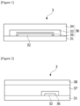
- An exemplary organic electronic device can comprise, as shown in Figure 1 , a substrate (31); an organic electronic element (32) formed on the substrate (31); and an organic layer (33) that seals the entire surface of the organic electronic element (32).
- the organic layer can have an out-gas amount of less than 150ppm, less than 100ppm or less than 50ppm as measured using Purge & Trap-gas chromatography/mass spectrometry after holding it at 110°C for 30 minutes. More specifically, after the cured organic layer is maintained at 110°C for 30 minutes, the out-gas can be measured with Purge & Trap-gas chromatography/mass spectrometry by using a Purge & Trap sampler (JAI JTD-505III)-GC/MS (Agilent 7890b/5977a) instrument.
- the organic electronic device can comprise an organic layer applied by the above-described preparation method.
- the present application provides an organic electronic device which has top attachment force by excellent flatness and can prevent damage to the element by the minimized out-gas amount.
- the organic electronic element can comprise a first electrode layer, an organic layer formed on the first electrode layer and containing at least a light emitting layer, and a second electrode layer formed on the organic layer.
- the first electrode layer can be a transparent electrode layer or a reflective electrode layer
- the second electrode layer can also be a transparent electrode layer or a reflective electrode layer.
- the organic electronic element can comprise a reflective electrode layer formed on a substrate, an organic layer formed on the reflective electrode layer and containing at least a light emitting layer, and a transparent electrode layer formed on the organic layer.
- the organic electronic element can be an organic light emitting diode.
- the organic electronic device according to the present application can be a top emission type, but is not limited thereto, and can be applied to a bottom emission type.
- the organic electronic device (3) can further comprise an inorganic protective layer (35) for protecting the electrodes and the light emitting layer of the organic electronic element (32).
- the inorganic protective layer can be an inorganic layer.
- the inorganic protective layer (35) can be present between the organic electronic element (32) and the above-described organic layer (33).
- the inorganic layer can be a protective layer formed by chemical vapor deposition (CVD). As the material, a known inorganic material can be used.
- the organic electronic device (3) can further comprise an inorganic layer (34) formed on the organic layer (33).
- the inorganic layer can be one or more metal oxides, nitrides or oxynitrides selected from the group consisting of Al, Zr, Ti, Hf, Ta, In, Sn, Zn and Si.
- the inorganic layer can have a thickness of 0.01 ⁇ m to 50 ⁇ m, 0.1 ⁇ m to 20 ⁇ m, or 1 ⁇ m to 10 ⁇ m.
- the inorganic layer of the present application can be an inorganic material without any dopant, or can be an inorganic material containing a dopant.
- the dopant which can be doped can be one or more elements selected from the group consisting of Ga, Si, Ge, Al, Sn, Ge, B, In, Tl, Sc, V, Cr, Mn, Fe, Co and Ni, or an oxide of the element, but is not limited thereto.
- the thickness of the organic layer can be in a range of 2 ⁇ m to 20 ⁇ m, 2.5 ⁇ m to 15 ⁇ m, and 2.8 ⁇ m to 11 ⁇ m.
- the present application can prevent damage to the element due to light by providing a thin organic layer to provide a thin film organic electronic device and simultaneously sufficiently curing it by the above-described light irradiation quantity.
- the organic electronic device of the present application can comprise a sealing structure containing the organic layer and the inorganic layer, as described above, where the sealing structure can comprise at least one or more organic layers and at least one or more inorganic layers, and the organic layer and the inorganic layer can be repeatedly laminated.
- the organic electronic device can have a structure of substrate/organic electronic element/inorganic protective layer/(organic layer/inorganic layer)n, where n can be a number in a range of 1 to 100.
- the organic electronic device of the present application can further comprise a cover substrate present on the organic layer.
- the material of the substrate and/or the cover substrate is not particularly limited, and a known material in the art can be used.
- the substrate or the cover substrate can be glass, a metal base material or a polymer film.
- polyethylene terephthalate film for example, a polyethylene terephthalate film, a polytetrafluoroethylene film, a polyethylene film, a polypropylene film, a polybutene film, a polybutadiene film, a vinyl chloride copolymer film, a polyurethane film, an ethylene-vinyl acetate film, an ethylene-propylene copolymer film, an ethylene-ethyl acrylate copolymer film, an ethylene-methyl acrylate copolymer film or a polyimide film and the like can be used.
- a polyethylene terephthalate film for example, a polytetrafluoroethylene film, a polyethylene film, a polypropylene film, a polybutene film, a polybutadiene film, a vinyl chloride copolymer film, a polyurethane film, an ethylene-vinyl acetate film, an ethylene-propylene copolymer film
- the organic electronic device (3) can further comprise a sealing film (37) existing between the cover substrate (38) and the substrate (31) on which the organic electronic element (32) is formed.
- the sealing film (37) can be applied as a use for attaching the substrate (31) on which the organic electronic element (32) is formed and the cover substrate (38), which can be, for example, a pressure-sensitive adhesive film or an adhesive film in a solid phase at room temperature, but is not limited thereto.
- the sealing film (37) can seal the entire surface of the sealing structure (36) of the above-described organic layer and inorganic layer, laminated on the organic electronic element (32).
- the present invention relates to a method for preparing an organic electronic device, which provides a method for preparing an organic electronic device that can effectively block moisture or oxygen introduced from the outside into an organic electronic device, is excellent in flatness of a sealing film and can minimize an out-gas amount occurring in a sealing process, and an organic electronic device.
- Figures 1 and 2 are cross-sectional views showing an organic electronic device according to one example of the present invention.
- An alicyclic epoxy compound (Celloxide 2021P, Daicel Corp.) and an aliphatic epoxy compound (DE200, HAJIN CHEM TECH) as epoxy compounds, an oxetane group-containing compound (OXT-221 from TOAGOSEI), a photoinitiator comprising an iodonium salt (TTA-UV694 from Tetrachem, hereinafter, UV694) and a fluorine-based surfactant (F552 from DIC) were introduced into a mixing vessel in a weight ratio of 23.8:28.7:37.5:5.0:1.0 (Celloxide2021P: DE200: OXT-221: UV694: F552), respectively, at room temperature.
- a uniform ink composition was prepared using a planetary mixer (Kurabo, KK-250s).
- Example 1 not forming part of the claimed invention.
- the prepared ink composition was subjected to ink-jetting on a substrate, on which an organic electronic element was formed, using Unijet UJ-200 (Inkjet head-Dimatix 10Pl 256) to form an organic layer having a pattern size of 1 x 10cm and a thickness of 10 ⁇ m.
- the applied ink composition was subjected to heat treatment at 100°C for 3 minutes using a hot plate.
- the ink composition was irradiated with UV of 1J/cm 2 having a wavelength of 395 nm and an intensity of 1000mW/cm 2 under a 5% relative humidity condition and cured to prepare an organic electronic device.
- An organic electronic device was prepared in the same manner as in Example 1, except that the applied ink composition was subjected to heat treatment at 25°C for 3 minutes, and further heat treatment at 60°C for 30 minutes after curing.
- An organic electronic device was prepared in the same manner as in Example 1, except that the applied ink composition was subjected to heat treatment at 30°C for 10 minutes, and further heat treatment at 150°C for 3 minutes after curing.
- Example 4 not forming part of the claimed invention.
- An organic electronic device was prepared in the same manner as in Example 1, except that the applied ink composition was subjected to heat treatment at 25°C for 3 minutes before curing.
- An organic electronic device was prepared in the same manner as in Example 1, except that the applied ink composition was subjected to heat treatment at 60°C for 10 minutes, and further heat treatment at 200°C for 10 minutes after curing.
- An organic electronic device was prepared in the same manner as in Example 1, except that the applied ink composition was subjected to heat treatment at 30°C for 10 minutes, and further heat treatment at 120°C for 90 minutes after curing.
- An organic electronic device was prepared in the same manner as in Example 1, except that no heat treatment was performed.
- An organic electronic device was prepared in the same manner as in Example 1, except that no heat treatment was performed before curing, and the heat treatment proceeded at 150°C for 3 minutes after curing.
- An organic electronic device was prepared in the same manner as in Example 3, except that in the curing step, it was irradiated with UV of 1J/cm 2 having a wavelength range of 255nm and an intensity of 1000mW/cm 2 under a 5% relative humidity condition and cured to prepare an organic electronic device.
- the thickness A of the central part of the pattern is measured for each organic layer pattern formed in Examples and Comparative Examples, and at the same time, the thickest region of the edge side of the pattern was measured as the thickness B. At this time, it was measured what extent the pattern step had occurred relative to the pattern thicknesses by calculating them as (B-A)/A x 100. It was classified as excellent in the case where the step was 10% or less, good in the case where it was 20% or less, and poor in the case where it was more than 20%.
- the cured ink compositions of Examples and Comparative Examples were maintained at 110°C for 30 minutes and their out-gas amounts were measured by using a Purge & Trap sampler (JAI JTD-505III)-GC/MS (Agilent 7890b/5977a) instrument with Purge &Trap-gas chromatography/mass spectrometry. It was classified as ⁇ in the case where it was less than 50 ppm, O in the case where it was less than 100 ppm, ⁇ in the case where it was less than 150 ppm, and X in the case where it was 150 ppm or more.
- the organic electronic devices prepared in Examples and Comparative Examples were observed for dark spots under constant temperature and humidity conditions at 85°C and 85% RH. It was checked if there are no dark spots generated by observing them for 300 hours. It was classified as ⁇ in the case where no dark spot occurred, O in the case where one or less of dark spot occurred, ⁇ in the case where 5 or less of dark spots occurred, and X in the case where more than 5 of dark spots occurred.
Landscapes
- Engineering & Computer Science (AREA)
- Manufacturing & Machinery (AREA)
- Chemical & Material Sciences (AREA)
- Inorganic Chemistry (AREA)
- Electroluminescent Light Sources (AREA)
Claims (6)
- Procédé de préparation d'un dispositif électronique organique (3), comprenant les étapes suivantes :l'application d'une composition d'encre sur un substrat (31), sur lequel est disposé un élément électronique organique (32) ;l'application de chaleur avant durcissement de la composition d'encre appliquée ;le durcissement de la composition d'encre appliquée par exposition à une lumière ayant une longueur d'onde dans une plage de 355 nm à 400 nm ;l'application de chaleur après durcissement,dans lequel le rapport (T2/T1) de la température (T2) d'application de chaleur après durcissement à la température (Tl) d'application de chaleur avant durcissement est dans une plage de 2,1 à 8,dans lequel l'application de chaleur avant durcissement se déroule à une température dans une plage de 20 °C à 110 °C une fois pendant 1 minute à 40 minutes, et l'application de chaleur après durcissement se déroule à une température dans une plage de 50 °C à 230 °C une fois pendant 1 minute à 40 minutes ;dans lequel la composition d'encre est de type sans solvant.
- Procédé selon la revendication 1, comprenant en outre une étape de planarisation de la composition d'encre appliquée avant durcissement.
- Procédé selon la revendication 2, dans lequel l'étape de planarisation se déroule une fois pendant 1 minute à 5 minutes.
- Procédé selon la revendication 1, dans lequel l'étape d'application d'une composition d'encre comprend l'éjection de la composition d'encre à l'aide d'un appareil à jet d'encre.
- Procédé selon la revendication 1, dans lequel la composition d'encre est une composition photopolymérisable.
- Procédé selon la revendication 1, dans lequel, après que la composition d'encre appliquée est maintenue à 110 °C pendant 30 minutes après durcissement, la quantité de dégazage mesurée par chromatographie en phase gazeuse par purge et piégeage/spectrométrie de masse est inférieure à 150 ppm.
Applications Claiming Priority (2)
| Application Number | Priority Date | Filing Date | Title |
|---|---|---|---|
| KR20170111730 | 2017-09-01 | ||
| PCT/KR2018/010119 WO2019045508A2 (fr) | 2017-09-01 | 2018-08-31 | Procédé de fabrication de dispositif électronique organique |
Publications (3)
| Publication Number | Publication Date |
|---|---|
| EP3678203A2 EP3678203A2 (fr) | 2020-07-08 |
| EP3678203A4 EP3678203A4 (fr) | 2020-09-23 |
| EP3678203B1 true EP3678203B1 (fr) | 2025-06-18 |
Family
ID=65525878
Family Applications (1)
| Application Number | Title | Priority Date | Filing Date |
|---|---|---|---|
| EP18852104.1A Active EP3678203B1 (fr) | 2017-09-01 | 2018-08-31 | Procédé de fabrication de dispositif électronique organique |
Country Status (7)
| Country | Link |
|---|---|
| US (1) | US11545645B2 (fr) |
| EP (1) | EP3678203B1 (fr) |
| JP (1) | JP7164268B2 (fr) |
| KR (1) | KR102167216B1 (fr) |
| CN (1) | CN111066168B (fr) |
| TW (1) | TWI688142B (fr) |
| WO (1) | WO2019045508A2 (fr) |
Families Citing this family (1)
| Publication number | Priority date | Publication date | Assignee | Title |
|---|---|---|---|---|
| CN113682064A (zh) * | 2021-08-05 | 2021-11-23 | 武汉华星光电半导体显示技术有限公司 | 显示器件封装方法 |
Citations (2)
| Publication number | Priority date | Publication date | Assignee | Title |
|---|---|---|---|---|
| JP2015062166A (ja) * | 2013-08-23 | 2015-04-02 | Jsr株式会社 | 有機el素子用水分捕獲体形成組成物、水分捕獲体および有機el素子 |
| KR20160114539A (ko) * | 2015-03-24 | 2016-10-05 | 주식회사 엘지화학 | 접착제 조성물 |
Family Cites Families (30)
| Publication number | Priority date | Publication date | Assignee | Title |
|---|---|---|---|---|
| JPS5914778A (ja) | 1982-07-16 | 1984-01-25 | Nobuhide Maeda | 冷凍食品の解凍方法 |
| JP2004290722A (ja) | 2003-03-25 | 2004-10-21 | Nippon Paint Co Ltd | 表面平滑性の高い塗膜を得る方法 |
| US20050197419A1 (en) * | 2004-03-03 | 2005-09-08 | Graziano Louis C. | Radiation curable aqueous binders for ink jet inks |
| KR20060074716A (ko) | 2004-12-28 | 2006-07-03 | 엘지전자 주식회사 | 실링제 경화 장치 |
| CN100368490C (zh) * | 2005-07-28 | 2008-02-13 | 中国印钞造币总公司 | Uv固化隐形荧光变频油墨 |
| KR100926030B1 (ko) * | 2008-02-25 | 2009-11-11 | 한국과학기술연구원 | 산소와 수분 투과의 차단 및 가스 배리어 특성 향상을 위한유/무기 복합 박막 보호층 및 그의 제조방법 |
| JP5562739B2 (ja) | 2010-06-30 | 2014-07-30 | 三洋化成工業株式会社 | 感光性樹脂組成物 |
| CN105524525A (zh) * | 2011-01-21 | 2016-04-27 | 精工爱普生株式会社 | 放射线固化型喷墨用油墨组合物、记录物及喷墨记录方法 |
| JP2013031794A (ja) | 2011-08-01 | 2013-02-14 | Fujifilm Corp | 機能性フィルムの製造方法および機能性フィルム |
| JP6053810B2 (ja) | 2011-11-18 | 2016-12-27 | エルジー・ケム・リミテッド | 有機電子装置封止用光硬化型粘接着フィルム、有機電子装置及びその封止方法 |
| CN104284776B (zh) * | 2012-05-14 | 2016-01-06 | 柯尼卡美能达株式会社 | 气体阻隔性膜、气体阻隔性膜的制造方法及电子设备 |
| KR101579342B1 (ko) * | 2012-12-12 | 2015-12-21 | 제일모직주식회사 | 광경화 조성물 및 상기 조성물로 형성된 장벽층을 포함하는 장치 |
| US20150060113A1 (en) * | 2013-01-22 | 2015-03-05 | Yongcai Wang | Photocurable composition, article, and method of use |
| KR20140129934A (ko) * | 2013-04-30 | 2014-11-07 | 제일모직주식회사 | 광경화 조성물 및 이를 포함하는 봉지화된 장치 |
| KR102163521B1 (ko) * | 2013-05-15 | 2020-10-12 | 삼성디스플레이 주식회사 | 유기 발광 표시 장치의 제조 장치 및 유기 발광 표시 장치의 제조 방법 |
| JP6200203B2 (ja) * | 2013-05-16 | 2017-09-20 | 積水化学工業株式会社 | 有機エレクトロルミネッセンス表示素子用封止剤及び有機エレクトロルミネッセンス表示素子の製造方法 |
| EP3023461B1 (fr) * | 2013-07-19 | 2020-10-21 | LG Chem, Ltd. | Composition de scellement |
| JP2015025877A (ja) * | 2013-07-24 | 2015-02-05 | コニカミノルタ株式会社 | 光学フィルム、偏光板、及び液晶表示装置 |
| WO2015064410A1 (fr) * | 2013-10-30 | 2015-05-07 | 積水化学工業株式会社 | Agent d'étanchéité pour éléments d'affichage électroluminescent (el) organiques |
| JP5667281B1 (ja) | 2013-12-27 | 2015-02-12 | 古河電気工業株式会社 | 有機電界発光素子用充填材料及び有機電界発光素子の封止方法 |
| WO2015111525A1 (fr) | 2014-01-23 | 2015-07-30 | 株式会社ダイセル | Composition pour scellement |
| JP6693128B2 (ja) | 2014-09-26 | 2020-05-13 | 東レ株式会社 | 有機el表示装置 |
| US10414925B2 (en) | 2014-09-26 | 2019-09-17 | Lg Chem, Ltd. | UV-curable ink composition, method for producing bezel pattern of display substrate using same, and bezel pattern produced thereby |
| US10723900B2 (en) | 2014-10-21 | 2020-07-28 | Lg Chem, Ltd. | UV curable ink for inkjet, method for manufacturing a bezel using the same, a bezel pattern using the same method and display panel comprising the bezel pattern |
| KR101703166B1 (ko) * | 2014-10-21 | 2017-02-06 | 주식회사 엘지화학 | 잉크젯용 자외선 경화성 잉크, 이를 이용한 베젤의 제조방법, 이에 따라 제조한 배젤 패턴 및 이를 포함하는 디스플레이 기판 |
| CN107922766A (zh) | 2015-08-31 | 2018-04-17 | 科迪华公司 | 基于二‑和单(甲基)丙烯酸酯的有机薄膜油墨组合物 |
| JP2017060907A (ja) | 2015-09-24 | 2017-03-30 | ウシオ電機株式会社 | 紫外線硬化型塗料のキュアリング方法 |
| CN107852790B (zh) | 2015-11-19 | 2020-05-12 | 积水化学工业株式会社 | 有机电致发光显示元件用密封剂 |
| KR102109831B1 (ko) | 2016-03-29 | 2020-05-12 | 주식회사 엘지화학 | 이차전지용 전극의 제조방법 및 이로부터 제조된 전극 |
| JP6801975B2 (ja) | 2016-03-30 | 2020-12-16 | Aiメカテック株式会社 | 塗布装置および塗布方法 |
-
2018
- 2018-08-31 EP EP18852104.1A patent/EP3678203B1/fr active Active
- 2018-08-31 US US16/643,419 patent/US11545645B2/en active Active
- 2018-08-31 JP JP2020512465A patent/JP7164268B2/ja active Active
- 2018-08-31 KR KR1020180103305A patent/KR102167216B1/ko active Active
- 2018-08-31 CN CN201880054838.5A patent/CN111066168B/zh active Active
- 2018-08-31 WO PCT/KR2018/010119 patent/WO2019045508A2/fr not_active Ceased
- 2018-08-31 TW TW107130665A patent/TWI688142B/zh active
Patent Citations (3)
| Publication number | Priority date | Publication date | Assignee | Title |
|---|---|---|---|---|
| JP2015062166A (ja) * | 2013-08-23 | 2015-04-02 | Jsr株式会社 | 有機el素子用水分捕獲体形成組成物、水分捕獲体および有機el素子 |
| KR20160114539A (ko) * | 2015-03-24 | 2016-10-05 | 주식회사 엘지화학 | 접착제 조성물 |
| EP3275958A1 (fr) * | 2015-03-24 | 2018-01-31 | LG Chem, Ltd. | Composition adhésive |
Non-Patent Citations (2)
| Title |
|---|
| ANONYMOUS: "Actinism - Wikipedia", 17 February 2005 (2005-02-17), XP093205810, Retrieved from the Internet <URL:https://en.wikipedia.org/wiki/Actinism> * |
| MIKE KAY: "Select the most effective wavelength for an LED system", 29 November 2010 (2010-11-29), XP055923910, Retrieved from the Internet <URL:https://www.mddionline.com/news/select-most-effective-wavelength-led-system> [retrieved on 20220523] * |
Also Published As
| Publication number | Publication date |
|---|---|
| JP7164268B2 (ja) | 2022-11-01 |
| WO2019045508A2 (fr) | 2019-03-07 |
| KR20190025514A (ko) | 2019-03-11 |
| JP2020532080A (ja) | 2020-11-05 |
| TW201917926A (zh) | 2019-05-01 |
| EP3678203A2 (fr) | 2020-07-08 |
| US20210028394A1 (en) | 2021-01-28 |
| US11545645B2 (en) | 2023-01-03 |
| TWI688142B (zh) | 2020-03-11 |
| WO2019045508A3 (fr) | 2019-05-02 |
| CN111066168A (zh) | 2020-04-24 |
| EP3678203A4 (fr) | 2020-09-23 |
| KR102167216B1 (ko) | 2020-10-20 |
| CN111066168B (zh) | 2022-10-28 |
Similar Documents
| Publication | Publication Date | Title |
|---|---|---|
| US11171309B2 (en) | Encapsulating composition | |
| KR101990276B1 (ko) | 밀봉재 조성물 | |
| US11024827B2 (en) | Organic electronic device | |
| US12104075B2 (en) | Encapsulating composition | |
| KR102238564B1 (ko) | 밀봉재 조성물 | |
| US11773253B2 (en) | Encapsulating composition | |
| JP7582574B2 (ja) | 密封材組成物 | |
| US10851232B2 (en) | Encapsulating composition, organic electronic device and method for manufacturing thereof | |
| EP3683854B1 (fr) | Procédé d'encapsulation d'un élément électronique organique | |
| EP3678203B1 (fr) | Procédé de fabrication de dispositif électronique organique | |
| EP3800228B1 (fr) | Composition de matériau d'étanchéité |
Legal Events
| Date | Code | Title | Description |
|---|---|---|---|
| STAA | Information on the status of an ep patent application or granted ep patent |
Free format text: STATUS: THE INTERNATIONAL PUBLICATION HAS BEEN MADE |
|
| PUAI | Public reference made under article 153(3) epc to a published international application that has entered the european phase |
Free format text: ORIGINAL CODE: 0009012 |
|
| STAA | Information on the status of an ep patent application or granted ep patent |
Free format text: STATUS: REQUEST FOR EXAMINATION WAS MADE |
|
| 17P | Request for examination filed |
Effective date: 20200311 |
|
| AK | Designated contracting states |
Kind code of ref document: A2 Designated state(s): AL AT BE BG CH CY CZ DE DK EE ES FI FR GB GR HR HU IE IS IT LI LT LU LV MC MK MT NL NO PL PT RO RS SE SI SK SM TR |
|
| AX | Request for extension of the european patent |
Extension state: BA ME |
|
| A4 | Supplementary search report drawn up and despatched |
Effective date: 20200825 |
|
| RIC1 | Information provided on ipc code assigned before grant |
Ipc: H01L 51/52 20060101AFI20200819BHEP Ipc: H01L 51/56 20060101ALI20200819BHEP |
|
| DAV | Request for validation of the european patent (deleted) | ||
| DAX | Request for extension of the european patent (deleted) | ||
| STAA | Information on the status of an ep patent application or granted ep patent |
Free format text: STATUS: EXAMINATION IS IN PROGRESS |
|
| 17Q | First examination report despatched |
Effective date: 20220531 |
|
| REG | Reference to a national code |
Ref country code: DE Ref legal event code: R079 Free format text: PREVIOUS MAIN CLASS: H01L0051520000 Ipc: H10K0071400000 Ref document number: 602018082743 Country of ref document: DE |
|
| GRAP | Despatch of communication of intention to grant a patent |
Free format text: ORIGINAL CODE: EPIDOSNIGR1 |
|
| STAA | Information on the status of an ep patent application or granted ep patent |
Free format text: STATUS: GRANT OF PATENT IS INTENDED |
|
| RIC1 | Information provided on ipc code assigned before grant |
Ipc: H10K 71/40 20230101AFI20250306BHEP |
|
| INTG | Intention to grant announced |
Effective date: 20250328 |
|
| GRAS | Grant fee paid |
Free format text: ORIGINAL CODE: EPIDOSNIGR3 |
|
| GRAA | (expected) grant |
Free format text: ORIGINAL CODE: 0009210 |
|
| STAA | Information on the status of an ep patent application or granted ep patent |
Free format text: STATUS: THE PATENT HAS BEEN GRANTED |
|
| AK | Designated contracting states |
Kind code of ref document: B1 Designated state(s): AL AT BE BG CH CY CZ DE DK EE ES FI FR GB GR HR HU IE IS IT LI LT LU LV MC MK MT NL NO PL PT RO RS SE SI SK SM TR |
|
| REG | Reference to a national code |
Ref country code: GB Ref legal event code: FG4D |
|
| REG | Reference to a national code |
Ref country code: CH Ref legal event code: EP |
|
| REG | Reference to a national code |
Ref country code: DE Ref legal event code: R096 Ref document number: 602018082743 Country of ref document: DE |
|
| REG | Reference to a national code |
Ref country code: CH Ref legal event code: EP |
|
| REG | Reference to a national code |
Ref country code: IE Ref legal event code: FG4D |
|
| PG25 | Lapsed in a contracting state [announced via postgrant information from national office to epo] |
Ref country code: FI Free format text: LAPSE BECAUSE OF FAILURE TO SUBMIT A TRANSLATION OF THE DESCRIPTION OR TO PAY THE FEE WITHIN THE PRESCRIBED TIME-LIMIT Effective date: 20250618 |
|
| PGFP | Annual fee paid to national office [announced via postgrant information from national office to epo] |
Ref country code: DE Payment date: 20250721 Year of fee payment: 8 |
|
| REG | Reference to a national code |
Ref country code: LT Ref legal event code: MG9D |
|
| PG25 | Lapsed in a contracting state [announced via postgrant information from national office to epo] |
Ref country code: GR Free format text: LAPSE BECAUSE OF FAILURE TO SUBMIT A TRANSLATION OF THE DESCRIPTION OR TO PAY THE FEE WITHIN THE PRESCRIBED TIME-LIMIT Effective date: 20250919 Ref country code: NO Free format text: LAPSE BECAUSE OF FAILURE TO SUBMIT A TRANSLATION OF THE DESCRIPTION OR TO PAY THE FEE WITHIN THE PRESCRIBED TIME-LIMIT Effective date: 20250918 |
|
| PG25 | Lapsed in a contracting state [announced via postgrant information from national office to epo] |
Ref country code: BG Free format text: LAPSE BECAUSE OF FAILURE TO SUBMIT A TRANSLATION OF THE DESCRIPTION OR TO PAY THE FEE WITHIN THE PRESCRIBED TIME-LIMIT Effective date: 20250618 |
|
| PGFP | Annual fee paid to national office [announced via postgrant information from national office to epo] |
Ref country code: GB Payment date: 20250722 Year of fee payment: 8 |
|
| PG25 | Lapsed in a contracting state [announced via postgrant information from national office to epo] |
Ref country code: HR Free format text: LAPSE BECAUSE OF FAILURE TO SUBMIT A TRANSLATION OF THE DESCRIPTION OR TO PAY THE FEE WITHIN THE PRESCRIBED TIME-LIMIT Effective date: 20250618 |
|
| PGFP | Annual fee paid to national office [announced via postgrant information from national office to epo] |
Ref country code: FR Payment date: 20250725 Year of fee payment: 8 |
|
| PG25 | Lapsed in a contracting state [announced via postgrant information from national office to epo] |
Ref country code: RS Free format text: LAPSE BECAUSE OF FAILURE TO SUBMIT A TRANSLATION OF THE DESCRIPTION OR TO PAY THE FEE WITHIN THE PRESCRIBED TIME-LIMIT Effective date: 20250918 |
|
| REG | Reference to a national code |
Ref country code: NL Ref legal event code: MP Effective date: 20250618 |
|
| PG25 | Lapsed in a contracting state [announced via postgrant information from national office to epo] |
Ref country code: LV Free format text: LAPSE BECAUSE OF FAILURE TO SUBMIT A TRANSLATION OF THE DESCRIPTION OR TO PAY THE FEE WITHIN THE PRESCRIBED TIME-LIMIT Effective date: 20250618 |
|
| PG25 | Lapsed in a contracting state [announced via postgrant information from national office to epo] |
Ref country code: NL Free format text: LAPSE BECAUSE OF FAILURE TO SUBMIT A TRANSLATION OF THE DESCRIPTION OR TO PAY THE FEE WITHIN THE PRESCRIBED TIME-LIMIT Effective date: 20250618 |
|
| PG25 | Lapsed in a contracting state [announced via postgrant information from national office to epo] |
Ref country code: PT Free format text: LAPSE BECAUSE OF FAILURE TO SUBMIT A TRANSLATION OF THE DESCRIPTION OR TO PAY THE FEE WITHIN THE PRESCRIBED TIME-LIMIT Effective date: 20251020 |
|
| REG | Reference to a national code |
Ref country code: AT Ref legal event code: MK05 Ref document number: 1805433 Country of ref document: AT Kind code of ref document: T Effective date: 20250618 |
|
| PG25 | Lapsed in a contracting state [announced via postgrant information from national office to epo] |
Ref country code: IS Free format text: LAPSE BECAUSE OF FAILURE TO SUBMIT A TRANSLATION OF THE DESCRIPTION OR TO PAY THE FEE WITHIN THE PRESCRIBED TIME-LIMIT Effective date: 20251018 |
|
| PG25 | Lapsed in a contracting state [announced via postgrant information from national office to epo] |
Ref country code: SM Free format text: LAPSE BECAUSE OF FAILURE TO SUBMIT A TRANSLATION OF THE DESCRIPTION OR TO PAY THE FEE WITHIN THE PRESCRIBED TIME-LIMIT Effective date: 20250618 Ref country code: AT Free format text: LAPSE BECAUSE OF FAILURE TO SUBMIT A TRANSLATION OF THE DESCRIPTION OR TO PAY THE FEE WITHIN THE PRESCRIBED TIME-LIMIT Effective date: 20250618 |
|
| PG25 | Lapsed in a contracting state [announced via postgrant information from national office to epo] |
Ref country code: CZ Free format text: LAPSE BECAUSE OF FAILURE TO SUBMIT A TRANSLATION OF THE DESCRIPTION OR TO PAY THE FEE WITHIN THE PRESCRIBED TIME-LIMIT Effective date: 20250618 |
|
| PG25 | Lapsed in a contracting state [announced via postgrant information from national office to epo] |
Ref country code: PL Free format text: LAPSE BECAUSE OF FAILURE TO SUBMIT A TRANSLATION OF THE DESCRIPTION OR TO PAY THE FEE WITHIN THE PRESCRIBED TIME-LIMIT Effective date: 20250618 |
|
| PG25 | Lapsed in a contracting state [announced via postgrant information from national office to epo] |
Ref country code: EE Free format text: LAPSE BECAUSE OF FAILURE TO SUBMIT A TRANSLATION OF THE DESCRIPTION OR TO PAY THE FEE WITHIN THE PRESCRIBED TIME-LIMIT Effective date: 20250618 |
|
| PG25 | Lapsed in a contracting state [announced via postgrant information from national office to epo] |
Ref country code: RO Free format text: LAPSE BECAUSE OF FAILURE TO SUBMIT A TRANSLATION OF THE DESCRIPTION OR TO PAY THE FEE WITHIN THE PRESCRIBED TIME-LIMIT Effective date: 20250618 Ref country code: SK Free format text: LAPSE BECAUSE OF FAILURE TO SUBMIT A TRANSLATION OF THE DESCRIPTION OR TO PAY THE FEE WITHIN THE PRESCRIBED TIME-LIMIT Effective date: 20250618 |
|
| PG25 | Lapsed in a contracting state [announced via postgrant information from national office to epo] |
Ref country code: ES Free format text: LAPSE BECAUSE OF FAILURE TO SUBMIT A TRANSLATION OF THE DESCRIPTION OR TO PAY THE FEE WITHIN THE PRESCRIBED TIME-LIMIT Effective date: 20250618 |
|
| REG | Reference to a national code |
Ref country code: DE Ref legal event code: R097 Ref document number: 602018082743 Country of ref document: DE |
|
| REG | Reference to a national code |
Ref country code: CH Ref legal event code: H13 Free format text: ST27 STATUS EVENT CODE: U-0-0-H10-H13 (AS PROVIDED BY THE NATIONAL OFFICE) Effective date: 20260324 |
|
| PG25 | Lapsed in a contracting state [announced via postgrant information from national office to epo] |
Ref country code: MC Free format text: LAPSE BECAUSE OF FAILURE TO SUBMIT A TRANSLATION OF THE DESCRIPTION OR TO PAY THE FEE WITHIN THE PRESCRIBED TIME-LIMIT Effective date: 20250618 |
|
| PG25 | Lapsed in a contracting state [announced via postgrant information from national office to epo] |
Ref country code: DK Free format text: LAPSE BECAUSE OF FAILURE TO SUBMIT A TRANSLATION OF THE DESCRIPTION OR TO PAY THE FEE WITHIN THE PRESCRIBED TIME-LIMIT Effective date: 20250618 |
|
| PG25 | Lapsed in a contracting state [announced via postgrant information from national office to epo] |
Ref country code: IT Free format text: LAPSE BECAUSE OF FAILURE TO SUBMIT A TRANSLATION OF THE DESCRIPTION OR TO PAY THE FEE WITHIN THE PRESCRIBED TIME-LIMIT Effective date: 20250618 Ref country code: LU Free format text: LAPSE BECAUSE OF NON-PAYMENT OF DUE FEES Effective date: 20250831 |
|
| PG25 | Lapsed in a contracting state [announced via postgrant information from national office to epo] |
Ref country code: CH Free format text: LAPSE BECAUSE OF NON-PAYMENT OF DUE FEES Effective date: 20250831 |
|
| PLBE | No opposition filed within time limit |
Free format text: ORIGINAL CODE: 0009261 |
|
| STAA | Information on the status of an ep patent application or granted ep patent |
Free format text: STATUS: NO OPPOSITION FILED WITHIN TIME LIMIT |
|
| REG | Reference to a national code |
Ref country code: CH Ref legal event code: L10 Free format text: ST27 STATUS EVENT CODE: U-0-0-L10-L00 (AS PROVIDED BY THE NATIONAL OFFICE) Effective date: 20260430 |