EP3678272A1 - Vorrichtung, batteriesystem und verfahren zur steuerung einer hauptbatterie und einer unterbatterie - Google Patents
Vorrichtung, batteriesystem und verfahren zur steuerung einer hauptbatterie und einer unterbatterie Download PDFInfo
- Publication number
- EP3678272A1 EP3678272A1 EP19803303.7A EP19803303A EP3678272A1 EP 3678272 A1 EP3678272 A1 EP 3678272A1 EP 19803303 A EP19803303 A EP 19803303A EP 3678272 A1 EP3678272 A1 EP 3678272A1
- Authority
- EP
- European Patent Office
- Prior art keywords
- sub
- battery
- main
- switch
- management system
- Prior art date
- Legal status (The legal status is an assumption and is not a legal conclusion. Google has not performed a legal analysis and makes no representation as to the accuracy of the status listed.)
- Granted
Links
Images




Classifications
-
- H—ELECTRICITY
- H02—GENERATION; CONVERSION OR DISTRIBUTION OF ELECTRIC POWER
- H02J—ELECTRIC POWER NETWORKS; CIRCUIT ARRANGEMENTS OR SYSTEMS FOR SUPPLYING OR DISTRIBUTING ELECTRIC POWER; SYSTEMS FOR STORING ELECTRIC ENERGY
- H02J7/00—Circuit arrangements for charging or discharging batteries or for supplying loads from batteries
- H02J7/40—Circuit arrangements for charging or discharging batteries or for supplying loads from batteries characterised by the exchange of charge or discharge related data
-
- H—ELECTRICITY
- H02—GENERATION; CONVERSION OR DISTRIBUTION OF ELECTRIC POWER
- H02J—ELECTRIC POWER NETWORKS; CIRCUIT ARRANGEMENTS OR SYSTEMS FOR SUPPLYING OR DISTRIBUTING ELECTRIC POWER; SYSTEMS FOR STORING ELECTRIC ENERGY
- H02J1/00—Circuit arrangements for DC mains or DC distribution networks
- H02J1/10—Parallel operation of DC sources
- H02J1/102—Parallel operation of DC sources being switching converters
-
- G—PHYSICS
- G01—MEASURING; TESTING
- G01R—MEASURING ELECTRIC VARIABLES; MEASURING MAGNETIC VARIABLES
- G01R31/00—Arrangements for testing electric properties; Arrangements for locating electric faults; Arrangements for electrical testing characterised by what is being tested not provided for elsewhere
- G01R31/36—Arrangements for testing, measuring or monitoring the electrical condition of accumulators or electric batteries, e.g. capacity or state of charge [SoC]
- G01R31/382—Arrangements for monitoring battery or accumulator variables, e.g. SoC
- G01R31/3842—Arrangements for monitoring battery or accumulator variables, e.g. SoC combining voltage and current measurements
-
- H—ELECTRICITY
- H01—ELECTRIC ELEMENTS
- H01M—PROCESSES OR MEANS, e.g. BATTERIES, FOR THE DIRECT CONVERSION OF CHEMICAL ENERGY INTO ELECTRICAL ENERGY
- H01M10/00—Secondary cells; Manufacture thereof
- H01M10/42—Methods or arrangements for servicing or maintenance of secondary cells or secondary half-cells
- H01M10/48—Accumulators combined with arrangements for measuring, testing or indicating the condition of cells, e.g. the level or density of the electrolyte
- H01M10/482—Accumulators combined with arrangements for measuring, testing or indicating the condition of cells, e.g. the level or density of the electrolyte for several batteries or cells simultaneously or sequentially
-
- H—ELECTRICITY
- H02—GENERATION; CONVERSION OR DISTRIBUTION OF ELECTRIC POWER
- H02J—ELECTRIC POWER NETWORKS; CIRCUIT ARRANGEMENTS OR SYSTEMS FOR SUPPLYING OR DISTRIBUTING ELECTRIC POWER; SYSTEMS FOR STORING ELECTRIC ENERGY
- H02J1/00—Circuit arrangements for DC mains or DC distribution networks
- H02J1/10—Parallel operation of DC sources
-
- H—ELECTRICITY
- H02—GENERATION; CONVERSION OR DISTRIBUTION OF ELECTRIC POWER
- H02J—ELECTRIC POWER NETWORKS; CIRCUIT ARRANGEMENTS OR SYSTEMS FOR SUPPLYING OR DISTRIBUTING ELECTRIC POWER; SYSTEMS FOR STORING ELECTRIC ENERGY
- H02J7/00—Circuit arrangements for charging or discharging batteries or for supplying loads from batteries
- H02J7/50—Circuit arrangements for charging or discharging batteries or for supplying loads from batteries acting upon multiple batteries simultaneously or sequentially
-
- H—ELECTRICITY
- H02—GENERATION; CONVERSION OR DISTRIBUTION OF ELECTRIC POWER
- H02J—ELECTRIC POWER NETWORKS; CIRCUIT ARRANGEMENTS OR SYSTEMS FOR SUPPLYING OR DISTRIBUTING ELECTRIC POWER; SYSTEMS FOR STORING ELECTRIC ENERGY
- H02J7/00—Circuit arrangements for charging or discharging batteries or for supplying loads from batteries
- H02J7/60—Circuit arrangements for charging or discharging batteries or for supplying loads from batteries including safety or protection arrangements
- H02J7/663—Circuit arrangements for charging or discharging batteries or for supplying loads from batteries including safety or protection arrangements using battery or load disconnect circuits
-
- H—ELECTRICITY
- H02—GENERATION; CONVERSION OR DISTRIBUTION OF ELECTRIC POWER
- H02J—ELECTRIC POWER NETWORKS; CIRCUIT ARRANGEMENTS OR SYSTEMS FOR SUPPLYING OR DISTRIBUTING ELECTRIC POWER; SYSTEMS FOR STORING ELECTRIC ENERGY
- H02J7/00—Circuit arrangements for charging or discharging batteries or for supplying loads from batteries
- H02J7/855—Circuit arrangements for charging or discharging batteries or for supplying loads from batteries with circuits adapted for supplying loads from the battery
-
- H—ELECTRICITY
- H02—GENERATION; CONVERSION OR DISTRIBUTION OF ELECTRIC POWER
- H02J—ELECTRIC POWER NETWORKS; CIRCUIT ARRANGEMENTS OR SYSTEMS FOR SUPPLYING OR DISTRIBUTING ELECTRIC POWER; SYSTEMS FOR STORING ELECTRIC ENERGY
- H02J7/00—Circuit arrangements for charging or discharging batteries or for supplying loads from batteries
- H02J7/34—Parallel operation in networks using both storage and other DC sources, e.g. providing buffering
- H02J7/342—The other DC source being a battery actively interacting with the first one, i.e. battery to battery charging
-
- H—ELECTRICITY
- H02—GENERATION; CONVERSION OR DISTRIBUTION OF ELECTRIC POWER
- H02J—ELECTRIC POWER NETWORKS; CIRCUIT ARRANGEMENTS OR SYSTEMS FOR SUPPLYING OR DISTRIBUTING ELECTRIC POWER; SYSTEMS FOR STORING ELECTRIC ENERGY
- H02J7/00—Circuit arrangements for charging or discharging batteries or for supplying loads from batteries
- H02J7/60—Circuit arrangements for charging or discharging batteries or for supplying loads from batteries including safety or protection arrangements
- H02J7/61—Circuit arrangements for charging or discharging batteries or for supplying loads from batteries including safety or protection arrangements against overcharge
-
- H—ELECTRICITY
- H02—GENERATION; CONVERSION OR DISTRIBUTION OF ELECTRIC POWER
- H02J—ELECTRIC POWER NETWORKS; CIRCUIT ARRANGEMENTS OR SYSTEMS FOR SUPPLYING OR DISTRIBUTING ELECTRIC POWER; SYSTEMS FOR STORING ELECTRIC ENERGY
- H02J7/00—Circuit arrangements for charging or discharging batteries or for supplying loads from batteries
- H02J7/60—Circuit arrangements for charging or discharging batteries or for supplying loads from batteries including safety or protection arrangements
- H02J7/63—Circuit arrangements for charging or discharging batteries or for supplying loads from batteries including safety or protection arrangements against overdischarge
-
- H—ELECTRICITY
- H02—GENERATION; CONVERSION OR DISTRIBUTION OF ELECTRIC POWER
- H02J—ELECTRIC POWER NETWORKS; CIRCUIT ARRANGEMENTS OR SYSTEMS FOR SUPPLYING OR DISTRIBUTING ELECTRIC POWER; SYSTEMS FOR STORING ELECTRIC ENERGY
- H02J7/00—Circuit arrangements for charging or discharging batteries or for supplying loads from batteries
- H02J7/60—Circuit arrangements for charging or discharging batteries or for supplying loads from batteries including safety or protection arrangements
- H02J7/65—Circuit arrangements for charging or discharging batteries or for supplying loads from batteries including safety or protection arrangements against overtemperature
-
- H—ELECTRICITY
- H02—GENERATION; CONVERSION OR DISTRIBUTION OF ELECTRIC POWER
- H02J—ELECTRIC POWER NETWORKS; CIRCUIT ARRANGEMENTS OR SYSTEMS FOR SUPPLYING OR DISTRIBUTING ELECTRIC POWER; SYSTEMS FOR STORING ELECTRIC ENERGY
- H02J7/00—Circuit arrangements for charging or discharging batteries or for supplying loads from batteries
- H02J7/90—Regulation of charging or discharging current or voltage
- H02J7/933—Regulation of charging or discharging current or voltage the cycle being controlled or terminated in response to electric parameters
-
- H—ELECTRICITY
- H02—GENERATION; CONVERSION OR DISTRIBUTION OF ELECTRIC POWER
- H02J—ELECTRIC POWER NETWORKS; CIRCUIT ARRANGEMENTS OR SYSTEMS FOR SUPPLYING OR DISTRIBUTING ELECTRIC POWER; SYSTEMS FOR STORING ELECTRIC ENERGY
- H02J7/00—Circuit arrangements for charging or discharging batteries or for supplying loads from batteries
- H02J7/90—Regulation of charging or discharging current or voltage
- H02J7/971—Regulation of charging or discharging current or voltage the charge cycle being controlled or terminated in response to non-electric parameters
- H02J7/975—Regulation of charging or discharging current or voltage the charge cycle being controlled or terminated in response to non-electric parameters in response to temperature
- H02J7/977—Regulation of charging or discharging current or voltage the charge cycle being controlled or terminated in response to non-electric parameters in response to temperature of the battery
-
- Y—GENERAL TAGGING OF NEW TECHNOLOGICAL DEVELOPMENTS; GENERAL TAGGING OF CROSS-SECTIONAL TECHNOLOGIES SPANNING OVER SEVERAL SECTIONS OF THE IPC; TECHNICAL SUBJECTS COVERED BY FORMER USPC CROSS-REFERENCE ART COLLECTIONS [XRACs] AND DIGESTS
- Y02—TECHNOLOGIES OR APPLICATIONS FOR MITIGATION OR ADAPTATION AGAINST CLIMATE CHANGE
- Y02T—CLIMATE CHANGE MITIGATION TECHNOLOGIES RELATED TO TRANSPORTATION
- Y02T10/00—Road transport of goods or passengers
- Y02T10/60—Other road transportation technologies with climate change mitigation effect
- Y02T10/70—Energy storage systems for electromobility, e.g. batteries
Definitions
- the present disclosure relates to an apparatus, a battery system and a method for supplying power to an electrical load selectively using any one of a main battery and a sub battery.
- a battery management system is electrically connected to a battery, and is configured to measure an electrical property value (for example, voltage, current and temperature) of the battery, and control the battery based on the measured electrical property value.
- an electrical property value for example, voltage, current and temperature
- the battery management system shuts down the electrical connection between the battery and the electrical load to protect the battery.
- a fault for example, over-charge, over-discharge, over-heat
- the battery management system shuts down the electrical connection between the battery and the electrical load to protect the battery.
- the electrical connection between the battery and the electrical load is suddenly shut down, the operation of the electrical load is disabled and there is a risk that an accident (for example, abrupt stop of an electric vehicle) may occur.
- the present disclosure is designed to solve the above-described problem, and therefore the present disclosure is directed to providing an apparatus, a battery system and a method for supplying power to an electrical load using a sub battery installed connectably in parallel to a main battery, even when a fault occurs in the main battery.
- An apparatus for controlling a main battery and a sub battery includes a first main switch connectable between the main battery and an electrical load, a second main switch connectable between the sub battery and the electrical load, a sub switch connectable between the main battery and the sub battery, a main battery management system operably coupled to the first main switch, and a sub battery management system operably coupled to the second main switch and the sub switch.
- the main battery management system is configured to transmit a first diagnosis message to the sub battery management system, and stop outputting a first control signal to the first main switch to induce the first main switch into a turn off state, when a fault of the main battery is detected.
- the first diagnosis message has a flag including at least one value indicating a type of the detected fault.
- the sub battery management system is configured to output a second control signal to the second main switch to induce the second main switch into a turn on state, in response to the first diagnosis message.
- the sub battery management system may be configured to output a third control signal to the sub switch to induce the sub switch into the turn on state, when a first value is included in the flag.
- the first value may indicate that the main battery is over-charged.
- the sub battery management system may be configured to stop outputting a third control signal to the sub switch to induce the sub switch into the turn off state, when a second value or a third value is included in the flag.
- the second value may indicate that the main battery is over-discharged
- the third value may indicate that the main battery is over-heated.
- the main battery management system may be configured to stop transmitting the first diagnosis message and output the first control signal to the first main switch, when the fault of the main battery is resolved.
- the sub battery management system may be configured to stop outputting the second control signal when the transmission of the first diagnosis message from the main battery management system is stopped.
- the main battery management system may include a first controller configured to detect whether the fault occurred in the main battery based on at least one of a voltage, a current and a temperature of the main battery, and a second controller operably coupled to the first controller and configured to transmit a second diagnosis message to the sub battery management system and induce the first controller to a sleep state when the second controller determines that the first controller is malfunctioning.
- the sub battery management system may be configured to output the second control signal to the second main switch, in response to the second diagnosis message.
- the sub battery management system may be configured to output a third control signal to the sub switch to induce the sub switch into the turn on state, in response to the second diagnosis message.
- a battery system includes the apparatus.
- a method is for controlling a main battery and a sub battery using a first main switch connected between the main battery and an electrical load, a second main switch connected between the sub battery and the electrical load, a sub switch connected between the main battery and the sub battery, a main battery management system operably coupled to the main battery and the first main switch and configured to detect a fault of the main battery, and a sub battery management system operably coupled to the second main switch and the sub switch.
- the method includes transmitting, by the main battery management system, a first diagnosis message to the sub battery management system, and stopping outputting a first control signal to the first main switch to induce the first main switch into a turn off state, when a fault of the main battery is detected, wherein the first diagnosis message has a flag including at least one value indicating a type of the detected fault, and outputting, by the sub battery management system, a second control signal to the second main switch to induce the second main switch into a turn on state, in response to the first diagnosis message.
- the method may further include outputting, by the sub battery management system, a third control signal to the sub switch to induce the sub switch into the turn on state, when a first value is included in the flag.
- the first value indicates that the main battery is over-charged.
- the method may further include stopping, by the sub battery management system, outputting a third control signal to the sub switch to induce the sub switch into the turn off state, when a second value or a third value is included in the flag.
- the second value indicates that the main battery is over-discharged
- the third value indicates that the main battery is over-heated.
- the method may further include outputting, by the sub battery management system, the second control signal to the second main switch, in response to a second diagnosis message from the main battery management system.
- the second diagnosis message indicates that the main battery management system is malfunctioning.
- control unit> refers to a processing unit of at least one function or operation, and this may be implemented by hardware or software alone or in combination.
- FIG. 1 is a diagram showing an exemplary configuration of a battery system 10 according to an embodiment of the present disclosure.
- the battery system 10 includes a first power terminal 11, a second power terminal 12, a main battery 21, a sub battery 22 and a control apparatus 100.
- the battery system 10 is for supplying power to an electrical load (for example, an electric motor of an electric vehicle) through the first power terminal 11 and the second power terminal 12.
- an electrical load for example, an electric motor of an electric vehicle
- the main battery 21 includes at least one battery cell.
- the sub battery 22 includes at least one battery cell.
- Each battery cell included in the main battery 21 and the sub battery 22 may be a rechargeable battery such as, for example, a lithium ion battery, a lithium polymer battery, a nickel cadmium battery, a nickel hydrogen battery or a nickel zinc battery.
- the negative terminal of the main battery 21 and the negative terminal of the sub battery 22 are connected in common to the second power terminal 12 through a conductor (for example, a busbar, an electrical cable).
- the output voltage of the main battery 21 may be higher than the output voltage of the sub battery 22.
- the control apparatus 100 includes a first main switch 110, a second main switch 120, a sub switch 130, a main battery management system 200 (hereinafter referred to as MBMS) and a sub battery management system 300 (hereinafter referred to as SBMS).
- MBMS main battery management system 200
- SBMS sub battery management system 300
- the first main switch 110 is provided connectably between the positive terminal of the main battery 21 and the first power terminal 11. While the first main switch 110 has a turn on state, a current channel between the positive terminal of the main battery 21 and the first power terminal 11 is provided. While the first main switch 110 has a turn off state, the current channel between the positive terminal of the main battery 21 and the first power terminal 11 is interrupted.
- the second main switch 120 is provided connectably between the positive terminal of the sub battery 22 and the first power terminal 11. While the second main switch 120 has a turn on state, a current channel between the positive terminal of the sub battery 22 and the first power terminal 11 is provided. While the second main switch 120 has a turn off state, the current channel between the positive terminal of the sub battery 22 and the first power terminal 11 is interrupted.
- the sub switch 130 is provided connectably between the positive terminal of the main battery 21 and the positive terminal of the sub battery 22. While the sub switch 130 has a turn on state, a current channel between the positive terminal of the main battery 21 and the positive terminal of the sub battery 22 is provided. That is, while the sub switch 130 has a turn on state, the main battery 21 and the sub battery 22 are connected in parallel. While the sub switch 130 has a turn off state, the current channel between the positive terminal of the main battery 21 and the positive terminal of the sub battery 22 is interrupted.
- the control apparatus 100 may further includes a diode 140 connected in series to the sub switch 130 between the positive terminal of the main battery 21 and the positive terminal of the sub battery 22.
- An anode of the diode 140 may be connected to the positive terminal side of the main battery 21, and a cathode of the diode 140 may be connected to the positive terminal side of the sub battery 22. Accordingly, a flow of current from the positive terminal of the main battery 21 to the positive terminal of the sub battery 22 is allowed, while a flow of current from the positive terminal of the sub battery 22 to the positive terminal of the main battery 21 is interrupted.
- the MBMS 200 includes a voltage sensor 210, a current sensor 220, a temperature sensor 230 and a control unit 240.
- the voltage sensor 210 is configured to measure the voltage across the main battery 21.
- the current sensor 220 is configured to measure the current flowing through the main battery 21.
- the temperature sensor 230 is configured to measure the temperature of the main battery 21.
- the control unit 240 is operably coupled to the first main switch 110 and the SBMS 300.
- the control unit 240 may be implemented in hardware using at least one of application specific integrated circuits (ASICs), digital signal processors (DSPs), digital signal processing devices (DSPDs), programmable logic devices (PLDs), field programmable gate arrays (FPGAs), microprocessors and electrical units for performing other functions.
- a memory device may be embedded in the control unit 240, and the memory device may include, for example, RAM, ROM, register, hard disk, an optical recording medium or a magnetic recording medium.
- the memory device may store, update and/or erase programs including various types of control logics that are executed by the control unit 240, and/or data created when the control logics are executed.
- the control unit 240 includes a first controller 241 and a second controller 242.
- the first controller 241 is operably coupled to the voltage sensor 210, the current sensor 220 and the temperature sensor 230.
- the first controller 241 is configured to detect a fault (for example, over-charge, over-discharge, over-heat) of the main battery 21 based on the voltage, current and temperature measured by the voltage sensor 210, the current sensor 220 and the temperature sensor 230, and control the main battery 21.
- the second controller 242 is operably coupled to the first controller 241, and is configured to determine whether the first controller 241 is malfunctioning.
- the second controller 242 may periodically transmit a check signal to the first controller 241.
- the first controller 241 may transmit a response signal to the second controller 242 in response to the check signal.
- the second controller 242 may determine that the first controller 241 is normally operating. On the contrary, when the response signal from the first controller 241 is not received within the predetermined time from the time point at which the check signal was transmitted to the first controller 241, the second controller 242 may determine that the first controller 241 is malfunctioning.
- the SBMS 300 includes a voltage sensor 310, a current sensor 320, a temperature sensor 330 and a control unit 340.
- the voltage sensor 310 is configured to measure the voltage across the sub battery 22.
- the current sensor 320 is configured to measure the current flowing through the sub battery 22.
- the temperature sensor 330 is configured to measure the temperature of the sub battery 22.
- the control unit 340 is operably coupled to the control unit 240, the first main switch 110, the second main switch 120, the sub switch 130, the voltage sensor 310, the current sensor 320 and the temperature sensor 330.
- the control unit 340 may be implemented in hardware using at least one of application specific integrated circuits (ASICs), digital signal processors (DSPs), digital signal processing devices (DSPDs), programmable logic devices (PLDs), field programmable gate arrays (FPGAs), microprocessors and electrical units for performing other functions.
- a memory device may be embedded in the control unit 340, and the memory device of the control unit 340 may include, for example, RAM, ROM, register, hard disk, an optical recording medium or a magnetic recording medium.
- the memory device of the control unit 340 may store, update and/or erase programs including various types of control logics that are executed by the control unit 340, and/or data created when the control logics are executed.
- the control unit 340 is configured to detect a fault (for example, over-charge, over-discharge, over-heat) of the sub battery 22, based on the voltage, current and temperature measured by the voltage sensor 310, the current sensor 320 and the temperature sensor 330, and control the sub battery 22.
- FIG. 2 is a diagram for reference in illustrating the operation performed by the control apparatus 100 when a fault of the main battery 21 of FIG. 1 is not detected.
- the MBMS 200 when a fault of the main battery 21 is not detected, the MBMS 200 outputs a first control signal S1 to the first main switch 110.
- the first control signal S1 is a signal for inducing the first main switch 110 into a turn on state. That is, the first main switch 110 goes into a turn on state in response to the first control signal S1.
- the SBMS 300 When a first diagnosis message or a second diagnosis message as described below is not transmitted from the MBMS 200 to the SBMS 300, the SBMS 300 operates in a sleep mode.
- the SBMS 300 wakes up in response to receiving the first diagnosis message or the second diagnosis message from the MBMS 200.
- the SBMS 300 stops outputting a second control signal S2 and a third control signal S3.
- the second control signal S2 is a signal for inducing the second main switch 120 into a turn on state.
- the third control signal S3 is a signal for inducing the sub switch 130 into a turn on state.
- the first main switch 110 goes into a turn on state, while both the second main switch 120 and the sub switch 130 go into a turn off state as shown in FIG. 2 , and thus the main battery 21 supplies power to the electrical load.
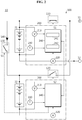
- FIG. 3 is a diagram for reference in illustrating the operation performed by the control apparatus 100 when a fault of the main battery 21 of FIG. 1 is detected.
- the MBMS 200 transmits the first diagnosis message to the SBMS 300, and stops outputting the first control signal S1.
- the first diagnosis message is a message for informing the SBMS 300 that a fault of the main battery 21 is detected.
- the first diagnosis message includes a flag indicating the type of fault detected from the main battery 21.
- the flag may include at least one of a first value, a second value and a third value.
- the first value may indicate that the main battery 21 is over-charged
- the second value may indicate that the main battery 21 is over-discharged
- the third value may indicate that the main battery 21 is over-heated.
- the SBMS 300 wakes up in response to the first diagnosis message from the MBMS 200, and outputs a second control signal S2 to the second main switch 120.
- the SBMS 300 may selectively output a third control signal S3 to the sub switch 130 according to whether the first value is included in the flag. That is, when at least one of the second value and the third value is included in the flag of the first diagnosis message, the SBMS 300 may stop outputting the third control signal S3 to induce the sub switch 130 into a turn off state, and when only the first value is included in the flag, the SBMS 300 may output the third control signal S3 to induce the sub switch 130 into a turn on state.
- the sub battery 22 supplies power to the electrical load in replacement of the main battery 21,.
- the sub switch 130 goes into a turn on state. Accordingly, it is possible to charge the sub battery 22 using electrical energy from the over-charged main battery 21.
- the MBMS 200 may stop transmitting the first diagnosis message, and output the first control signal S1.
- the MBMS 200 stops transmission of the first diagnosis message to the SBMS 300.
- the MBMS 200 may calculate the SOC of the main battery 21 by integrating the current value measured by the current sensor 220 using the ampere counting method.
- the SBMS 300 may determine that the fault of the main battery 21 is resolved when the first diagnosis message from the MBMS 200 is not received, then may stop outputting the second control signal S2.
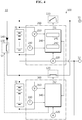
- FIG. 4 is a diagram for reference in illustrating the operation performed by the control apparatus 100 when the first controller 241 of FIG. 1 is malfunctioning.
- the second controller 242 transmits a second diagnosis message to the SBMS 300 and transmits a sleep mode inducing signal to the first controller 241 to induce the first controller 241 to a sleep state.
- the second diagnosis message is a message for informing the SBMS 300 that the MBMS 200 is malfunctioning.
- the first controller 241 stops outputting the first control signal S1.
- the SBMS 300 outputs the second control signal S2 to the second main switch 120 in response to the second diagnosis message.
- the SBMS 300 may output a third control signal S3 to the sub switch 130 in response to the second diagnosis message.
- the first main switch 110 goes into a turn off state and the second main switch 120 goes into a turn on state as shown in FIG. 4 , and thus, the sub battery 22 supplies power to the electrical load in replacement of the main battery 21.
- the SBMS 300 may compare the current measured by the current sensor 220 with the current measured by the current sensor 320.
- the sub switch 130 has a turn on state by the third control signal S3, the main battery 21 and the sub battery 22 are connected in parallel, so the current measured by the current sensor 220 and the current measured by the current sensor 320 should have the same magnitude but the opposite directions.
- the SBMS 300 may determine that a fault occurs in at least one of the current sensor 220 and the current sensor 320.
- the SBMS 300 may output a signal informing that the fault occurs in at least one of the current sensor 220 and the current sensor 320 to an external device (for example, an ECU of an electric vehicle) connected to the SBMS 300 via a communication channel.
- the communication channel may be a CAN communication network provided in the electric vehicle.
- the SBMS 300 may have a communication interface coupled to the communication channel.
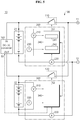
- FIG. 5 is a diagram showing an exemplary configuration of the battery system 10 according to another embodiment of the present disclosure.
- the input terminal IN of the DC-DC converter 160 is connected to the positive terminal of the main battery 21.
- the output terminal OUT of the DC-DC converter 160 is connected to the positive terminal of the sub battery 22.
- the DC-DC converter 160 In response to the third control signal S3, the DC-DC converter 160 generates an output voltage having a preset voltage level using the input voltage from the main battery 21 applied to the input terminal IN. When the output voltage generated by the DC-DC converter 160 is applied to the sub battery 22 through the output terminal OUT, the sub battery 22 is charged.
- FIGS. 6 and 7 are exemplary flowcharts showing a method for controlling the main battery 21 and the sub battery 22 according to still another embodiment of the present disclosure.
- the flowchart shown in FIG. 6 shows a method performed by the control unit 240 of the MBMS 200
- the flowchart shown in FIG. 7 shows a method performed by the control unit 340 of the SBMS 300.
- step S600 the first controller 241 determines whether a fault of the main battery 21 was detected. When a value of the step S600 is "YES”, step S610 is performed. When the value of the step S600 is "NO”, step S620 is performed.
- step S610 the first controller 241 transmits a first diagnosis message to the SBMS 300 and stops outputting the first control signal S1.
- the first diagnosis message is a message for informing the SBMS 300 that a fault of the main battery 21 is detected.
- the first diagnosis message has a flag including at least one value indicating the type of the detected fault of the main battery 21.
- the first control signal S1 is a signal for inducing the first main switch 110 into a turn on state.
- step S620 the second controller 242 determines whether the first controller 241 is malfunctioning. When a value of the step S620 is "YES”, step S630 is performed. When the value of the step S620 is "NO”, step S640 is performed.
- step S630 the second controller 242 transmits a second diagnosis message to the SBMS 300 and induces the first controller 241 to a sleep state.
- the second diagnosis message is a message for informing the SBMS 300 that the first controller 241 of the MBMS 200 is malfunctioning.
- the first controller 241 stops outputting the first control signal S1 in the sleep state.
- step S640 the first controller 241 outputs the first control signal S1 to the first main switch 110.
- step S700 the control unit 340 determines whether the first diagnosis message was received from the control unit 240.
- step S710 is performed.
- step S730 is performed.
- step S710 the control unit 340 determines whether the first value is included in the flag of the first diagnosis message.
- the first value indicates that the main battery 21 is over-charged.
- step S720 is performed.
- step S740 is performed.
- step S720 the control unit 340 outputs the second control signal S2.
- the second control signal S2 is a signal for inducing the second main switch 120 into a turn on state.
- step S730 the control unit 340 determines whether the second diagnosis message was received from the control unit 240. When a value of the step S730 is "YES”, step S740 is performed.
- step S740 the control unit 340 outputs the second control signal S2 and the third control signal S3.
- the third control signal S3 is a signal for inducing the sub switch 130 into a turn on state.
- the sub battery 22 it is possible to charge the sub battery 22 using the main battery 21 while the sub battery 22 is supplying power to the electrical load.
Landscapes
- Engineering & Computer Science (AREA)
- Power Engineering (AREA)
- Chemical Kinetics & Catalysis (AREA)
- Chemical & Material Sciences (AREA)
- Electrochemistry (AREA)
- General Chemical & Material Sciences (AREA)
- Manufacturing & Machinery (AREA)
- Physics & Mathematics (AREA)
- General Physics & Mathematics (AREA)
- Charge And Discharge Circuits For Batteries Or The Like (AREA)
- Secondary Cells (AREA)
- Direct Current Feeding And Distribution (AREA)
- Protection Of Static Devices (AREA)
- Stand-By Power Supply Arrangements (AREA)
Applications Claiming Priority (2)
| Application Number | Priority Date | Filing Date | Title |
|---|---|---|---|
| KR1020180055610A KR102390394B1 (ko) | 2018-05-15 | 2018-05-15 | 메인 배터리와 서브 배터리를 제어하기 위한 장치 및 방법 |
| PCT/KR2019/001883 WO2019221368A1 (ko) | 2018-05-15 | 2019-02-15 | 메인 배터리와 서브 배터리를 제어하기 위한 장치, 배터리 시스템 및 방법 |
Publications (3)
| Publication Number | Publication Date |
|---|---|
| EP3678272A1 true EP3678272A1 (de) | 2020-07-08 |
| EP3678272A4 EP3678272A4 (de) | 2020-07-22 |
| EP3678272B1 EP3678272B1 (de) | 2022-08-31 |
Family
ID=68540564
Family Applications (1)
| Application Number | Title | Priority Date | Filing Date |
|---|---|---|---|
| EP19803303.7A Active EP3678272B1 (de) | 2018-05-15 | 2019-02-15 | Vorrichtung, batteriesystem und verfahren zur steuerung einer hauptbatterie und einer unterbatterie |
Country Status (9)
| Country | Link |
|---|---|
| US (1) | US11054477B2 (de) |
| EP (1) | EP3678272B1 (de) |
| JP (1) | JP7130907B2 (de) |
| KR (1) | KR102390394B1 (de) |
| CN (1) | CN111052528B (de) |
| ES (1) | ES2927965T3 (de) |
| HU (1) | HUE060043T2 (de) |
| PL (1) | PL3678272T3 (de) |
| WO (1) | WO2019221368A1 (de) |
Cited By (1)
| Publication number | Priority date | Publication date | Assignee | Title |
|---|---|---|---|---|
| EP4361653A4 (de) * | 2022-02-03 | 2025-01-08 | LG Energy Solution, Ltd. | Vorrichtung und verfahren zur verwaltung einer batterie |
Families Citing this family (17)
| Publication number | Priority date | Publication date | Assignee | Title |
|---|---|---|---|---|
| EP3398818B1 (de) * | 2017-05-04 | 2022-07-06 | Volvo Car Corporation | Spannungsversorgungseinheit, batterieausgleichsverfahren |
| CN110445213B (zh) * | 2019-08-13 | 2022-05-17 | 深圳市道通智能航空技术股份有限公司 | 一种充电管理系统、方法、装置和存储介质 |
| JP7311458B2 (ja) * | 2020-04-07 | 2023-07-19 | トヨタ自動車株式会社 | バッテリー診断装置、方法、プログラム、及び車両 |
| CN111585337A (zh) * | 2020-05-27 | 2020-08-25 | 三一专用汽车有限责任公司 | 供电系统和作业车辆 |
| KR20220057368A (ko) * | 2020-10-29 | 2022-05-09 | 주식회사 엘지에너지솔루션 | 배터리 관리 장치 및 방법, 배터리 관리 시스템 |
| KR102262975B1 (ko) * | 2020-11-25 | 2021-06-09 | (주)엠알솔루텍 | 임시 소방 시설용 배터리 운용 장치 및 그 방법 |
| KR102909364B1 (ko) | 2020-12-31 | 2026-01-20 | 현대자동차 주식회사 | 배터리 제어방법 및 그 방법을 제공하는 배터리 시스템 |
| KR20230022367A (ko) * | 2021-08-06 | 2023-02-15 | 현대모비스 주식회사 | 전자식 유압 브레이크 및 이의 제어방법 |
| US11750023B2 (en) * | 2021-10-08 | 2023-09-05 | Eagle Technology, Llc | High temperature hybrid battery pack |
| US20230166724A1 (en) * | 2021-11-29 | 2023-06-01 | Rivian Ip Holdings, Llc | Supplemental battery power for moving an electric vehicle |
| CN115313572B (zh) * | 2022-08-22 | 2025-09-12 | 歌尔科技有限公司 | 可穿戴设备、充放电控制方法及存储介质 |
| KR102621445B1 (ko) * | 2023-01-02 | 2024-01-09 | 주식회사 케이에이치티 | 항공기용 배터리 관리 시스템 및 그 제어 방법 |
| KR20240111995A (ko) | 2023-01-11 | 2024-07-18 | 주식회사 엘지에너지솔루션 | 전력 공급 제어 장치 및 이의 제어 방법 |
| CN120476060A (zh) * | 2023-07-27 | 2025-08-12 | 株式会社Lg新能源 | 电池系统和电池系统的操作方法 |
| CN117162949B (zh) * | 2023-09-12 | 2025-09-23 | 上海稊米汽车科技有限公司 | 一种asil-b mcu实现asil-c汽车备用电源的方法 |
| KR20260024054A (ko) * | 2024-08-13 | 2026-02-20 | 삼성에스디아이 주식회사 | 웨이크업 기능이 포함된 배터리관리장치 및 웨이크업 방법 |
| CN121689382A (zh) * | 2026-02-11 | 2026-03-17 | 宁波德业变频技术有限公司 | 一种储能系统的补电装置和补电方法 |
Family Cites Families (38)
| Publication number | Priority date | Publication date | Assignee | Title |
|---|---|---|---|---|
| JPS60188472U (ja) | 1984-05-24 | 1985-12-13 | 中尾 一俊 | 自動車用組蓄電池 |
| JPH11341608A (ja) * | 1998-05-29 | 1999-12-10 | Honda Motor Co Ltd | 電気自動車 |
| DE10022443B4 (de) | 1999-05-10 | 2009-05-28 | Panasonic Corp., Kadoma | Notfallmeldegerät für ein Fahrzeug |
| JP3260127B2 (ja) | 1999-05-26 | 2002-02-25 | 松下電器産業株式会社 | 車載端末装置および緊急通報システム |
| JP2005080347A (ja) | 2003-08-28 | 2005-03-24 | Sanyo Electric Co Ltd | 電池の過充電保護回路、パック電池、および電池の過充電保護方法 |
| KR100824888B1 (ko) * | 2006-08-22 | 2008-04-23 | 삼성에스디아이 주식회사 | 하이브리드 배터리 팩 및 그것의 충전 방법과 방전 방법 |
| KR100824905B1 (ko) * | 2006-08-24 | 2008-04-23 | 삼성에스디아이 주식회사 | 하이브리드 배터리 및 그것의 완전 충전 용량 계산 방법 |
| WO2008096771A1 (ja) | 2007-02-08 | 2008-08-14 | Panasonic Ev Energy Co., Ltd. | 蓄電装置の異常検出装置及び方法 |
| US20090021216A1 (en) * | 2007-07-17 | 2009-01-22 | Malcolm Hills | Dual-Battery Charging And Discharging Method And Device And Portable Electronic Device Containing The Same |
| US8143855B2 (en) | 2008-02-15 | 2012-03-27 | Atieva, Inc. | Rechargeable split battery system |
| KR100995075B1 (ko) * | 2008-08-26 | 2010-11-18 | 삼성에스디아이 주식회사 | 배터리 관리 시스템 및 그 구동 방법 |
| JP5391805B2 (ja) | 2009-04-22 | 2014-01-15 | トヨタ自動車株式会社 | ハイブリッド自動車および異常判定方法 |
| EP2282494B1 (de) * | 2009-07-08 | 2018-09-05 | Lg Electronics Inc. | Mobiles Endgerät mit mehreren Batterien |
| KR101144467B1 (ko) | 2010-06-15 | 2012-05-11 | 현대자동차주식회사 | 메인 배터리의 저전압 고장 대책을 위한 전자 제어기 및 그의 구동 방법 |
| KR101174895B1 (ko) * | 2010-09-02 | 2012-08-17 | 삼성에스디아이 주식회사 | 배터리 팩, 및 이의 제어방법 |
| JP5786330B2 (ja) * | 2010-12-24 | 2015-09-30 | ソニー株式会社 | 放電制御装置及び放電制御方法 |
| JP5642018B2 (ja) | 2011-05-18 | 2014-12-17 | 本田技研工業株式会社 | 電動車両のバッテリ監視装置 |
| US9444118B2 (en) * | 2011-05-26 | 2016-09-13 | Samsung Sdi Co., Ltd. | Battery pack |
| KR20130041480A (ko) * | 2011-10-17 | 2013-04-25 | 현대자동차주식회사 | 차량의 배터리 서브팩간 전압밸런싱 방법 및 장치 |
| KR20130061814A (ko) * | 2011-12-02 | 2013-06-12 | 삼성에스디아이 주식회사 | 배터리 전압 측정회로 및 이를 구비한 전력 저장 시스템 |
| US9231440B2 (en) * | 2012-04-18 | 2016-01-05 | Samsung Sdi Co., Ltd. | Power supply apparatus and controlling method of the same |
| JP5598499B2 (ja) | 2012-06-15 | 2014-10-01 | 株式会社デンソー | 電池監視装置 |
| KR20140013250A (ko) | 2012-07-23 | 2014-02-05 | 현대모비스 주식회사 | 멀티 배터리팩을 이용한 차량용 전원 공급 장치 및 제어 방법 |
| JP6312597B2 (ja) | 2012-10-29 | 2018-04-18 | 三洋電機株式会社 | 車両用電源装置 |
| WO2014153034A1 (en) | 2013-03-14 | 2014-09-25 | Milwaukee Electric Tool Corporation | Power tool having multiple battery packs |
| JP6024537B2 (ja) | 2013-03-15 | 2016-11-16 | 株式会社デンソー | 車載電源システム |
| JP2015089293A (ja) | 2013-10-31 | 2015-05-07 | オムロンオートモーティブエレクトロニクス株式会社 | 負荷駆動装置 |
| JP2015217734A (ja) | 2014-05-15 | 2015-12-07 | 株式会社オートネットワーク技術研究所 | 自動車の電源装置 |
| US20160134160A1 (en) * | 2014-11-07 | 2016-05-12 | Schneider Electric It Corporation | Systems and methods for battery management |
| JP2016132402A (ja) | 2015-01-21 | 2016-07-25 | トヨタ自動車株式会社 | 車両 |
| JP2017028773A (ja) | 2015-07-16 | 2017-02-02 | トヨタ自動車株式会社 | 電気自動車 |
| JP6214609B2 (ja) * | 2015-10-08 | 2017-10-18 | 本田技研工業株式会社 | 駆動装置 |
| KR101945425B1 (ko) | 2015-11-27 | 2019-02-07 | 주식회사 엘지화학 | 배터리 팩 상태 병렬 모니터링 장치 |
| KR20170071949A (ko) | 2015-12-16 | 2017-06-26 | 삼성에스디아이 주식회사 | 배터리 팩 및 이를 포함하는 배터리 시스템 |
| JP6890285B2 (ja) | 2016-03-31 | 2021-06-18 | 東亜ディーケーケー株式会社 | 無停電電源装置のバッテリー診断機能付きコントローラおよびその診断方法 |
| JP6690396B2 (ja) | 2016-05-13 | 2020-04-28 | 株式会社オートネットワーク技術研究所 | リレー装置 |
| KR102610269B1 (ko) | 2016-09-05 | 2023-12-04 | 주식회사 엘지에너지솔루션 | 전력 공급 회로 및 이를 포함하는 배터리 팩 |
| KR20180055610A (ko) | 2016-11-17 | 2018-05-25 | 변창훈 | 장갑 형태의 발열 손난로 |
-
2018
- 2018-05-15 KR KR1020180055610A patent/KR102390394B1/ko active Active
-
2019
- 2019-02-15 US US16/634,740 patent/US11054477B2/en active Active
- 2019-02-15 PL PL19803303.7T patent/PL3678272T3/pl unknown
- 2019-02-15 CN CN201980004186.9A patent/CN111052528B/zh active Active
- 2019-02-15 EP EP19803303.7A patent/EP3678272B1/de active Active
- 2019-02-15 JP JP2020506212A patent/JP7130907B2/ja active Active
- 2019-02-15 ES ES19803303T patent/ES2927965T3/es active Active
- 2019-02-15 HU HUE19803303A patent/HUE060043T2/hu unknown
- 2019-02-15 WO PCT/KR2019/001883 patent/WO2019221368A1/ko not_active Ceased
Cited By (1)
| Publication number | Priority date | Publication date | Assignee | Title |
|---|---|---|---|---|
| EP4361653A4 (de) * | 2022-02-03 | 2025-01-08 | LG Energy Solution, Ltd. | Vorrichtung und verfahren zur verwaltung einer batterie |
Also Published As
| Publication number | Publication date |
|---|---|
| HUE060043T2 (hu) | 2023-01-28 |
| JP7130907B2 (ja) | 2022-09-06 |
| KR20190130901A (ko) | 2019-11-25 |
| WO2019221368A1 (ko) | 2019-11-21 |
| PL3678272T3 (pl) | 2022-11-07 |
| US20200209321A1 (en) | 2020-07-02 |
| US11054477B2 (en) | 2021-07-06 |
| CN111052528B (zh) | 2023-08-11 |
| KR102390394B1 (ko) | 2022-04-22 |
| EP3678272B1 (de) | 2022-08-31 |
| ES2927965T3 (es) | 2022-11-14 |
| JP2020530751A (ja) | 2020-10-22 |
| EP3678272A4 (de) | 2020-07-22 |
| CN111052528A (zh) | 2020-04-21 |
Similar Documents
| Publication | Publication Date | Title |
|---|---|---|
| US11054477B2 (en) | Apparatus, battery system and method for controlling main battery and sub battery | |
| EP3687027B1 (de) | Batteriesteuerungsvorrichtung und energiespeichersystem damit | |
| AU2019262442B2 (en) | Battery management apparatus, battery management method, and energy storage system including the battery management apparatus | |
| EP2523248B1 (de) | Batterieüberwachungsvorrichtung und -verfahren | |
| EP3790151B1 (de) | Ausgleichsvorrichtung und batteriemanagementsystem sowie batteriepackung mit demselben | |
| US9187000B2 (en) | Battery pack and electrically driven automobile | |
| KR101921641B1 (ko) | 배터리 제어 장치 및 방법 | |
| EP3588660B1 (de) | Batteriepack und stromversorgungssystem damit | |
| US11114703B2 (en) | Battery pack | |
| KR101596488B1 (ko) | 오작동 방지 알고리즘을 포함하는 배터리 관리 시스템 및 방법 | |
| US12483061B2 (en) | Battery pack |
Legal Events
| Date | Code | Title | Description |
|---|---|---|---|
| STAA | Information on the status of an ep patent application or granted ep patent |
Free format text: STATUS: THE INTERNATIONAL PUBLICATION HAS BEEN MADE |
|
| PUAI | Public reference made under article 153(3) epc to a published international application that has entered the european phase |
Free format text: ORIGINAL CODE: 0009012 |
|
| STAA | Information on the status of an ep patent application or granted ep patent |
Free format text: STATUS: REQUEST FOR EXAMINATION WAS MADE |
|
| 17P | Request for examination filed |
Effective date: 20200330 |
|
| AK | Designated contracting states |
Kind code of ref document: A1 Designated state(s): AL AT BE BG CH CY CZ DE DK EE ES FI FR GB GR HR HU IE IS IT LI LT LU LV MC MK MT NL NO PL PT RO RS SE SI SK SM TR |
|
| AX | Request for extension of the european patent |
Extension state: BA ME |
|
| A4 | Supplementary search report drawn up and despatched |
Effective date: 20200618 |
|
| RIC1 | Information provided on ipc code assigned before grant |
Ipc: H02J 13/00 20060101ALI20200612BHEP Ipc: H02J 1/10 20060101AFI20200612BHEP Ipc: H02J 7/34 20060101ALI20200612BHEP Ipc: H02J 9/06 20060101ALI20200612BHEP Ipc: H02J 7/00 20060101ALI20200612BHEP |
|
| DAV | Request for validation of the european patent (deleted) | ||
| DAX | Request for extension of the european patent (deleted) | ||
| RAP1 | Party data changed (applicant data changed or rights of an application transferred) |
Owner name: LG ENERGY SOLUTION LTD. |
|
| RAP3 | Party data changed (applicant data changed or rights of an application transferred) |
Owner name: LG ENERGY SOLUTION, LTD. |
|
| GRAP | Despatch of communication of intention to grant a patent |
Free format text: ORIGINAL CODE: EPIDOSNIGR1 |
|
| STAA | Information on the status of an ep patent application or granted ep patent |
Free format text: STATUS: GRANT OF PATENT IS INTENDED |
|
| INTG | Intention to grant announced |
Effective date: 20220516 |
|
| GRAS | Grant fee paid |
Free format text: ORIGINAL CODE: EPIDOSNIGR3 |
|
| GRAA | (expected) grant |
Free format text: ORIGINAL CODE: 0009210 |
|
| STAA | Information on the status of an ep patent application or granted ep patent |
Free format text: STATUS: THE PATENT HAS BEEN GRANTED |
|
| AK | Designated contracting states |
Kind code of ref document: B1 Designated state(s): AL AT BE BG CH CY CZ DE DK EE ES FI FR GB GR HR HU IE IS IT LI LT LU LV MC MK MT NL NO PL PT RO RS SE SI SK SM TR |
|
| REG | Reference to a national code |
Ref country code: CH Ref legal event code: EP Ref country code: GB Ref legal event code: FG4D |
|
| REG | Reference to a national code |
Ref country code: AT Ref legal event code: REF Ref document number: 1516004 Country of ref document: AT Kind code of ref document: T Effective date: 20220915 |
|
| REG | Reference to a national code |
Ref country code: DE Ref legal event code: R096 Ref document number: 602019019068 Country of ref document: DE |
|
| REG | Reference to a national code |
Ref country code: IE Ref legal event code: FG4D |
|
| REG | Reference to a national code |
Ref country code: SE Ref legal event code: TRGR |
|
| REG | Reference to a national code |
Ref country code: ES Ref legal event code: FG2A Ref document number: 2927965 Country of ref document: ES Kind code of ref document: T3 Effective date: 20221114 |
|
| REG | Reference to a national code |
Ref country code: LT Ref legal event code: MG9D |
|
| REG | Reference to a national code |
Ref country code: NL Ref legal event code: MP Effective date: 20220831 |
|
| REG | Reference to a national code |
Ref country code: HU Ref legal event code: AG4A Ref document number: E060043 Country of ref document: HU |
|
| PG25 | Lapsed in a contracting state [announced via postgrant information from national office to epo] |
Ref country code: RS Free format text: LAPSE BECAUSE OF FAILURE TO SUBMIT A TRANSLATION OF THE DESCRIPTION OR TO PAY THE FEE WITHIN THE PRESCRIBED TIME-LIMIT Effective date: 20220831 Ref country code: NO Free format text: LAPSE BECAUSE OF FAILURE TO SUBMIT A TRANSLATION OF THE DESCRIPTION OR TO PAY THE FEE WITHIN THE PRESCRIBED TIME-LIMIT Effective date: 20221130 Ref country code: LV Free format text: LAPSE BECAUSE OF FAILURE TO SUBMIT A TRANSLATION OF THE DESCRIPTION OR TO PAY THE FEE WITHIN THE PRESCRIBED TIME-LIMIT Effective date: 20220831 Ref country code: LT Free format text: LAPSE BECAUSE OF FAILURE TO SUBMIT A TRANSLATION OF THE DESCRIPTION OR TO PAY THE FEE WITHIN THE PRESCRIBED TIME-LIMIT Effective date: 20220831 Ref country code: FI Free format text: LAPSE BECAUSE OF FAILURE TO SUBMIT A TRANSLATION OF THE DESCRIPTION OR TO PAY THE FEE WITHIN THE PRESCRIBED TIME-LIMIT Effective date: 20220831 |
|
| REG | Reference to a national code |
Ref country code: AT Ref legal event code: MK05 Ref document number: 1516004 Country of ref document: AT Kind code of ref document: T Effective date: 20220831 |
|
| PG25 | Lapsed in a contracting state [announced via postgrant information from national office to epo] |
Ref country code: IS Free format text: LAPSE BECAUSE OF FAILURE TO SUBMIT A TRANSLATION OF THE DESCRIPTION OR TO PAY THE FEE WITHIN THE PRESCRIBED TIME-LIMIT Effective date: 20221231 Ref country code: HR Free format text: LAPSE BECAUSE OF FAILURE TO SUBMIT A TRANSLATION OF THE DESCRIPTION OR TO PAY THE FEE WITHIN THE PRESCRIBED TIME-LIMIT Effective date: 20220831 Ref country code: GR Free format text: LAPSE BECAUSE OF FAILURE TO SUBMIT A TRANSLATION OF THE DESCRIPTION OR TO PAY THE FEE WITHIN THE PRESCRIBED TIME-LIMIT Effective date: 20221201 |
|
| PG25 | Lapsed in a contracting state [announced via postgrant information from national office to epo] |
Ref country code: SM Free format text: LAPSE BECAUSE OF FAILURE TO SUBMIT A TRANSLATION OF THE DESCRIPTION OR TO PAY THE FEE WITHIN THE PRESCRIBED TIME-LIMIT Effective date: 20220831 Ref country code: RO Free format text: LAPSE BECAUSE OF FAILURE TO SUBMIT A TRANSLATION OF THE DESCRIPTION OR TO PAY THE FEE WITHIN THE PRESCRIBED TIME-LIMIT Effective date: 20220831 Ref country code: PT Free format text: LAPSE BECAUSE OF FAILURE TO SUBMIT A TRANSLATION OF THE DESCRIPTION OR TO PAY THE FEE WITHIN THE PRESCRIBED TIME-LIMIT Effective date: 20230102 Ref country code: DK Free format text: LAPSE BECAUSE OF FAILURE TO SUBMIT A TRANSLATION OF THE DESCRIPTION OR TO PAY THE FEE WITHIN THE PRESCRIBED TIME-LIMIT Effective date: 20220831 Ref country code: CZ Free format text: LAPSE BECAUSE OF FAILURE TO SUBMIT A TRANSLATION OF THE DESCRIPTION OR TO PAY THE FEE WITHIN THE PRESCRIBED TIME-LIMIT Effective date: 20220831 Ref country code: AT Free format text: LAPSE BECAUSE OF FAILURE TO SUBMIT A TRANSLATION OF THE DESCRIPTION OR TO PAY THE FEE WITHIN THE PRESCRIBED TIME-LIMIT Effective date: 20220831 |
|
| PG25 | Lapsed in a contracting state [announced via postgrant information from national office to epo] |
Ref country code: SK Free format text: LAPSE BECAUSE OF FAILURE TO SUBMIT A TRANSLATION OF THE DESCRIPTION OR TO PAY THE FEE WITHIN THE PRESCRIBED TIME-LIMIT Effective date: 20220831 Ref country code: EE Free format text: LAPSE BECAUSE OF FAILURE TO SUBMIT A TRANSLATION OF THE DESCRIPTION OR TO PAY THE FEE WITHIN THE PRESCRIBED TIME-LIMIT Effective date: 20220831 |
|
| REG | Reference to a national code |
Ref country code: DE Ref legal event code: R097 Ref document number: 602019019068 Country of ref document: DE |
|
| P01 | Opt-out of the competence of the unified patent court (upc) registered |
Effective date: 20230408 |
|
| PG25 | Lapsed in a contracting state [announced via postgrant information from national office to epo] |
Ref country code: NL Free format text: LAPSE BECAUSE OF FAILURE TO SUBMIT A TRANSLATION OF THE DESCRIPTION OR TO PAY THE FEE WITHIN THE PRESCRIBED TIME-LIMIT Effective date: 20220831 Ref country code: AL Free format text: LAPSE BECAUSE OF FAILURE TO SUBMIT A TRANSLATION OF THE DESCRIPTION OR TO PAY THE FEE WITHIN THE PRESCRIBED TIME-LIMIT Effective date: 20220831 |
|
| PLBE | No opposition filed within time limit |
Free format text: ORIGINAL CODE: 0009261 |
|
| STAA | Information on the status of an ep patent application or granted ep patent |
Free format text: STATUS: NO OPPOSITION FILED WITHIN TIME LIMIT |
|
| 26N | No opposition filed |
Effective date: 20230601 |
|
| PG25 | Lapsed in a contracting state [announced via postgrant information from national office to epo] |
Ref country code: SI Free format text: LAPSE BECAUSE OF FAILURE TO SUBMIT A TRANSLATION OF THE DESCRIPTION OR TO PAY THE FEE WITHIN THE PRESCRIBED TIME-LIMIT Effective date: 20220831 |
|
| PG25 | Lapsed in a contracting state [announced via postgrant information from national office to epo] |
Ref country code: MC Free format text: LAPSE BECAUSE OF FAILURE TO SUBMIT A TRANSLATION OF THE DESCRIPTION OR TO PAY THE FEE WITHIN THE PRESCRIBED TIME-LIMIT Effective date: 20220831 |
|
| REG | Reference to a national code |
Ref country code: CH Ref legal event code: PL |
|
| REG | Reference to a national code |
Ref country code: BE Ref legal event code: MM Effective date: 20230228 |
|
| PG25 | Lapsed in a contracting state [announced via postgrant information from national office to epo] |
Ref country code: LU Free format text: LAPSE BECAUSE OF NON-PAYMENT OF DUE FEES Effective date: 20230215 Ref country code: LI Free format text: LAPSE BECAUSE OF NON-PAYMENT OF DUE FEES Effective date: 20230228 Ref country code: CH Free format text: LAPSE BECAUSE OF NON-PAYMENT OF DUE FEES Effective date: 20230228 |
|
| REG | Reference to a national code |
Ref country code: IE Ref legal event code: MM4A |
|
| PG25 | Lapsed in a contracting state [announced via postgrant information from national office to epo] |
Ref country code: IE Free format text: LAPSE BECAUSE OF NON-PAYMENT OF DUE FEES Effective date: 20230215 |
|
| PG25 | Lapsed in a contracting state [announced via postgrant information from national office to epo] |
Ref country code: BE Free format text: LAPSE BECAUSE OF NON-PAYMENT OF DUE FEES Effective date: 20230228 |
|
| PG25 | Lapsed in a contracting state [announced via postgrant information from national office to epo] |
Ref country code: IT Free format text: LAPSE BECAUSE OF FAILURE TO SUBMIT A TRANSLATION OF THE DESCRIPTION OR TO PAY THE FEE WITHIN THE PRESCRIBED TIME-LIMIT Effective date: 20220831 |
|
| PG25 | Lapsed in a contracting state [announced via postgrant information from national office to epo] |
Ref country code: BG Free format text: LAPSE BECAUSE OF FAILURE TO SUBMIT A TRANSLATION OF THE DESCRIPTION OR TO PAY THE FEE WITHIN THE PRESCRIBED TIME-LIMIT Effective date: 20220831 |
|
| PG25 | Lapsed in a contracting state [announced via postgrant information from national office to epo] |
Ref country code: BG Free format text: LAPSE BECAUSE OF FAILURE TO SUBMIT A TRANSLATION OF THE DESCRIPTION OR TO PAY THE FEE WITHIN THE PRESCRIBED TIME-LIMIT Effective date: 20220831 |
|
| PG25 | Lapsed in a contracting state [announced via postgrant information from national office to epo] |
Ref country code: CY Free format text: LAPSE BECAUSE OF FAILURE TO SUBMIT A TRANSLATION OF THE DESCRIPTION OR TO PAY THE FEE WITHIN THE PRESCRIBED TIME-LIMIT; INVALID AB INITIO Effective date: 20190215 |
|
| PG25 | Lapsed in a contracting state [announced via postgrant information from national office to epo] |
Ref country code: TR Free format text: LAPSE BECAUSE OF FAILURE TO SUBMIT A TRANSLATION OF THE DESCRIPTION OR TO PAY THE FEE WITHIN THE PRESCRIBED TIME-LIMIT Effective date: 20220831 |
|
| PGFP | Annual fee paid to national office [announced via postgrant information from national office to epo] |
Ref country code: HU Payment date: 20260227 Year of fee payment: 8 |
|
| PGFP | Annual fee paid to national office [announced via postgrant information from national office to epo] |
Ref country code: SE Payment date: 20260121 Year of fee payment: 8 |
|
| PGFP | Annual fee paid to national office [announced via postgrant information from national office to epo] |
Ref country code: GB Payment date: 20260122 Year of fee payment: 8 |
|
| PGFP | Annual fee paid to national office [announced via postgrant information from national office to epo] |
Ref country code: ES Payment date: 20260324 Year of fee payment: 8 |
|
| PGFP | Annual fee paid to national office [announced via postgrant information from national office to epo] |
Ref country code: DE Payment date: 20260120 Year of fee payment: 8 |
|
| PGFP | Annual fee paid to national office [announced via postgrant information from national office to epo] |
Ref country code: FR Payment date: 20260121 Year of fee payment: 8 |
|
| PGFP | Annual fee paid to national office [announced via postgrant information from national office to epo] |
Ref country code: PL Payment date: 20260120 Year of fee payment: 8 |