EP3678287B1 - Dispositif et procédé de conversion de courant - Google Patents
Dispositif et procédé de conversion de courant Download PDFInfo
- Publication number
- EP3678287B1 EP3678287B1 EP18851051.5A EP18851051A EP3678287B1 EP 3678287 B1 EP3678287 B1 EP 3678287B1 EP 18851051 A EP18851051 A EP 18851051A EP 3678287 B1 EP3678287 B1 EP 3678287B1
- Authority
- EP
- European Patent Office
- Prior art keywords
- conductor
- gate
- terminal
- gate driver
- switching module
- Prior art date
- Legal status (The legal status is an assumption and is not a legal conclusion. Google has not performed a legal analysis and makes no representation as to the accuracy of the status listed.)
- Active
Links
Images


Classifications
-
- H—ELECTRICITY
- H03—ELECTRONIC CIRCUITRY
- H03K—PULSE TECHNIQUE
- H03K17/00—Electronic switching or gating, i.e. not by contact-making and –breaking
- H03K17/16—Modifications for eliminating interference voltages or currents
- H03K17/161—Modifications for eliminating interference voltages or currents in field-effect transistor switches
- H03K17/162—Modifications for eliminating interference voltages or currents in field-effect transistor switches without feedback from the output circuit to the control circuit
-
- H—ELECTRICITY
- H02—GENERATION; CONVERSION OR DISTRIBUTION OF ELECTRIC POWER
- H02M—APPARATUS FOR CONVERSION BETWEEN AC AND AC, BETWEEN AC AND DC, OR BETWEEN DC AND DC, AND FOR USE WITH MAINS OR SIMILAR POWER SUPPLY SYSTEMS; CONVERSION OF DC OR AC INPUT POWER INTO SURGE OUTPUT POWER; CONTROL OR REGULATION THEREOF
- H02M7/00—Conversion of AC power input into DC power output; Conversion of DC power input into AC power output
- H02M7/003—Constructional details, e.g. physical layout, assembly, wiring or busbar connections
-
- H—ELECTRICITY
- H03—ELECTRONIC CIRCUITRY
- H03K—PULSE TECHNIQUE
- H03K17/00—Electronic switching or gating, i.e. not by contact-making and –breaking
- H03K17/08—Modifications for protecting switching circuit against overcurrent or overvoltage
- H03K17/081—Modifications for protecting switching circuit against overcurrent or overvoltage without feedback from the output circuit to the control circuit
- H03K17/0812—Modifications for protecting switching circuit against overcurrent or overvoltage without feedback from the output circuit to the control circuit by measures taken in the control circuit
- H03K17/08122—Modifications for protecting switching circuit against overcurrent or overvoltage without feedback from the output circuit to the control circuit by measures taken in the control circuit in field-effect transistor switches
-
- H—ELECTRICITY
- H03—ELECTRONIC CIRCUITRY
- H03K—PULSE TECHNIQUE
- H03K17/00—Electronic switching or gating, i.e. not by contact-making and –breaking
- H03K17/08—Modifications for protecting switching circuit against overcurrent or overvoltage
- H03K17/081—Modifications for protecting switching circuit against overcurrent or overvoltage without feedback from the output circuit to the control circuit
- H03K17/0812—Modifications for protecting switching circuit against overcurrent or overvoltage without feedback from the output circuit to the control circuit by measures taken in the control circuit
- H03K17/08128—Modifications for protecting switching circuit against overcurrent or overvoltage without feedback from the output circuit to the control circuit by measures taken in the control circuit in composite switches
-
- H—ELECTRICITY
- H03—ELECTRONIC CIRCUITRY
- H03K—PULSE TECHNIQUE
- H03K17/00—Electronic switching or gating, i.e. not by contact-making and –breaking
- H03K17/16—Modifications for eliminating interference voltages or currents
- H03K17/168—Modifications for eliminating interference voltages or currents in composite switches
-
- H—ELECTRICITY
- H03—ELECTRONIC CIRCUITRY
- H03K—PULSE TECHNIQUE
- H03K17/00—Electronic switching or gating, i.e. not by contact-making and –breaking
- H03K17/51—Electronic switching or gating, i.e. not by contact-making and –breaking characterised by the components used
- H03K17/56—Electronic switching or gating, i.e. not by contact-making and –breaking characterised by the components used by the use, as active elements, of semiconductor devices
- H03K17/687—Electronic switching or gating, i.e. not by contact-making and –breaking characterised by the components used by the use, as active elements, of semiconductor devices the devices being field-effect transistors
-
- H—ELECTRICITY
- H02—GENERATION; CONVERSION OR DISTRIBUTION OF ELECTRIC POWER
- H02M—APPARATUS FOR CONVERSION BETWEEN AC AND AC, BETWEEN AC AND DC, OR BETWEEN DC AND DC, AND FOR USE WITH MAINS OR SIMILAR POWER SUPPLY SYSTEMS; CONVERSION OF DC OR AC INPUT POWER INTO SURGE OUTPUT POWER; CONTROL OR REGULATION THEREOF
- H02M1/00—Details of apparatus for conversion
- H02M1/08—Circuits specially adapted for the generation of control voltages for semiconductor devices incorporated in static converters
Definitions
- the present invention relates to a power conversion device and a power conversion method, and is particularly suitable for being applied to a large-power power conversion device used for a railroad vehicle driven by a motor, a steel rolling mill, a wind power generator, and the like.
- a power conversion device that converts large power between DC and AC for a railroad vehicle, a steel rolling mill, a wind power generator, and the like uses, as a switching element for power conversion, a power semiconductor element that can control a large current of several hundred amperes or larger under a high voltage exceeding 1 kV.
- a power conversion device using an IGBT (Insulated Gate Bipolar Transistor) as a switching element has been known (Patent Literature 1).
- the IGBT is a composite bipolar element in which an input part has a MOSFET structure, an output part has a bipolar structure, and both of a low saturated voltage and a relatively-fast switching characteristic are realized.
- the IGBT includes two main terminals (a collector terminal and an emitter terminal) that energize a main power supply and a gate terminal as a control terminal that controls a current, and a gate drive circuit for controlling a gate voltage is connected to the gate terminal. When the gate drive circuit changes a gate voltage, a main current flowing between the collector terminal and the emitter terminal is controlled.
- Nonpatent Literature 1 an element of a wide band gap semiconductor such as SiC (silicon carbide), GaN (gallium nitride), or diamond instead of silicon has been applied to the power conversion device (Nonpatent Literature 1).
- the dielectric breakdown field intensity of the wide band gap semiconductor is several times as large as silicon (about 10 times in the case of SiC and GaN and about 30 times in the case of diamond), the impurity concentration of a chip can be increased, and further the thickness of the chip can be configured thinner. Accordingly, conductive resistance at the time of current energization is reduced, and a conduction loss can be decreased.
- a power MOSFET having a faster switching characteristic and a unipolar structure instead of the IGBT having a bipolar structure can be used as the switching element.
- a silicon semiconductor can withstand up to about 200°C
- the wide band gap semiconductor can withstand higher temperatures exceeding 200°C.
- the power converter can be downsized by simplifying a cooler of the power converter.
- Patent Literature 1 Japanese Unexamined Patent Application Publication No. 2015-198545 JP H10-257754 describes an inductance 2, a first switching element 3 and a control electrode 5 being connected in series between the control electrode and the cathode of a current controlled switching element 1, while a second switching element 4 is connected in parallel between the control electrode and the cathode of the element 1 and a diode 6 is connected in parallel between the joint of the inductance 2 and the first switching element 3 and the joint of the control electrode 5 and the diode 6.
- Current flowing through the inductance 2 is substantially kept constant by turning the first switching element 3 on/off while turning the second switching element 4 is turned on and it is commutated to the control electrode of the element 1 by turning the second switching element 4 off.
- Nonpatent Literature 1 Gate-Driver with Full Protection for SiC-MOSFET Modules
- VDE Conference Publication Karsten Fink and Andreas Volke, Power Integrations GmbH, Germany, Winson Wei, Power Integrations, China, and Eugen Wiesner and Eckhard ThaI, Mitsubishi Electric Europe B.V., Germany, Date of Conference: 28-30 June 2016 .
- a gate drive circuit is connected to a switching element through a wiring (gate wiring), and the wiring length is about 50 cm to 1 m.
- the wiring length is made long to prevent malfunction of the gate drive circuit due to electromagnetic noise at the time of switching performed by a power semiconductor element using a high voltage and a large current.
- the fluctuation of the gate voltage due to the feedback capacitance is also increased in the wide band gap semiconductor. Even if the impurity concentration of a MOSFET using the wide band gap semiconductor is increased to reduce the resistance and the thickness thereof is reduced, the feedback capacitance is reversely increased.
- an object of the present invention is to propose a power conversion device and a power conversion method in which when a gate drive circuit is connected separately from a switching element and the temperature of the switching element becomes high due to a switching operation, malfunction of the switching element is prevented by suppressing fluctuation of a gate voltage to improve the reliability.
- the present invention provides a power conversion device and a power conversion method according to the independent claims.
- the present invention it is possible to propose a power conversion device and a power conversion method in which when a gate drive circuit is connected separately from a switching element and the temperature of the switching element becomes high due to a switching operation, malfunction of the switching element is prevented by suppressing fluctuation of a gate voltage to improve the reliability.
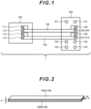
- FIG. 1 is a block diagram of a power conversion device according to a first embodiment, and is a block diagram of a switching system of a power conversion device in detail.
- a power conversion device 1 includes a switching module 300 having a switching element, a gate drive circuit (gate driver) 320, and gate wiring bodies 108 as wirings through which these are electrically connected to each other.
- gate driver gate drive circuit
- the gate wiring bodies will be abbreviated as wirings or gate wirings in some cases.
- the gate wiring bodies 108 are configured using a plurality of flat plate-like conductors as preferred embodiments as will be described later ( Fig. 2 ), and thus will be also described as gate wiring bars 108.
- the switching element may be an IGBT.
- the switching module 300 will be described as an IGBT module 300.
- the IBGT may be a silicon semiconductor or a wide band gap semiconductor.
- the switching element may be a power MOSFET (Metal-Oxide-Semiconductor Field-Effect Transistor) configured using a wide band gap semiconductor.
- the gate driver 320 includes an upper arm source auxiliary terminal 111, an upper arm gate terminal 112, a lower arm source auxiliary terminal 113, and a lower arm gate terminal 114.
- the IGBT module 300 includes AC main terminals 101, DC P-terminals 102, DC N-terminals 103, an upper arm source auxiliary terminal 104, an upper arm gate terminal 303 (corresponding to an upper arm gate terminal 105 to be described later), a lower arm source auxiliary terminal 106, and a lower arm gate terminal 313 (corresponding to a lower arm gate terminal 107 to be described later).
- the upper arm gate terminal 112 is connected to the upper arm gate terminal 303 through the gate wiring bar 108, and the upper arm source auxiliary terminal 111 is provided near the upper arm gate terminal 112.
- the upper arm source auxiliary terminal 104 is provided near the upper arm gate terminal 303.
- the lower arm gate terminal 114 is connected to the lower arm gate terminal 313 through the gate wiring bar 108, and the lower arm source auxiliary terminal 113 is provided near the lower arm gate terminal 114.
- the lower arm source auxiliary terminal 106 is provided near the lower arm gate terminal 313.
- two upper arm and lower arm DC P-terminals 102 and two upper arm and lower arm DC N-terminals 103 are provided, and two upper arm and lower arm AC main terminals 101 are provided.
- the gate wiring body 108 may be configured in such a mode that inductance between the IGBT module 300 and the gate driver 320 can be reduced in a range of one severalth to one several tenth as compared to wirings configured using conventional electric wires, and a plurality of conductors may oppose each other in a planar manner with a minute interval therebetween as a main mode. At least, a pair of flat plate-like conductors that are parallel to each other oppose each other. In other words, the "flat plate-like" may be changed to "rectangular", "planar", or "layered".
- the gate wiring body 108 can be manufactured in such a manner that a plurality of conductors is laminated so as to sandwich a thin film-like insulator therebetween to join the insulator and the conductors together in a laminated manner.
- a plurality of conductors oppose each other in a planar manner may be coaxially or concentrically combined with each other in addition to the flat plate-like conductors. Namely, an area where a conductor 108A opposes a conductor 108B is large, and an interval between the conductor 108A and the conductor 108B is set as small as possible to reduce inductance.
- the conductor may be made of material having conductivity such as copper or aluminum, or material such as iron or stainless material.
- the plane may be a flat plane or a curved plane.
- Fig. 2 is a perspective view of the gate wiring bar 108 shown in Fig. 1 .
- the gate wiring bar 108 is configured in such a manner that two flat plates 108A and 108B each having a width W oppose each other with an interval d therebetween.
- the inductance of the gate wiring bar 108 is set in accordance with configurations or arrangement of the two flat plates 108A and 108B opposing each other. As the flat plates 108A and 108B each having a wider area are arranged nearer each other, the inductance of the gate wiring bar 108 is reduced.
- Equation (1) For the width W and the interval d of the two flat plates 108A and 108B, a relation shown in the following Equation (1) is established. [Equation 1] W / d ⁇ 5
- the present invention may employ an integrally-molded laminate bus bar structure in which the two flat plates 108A and 108B are laminated while sandwiching a sheet-like insulating material therebetween and the entirety is laminated after being coated with an insulating material.
- the wiring length of the gate wiring bar 108 is about 50 cm to 1 m. While the maximum inductance of wirings configured using a pair of electric wires is 1 ⁇ H, the inductance of the gate wiring bar 108 is reduced to 200 nH or smaller.
- the inductance in the case where the gate driver 320 and the IGBT module 300 are connected to each other through an electric wire under the conditions where the interval between the gate driver 320 and the IGBT module 300 is 50 cm and the size of the gate wiring bar 108 is set as described above is compared to the inductance in the case where the gate driver 320 and the IGBT module 300 are connected to each other through the gate wiring bar 108, the former is about 350 nH whereas the latter is reduced to about 30 nH.
- Fig. 3 is a circuit diagram of the IGBT module 300 and the gate driver 320 as an electrical configuration example.
- the IGBT module 300 is a so-called 2in1-type IGBT module.
- Two IGBTs 305 and 315 as switching elements are included in one package, and are connected in series at a connection point with an AC input/output terminal 325 connected to the above-described AC main terminal 101.
- the lower arm has the same configuration as the upper arm, and thus the description of the upper arm is mainly substituted for that of the lower arm except for a case in which the lower arm needs to be particularly referred to.
- the gate driver 320 In the gate driver 320, the upper arm source auxiliary terminal 111, the upper arm gate terminal 112, the lower arm source auxiliary terminal 113, and the lower arm gate terminal 114 described in Fig. 1 are omitted.
- An upper arm free-wheel diode 306 is connected to the IGBT 305 in antiparallel. In the case where a current flows in the upper arm free-wheel diode 306 in the direction opposite to the IGBT 305, the current is recirculated.
- a free-wheel diode 109 can be configured using, for example, a MOSFET-incorporated body diode.
- On/off of the IGBT 305 is controlled in accordance with a voltage applied to a gate terminal 303 (corresponding to an upper arm gate main terminal to be described later) and an emitter auxiliary terminal 304.
- a voltage applied to a gate terminal 303 corresponding to an upper arm gate main terminal to be described later
- an emitter auxiliary terminal 304 When a positive voltage is applied to the gate terminal 303 in the IGBT 305, a current flows from an upper arm collector 330 towards an upper arm emitter 331.
- the gate driver 320 generates a voltage applied to the gate terminal 303 of the IGBT 305.
- the gate driver 320 generates a gate voltage on the basis of a driving command from a gate command unit (gate command module) 322 that entirely controls the inverter system, and outputs the same to the gate terminal 303 of the IGBT 305.
- the gate command unit 322 may be configured using software and/or hardware.
- the gate driver 320 and the gate command unit 322 are coupled to each other through a photo coupler 324, and the IGBT 305 and the like to which a high voltage is applied are insulated from the gate command unit 322.
- a power supply for driving the gate driver 320 is supplied from a gate power supply 321 through a gate power supply transformer 323 that is an insulating transformer.
- the gate driver 320 and the IGBT module 300 are connected to each other through the two flat plates 108A and 108B configuring the above-described gate wiring bar 108 in each case of the upper arm and the lower arm. While a parasitic capacitance 307 referred to as “feedback capacitance” is present between the upper arm collector main terminal 301 connected to the DC P-terminal 102 and the upper arm gate main terminal 303 (corresponding to the gate terminal), and a parasitic capacitance 308 referred to as "input capacitance” is present between the upper arm gate main terminal 303 and the upper arm emitter 331.
- FIG. 4(A) to Fig. 4(C) shows an example of each waveform at the time of reverse recovery of the upper arm free-wheel diode 306 connected to the IGBT 305 in antiparallel.
- the one-dot chain line shows an example of an anode current Ia of the upper arm free-wheel diode 306, and the two-dot chain line shows an example of a voltage Vac between the anode and the cathode of the upper arm free-wheel diode 306.
- Fig. 4(B) shows an example of a gate current Ig flowing in the upper arm gate main terminal 303 of the IGBT 305
- Fig. 4(C) shows an example of a gate voltage Vg in the upper arm gate main terminal 303 of the IGBT 305.
- the anode current Ia of the upper arm free-wheel diode 306 flowed in the forward direction until Time t1.
- a voltage Vac between the anode and the cathode fluctuates in the course of a turn of the flow thereafter as shown by the two-dot chain line in Fig. 4(A) .
- a turn of the flow of the anode current Ia of the upper arm free-wheel diode 306 starts at Time t1.
- Fig. 5 shows an example of a state in which a parasitic current Igres flows between the upper arm collector main terminal 301 and the upper arm gate main terminal 303 in the IGBT 305.
- the parasitic capacitance 307 referred to as "feedback capacitance" (the value of which is described as Cres) is present between the upper arm collector main terminal 301 and the upper arm gate main terminal 303 in the IGBT 305 as described above, and thus the parasitic current Igres shown in the following Equation (2) flows from the upper arm collector main terminal 301 to the upper arm gate main terminal 303 in accordance with the change of the voltage.
- Igres Cres ⁇ dVce / dt
- the parasitic current Igres separately flows to the above-described input capacitance (the value of which is described as Cies) of the IGBT 305 and the gate driver 320. If the impedance of the output circuit and the gate wiring of the gate driver 320 is small, the parasitic current Igres fully flows to the gate driver 320 and does not charge the parasitic capacitance 308 referred to as "input capacitance". Thus, the gate voltage of the gate wiring does not fluctuate. It should be noted that the gate wiring described herein corresponds to the gate wiring bar 108 in the case of the embodiment.
- the parasitic current Igres flows to and charges the parasitic capacitance 308 referred to as "input capacitance".
- the gate voltage of the upper arm gate main terminal 303 of the IGBT 305 is increased as shown in Fig. 4(C) .
- the IGBT 305 is erroneously turned on if the gate voltage Vg of the upper arm gate main terminal 303 exceeds a threshold value voltage Vt of the IGBT 305.
- the inductance 309 of the gate wiring is dependent on the length of the gate wiring. As the length of the gate wiring becomes long, the inductance 309 is increased, and the possibility of erroneously turning on the IGBT 305 is enhanced.
- At least a part of the gate wirings of the IGBT 305 is configured using the gate wiring bar 108 including the pair of flat plates 108A and 108B that oppose and are adjacent to each other in the embodiment as described above.
- the parasitic current Igres flows to the gate driver 320, and does not charge the parasitic capacitance 308 referred to as "input capacitance".
- the gate voltage of the gate wiring does not fluctuate.
- the IGBT 305 is prevented from being erroneously turned on.
- the gate driver 320 is arranged apart from a position that is not affected by rise in temperature, the gate voltage of the IGBT 305 can be prevented from fluctuating by employing the gate wiring bar 108 having such a configuration to perform power conversion in the embodiment.
- the reliability of the gate driver 320 is not deteriorated, and both of downsizing of the system and improvement in reliability can be realized along with high flexibility of arrangement.
- the flexibility of arrangement can be enhanced, and the usability of the gate driver 320 can be improved by enhancing accessibility to the gate driver 320 at the time of maintenance.
- Fig. 6 is a diagram for describing a second embodiment, and is a circuit diagram for showing a configuration example of an output circuit 320A configuring a part of the gate driver 320 of the power conversion device. It should be noted that circuit elements other than the output circuit 320A are not illustrated.
- complementary MOSFETs are employed for a P-MOSFET 703 and an N-MOSFET 706 as switching elements of the output circuit 320A.
- electric charges are discharged from a capacitor 1020 by turning on the N-MOSFET 706 and turning off the P-MOSFET 703 using an OFF command for setting the positive-side pre-buffer 701 high and the negative-side pre-buffer 702 high in the output circuit 320A in Fig. 6 .
- Fig. 7 is a block diagram of a power conversion device according to a third not covered by the claims.
- the third embodiment clarifies that the gate wiring body 108 is a coaxial cable 200 of at least a part of gate wirings.
- the coaxial cable 200 is configured in such a manner that a plurality of conductors opposes each other in a planar manner with a minute interval therebetween. More specifically, two conductors are concentrically present, and can reduce the inductance.
- both ends of the coaxial cable 200 are of a so-called BNC type, the inductance at a connection part can be reduced by using a BCN-type connector of the gate driver 320.
- the coaxial cable 200 suppresses the inductance of the gate wiring by connecting an upper arm gate terminal 105 on the SiC module 300 side including an upper arm SiC 201 and a lower arm SiC 203 to an upper arm gate terminal 112 on the gate driver 320 side.
- an upper arm free-wheel diode 202 is connected to the upper arm SiC 201 in antiparallel and a lower arm free-wheel diode 204 is connected to the lower arm SiC 203 in antiparallel in the third embodiment.
- the above-described coaxial cable 200 may be provided at, at least a part of the gate wiring connecting the upper arm source auxiliary terminal 104 on the SiC module 300 side to the upper arm source auxiliary terminal 111 on the gate driver 320 side.
- the coaxial cable 200 may be provided at, at least, a part of the gate wiring connecting the lower arm gate terminal 107 on the SiC module 300 side to the lower arm gate terminal 114 on the gate driver 320 side, or may be provided at, at least, a part of the gate wiring connecting the lower arm source auxiliary terminal 109 on the SiC module 300 side to the lower arm source auxiliary terminal 113 on the gate driver 320 side.
- the inductance can be reduced, and thus the gate voltage can be prevented from fluctuating by the presence of such a coaxial cable 200 as compared to the linear gate wiring.
- Fig. 8 is a block diagram thereof.
- the IGBT module 300 is illustrated as a 1in1 type in which one element is accommodated in one package.
- the embodiment is different from the already-described embodiments in that the gate voltage can be more effectively prevented from fluctuating by the feedback capacitance 307 by providing the capacitor 1020 in addition to the gate wiring body bar 108.
- the signs in the IGBT module 300 in Fig. 8 are the same as those of the IGBT of the upper arm of Fig. 1 .
- the capacitor 1020 to suppress the fluctuation of the gate voltage is arranged between the gate driver 320 and the gate wiring bar 108, namely, on the gate driver 320 side relative to the switching module 300 or near the gate driver 320.
- One end of the capacitor 1020 is connected to a wiring 1120A connecting one of a pair of output terminals of the gate driver 320 to the conductor 108A, and the other end of the capacitor 1020 is connected to a wiring 1120B connecting the other output terminal of the gate driver 320 to the conductor 108B.
- the inductance of the gate wiring body 108 itself can be sufficiently reduced.
- the capacitor 1020 sufficiently absorbs a current flowing in from the feedback capacitance 307 by combining the capacitor 1020 for suppressing the fluctuation of the gate voltage to eliminate or remarkably reduce the current flowing into the input capacitance 308, so that the voltage of the gate terminal 303 is prevented from fluctuating.
- the capacitor 1020 for suppressing the fluctuation of the gate voltage is not directly connected to the switching module 300 but is connected between the gate wiring body 108 and the gate driver 320, a current flowing in from the feedback capacitance 105 can be sufficiently induced by the capacitor 1020 because the inductance of the gate wiring body 108 itself is sufficiently low.
- the optimum value of the capacitance of the capacitor 1020 may be selected in a range of half to twice the input capacitance of the IGBT 305.
- the input capacitance is about 100 nF
- the capacitance of the capacitor 1020 may be selected in a range of 50 nF to 200 nF.
- the capacitor 1020 is positioned on the gate driver 320 side apart from the switching module 300 through the gate wiring body 108, the capacitor 1020 is less affected by heat generation of the switching module 300, and the lifetime of the capacitor 1020 can be prevented from shortening.
- the function of the capacitor 1020 is not deteriorated.
- the fluctuation of the voltage of the gate terminal 303 of the IGBT 305 can be certainly suppressed over a long period, and the malfunction of the IGBT 305 can be prevented.
- the power conversion device performs power conversion by inputting a control signal from a pair of output terminals of the gate driver 320 to the switching module 300, the reliability of power conversion can be improved.
- the capacitor 1020 for suppressing the fluctuation of the gate voltage can be arranged apart from the switching module 300, it is not necessary to secure withstand voltage for the capacitor 1020. In addition, the cost of the capacitor 1020 can be suppressed, and the size thereof can be reduced.
- Fig. 9 is a block diagram of a power conversion device according to a fifth embodiment.
- the fifth embodiment is different from the fourth embodiment in that a damping resistor 2010 connected in series to the capacitor 1020 between one wiring and the other wiring connecting the gate driver 320 to the gate wiring body 108 is provided.
- Equation (3) fc represents a resonance frequency
- Lg represents the inductance of a gate wiring unit 100
- Cg represents the capacitance of the capacitor 1020 for suppressing the fluctuation of the gate voltage
- Cies represents an input capacitance
- the resonance can be suppressed by adding the damping resistor 2010 to the closed circuit, and the malfunction of the IGBT 305 caused by the resonance and the destruction of the IGBT 305 due to the overvoltage of the gate terminal 303 can be prevented.
- Fig. 10 is a block diagram of a power conversion device according to a sixth embodiment.
- the power conversion device according to the sixth embodiment includes a surge absorber 4010 that is arranged between one wiring and the other wiring connecting the gate driver 320 to the gate wiring body 108, and is connected in parallel with the capacitor 1020 for suppressing the fluctuation of the voltage of the gate terminal 303, so as to remove noise on the one wiring and the other wiring.
- the inductance of the wirings becomes small, and thus a surge voltage can be easily applied to the gate driver 320. Since a semiconductor element such as a comparator or an operational amplifier is present in the gate driver 320, the semiconductor element is destroyed by applying the surge voltage.
- the surge absorber 4010 is added near a pair of output terminals of the gate driver 320, the surge voltage is absorbed by the surge absorber 4010, and the gate driver 320 is protected from the surge voltage.
- Fig. 11 is a block diagram of a power conversion device according to a seventh embodiment not covered by the claims.
- the gate wiring body bar 108 of Fig. 8 is changed to the coaxial cable 200, and the capacitor 1020 for suppressing the fluctuation of the gate voltage is added to the gate driver 320 side to suppress the fluctuation of the gate voltage.
- the switching element may be not only a wide band gap semiconductor using SiC, but also another wide band gap semiconductor using GaN or diamond.
- the switching element may be not only an IGBT or a power MOSFET, but also a J-FET or an SIT (Static Induction Transistor). Further, a so-called 2in1-type semiconductor obtained by accommodating two switching elements in one package and a 1in1-type semiconductor in which one switching element is mounted have been described in the above-described embodiments. However, a 6in1-type wide semiconductor in which six switching elements are mounted may be used.
- the present invention can be widely applied to a large-power power conversion device such as an inverter or converter used for a railroad vehicle driven by a motor, a steel rolling mill, a wind power generator, and the like.
- a large-power power conversion device such as an inverter or converter used for a railroad vehicle driven by a motor, a steel rolling mill, a wind power generator, and the like.
Landscapes
- Engineering & Computer Science (AREA)
- Power Engineering (AREA)
- Power Conversion In General (AREA)
- Inverter Devices (AREA)
- Electronic Switches (AREA)
Claims (7)
- Dispositif de conversion de puissance (1) qui convertit une puissance entre un courant continu, CC, et un courant alternatif, CA, le dispositif comprenant :un module de commutation (300) qui inclut un élément semi-conducteur de puissance (305) en tant qu'élément de commutation ;un dispositif d'entraînement de grille (320) qui délivre en sortie un signal d'entraînement pour entraîner l'élément de commutation vers une borne de commande du module de commutation ; etun corps de câblage (108) qui connecte les bornes de commande du module de commutation et les bornes de sortie du dispositif d'entraînement de grille en utilisant une pluralité de conducteurs (108A, 108B) opposés les uns aux autres de manière plane avec un intervalle entre eux,dans lequel le corps de câblage inclut un premier conducteur (108A) et un second conducteur (108B) en tant que pluralité de conducteurs,dans lequel le premier conducteur et le second conducteur sont configurés en utilisant des plaques plates qui sont agencées mutuellement parallèlement,dans lequel le premier conducteur connecte une borne des bornes de commande du module de commutation à une borne des bornes de sortie du dispositif d'entraînement de grille,dans lequel le second conducteur connecte l'autre borne des bornes de commande du module de commutation à l'autre borne des bornes de sortie du dispositif d'entraînement de grille,dans lequel, lorsque chaque largeur du premier conducteur et du second conducteur est W et qu'un intervalle entre le premier conducteur et le second conducteur est d, W/d ≥ 5 est satisfaite, etdans lequel un condensateur (1020) est connecté entre un premier câblage connectant le dispositif d'entraînement de grille au premier conducteur et un second câblage connectant le dispositif d'entraînement de grille au second conducteur,dans lequel le condensateur (1020) est positionné sur le côté du dispositif d'entraînement de grille (320) à l'écart du module de commutation (300) à travers le corps de câblage (108),dans lequel le module de commutation accumule un courant sur la base d'une capacité de rétroaction (307) entre une borne principale du module de commutation et la borne de commande dans le condensateur (1020) à travers le corps de câblage, de sorte que la fluctuation d'une tension de la borne de commande est supprimée en réduisant l'inductance entre le module de commutation (300) et le dispositif d'entraînement de grille (320) avec le corps de câblage (108).
- Dispositif de conversion de puissance selon la revendication 1,
dans lequel un circuit de sortie du dispositif d'entraînement de grille inclut un MOSFET. - Dispositif de conversion de puissance selon la revendication 1,
dans lequel une résistance (2010) est connectée en série au condensateur connecté au premier câblage et au second câblage. - Dispositif de conversion de puissance selon la revendication 1,
dans lequel un absorbeur de surtension (4010) est connecté en parallèle au condensateur connecté au premier câblage et au second câblage. - Dispositif de conversion de puissance selon la revendication 1,
dans lequel l'élément de commutation est un transistor bipolaire à grille isolée ou un transistor à effet de champ métal-oxyde-semiconducteur. - Dispositif de conversion de puissance selon la revendication 1,
dans lequel le dispositif d'entraînement de grille est agencé à l'écart du module de commutation dans une plage de 50 cm à 1 m. - Procédé de conversion de puissance utilisant un dispositif de conversion de puissance (1) qui convertit une puissance entre CC et CA et qui comprend un module de commutation (300) qui inclut un élément semi-conducteur de puissance (305) en tant qu'élément de commutation, un dispositif d'entraînement de grille (320) qui délivre en sortie un signal d'entraînement pour entraîner l'élément de commutation vers une borne de commande du module de commutation, et un corps de câblage (108) qui connecte les bornes de commande du module de commutation et les bornes de sortie du dispositif d'entraînement de grille,dans lequel le corps de câblage connecte la borne de commande et une borne de sortie du dispositif d'entraînement de grille en utilisant une pluralité de conducteurs opposés les uns aux autres de manière plane avec un intervalle entre eux,dans lequel un condensateur (1020) est connecté entre un premier câblage connectant le dispositif d'entraînement de grille au premier conducteur et un second câblage connectant le dispositif d'entraînement de grille au second conducteur,dans lequel le condensateur (1020) est positionné sur le côté d'entraînement de grille (320) à l'écart du module de commutation (300) à travers le corps de câblage (108), dans lequel le module de commutation accumule un courant sur la base d'une capacité de rétroaction entre une borne principale du module de commutation et la borne de commande dans le condensateur (1080) à travers le corps de câblage, de sorte que la fluctuation d'une tension de la borne de commande est supprimée en réduisant l'inductance entre le module de commutation (300) et le dispositif d'entraînement de grille (320) avec le corps de câblage (108),dans lequel le corps de câblage inclut un premier conducteur (108A) et un second conducteur (108B),dans lequel le premier conducteur et le second conducteur sont configurés en utilisant des plaques plates qui sont agencées mutuellement parallèlement,dans lequel le premier conducteur connecte une borne des bornes de commande du module de commutation à une borne des bornes de sortie du dispositif d'entraînement de grille,dans lequel le second conducteur connecte l'autre borne des bornes de commande du module de commutation à l'autre borne des bornes de sortie du dispositif d'entraînement de grille, dans lequel lorsque chaque largeur du premier conducteur et du second conducteur est W et qu'un intervalle entre le premier conducteur et le second conducteur est d, W/d ≥ 5 est satisfaite.
Applications Claiming Priority (3)
| Application Number | Priority Date | Filing Date | Title |
|---|---|---|---|
| JP2017165563 | 2017-08-30 | ||
| JP2017192238 | 2017-09-29 | ||
| PCT/JP2018/031769 WO2019044832A1 (fr) | 2017-08-30 | 2018-08-28 | Dispositif et procédé de conversion de courant |
Publications (3)
| Publication Number | Publication Date |
|---|---|
| EP3678287A1 EP3678287A1 (fr) | 2020-07-08 |
| EP3678287A4 EP3678287A4 (fr) | 2021-05-05 |
| EP3678287B1 true EP3678287B1 (fr) | 2023-11-22 |
Family
ID=65527479
Family Applications (1)
| Application Number | Title | Priority Date | Filing Date |
|---|---|---|---|
| EP18851051.5A Active EP3678287B1 (fr) | 2017-08-30 | 2018-08-28 | Dispositif et procédé de conversion de courant |
Country Status (4)
| Country | Link |
|---|---|
| EP (1) | EP3678287B1 (fr) |
| JP (1) | JP6795702B2 (fr) |
| CN (1) | CN111052577B (fr) |
| WO (1) | WO2019044832A1 (fr) |
Families Citing this family (5)
| Publication number | Priority date | Publication date | Assignee | Title |
|---|---|---|---|---|
| JP7351209B2 (ja) * | 2019-12-17 | 2023-09-27 | 富士電機株式会社 | 半導体装置 |
| WO2021225111A1 (fr) * | 2020-05-07 | 2021-11-11 | 株式会社豊田自動織機 | Dispositif de conversion de courant |
| JP7488373B2 (ja) | 2021-01-15 | 2024-05-21 | 株式会社日立製作所 | 制御線の配線構造、それを有する鉄道用電力変換器、制御線敷設方法 |
| WO2022185703A1 (fr) * | 2021-03-03 | 2022-09-09 | 株式会社日立製作所 | Structure de câblage de ligne de commande, convertisseur de puissance ferroviaire la comprenant, et procédé de disposition de ligne de commande |
| JP2024055057A (ja) * | 2022-10-06 | 2024-04-18 | 株式会社日立製作所 | 電気機器 |
Family Cites Families (13)
| Publication number | Priority date | Publication date | Assignee | Title |
|---|---|---|---|---|
| JP2845524B2 (ja) * | 1989-11-20 | 1999-01-13 | 電気興業株式会社 | 静電誘導形トランジスタのゲート駆動回路 |
| JP2997025B2 (ja) * | 1990-09-04 | 2000-01-11 | 株式会社日立製作所 | 電力変換装置 |
| DE19702949A1 (de) * | 1997-01-28 | 1998-07-30 | Stribel Gmbh | Steuergerät |
| JPH10257754A (ja) * | 1997-03-14 | 1998-09-25 | Toshiba Corp | 電流制御型スイッチング素子のゲート駆動回路 |
| JP3376245B2 (ja) * | 1997-05-22 | 2003-02-10 | 三菱電機株式会社 | 半導体スイッチング装置、これを使用した半導体スタック装置および電力変換装置 |
| JP4803928B2 (ja) * | 2001-09-13 | 2011-10-26 | 東芝エレベータ株式会社 | 電力変換装置 |
| JP3791393B2 (ja) * | 2001-10-23 | 2006-06-28 | 富士電機デバイステクノロジー株式会社 | インバータ回路 |
| JP5492518B2 (ja) * | 2009-10-02 | 2014-05-14 | 株式会社日立製作所 | 半導体駆動回路、及びそれを用いた半導体装置 |
| DE102009046258B3 (de) * | 2009-10-30 | 2011-07-07 | Infineon Technologies AG, 85579 | Leistungshalbleitermodul und Verfahren zum Betrieb eines Leistungshalbleitermoduls |
| JP5569141B2 (ja) * | 2010-05-18 | 2014-08-13 | 富士電機株式会社 | 電力変換装置、ディスクリート型の制御型半導体素子及び制御型半導体素子モジュール |
| US8487407B2 (en) * | 2011-10-13 | 2013-07-16 | Infineon Technologies Ag | Low impedance gate control method and apparatus |
| JP6425380B2 (ja) * | 2013-12-26 | 2018-11-21 | ローム株式会社 | パワー回路およびパワーモジュール |
| JP6230946B2 (ja) * | 2014-04-03 | 2017-11-15 | 株式会社日立製作所 | 電力変換装置、およびそれを搭載した鉄道車両 |
-
2018
- 2018-08-28 EP EP18851051.5A patent/EP3678287B1/fr active Active
- 2018-08-28 JP JP2019539531A patent/JP6795702B2/ja active Active
- 2018-08-28 WO PCT/JP2018/031769 patent/WO2019044832A1/fr not_active Ceased
- 2018-08-28 CN CN201880054985.2A patent/CN111052577B/zh active Active
Also Published As
| Publication number | Publication date |
|---|---|
| JPWO2019044832A1 (ja) | 2020-07-02 |
| JP6795702B2 (ja) | 2020-12-02 |
| EP3678287A1 (fr) | 2020-07-08 |
| EP3678287A4 (fr) | 2021-05-05 |
| CN111052577A (zh) | 2020-04-21 |
| CN111052577B (zh) | 2023-07-25 |
| WO2019044832A1 (fr) | 2019-03-07 |
Similar Documents
| Publication | Publication Date | Title |
|---|---|---|
| EP3678287B1 (fr) | Dispositif et procédé de conversion de courant | |
| US10896896B2 (en) | Semiconductor device comprising PN junction diode and schottky barrier diode | |
| US8791662B2 (en) | Power semiconductor module, electric-power conversion apparatus, and railway vehicle | |
| US20100321847A1 (en) | Semiconductor power conversion apparatus | |
| US9276401B2 (en) | Solid state circuit-breaker switch devices | |
| JP5977836B2 (ja) | ゲート電圧制限回路を有する方法、パワーユニットおよびパワーシステム | |
| JP2011097053A (ja) | インダクタンスを低減した電力モジュール組立体 | |
| US9214459B2 (en) | Semiconductor device | |
| US10554150B2 (en) | Three-level inverter | |
| US8570780B2 (en) | Semiconductor device | |
| US20180226966A1 (en) | Circuit arrangement for an electronic device | |
| GB2533212A (en) | Power conversion device and railway vehicle including the same | |
| EP2320545B1 (fr) | Convertisseur avec component pour limitation de la voltage | |
| US11606090B2 (en) | Semiconductor device | |
| EP2768128A1 (fr) | Hacheur de freinage à trois niveaux et convertisseur à trois niveaux | |
| KR20150002479A (ko) | 전력 반도체 회로 | |
| WO2024220370A1 (fr) | Commutateurs à quatre quadrants bidirectionnels intégrés avec circuits d'attaque et circuits d'entrée/sortie | |
| US11679680B2 (en) | Power module for operating an electric vehicle drive with an intermediate circuit capacitor | |
| US20240146210A1 (en) | Power conversion device | |
| US11398418B2 (en) | Semiconductor module | |
| US20180183323A1 (en) | Electric Power Converter with Snubber Circuit | |
| KR20200056113A (ko) | SiC 인버터 장치 | |
| CN117375458A (zh) | 固态电机启动器 | |
| CN117595200A (zh) | 过压防护电路 |
Legal Events
| Date | Code | Title | Description |
|---|---|---|---|
| STAA | Information on the status of an ep patent application or granted ep patent |
Free format text: STATUS: THE INTERNATIONAL PUBLICATION HAS BEEN MADE |
|
| PUAI | Public reference made under article 153(3) epc to a published international application that has entered the european phase |
Free format text: ORIGINAL CODE: 0009012 |
|
| STAA | Information on the status of an ep patent application or granted ep patent |
Free format text: STATUS: REQUEST FOR EXAMINATION WAS MADE |
|
| 17P | Request for examination filed |
Effective date: 20200218 |
|
| AK | Designated contracting states |
Kind code of ref document: A1 Designated state(s): AL AT BE BG CH CY CZ DE DK EE ES FI FR GB GR HR HU IE IS IT LI LT LU LV MC MK MT NL NO PL PT RO RS SE SI SK SM TR |
|
| AX | Request for extension of the european patent |
Extension state: BA ME |
|
| DAV | Request for validation of the european patent (deleted) | ||
| DAX | Request for extension of the european patent (deleted) | ||
| A4 | Supplementary search report drawn up and despatched |
Effective date: 20210409 |
|
| RIC1 | Information provided on ipc code assigned before grant |
Ipc: H02M 1/08 20060101AFI20210401BHEP Ipc: H03K 17/687 20060101ALI20210401BHEP Ipc: H03K 17/16 20060101ALI20210401BHEP Ipc: H02M 7/00 20060101ALI20210401BHEP Ipc: H03K 17/0812 20060101ALI20210401BHEP |
|
| GRAP | Despatch of communication of intention to grant a patent |
Free format text: ORIGINAL CODE: EPIDOSNIGR1 |
|
| STAA | Information on the status of an ep patent application or granted ep patent |
Free format text: STATUS: GRANT OF PATENT IS INTENDED |
|
| RIC1 | Information provided on ipc code assigned before grant |
Ipc: H03K 17/0812 20060101ALI20230524BHEP Ipc: H02M 7/00 20060101ALI20230524BHEP Ipc: H03K 17/16 20060101ALI20230524BHEP Ipc: H03K 17/687 20060101ALI20230524BHEP Ipc: H02M 1/08 20060101AFI20230524BHEP |
|
| INTG | Intention to grant announced |
Effective date: 20230613 |
|
| GRAS | Grant fee paid |
Free format text: ORIGINAL CODE: EPIDOSNIGR3 |
|
| GRAA | (expected) grant |
Free format text: ORIGINAL CODE: 0009210 |
|
| STAA | Information on the status of an ep patent application or granted ep patent |
Free format text: STATUS: THE PATENT HAS BEEN GRANTED |
|
| AK | Designated contracting states |
Kind code of ref document: B1 Designated state(s): AL AT BE BG CH CY CZ DE DK EE ES FI FR GB GR HR HU IE IS IT LI LT LU LV MC MK MT NL NO PL PT RO RS SE SI SK SM TR |
|
| REG | Reference to a national code |
Ref country code: GB Ref legal event code: FG4D |
|
| REG | Reference to a national code |
Ref country code: CH Ref legal event code: EP Ref country code: DE Ref legal event code: R096 Ref document number: 602018061584 Country of ref document: DE |
|
| REG | Reference to a national code |
Ref country code: IE Ref legal event code: FG4D |
|
| REG | Reference to a national code |
Ref country code: LT Ref legal event code: MG9D |
|
| REG | Reference to a national code |
Ref country code: NL Ref legal event code: MP Effective date: 20231122 |
|
| PG25 | Lapsed in a contracting state [announced via postgrant information from national office to epo] |
Ref country code: GR Free format text: LAPSE BECAUSE OF FAILURE TO SUBMIT A TRANSLATION OF THE DESCRIPTION OR TO PAY THE FEE WITHIN THE PRESCRIBED TIME-LIMIT Effective date: 20240223 |
|
| PG25 | Lapsed in a contracting state [announced via postgrant information from national office to epo] |
Ref country code: IS Free format text: LAPSE BECAUSE OF FAILURE TO SUBMIT A TRANSLATION OF THE DESCRIPTION OR TO PAY THE FEE WITHIN THE PRESCRIBED TIME-LIMIT Effective date: 20240322 |
|
| PG25 | Lapsed in a contracting state [announced via postgrant information from national office to epo] |
Ref country code: LT Free format text: LAPSE BECAUSE OF FAILURE TO SUBMIT A TRANSLATION OF THE DESCRIPTION OR TO PAY THE FEE WITHIN THE PRESCRIBED TIME-LIMIT Effective date: 20231122 |
|
| REG | Reference to a national code |
Ref country code: AT Ref legal event code: MK05 Ref document number: 1634774 Country of ref document: AT Kind code of ref document: T Effective date: 20231122 |
|
| PG25 | Lapsed in a contracting state [announced via postgrant information from national office to epo] |
Ref country code: NL Free format text: LAPSE BECAUSE OF FAILURE TO SUBMIT A TRANSLATION OF THE DESCRIPTION OR TO PAY THE FEE WITHIN THE PRESCRIBED TIME-LIMIT Effective date: 20231122 |
|
| PG25 | Lapsed in a contracting state [announced via postgrant information from national office to epo] |
Ref country code: AT Free format text: LAPSE BECAUSE OF FAILURE TO SUBMIT A TRANSLATION OF THE DESCRIPTION OR TO PAY THE FEE WITHIN THE PRESCRIBED TIME-LIMIT Effective date: 20231122 |
|
| PG25 | Lapsed in a contracting state [announced via postgrant information from national office to epo] |
Ref country code: ES Free format text: LAPSE BECAUSE OF FAILURE TO SUBMIT A TRANSLATION OF THE DESCRIPTION OR TO PAY THE FEE WITHIN THE PRESCRIBED TIME-LIMIT Effective date: 20231122 |
|
| PG25 | Lapsed in a contracting state [announced via postgrant information from national office to epo] |
Ref country code: NL Free format text: LAPSE BECAUSE OF FAILURE TO SUBMIT A TRANSLATION OF THE DESCRIPTION OR TO PAY THE FEE WITHIN THE PRESCRIBED TIME-LIMIT Effective date: 20231122 Ref country code: LT Free format text: LAPSE BECAUSE OF FAILURE TO SUBMIT A TRANSLATION OF THE DESCRIPTION OR TO PAY THE FEE WITHIN THE PRESCRIBED TIME-LIMIT Effective date: 20231122 Ref country code: IS Free format text: LAPSE BECAUSE OF FAILURE TO SUBMIT A TRANSLATION OF THE DESCRIPTION OR TO PAY THE FEE WITHIN THE PRESCRIBED TIME-LIMIT Effective date: 20240322 Ref country code: GR Free format text: LAPSE BECAUSE OF FAILURE TO SUBMIT A TRANSLATION OF THE DESCRIPTION OR TO PAY THE FEE WITHIN THE PRESCRIBED TIME-LIMIT Effective date: 20240223 Ref country code: ES Free format text: LAPSE BECAUSE OF FAILURE TO SUBMIT A TRANSLATION OF THE DESCRIPTION OR TO PAY THE FEE WITHIN THE PRESCRIBED TIME-LIMIT Effective date: 20231122 Ref country code: BG Free format text: LAPSE BECAUSE OF FAILURE TO SUBMIT A TRANSLATION OF THE DESCRIPTION OR TO PAY THE FEE WITHIN THE PRESCRIBED TIME-LIMIT Effective date: 20240222 Ref country code: AT Free format text: LAPSE BECAUSE OF FAILURE TO SUBMIT A TRANSLATION OF THE DESCRIPTION OR TO PAY THE FEE WITHIN THE PRESCRIBED TIME-LIMIT Effective date: 20231122 Ref country code: PT Free format text: LAPSE BECAUSE OF FAILURE TO SUBMIT A TRANSLATION OF THE DESCRIPTION OR TO PAY THE FEE WITHIN THE PRESCRIBED TIME-LIMIT Effective date: 20240322 |
|
| PG25 | Lapsed in a contracting state [announced via postgrant information from national office to epo] |
Ref country code: SE Free format text: LAPSE BECAUSE OF FAILURE TO SUBMIT A TRANSLATION OF THE DESCRIPTION OR TO PAY THE FEE WITHIN THE PRESCRIBED TIME-LIMIT Effective date: 20231122 Ref country code: RS Free format text: LAPSE BECAUSE OF FAILURE TO SUBMIT A TRANSLATION OF THE DESCRIPTION OR TO PAY THE FEE WITHIN THE PRESCRIBED TIME-LIMIT Effective date: 20231122 Ref country code: PL Free format text: LAPSE BECAUSE OF FAILURE TO SUBMIT A TRANSLATION OF THE DESCRIPTION OR TO PAY THE FEE WITHIN THE PRESCRIBED TIME-LIMIT Effective date: 20231122 Ref country code: NO Free format text: LAPSE BECAUSE OF FAILURE TO SUBMIT A TRANSLATION OF THE DESCRIPTION OR TO PAY THE FEE WITHIN THE PRESCRIBED TIME-LIMIT Effective date: 20240222 Ref country code: LV Free format text: LAPSE BECAUSE OF FAILURE TO SUBMIT A TRANSLATION OF THE DESCRIPTION OR TO PAY THE FEE WITHIN THE PRESCRIBED TIME-LIMIT Effective date: 20231122 Ref country code: HR Free format text: LAPSE BECAUSE OF FAILURE TO SUBMIT A TRANSLATION OF THE DESCRIPTION OR TO PAY THE FEE WITHIN THE PRESCRIBED TIME-LIMIT Effective date: 20231122 |
|
| PG25 | Lapsed in a contracting state [announced via postgrant information from national office to epo] |
Ref country code: DK Free format text: LAPSE BECAUSE OF FAILURE TO SUBMIT A TRANSLATION OF THE DESCRIPTION OR TO PAY THE FEE WITHIN THE PRESCRIBED TIME-LIMIT Effective date: 20231122 |
|
| PG25 | Lapsed in a contracting state [announced via postgrant information from national office to epo] |
Ref country code: CZ Free format text: LAPSE BECAUSE OF FAILURE TO SUBMIT A TRANSLATION OF THE DESCRIPTION OR TO PAY THE FEE WITHIN THE PRESCRIBED TIME-LIMIT Effective date: 20231122 |
|
| PG25 | Lapsed in a contracting state [announced via postgrant information from national office to epo] |
Ref country code: SK Free format text: LAPSE BECAUSE OF FAILURE TO SUBMIT A TRANSLATION OF THE DESCRIPTION OR TO PAY THE FEE WITHIN THE PRESCRIBED TIME-LIMIT Effective date: 20231122 |
|
| PG25 | Lapsed in a contracting state [announced via postgrant information from national office to epo] |
Ref country code: SM Free format text: LAPSE BECAUSE OF FAILURE TO SUBMIT A TRANSLATION OF THE DESCRIPTION OR TO PAY THE FEE WITHIN THE PRESCRIBED TIME-LIMIT Effective date: 20231122 Ref country code: SK Free format text: LAPSE BECAUSE OF FAILURE TO SUBMIT A TRANSLATION OF THE DESCRIPTION OR TO PAY THE FEE WITHIN THE PRESCRIBED TIME-LIMIT Effective date: 20231122 Ref country code: RO Free format text: LAPSE BECAUSE OF FAILURE TO SUBMIT A TRANSLATION OF THE DESCRIPTION OR TO PAY THE FEE WITHIN THE PRESCRIBED TIME-LIMIT Effective date: 20231122 Ref country code: EE Free format text: LAPSE BECAUSE OF FAILURE TO SUBMIT A TRANSLATION OF THE DESCRIPTION OR TO PAY THE FEE WITHIN THE PRESCRIBED TIME-LIMIT Effective date: 20231122 Ref country code: DK Free format text: LAPSE BECAUSE OF FAILURE TO SUBMIT A TRANSLATION OF THE DESCRIPTION OR TO PAY THE FEE WITHIN THE PRESCRIBED TIME-LIMIT Effective date: 20231122 Ref country code: CZ Free format text: LAPSE BECAUSE OF FAILURE TO SUBMIT A TRANSLATION OF THE DESCRIPTION OR TO PAY THE FEE WITHIN THE PRESCRIBED TIME-LIMIT Effective date: 20231122 |
|
| REG | Reference to a national code |
Ref country code: DE Ref legal event code: R097 Ref document number: 602018061584 Country of ref document: DE |
|
| PLBE | No opposition filed within time limit |
Free format text: ORIGINAL CODE: 0009261 |
|
| STAA | Information on the status of an ep patent application or granted ep patent |
Free format text: STATUS: NO OPPOSITION FILED WITHIN TIME LIMIT |
|
| PG25 | Lapsed in a contracting state [announced via postgrant information from national office to epo] |
Ref country code: SI Free format text: LAPSE BECAUSE OF FAILURE TO SUBMIT A TRANSLATION OF THE DESCRIPTION OR TO PAY THE FEE WITHIN THE PRESCRIBED TIME-LIMIT Effective date: 20231122 |
|
| 26N | No opposition filed |
Effective date: 20240823 |
|
| PG25 | Lapsed in a contracting state [announced via postgrant information from national office to epo] |
Ref country code: SI Free format text: LAPSE BECAUSE OF FAILURE TO SUBMIT A TRANSLATION OF THE DESCRIPTION OR TO PAY THE FEE WITHIN THE PRESCRIBED TIME-LIMIT Effective date: 20231122 |
|
| REG | Reference to a national code |
Ref country code: DE Ref legal event code: R119 Ref document number: 602018061584 Country of ref document: DE |
|
| REG | Reference to a national code |
Ref country code: CH Ref legal event code: PL |
|
| PG25 | Lapsed in a contracting state [announced via postgrant information from national office to epo] |
Ref country code: LU Free format text: LAPSE BECAUSE OF NON-PAYMENT OF DUE FEES Effective date: 20240828 |
|
| PG25 | Lapsed in a contracting state [announced via postgrant information from national office to epo] |
Ref country code: MC Free format text: LAPSE BECAUSE OF FAILURE TO SUBMIT A TRANSLATION OF THE DESCRIPTION OR TO PAY THE FEE WITHIN THE PRESCRIBED TIME-LIMIT Effective date: 20231122 Ref country code: CH Free format text: LAPSE BECAUSE OF NON-PAYMENT OF DUE FEES Effective date: 20240831 |
|
| REG | Reference to a national code |
Ref country code: BE Ref legal event code: MM Effective date: 20240831 |
|
| PG25 | Lapsed in a contracting state [announced via postgrant information from national office to epo] |
Ref country code: DE Free format text: LAPSE BECAUSE OF NON-PAYMENT OF DUE FEES Effective date: 20250301 |
|
| PG25 | Lapsed in a contracting state [announced via postgrant information from national office to epo] |
Ref country code: BE Free format text: LAPSE BECAUSE OF NON-PAYMENT OF DUE FEES Effective date: 20240831 |
|
| PG25 | Lapsed in a contracting state [announced via postgrant information from national office to epo] |
Ref country code: FR Free format text: LAPSE BECAUSE OF NON-PAYMENT OF DUE FEES Effective date: 20240831 |
|
| PG25 | Lapsed in a contracting state [announced via postgrant information from national office to epo] |
Ref country code: IE Free format text: LAPSE BECAUSE OF NON-PAYMENT OF DUE FEES Effective date: 20240828 |
|
| PG25 | Lapsed in a contracting state [announced via postgrant information from national office to epo] |
Ref country code: FI Free format text: LAPSE BECAUSE OF FAILURE TO SUBMIT A TRANSLATION OF THE DESCRIPTION OR TO PAY THE FEE WITHIN THE PRESCRIBED TIME-LIMIT Effective date: 20231122 |
|
| PGFP | Annual fee paid to national office [announced via postgrant information from national office to epo] |
Ref country code: IT Payment date: 20250821 Year of fee payment: 8 |
|
| PGFP | Annual fee paid to national office [announced via postgrant information from national office to epo] |
Ref country code: GB Payment date: 20250721 Year of fee payment: 8 |
|
| PG25 | Lapsed in a contracting state [announced via postgrant information from national office to epo] |
Ref country code: CY Free format text: LAPSE BECAUSE OF FAILURE TO SUBMIT A TRANSLATION OF THE DESCRIPTION OR TO PAY THE FEE WITHIN THE PRESCRIBED TIME-LIMIT; INVALID AB INITIO Effective date: 20180828 |
|
| PG25 | Lapsed in a contracting state [announced via postgrant information from national office to epo] |
Ref country code: HU Free format text: LAPSE BECAUSE OF FAILURE TO SUBMIT A TRANSLATION OF THE DESCRIPTION OR TO PAY THE FEE WITHIN THE PRESCRIBED TIME-LIMIT; INVALID AB INITIO Effective date: 20180828 |