EP3678341A1 - Procédé de transmission et appareil de transmission - Google Patents
Procédé de transmission et appareil de transmission Download PDFInfo
- Publication number
- EP3678341A1 EP3678341A1 EP18856689.7A EP18856689A EP3678341A1 EP 3678341 A1 EP3678341 A1 EP 3678341A1 EP 18856689 A EP18856689 A EP 18856689A EP 3678341 A1 EP3678341 A1 EP 3678341A1
- Authority
- EP
- European Patent Office
- Prior art keywords
- signals
- data
- center frequency
- signal
- difference
- Prior art date
- Legal status (The legal status is an assumption and is not a legal conclusion. Google has not performed a legal analysis and makes no representation as to the accuracy of the status listed.)
- Withdrawn
Links
Images




Classifications
-
- H—ELECTRICITY
- H04—ELECTRIC COMMUNICATION TECHNIQUE
- H04L—TRANSMISSION OF DIGITAL INFORMATION, e.g. TELEGRAPHIC COMMUNICATION
- H04L27/00—Modulated-carrier systems
- H04L27/26—Systems using multi-frequency codes
- H04L27/2601—Multicarrier modulation systems
- H04L27/2626—Arrangements specific to the transmitter only
- H04L27/2646—Arrangements specific to the transmitter only using feedback from receiver for adjusting OFDM transmission parameters, e.g. transmission timing or guard interval length
-
- H—ELECTRICITY
- H04—ELECTRIC COMMUNICATION TECHNIQUE
- H04L—TRANSMISSION OF DIGITAL INFORMATION, e.g. TELEGRAPHIC COMMUNICATION
- H04L27/00—Modulated-carrier systems
- H04L27/26—Systems using multi-frequency codes
-
- H—ELECTRICITY
- H04—ELECTRIC COMMUNICATION TECHNIQUE
- H04L—TRANSMISSION OF DIGITAL INFORMATION, e.g. TELEGRAPHIC COMMUNICATION
- H04L27/00—Modulated-carrier systems
- H04L27/26—Systems using multi-frequency codes
- H04L27/2601—Multicarrier modulation systems
- H04L27/2602—Signal structure
- H04L27/261—Details of reference signals
- H04L27/2613—Structure of the reference signals
-
- H—ELECTRICITY
- H04—ELECTRIC COMMUNICATION TECHNIQUE
- H04L—TRANSMISSION OF DIGITAL INFORMATION, e.g. TELEGRAPHIC COMMUNICATION
- H04L27/00—Modulated-carrier systems
- H04L27/26—Systems using multi-frequency codes
- H04L27/2601—Multicarrier modulation systems
- H04L27/2626—Arrangements specific to the transmitter only
- H04L27/2627—Modulators
- H04L27/2634—Inverse fast Fourier transform [IFFT] or inverse discrete Fourier transform [IDFT] modulators in combination with other circuits for modulation
-
- H—ELECTRICITY
- H04—ELECTRIC COMMUNICATION TECHNIQUE
- H04L—TRANSMISSION OF DIGITAL INFORMATION, e.g. TELEGRAPHIC COMMUNICATION
- H04L27/00—Modulated-carrier systems
- H04L27/26—Systems using multi-frequency codes
- H04L27/2601—Multicarrier modulation systems
- H04L27/2647—Arrangements specific to the receiver only
- H04L27/2655—Synchronisation arrangements
- H04L27/2657—Carrier synchronisation
-
- H—ELECTRICITY
- H04—ELECTRIC COMMUNICATION TECHNIQUE
- H04L—TRANSMISSION OF DIGITAL INFORMATION, e.g. TELEGRAPHIC COMMUNICATION
- H04L27/00—Modulated-carrier systems
- H04L27/26—Systems using multi-frequency codes
- H04L27/2601—Multicarrier modulation systems
- H04L27/2647—Arrangements specific to the receiver only
- H04L27/2655—Synchronisation arrangements
- H04L27/2668—Details of algorithms
- H04L27/2669—Details of algorithms characterised by the domain of operation
- H04L27/2672—Frequency domain
-
- H—ELECTRICITY
- H04—ELECTRIC COMMUNICATION TECHNIQUE
- H04L—TRANSMISSION OF DIGITAL INFORMATION, e.g. TELEGRAPHIC COMMUNICATION
- H04L5/00—Arrangements affording multiple use of the transmission path
- H04L5/003—Arrangements for allocating sub-channels of the transmission path
- H04L5/0053—Allocation of signalling, i.e. of overhead other than pilot signals
-
- H—ELECTRICITY
- H04—ELECTRIC COMMUNICATION TECHNIQUE
- H04L—TRANSMISSION OF DIGITAL INFORMATION, e.g. TELEGRAPHIC COMMUNICATION
- H04L27/00—Modulated-carrier systems
- H04L27/0014—Carrier regulation
- H04L2027/0024—Carrier regulation at the receiver end
- H04L2027/0026—Correction of carrier offset
-
- H—ELECTRICITY
- H04—ELECTRIC COMMUNICATION TECHNIQUE
- H04L—TRANSMISSION OF DIGITAL INFORMATION, e.g. TELEGRAPHIC COMMUNICATION
- H04L27/00—Modulated-carrier systems
- H04L27/0014—Carrier regulation
Definitions
- the synchronization signal is located in a bandwidth part (Band Width Part, BWP).
- the method 300 mainly includes S310 and S320.
- Y i is a bandwidth part BWP.
- the first operation includes subcarrier mapping.
- Y i is the signal generated by performing the first operation on the i th data.
- the performing sending preprocessing on the m second signals further includes: accumulating all the signals obtained after the inverse discrete Fourier transform.
- the inverse discrete Fourier transform may be first performed on each second signal, the cyclic prefix is added to each signal obtained after the inverse discrete Fourier transform, and then the m signals to which the cyclic prefixes are added are accumulated.
- An accumulated signal may be used as the preprocessed signal.
- another operation such as up-conversion is performed on an accumulated signal to obtain the preprocessed signal. Then, the preprocessed signal is sent.
- a value of N i may be determined based on a subcarrier spacing f i obtained after the subcarrier mapping is performed on Z i .
- the sending preprocessing may be implemented by using Solution 1.
- the sending preprocessing may be implemented by using Solution 2.
- N 1 may be equal to N 2 ; or if f 1 ⁇ f 2 , N 1 may not be equal to N 2 .
- the sending preprocessing may further include: performing radio frequency processing on a signal obtained after addition. Then, a signal obtained after the radio frequency processing is sent.
- phase compensation is performed on a synchronization signal that is not at the center frequency of the current carrier, so that a phase difference caused because the synchronization signal is not at the center frequency of the current carrier can be eliminated as much as possible, and a subcarrier offset caused by the phase difference can be eliminated as much as possible.
- This can increase a possibility that the terminal device demodulates a system message, and help the terminal device successfully access a system. Further, if the system message is located at the center frequency of the current carrier, the terminal device can correctly demodulate data (for example, the system message).
- phase compensation is performed on the system message that is not at the center frequency of the current carrier, so that the terminal device can correctly demodulate the system message, and the terminal device can successfully access the system.
- the method may further include step 33 or step 34.
- Step 33 Perform a phase compensation operation of a corresponding frequency on each of the r pieces of data, or a signal generated by performing the first operation on each of the r pieces of data.
- the method before the terminal device demodulates the first data based on the first difference, the method further includes: performing a phase compensation operation on data based on the first difference.
- a phase compensation operation on data based on the first difference.
- the method further includes: detecting the second data based on the second difference.
- the second data may be data sent by the network device after the terminal device accesses the system.
- the difference between the center frequency of each of the at least one piece of data corresponding to each of the m first signals and the center frequency of the first signal is a specific value (or a fixed value).
- the specific value is an element in a predefined first set, and the first set includes a plurality of candidate specific values.
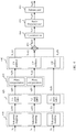
- FIG. 4 is an example diagram according to an embodiment of this application.
- f i indicates a subcarrier spacing of a i (k).
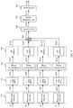
- FIG. 5 is an example diagram according to another embodiment of this application.
- h i (k) a i e j 2 ⁇ k ⁇ ⁇ f i t
- fi indicates a subcarrier spacing of ai(k).
- FIG. 7 is an example diagram according to still another embodiment of this application.
- a transmit end may not perform phase compensation on a synchronization signal, but perform phase compensation on only data.
- the transmit end may notify a terminal of a difference between a center frequency of the synchronization signal and a center frequency of a current carrier or a difference between a center frequency of the synchronization signal and a center frequency of a data channel in a current carrier, and a receive end performs phase compensation based on the difference, so that the receive end can correctly adjust the data.
- a transmit end may perform phase compensation on both a synchronization signal and data. In this case, a receive end can correctly demodulate the data without performing phase compensation.
- a transmit end may perform phase compensation on a synchronization signal, but perform no phase compensation on data.
- a receive end may notify the receive end of a difference between a center frequency of the data and a center frequency of a current carrier, or a difference between a center frequency of the data and a center frequency of a data channel in a current carrier, and the receive end performs phase compensation on the data based on the difference, so that the receive end can correctly adjust the data.
- FIG. 8 is a schematic block diagram of a transmission apparatus 800 according to an embodiment of this application. As shown in FIG. 8 , the transmission apparatus 800 includes a processing module 810 and a communications module 820.
- the processing module 810 is configured to perform a phase compensation operation of a corresponding frequency value on each of m first signals in k signals, to obtain m second signals.
- Each of the m first signals is located at a non-center frequency of a current carrier, each first signal is a synchronization signal or data, m and k each are a positive integer, and m ⁇ k.
- the communications module 820 is configured to perform sending processing on the m second signals.
- the processing module 810 is configured to: perform inverse discrete Fourier transform on each of m first signals in k signals, to obtain m second signals, and perform a phase compensation operation of a corresponding frequency value on each of the m second signals, to obtain m third signals.
- Each of the m first signals is located at a non-center frequency of a current carrier, each first signal is a synchronization signal or data, m and k each are a positive integer, and m ⁇ k.
- the communications module 820 performs sending processing on the m third signals.
- modules in the transmission apparatus 800 are separately configured to perform actions or processing processes performed by the transmit end (for example, the network device) in the foregoing methods, and therefore, can also implement the beneficial effects in the foregoing method embodiments.
- the transmit end for example, the network device
- the modules in the transmission apparatus 800 are separately configured to perform actions or processing processes performed by the transmit end (for example, the network device) in the foregoing methods, and therefore, can also implement the beneficial effects in the foregoing method embodiments.
- the transmit end for example, the network device
- modules in the transmission apparatus 900 are separately configured to perform actions or processing processes performed by the receive end (for example, the terminal device) in the foregoing methods, and therefore, can also implement the beneficial effects in the foregoing method embodiments.
- the receive end for example, the terminal device
- the beneficial effects in the foregoing method embodiments are omitted.
- FIG. 10 is a schematic structural diagram of a transmission apparatus 1000 according to an embodiment of this application.
- the terminal device 1000 includes a transceiver 1010, a processor 1020, and a memory 1030.
- the transceiver 1010, the processor 1020, and the memory 1030 communicate with each other through an internal connection path, to transmit a control signal and/or a data signal.
- the transceiver 1010 is configured to perform sending processing on the m second signals.
- the processor 1020 is configured to: perform inverse discrete Fourier transform on each of m first signals in k signals, to obtain m second signals, and perform a phase compensation operation of a corresponding frequency value on each of the m second signals, to obtain m third signals.
- Each of the m first signals is located at a non-center frequency of a current carrier, each first signal is a synchronization signal or data, m and k each are a positive integer, and m ⁇ k.
- the transceiver 1010 performs sending processing on the m third signals.
- FIG. 11 is a schematic structural diagram of a transmission apparatus 1100 according to an embodiment of this application.
- the terminal device 1100 includes a transceiver 1110, a processor 1120, and a memory 1130.
- the transceiver 1110, the processor 1120, and the memory 1130 communicate with each other through an internal connection path, to transmit a control signal and/or a data signal.
- the processor 1120 is configured to obtain a synchronization signal and a physical broadcast channel.
- the physical broadcast channel includes first indication information, and the first indication information indicates a first difference between a center frequency of the synchronization signal and a center frequency of first data.
- the transceiver 1110 is configured to receive the first data.
- the processor 1120 is further configured to demodulate the first data based on the first difference.
- the processor 1120 when the processor 1120 invokes the computer program from the memory and runs the computer program, the processor 1020 may be configured to: perform a data processing function and/or a signal processing function of the receive end in the foregoing methods, and control the transceiver 1110 to complete a corresponding information receiving and sending function of the receive end.
- the embodiments of this application may be applied to a processor, or implemented by a processor.
- the processor may be an integrated circuit chip and has a signal processing capability.
- steps in the foregoing method embodiments can be implemented by using a hardware integrated logic circuit in the processor, or by using instructions in a form of software.
- the foregoing processor may be a central processing unit (central processing unit, CPU), or the processor may be another general-purpose processor, a digital signal processor (digital signal processor, DSP), an application-specific integrated circuit (application specific integrated circuit, ASIC), a field programmable gate array (field programmable gate array, FPGA) or another programmable logic device, a discrete gate or transistor logic device, or a discrete hardware component.
- the processor may implement or perform the methods, steps, and logical block diagrams that are disclosed in the embodiments of this application.
- the general-purpose processor may be a microprocessor, or the processor may be any conventional processor or the like. Steps of the methods disclosed with reference to the embodiments of this application may be directly performed and accomplished by using a hardware decoding processor, or may be performed and accomplished by using a combination of hardware and a software unit in the decoding processor.
- the software unit may be located in a mature storage medium in the art, such as a random access memory, a flash memory, a read-only memory, a programmable read-only memory, an electrically erasable programmable memory, or a register.
- the storage medium is located in a memory, and the processor reads information in the memory and completes the steps in the foregoing methods in combination with hardware of the processor.
- the receive end chip implements a function of the processing module 910 or the processor 1120.
- the receive end chip receives the foregoing synchronization data and data from another module (for example, a radio frequency module or an antenna) of a receive end.
- the synchronization data and the data are sent to the receive end by using the another module of the receive end.
- the receive end chip may further receive information from another module (for example, a radio frequency module or an antenna) of the receive end, and the information is sent by a transmit end to the receive end.
- the memory in the embodiments of this application may be a volatile memory or a nonvolatile memory, or may include a volatile memory and a nonvolatile memory.
- the nonvolatile memory may be a read-only memory (read-only memory, ROM), a programmable read-only memory (programmable ROM, PROM), an erasable programmable read-only memory (erasable PROM, EPROM), an electrically erasable programmable read-only memory (electrically EPROM, EEPROM), or a flash memory.
- the volatile memory may be a random access memory (random access memory, RAM), and is used as an external cache.
- RAMs may be used, for example, a static random access memory (static RAM, SRAM), a dynamic random access memory (dynamic RAM, DRAM), a synchronous dynamic random access memory (synchronous DRAM, SDRAM), a double data rate synchronous dynamic random access memory (double data rate SDRAM, DDR SDRAM), an enhanced synchronous dynamic random access memory (enhanced SDRAM, ESDRAM), a synchlink dynamic random access memory (synchlink DRAM, SLDRAM), and a direct rambus random access memory (direct rambus RAM, DRRAM).
- static random access memory static random access memory
- DRAM dynamic random access memory
- DRAM dynamic random access memory
- SDRAM synchronous dynamic random access memory
- double data rate SDRAM double data rate SDRAM
- DDR SDRAM double data rate SDRAM
- ESDRAM enhanced synchronous dynamic random access memory
- synchlink dynamic random access memory synchlink dynamic random access memory
- direct rambus RAM direct rambus RAM
- the disclosed apparatus and method may be implemented in other manners.
- the described apparatus embodiments are merely examples.
- division into the units is merely logical function division.
- a plurality of units or components may be combined or integrated into another system, or some features may be ignored or not performed.
- the displayed or discussed mutual couplings or direct couplings or communication connections may be implemented by using some interfaces.
- the indirect couplings or communication connections between the apparatuses or units may be implemented in electronic, mechanical, or other forms.
- function units in the embodiments of this application may be integrated into one processing unit, or each of the units may exist alone physically, or two or more units are integrated into one unit.
- the functions When the functions are implemented in the form of a software function unit and sold or used as an independent product, the functions may be stored in a computer-readable storage medium. Based on such an understanding, the technical solutions of this application essentially, or the part contributing to the prior art, or some of the technical solutions may be implemented in a form of a software product.
- the computer software product is stored in a storage medium, and includes several instructions for instructing a computer device (which may be a personal computer, a server, a network device, or the like) to perform all or some of the steps of the methods described in the embodiments of this application.
Landscapes
- Engineering & Computer Science (AREA)
- Signal Processing (AREA)
- Computer Networks & Wireless Communication (AREA)
- Physics & Mathematics (AREA)
- Discrete Mathematics (AREA)
- General Physics & Mathematics (AREA)
- Mathematical Physics (AREA)
- Mobile Radio Communication Systems (AREA)
Applications Claiming Priority (2)
| Application Number | Priority Date | Filing Date | Title |
|---|---|---|---|
| CN201710854113.1A CN109510791B (zh) | 2017-09-15 | 2017-09-15 | 传输方法和传输装置 |
| PCT/CN2018/105400 WO2019052494A1 (fr) | 2017-09-15 | 2018-09-13 | Procédé de transmission et appareil de transmission |
Publications (2)
| Publication Number | Publication Date |
|---|---|
| EP3678341A1 true EP3678341A1 (fr) | 2020-07-08 |
| EP3678341A4 EP3678341A4 (fr) | 2020-10-14 |
Family
ID=65722438
Family Applications (1)
| Application Number | Title | Priority Date | Filing Date |
|---|---|---|---|
| EP18856689.7A Withdrawn EP3678341A4 (fr) | 2017-09-15 | 2018-09-13 | Procédé de transmission et appareil de transmission |
Country Status (4)
| Country | Link |
|---|---|
| US (1) | US11146374B2 (fr) |
| EP (1) | EP3678341A4 (fr) |
| CN (1) | CN109510791B (fr) |
| WO (1) | WO2019052494A1 (fr) |
Families Citing this family (6)
| Publication number | Priority date | Publication date | Assignee | Title |
|---|---|---|---|---|
| CN109510791B (zh) * | 2017-09-15 | 2024-10-11 | 华为技术有限公司 | 传输方法和传输装置 |
| US11109382B2 (en) | 2019-07-22 | 2021-08-31 | Dish Wireless L.L.C. | Multiple concurrent bandwidth parts for a base station of a cellular network |
| US10932269B2 (en) | 2019-07-22 | 2021-02-23 | Dish Wireless L.L.C. | Bandwidth adjustment of multiple concurrent bandwidth parts for a base station of a cellular network |
| CN112702745A (zh) * | 2019-10-22 | 2021-04-23 | 中兴通讯股份有限公司 | 产生共享载波的方法和装置、处理共享载波的方法和装置 |
| US11956111B2 (en) * | 2020-02-14 | 2024-04-09 | Huawei Technologies Co., Ltd. | Multi-rate crest factor reduction |
| US11316656B1 (en) * | 2020-07-08 | 2022-04-26 | The Johns Hopkins University | Time transfer modem |
Family Cites Families (63)
| Publication number | Priority date | Publication date | Assignee | Title |
|---|---|---|---|---|
| JP3437445B2 (ja) * | 1998-05-22 | 2003-08-18 | 松下電器産業株式会社 | 線形信号予測を用いた受信装置及び方法 |
| US7206350B2 (en) * | 2001-06-11 | 2007-04-17 | Unique Broadband Systems, Inc. | OFDM multiple sub-channel communication system |
| US7020226B1 (en) * | 2002-04-04 | 2006-03-28 | Nortel Networks Limited | I/Q distortion compensation for the reception of OFDM signals |
| JP4703135B2 (ja) * | 2004-05-25 | 2011-06-15 | 株式会社エヌ・ティ・ティ・ドコモ | 送信機および送信制御方法 |
| KR101137329B1 (ko) * | 2005-06-15 | 2012-04-19 | 엘지전자 주식회사 | 다중 반송파 시스템에서의 부반송파 할당 방법 및 그 장치 |
| WO2007066973A2 (fr) * | 2005-12-06 | 2007-06-14 | Lg Electronics Inc. | Dispositif et procede de transmission de donnees au moyen d'une pluralite de porteuses |
| KR100795559B1 (ko) * | 2005-12-09 | 2008-01-21 | 한국전자통신연구원 | 직교 주파수 분할 다중화 방식의 무선 시스템에서 고주파왜곡 현상의 보상 장치 및 방법 |
| US7675983B2 (en) * | 2006-04-14 | 2010-03-09 | Freescale Semiconductor, Inc. | Mitigation of DC distortion in OFDM receivers |
| CN101461203B (zh) * | 2006-06-14 | 2013-03-27 | 艾格瑞系统有限公司 | 调制数据符号集的方法和设备及相应的解调方法和设备 |
| EP1876730A1 (fr) * | 2006-07-05 | 2008-01-09 | Koninklijke Philips Electronics N.V. | Système de communication avec bande passante asymmétrique |
| WO2008026891A1 (fr) * | 2006-08-30 | 2008-03-06 | Posdata Co., Ltd. | Appareil et procédé permettant d'estimer et de compenser le décalage temporel et/ou le décalage de fréquence porteuse dans un mrof/amrof basé sur un système entrée multiple sortie multiple |
| KR100830614B1 (ko) * | 2006-10-10 | 2008-05-22 | 한국전자통신연구원 | 다중 안테나 송신 시스템 및 이를 이용한 신호 전송 방법 |
| US8761303B2 (en) * | 2008-11-13 | 2014-06-24 | Qualcomm Incorporated | Unequal multipath protection of different frames within a superframe using different cyclic prefix lengths |
| WO2010082805A2 (fr) * | 2009-01-19 | 2010-07-22 | 엘지전자 주식회사 | Procédé de configuration d'une onde porteuse dans un système d'agrégation de fréquence et appareil correspondant |
| KR101496896B1 (ko) * | 2009-02-16 | 2015-02-27 | 삼성전자주식회사 | 대역 확장성을 지원하는 셀룰러 무선통신시스템에서 보호대역이 구성된 하향링크 신호의 송수신 방법 및 장치 |
| US8559950B2 (en) * | 2010-02-01 | 2013-10-15 | Intel Mobile Communications GmbH | Radio base stations, radio communication devices, methods for controlling a radio base station, and methods for controlling a radio communication device |
| KR101253197B1 (ko) * | 2010-03-26 | 2013-04-10 | 엘지전자 주식회사 | 참조신호 수신 방법 및 사용자기기, 참조신호 전송 방법 및 기지국 |
| EP2385663B1 (fr) * | 2010-05-07 | 2016-01-06 | Telefonaktiebolaget L M Ericsson (publ) | Compensation de décalage de fréquence pour systèmes de communication multiporteur |
| US9445432B2 (en) * | 2010-06-25 | 2016-09-13 | Microsoft Technology Licensing, Llc | Fine-grained channel access in wireless networks |
| KR20130018079A (ko) * | 2011-08-10 | 2013-02-20 | 삼성전자주식회사 | 무선 통신 시스템에서 빔 고정 장치 및 방법 |
| FR2985134A1 (fr) * | 2011-12-23 | 2013-06-28 | France Telecom | Procede d'emission d'au moins un signal multi-porteuse forme de symboles ofdm-oqam |
| US9473332B2 (en) * | 2012-04-27 | 2016-10-18 | The Royal Institution For The Advancement Of Learning / Mcgill University | Methods and devices for communications systems using multiplied rate transmission |
| WO2015064868A1 (fr) * | 2013-11-04 | 2015-05-07 | Lg Electronics Inc. | Pré-compensation de l'erreur de déplacement de phase |
| US9825687B2 (en) * | 2013-11-08 | 2017-11-21 | Lg Electronics Inc. | Pre-compensation of the phase shifting error |
| KR102143466B1 (ko) * | 2014-01-03 | 2020-08-12 | 삼성전자주식회사 | 송신 장치, 수신 장치 및 그 제어 방법 |
| NO2705215T3 (fr) * | 2014-01-31 | 2018-02-17 | ||
| KR20170051437A (ko) * | 2014-08-07 | 2017-05-11 | 코히어런트 로직스, 인코포레이티드 | 멀티-파티션 라디오 프레임 |
| CA3016736C (fr) * | 2014-08-07 | 2019-12-17 | ONE Media, LLC | Configuration dynamique d'une trame flexible de donnees de transport/phy a multiplexage par repartition orthogonale de la frequence |
| KR101926004B1 (ko) * | 2014-11-07 | 2018-12-06 | 후아웨이 테크놀러지 컴퍼니 리미티드 | 직류 컴포넌트 부반송파 구성 방법 및 장치 |
| EP3276860B1 (fr) * | 2015-03-26 | 2019-09-04 | NTT DoCoMo, Inc. | Procédé de commande de radiocommunication et système de radiocommunication |
| US10069666B2 (en) * | 2015-07-20 | 2018-09-04 | Telefonaktiebolaget Lm Ericsson (Publ) | Transceiver architecture that maintains legacy timing by inserting and removing cyclic prefix at legacy sampling rate |
| US10117199B2 (en) * | 2015-09-24 | 2018-10-30 | Lg Electronics Inc. | Method of transmitting channel state information and apparatus therefor |
| CN108476078B (zh) * | 2016-01-15 | 2020-10-27 | 苹果公司 | 用于信道栅格频率偏移的通信的演进节点B(eNB)、用户设备(UE)和方法 |
| CN107370704A (zh) * | 2016-05-13 | 2017-11-21 | 财团法人工业技术研究院 | 无线通信设备及无线信号产生方法 |
| WO2018048187A1 (fr) * | 2016-09-06 | 2018-03-15 | Lg Electronics Inc. | Procédé et appareil de configuration de structure de bloc de ressources pour nr dans un système de communication sans fil |
| CN106453187B (zh) * | 2016-09-26 | 2019-06-11 | 珠海全志科技股份有限公司 | 一种ofdm系统同步跟踪方法和装置 |
| CN107872868B (zh) * | 2016-09-26 | 2020-04-03 | 华为技术有限公司 | 信号处理的方法、设备和系统 |
| US10673672B2 (en) * | 2016-09-30 | 2020-06-02 | Motorola Mobility Llc | Method and apparatus for synchronization signals and random access for flexible radio communication |
| CN110291735B (zh) * | 2016-12-05 | 2022-03-18 | 瑞典爱立信有限公司 | 控制节点、测量节点及用于其的方法 |
| EP3596984B1 (fr) * | 2017-04-17 | 2022-07-20 | Samsung Electronics Co., Ltd. | Procédé et dispositif de régulation de puissance de liaison montante |
| CN110771238B (zh) * | 2017-06-16 | 2024-05-14 | 瑞典爱立信有限公司 | 为用户设备配置用于传送调度请求的重叠的pucch资源的系统和方法 |
| CN111052655B (zh) * | 2017-08-10 | 2025-04-25 | 华为技术有限公司 | 发送设备、接收设备及其方法 |
| CN109391578B (zh) * | 2017-08-11 | 2022-07-22 | 华为技术有限公司 | 信号发送方法、信号接收方法、终端设备及网络设备 |
| CN109510791B (zh) * | 2017-09-15 | 2024-10-11 | 华为技术有限公司 | 传输方法和传输装置 |
| WO2019062867A1 (fr) * | 2017-09-28 | 2019-04-04 | Telefonaktiebolaget Lm Ericsson (Publ) | Commutation de parties de bande passante dans un réseau de communication sans fil |
| KR102445754B1 (ko) * | 2017-10-10 | 2022-09-22 | 텔레호낙티에볼라게트 엘엠 에릭슨(피유비엘) | 물리적 업링크 제어 채널 폴백 모드 |
| US10536308B2 (en) * | 2017-10-16 | 2020-01-14 | Analog Devices Global Unlimited Company | Automatic gain control (AGC) assisted carrier offset correction |
| WO2019081627A1 (fr) * | 2017-10-27 | 2019-05-02 | Telefonaktiebolaget Lm Ericsson (Publ) | Dm-rs de signaux pi/2-bpsk |
| US10652854B2 (en) * | 2017-10-30 | 2020-05-12 | Qualcomm Incorporated | Paging super frame window for narrowband communications using the unlicensed spectrum |
| US20200389883A1 (en) * | 2017-11-16 | 2020-12-10 | Telefonaktiebolaget Lm Ericsson (Publ) | Configuring spatial qcl reference in a tci state |
| EP3711240A1 (fr) * | 2017-11-17 | 2020-09-23 | Telefonaktiebolaget LM Ericsson (publ) | Amélioration du décodage à l'aide d'informations de perforation connues |
| WO2019101371A1 (fr) * | 2017-11-24 | 2019-05-31 | Huawei Technologies Co., Ltd. | Dispositif de traitement pour un nœud d'accès au réseau permettant de générer des symboles de modulation à compensation de phase |
| US10707915B2 (en) * | 2017-12-04 | 2020-07-07 | Qualcomm Incorporated | Narrowband frequency hopping mechanisms to overcome bandwidth restrictions in the unlicensed frequency spectrum |
| US10784999B2 (en) * | 2017-12-08 | 2020-09-22 | Qualcomm Incorporated | Narrowband physical broadcast channel design on multiple anchor channels |
| US11457472B2 (en) * | 2017-12-18 | 2022-09-27 | Samsung Electronics Co., Ltd. | Method and apparatus for initial access block on stand-alone NR unlicensed spectrum |
| KR102052381B1 (ko) * | 2018-01-24 | 2020-01-07 | 엘지전자 주식회사 | Ofdm 신호 전송 방법 및 전송장치와, ofdm 신호 수신방법 및 수신장치 |
| US10862581B2 (en) * | 2018-01-30 | 2020-12-08 | Qualcomm Incorporated | Dynamic time division duplex (TDD) frame structure for hopping superframes |
| BR112020017498A2 (pt) * | 2018-02-28 | 2020-12-22 | Telefonaktiebolaget Lm Ericsson (Publ) | Métodos realizados por um equipamento de usuário e por um nó de rede, equipamento de usuário, e, nó de rede |
| US10469184B1 (en) * | 2018-04-17 | 2019-11-05 | Analog Devices, Inc. | Radio frequency ranging using phase difference |
| CN113169845A (zh) * | 2018-09-28 | 2021-07-23 | 瑞典爱立信有限公司 | 用于支持配置的准予传输和重传的方法 |
| WO2020167019A1 (fr) * | 2019-02-14 | 2020-08-20 | Samsung Electronics Co., Ltd. | Procédé, dispositif terminal, station de base, support lisible par ordinateur pour mesurer une interférence de liaison croisée, et procédés et appareils pour attribution, détermination, et transmission de données, de préambule d'accès aléatoire |
| CN110477951B (zh) * | 2019-08-30 | 2020-08-25 | 浙江大学 | 基于宽频带声学超材料的超快复合平面波成像方法 |
| ES3004959T3 (en) * | 2019-11-08 | 2025-03-13 | Ericsson Telefon Ab L M | Determining phase tracking reference signals in multiple transmission points |
-
2017
- 2017-09-15 CN CN201710854113.1A patent/CN109510791B/zh active Active
-
2018
- 2018-09-13 WO PCT/CN2018/105400 patent/WO2019052494A1/fr not_active Ceased
- 2018-09-13 EP EP18856689.7A patent/EP3678341A4/fr not_active Withdrawn
-
2020
- 2020-03-13 US US16/818,885 patent/US11146374B2/en active Active
Also Published As
| Publication number | Publication date |
|---|---|
| CN109510791A (zh) | 2019-03-22 |
| CN109510791B (zh) | 2024-10-11 |
| US11146374B2 (en) | 2021-10-12 |
| EP3678341A4 (fr) | 2020-10-14 |
| WO2019052494A1 (fr) | 2019-03-21 |
| US20200213060A1 (en) | 2020-07-02 |
Similar Documents
| Publication | Publication Date | Title |
|---|---|---|
| US11665656B2 (en) | Information transmission method and information transmission apparatus | |
| US11146374B2 (en) | Transmission method and transmission apparatus | |
| US11582806B2 (en) | Communication method and apparatus | |
| CN119402153A (zh) | 确定参考信号序列的方法、装置、计算机程序产品及计算机可读存储介质 | |
| US11632207B2 (en) | Method and apparatus for transmitting uplink signal | |
| US10938526B2 (en) | Signal sending method, signal receiving method, terminal device, and network device | |
| US11558865B2 (en) | Resource indication method, base station and terminal | |
| US12132570B2 (en) | Sequence-based signal transmission method and communication apparatus | |
| AU2017442042A1 (en) | Wireless communication method and apparatus | |
| EP3576363B1 (fr) | Procédé de transmission d'informations de porteuse, station de base et terminal | |
| EP4040711B1 (fr) | Procédé de communication sans fil, dispositif de réseau et dispositif terminal | |
| US20210160874A1 (en) | Signal transmission method and device | |
| EP3661144B1 (fr) | Procédé d'envoi de signal, procédé de réception de signal, dispositif terminal et dispositif de réseau | |
| US10405288B2 (en) | Supporting various bandwidth |
Legal Events
| Date | Code | Title | Description |
|---|---|---|---|
| STAA | Information on the status of an ep patent application or granted ep patent |
Free format text: STATUS: THE INTERNATIONAL PUBLICATION HAS BEEN MADE |
|
| PUAI | Public reference made under article 153(3) epc to a published international application that has entered the european phase |
Free format text: ORIGINAL CODE: 0009012 |
|
| STAA | Information on the status of an ep patent application or granted ep patent |
Free format text: STATUS: REQUEST FOR EXAMINATION WAS MADE |
|
| 17P | Request for examination filed |
Effective date: 20200330 |
|
| AK | Designated contracting states |
Kind code of ref document: A1 Designated state(s): AL AT BE BG CH CY CZ DE DK EE ES FI FR GB GR HR HU IE IS IT LI LT LU LV MC MK MT NL NO PL PT RO RS SE SI SK SM TR |
|
| AX | Request for extension of the european patent |
Extension state: BA ME |
|
| A4 | Supplementary search report drawn up and despatched |
Effective date: 20200910 |
|
| RIC1 | Information provided on ipc code assigned before grant |
Ipc: H04L 27/26 20060101ALI20200904BHEP Ipc: H04L 27/00 20060101AFI20200904BHEP |
|
| DAV | Request for validation of the european patent (deleted) | ||
| DAX | Request for extension of the european patent (deleted) | ||
| STAA | Information on the status of an ep patent application or granted ep patent |
Free format text: STATUS: THE APPLICATION HAS BEEN WITHDRAWN |
|
| 18W | Application withdrawn |
Effective date: 20210910 |