EP3678391A1 - Dispositif de terminal de communication sans fil, dispositif de station de base de communication sans fil et procédé de réglage de région ressource - Google Patents
Dispositif de terminal de communication sans fil, dispositif de station de base de communication sans fil et procédé de réglage de région ressource Download PDFInfo
- Publication number
- EP3678391A1 EP3678391A1 EP20160174.7A EP20160174A EP3678391A1 EP 3678391 A1 EP3678391 A1 EP 3678391A1 EP 20160174 A EP20160174 A EP 20160174A EP 3678391 A1 EP3678391 A1 EP 3678391A1
- Authority
- EP
- European Patent Office
- Prior art keywords
- component band
- downlink
- terminal
- downlink component
- band
- Prior art date
- Legal status (The legal status is an assumption and is not a legal conclusion. Google has not performed a legal analysis and makes no representation as to the accuracy of the status listed.)
- Granted
Links
Images


Classifications
-
- H—ELECTRICITY
- H04—ELECTRIC COMMUNICATION TECHNIQUE
- H04L—TRANSMISSION OF DIGITAL INFORMATION, e.g. TELEGRAPHIC COMMUNICATION
- H04L5/00—Arrangements affording multiple use of the transmission path
- H04L5/003—Arrangements for allocating sub-channels of the transmission path
- H04L5/0053—Allocation of signalling, i.e. of overhead other than pilot signals
- H04L5/0055—Physical resource allocation for ACK/NACK
-
- H—ELECTRICITY
- H04—ELECTRIC COMMUNICATION TECHNIQUE
- H04L—TRANSMISSION OF DIGITAL INFORMATION, e.g. TELEGRAPHIC COMMUNICATION
- H04L5/00—Arrangements affording multiple use of the transmission path
- H04L5/0001—Arrangements for dividing the transmission path
- H04L5/0003—Two-dimensional division
- H04L5/0005—Time-frequency
- H04L5/0007—Time-frequency the frequencies being orthogonal, e.g. OFDM(A) or DMT
- H04L5/001—Time-frequency the frequencies being orthogonal, e.g. OFDM(A) or DMT the frequencies being arranged in component carriers
-
- H—ELECTRICITY
- H04—ELECTRIC COMMUNICATION TECHNIQUE
- H04W—WIRELESS COMMUNICATION NETWORKS
- H04W72/00—Local resource management
- H04W72/50—Allocation or scheduling criteria for wireless resources
- H04W72/54—Allocation or scheduling criteria for wireless resources based on quality criteria
- H04W72/542—Allocation or scheduling criteria for wireless resources based on quality criteria using measured or perceived quality
-
- H—ELECTRICITY
- H04—ELECTRIC COMMUNICATION TECHNIQUE
- H04L—TRANSMISSION OF DIGITAL INFORMATION, e.g. TELEGRAPHIC COMMUNICATION
- H04L27/00—Modulated-carrier systems
- H04L27/26—Systems using multi-frequency codes
- H04L27/2601—Multicarrier modulation systems
- H04L27/2626—Arrangements specific to the transmitter only
- H04L27/2627—Modulators
- H04L27/2634—Inverse fast Fourier transform [IFFT] or inverse discrete Fourier transform [IDFT] modulators in combination with other circuits for modulation
-
- H—ELECTRICITY
- H04—ELECTRIC COMMUNICATION TECHNIQUE
- H04L—TRANSMISSION OF DIGITAL INFORMATION, e.g. TELEGRAPHIC COMMUNICATION
- H04L27/00—Modulated-carrier systems
- H04L27/26—Systems using multi-frequency codes
- H04L27/2601—Multicarrier modulation systems
- H04L27/2647—Arrangements specific to the receiver only
- H04L27/2649—Demodulators
- H04L27/26524—Fast Fourier transform [FFT] or discrete Fourier transform [DFT] demodulators in combination with other circuits for demodulation
-
- H—ELECTRICITY
- H04—ELECTRIC COMMUNICATION TECHNIQUE
- H04W—WIRELESS COMMUNICATION NETWORKS
- H04W4/00—Services specially adapted for wireless communication networks; Facilities therefor
- H04W4/06—Selective distribution of broadcast services, e.g. multimedia broadcast multicast service [MBMS]; Services to user groups; One-way selective calling services
-
- H—ELECTRICITY
- H04—ELECTRIC COMMUNICATION TECHNIQUE
- H04W—WIRELESS COMMUNICATION NETWORKS
- H04W72/00—Local resource management
- H04W72/04—Wireless resource allocation
- H04W72/044—Wireless resource allocation based on the type of the allocated resource
- H04W72/0453—Resources in frequency domain, e.g. a carrier in FDMA
-
- H—ELECTRICITY
- H04—ELECTRIC COMMUNICATION TECHNIQUE
- H04L—TRANSMISSION OF DIGITAL INFORMATION, e.g. TELEGRAPHIC COMMUNICATION
- H04L5/00—Arrangements affording multiple use of the transmission path
- H04L5/0001—Arrangements for dividing the transmission path
- H04L5/0014—Three-dimensional division
- H04L5/0016—Time-frequency-code
-
- H—ELECTRICITY
- H04—ELECTRIC COMMUNICATION TECHNIQUE
- H04W—WIRELESS COMMUNICATION NETWORKS
- H04W72/00—Local resource management
- H04W72/20—Control channels or signalling for resource management
- H04W72/21—Control channels or signalling for resource management in the uplink direction of a wireless link, i.e. towards the network
Definitions
- a terminal is a radio communication terminal apparatus that performs communication using a plurality of downlink component bands, and adopts a configuration including a receiving section that obtains CFI information indicating the number of symbols used for a control channel to which resource allocation information of downlink data directed to the radio communication terminal apparatus is allocated for each of the plurality of downlink component bands, a setting section that sets, in the uplink component band set in the terminal apparatus, a resource area to which a response signal corresponding to the downlink data for each of the plurality of downlink component bands based on the CFI information for each of the plurality of downlink component bands and a mapping section that maps the response signal to the resource area corresponding to the downlink component band used to allocate the downlink data.
- a resource area setting method is a method for a radio communication terminal apparatus that performs communication using a plurality of downlink component bands, obtaining CFI information indicating the number of symbols used for a control channel to which resource allocation information of downlink data directed to the radio communication terminal apparatus is allocated for each of the plurality of downlink component bands and setting, in an uplink component band set in the radio communication terminal apparatus, a resource area to which a response signal corresponding to the downlink data is allocated for each of the plurality of downlink component bands based on the CFI information for each of the plurality of downlink component bands.
- the present invention even when a plurality of ACK/NACK signals corresponding to downlink data transmitted in each of a plurality of downlink component bands are transmitted from one uplink component band, it is possible to reduce the PUCCH areas (number of ACK/NACK resources) in an uplink component band without increasing signaling.
- a base station allocates downlink data using PDCCHs arranged in two downlink component bands and transmits the downlink data to a terminal. Furthermore, the terminal feeds back an ACK/NACK signal corresponding to the downlink data transmitted using the two downlink component bands to the base station using a PUCCH arranged in one uplink component band.
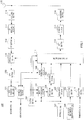
- FIG.1 is a block diagram illustrating a configuration of base station 100 according to the present embodiment.
- setting section 101 sets (configures) one or a plurality of component bands to use for an uplink and a downlink per terminal according to a required transmission rate and amount of data transmission or the like. For example, setting section 101 sets an uplink component band and a downlink component band to use for data transmission and an uplink component band to use for PUCCH transmission. Setting section 101 then outputs setting information including the component band set in each terminal to control section 102, PDCCH generation section 103 and modulation section 107.
- Control section 102 generates uplink resource allocation information indicating uplink resources (e.g. PUSCH) to which uplink data of a terminal is allocated and downlink resource allocation information indicating downlink resources (e.g. PDSCH (Physical Downlink Shared Channel)) to which downlink data directed to the terminal is allocated. Control section 102 then outputs the uplink resource allocation information to PDCCH generation section 103 and extraction section 119 and outputs the downlink resource allocation information to PDCCH generation section 103 and multiplexing section 111. Here, control section 102 allocates uplink resource allocation information and downlink resource allocation information to PDCCHs arranged in downlink component bands set in each terminal based on the setting information inputted from setting section 101.
- uplink resource allocation information indicating uplink resources (e.g. PUSCH) to which uplink data of a terminal is allocated
- downlink resource allocation information indicating downlink resources e.g. PDSCH (Physical Downlink Shared Channel)
- Control section 102 then outputs the uplink resource allocation information
- control section 102 allocates the downlink resource allocation information to PDCCHs arranged in the downlink component bands to be subjected to resource allocation indicated in the downlink resource allocation information. Furthermore, control section 102 allocates uplink resource allocation information to PDCCHs arranged in downlink component bands associated with the uplink component bands to be subjected to resource allocation indicated in the uplink allocation information.
- a PDCCH is made up of one or a plurality of CCEs. Furthermore, the number of CCEs used by base station 100 is set based on propagation path quality (CQI: Channel Quality Indicator) of the allocation target terminal are and a control information size so that the terminal can receive control information at a necessary and sufficient error rate.
- CQI Channel Quality Indicator
- control section 102 determines, for each component band, the number of OFDM symbols to use for transmission of PDCCHs based on the number of CCEs to use for PDCCHs to which control information (e.g. allocation information) is allocated in each downlink component and generates CFI information indicating the determined number of OFDM symbols. That is, control section 102 generates, for each of the plurality of downlink component bands, CFI information indicating the number of OFDM symbols to use for a PDCCH to which resource allocation information (uplink resource allocation information or downlink resource allocation information) of downlink data directed to the terminal is allocated for the terminal that communicates using a plurality of downlink component bands. Control section 102 then outputs CFI information per downlink component band to PCFICH generation section 106, multiplexing section 111 and ACK/NACK receiving section 122.
- control information e.g. allocation information
- PDCCH generation section 103 generates a PDCCH signal including the uplink resource allocation information and downlink resource allocation information inputted from control section 102. Furthermore, PDCCH generation section 103 adds a CRC bit to the PDCCH signal to which the uplink resource allocation information and downlink resource allocation information have been allocated and further masks (or scrambles) the CRC bit with the terminal ID. PDCCH generation section 103 then outputs the masked PDCCH signal to modulation section 104.
- Modulation section 104 modulates the PDCCH signal inputted from PDCCH generation section 103 after channel coding and outputs the modulated PDCCH signal to allocation section 105.
- Allocation section 105 allocates the PDCCH signal of each terminal inputted from modulation section 104 to a CCE in a search space per terminal in a downlink component band in each component band. For example, allocation section 105 calculates a search space of each of the plurality of downlink component bands set in each terminal from the terminal ID of each terminal, CCE number calculated using a hash function for performing randomization and the number of CCEs (L) making up the search space. That is, allocation section 105 sets the CCE number calculated using the terminal ID of a certain terminal and a hash function at the starting position (CCE number) of the search space of the terminal and sets consecutive CCEs corresponding to the number of CCEs L from the starting position as the search space of the terminal.
- CCE number the starting position
- allocation section 105 sets the same search space (search space made up of CCEs of the same CCE number) between a plurality of downlink component bands set per terminal. Allocation section 105 then outputs the PDCCH signal allocated to the CCE to multiplexing section 111. Furthermore, allocation section 105 outputs the CCE number of the CCE to which the PDCCH signal has been allocated to ACK/NACK receiving section 122.
- PCFICH generation section 106 generates a PCFICH signal based on CFI information per downlink component band inputted from control section 102. For example, PCFICH generation section 106 generates information of 32 bits by coding CFI information (CFI bits) of 2 bits of each downlink component band, QPSK-modulates the generated information of 32 bits and thereby generates a PCFICH signal. PCFICH generation section 106 then outputs the generated PCFICH signal to multiplexing section 111.
- CFI information CFI bits
- Broadcast information generation section 108 sets operation parameters (system information (SIB: System Information Block)) of the cell of the base station and generates broadcast information including the set system information (SIB).
- SIB System Information Block
- base station 100 broadcasts system information of each uplink component band using a downlink component band associated with the uplink component band.
- the system information of the uplink component band include PUCCH area information indicating the starting position (resource number) of the PUCCH area to use for transmission of an ACK/NACK signal.
- Broadcast information generation section 108 then outputs the broadcast information including the system information (SIB) of the cell of the base station including the PUCCH area information or the like to modulation section 109.
- Modulation section 109 modulates the broadcast information inputted from broadcast information generation section 108 and outputs the modulated broadcast information to multiplexing section 111.
- Modulation section 110 modulates inputted transmission data (downlink data) after channel coding and outputs the modulated transmission data signal to multiplexing section 111.
- Multiplexing section 111 multiplexes the PDCCH signal inputted from allocation section 105, PCFICH signal inputted from PCFICH generation section 106, setting information inputted from modulation section 107, broadcast information inputted from modulation section 109 and data signal (that is, PDSCH signal) inputted from modulation section 110.
- multiplexing section 111 determines the number of OFDM symbols in which PDCCHs are arranged for each downlink component band based on the CFI information inputted from control section 102.
- multiplexing section 111 maps the PDCCH signal and data signal (PDSCH signal) to each downlink component band based on the downlink resource allocation information inputted from control section 102.
- Multiplexing section 111 may also map the setting information to a PDSCH.
- Multiplexing section 111 then outputs the multiplexed signal to IFFT (Inverse Fast Fourier Transform) section 112.
- IFFT Inverse Fast Fourier Transform
- IFFT section 112 transforms the multiplexed signal inputted from multiplexing section 111 into a time waveform and CP (Cyclic Prefix) adding section 110 adds a CP to the time waveform and thereby obtains an OFDM signal.
- CP Cyclic Prefix
- RF transmitting section 114 applies radio transmission processing (up-conversion, D/A conversion or the like) to the OFDM signal inputted from CP adding section 113 and transmits the OFDM signal via antenna 115.
- RF receiving section 116 applies radio receiving processing (down-conversion, A/D conversion or the like) to a received radio signal received in a reception band via antenna 115 and outputs the received signal obtained to CP removing section 117.
- radio receiving processing down-conversion, A/D conversion or the like
- CP removing section 114 removes a CP from the received signal and FFT (Fast Fourier Transform) section 115 transforms the received signal after the CP removal into a frequency domain signal.
- FFT Fast Fourier Transform
- Extraction section 119 extracts uplink data of each terminal and PUCCH signal (e.g. ACK/NACK signal) from the frequency domain signal inputted from FFT section 118 based on the uplink resource allocation information (e.g. uplink resource allocation information 4 subframes ahead) inputted from control section 102.
- IDFT Inverse Discrete Fourier transform
- section 120 transforms the signal extracted by extraction section 119 into a time domain signal and outputs the time domain signal to data receiving section 121 and ACK/NACK receiving section 122.
- Data receiving section 121 decodes uplink data out of the time domain signal inputted from IDFT section 120. Data receiving section 121 outputs the decoded uplink data as received data.
- ACK/NACK receiving section 122 extracts an ACK/NACK signal from each terminal corresponding to the downlink data (PDSCH signal) out of the time domain signal inputted from IDFT section 120. To be more specific, ACK/NACK receiving section 122 extracts, in an uplink component band set in each terminal, an ACK/NACK signal from a PUCCH (ACK/NACK resource) associated with a CCE used for the PDCCH signal out of the PUCCH area corresponding to the downlink component band in which the PDCCH signal used to allocate the downlink data is arranged.
- PUCCH ACK/NACK resource
- the PUCCH area is identified from the number of CCEs available in each downlink component band inputted from control section 102 and calculated from the CFI information of each downlink component band, and a downlink component band number.
- base station 100 allocates a PDCCH signal including downlink resource allocation information of downlink data (PDSCH signal) of a plurality of component bands to CCEs of a plurality of downlink component bands for a certain terminal
- ACK/NACK receiving section 122 extracts an ACK/NACK signal from the PUCCH (ACK/NACK resource) associated with the CCE number of the CCE used to allocate the downlink data in the PUCCH areas corresponding to the respective downlink component bands.
- ACK/NACK receiving section 122 identifies a PUCCH area to which an ACK/NACK signal corresponding to downlink data is allocated based on the number of CCEs available for each of a plurality of downlink component bands calculated based on the CFI information for each of the plurality of downlink component bands set in the terminal in the uplink component band set in the terminal. ACK/NACK receiving section 122 then extracts the ACK/NACK signal from the PUCCH area corresponding to the downlink component band used to allocate the downlink data. Thus, ACK/NACK receiving section 122 obtains each ACK/NACK signal corresponding to downlink data of a plurality of component bands. ACK/NACK receiving section 122 then makes an ACK/NACK decision on the extracted ACK/NACK signal.
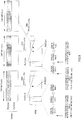
- FIG.2 is a block diagram illustrating a configuration of terminal 200 according to the present embodiment.
- Terminal 200 receives a data signal (downlink data) using a plurality of downlink component bands and transmits an ACK/NACK signal for the data signal to base station 100 using a PUCCH of one uplink component band.
- a data signal downlink data
- ACK/NACK signal for the data signal to base station 100 using a PUCCH of one uplink component band.
- RF receiving section 202 is configured to be able to change a reception band and changes the reception band based on band information inputted from setting information receiving section 207. RF receiving section 202 then applies radio receiving processing (down-conversion, A/D conversion or the like) to the received radio signal (here, OFDM signal) received in the reception band via antenna 201 and outputs the received signal obtained to CP removing section 203.
- radio receiving processing down-conversion, A/D conversion or the like
- CP removing section 203 removes a CP from the received signal and FFT section 204 transforms the received signal after the CP removal into a frequency domain signal.
- the frequency domain signal is outputted to demultiplexing section 205.
- Demultiplexing section 205 demultiplexes the signal inputted from FFT section 204 into broadcast information including system information per cell including PUCCH area information indicating the PUCCH area, a control signal (e.g. RRC signaling) of a higher layer including setting information, a PCFICH signal, a PDCCH signal and a data signal (that is, PDSCH signal).
- Demultiplexing section 205 then outputs the broadcast information to broadcast information receiving section 206, outputs the control signal to setting information receiving section 207, outputs the PCFICH signal to PCFICH receiving section 208, outputs the PDCCH signal to PDCCH receiving section 209 and outputs the PDSCH signal to PDSCH receiving section 210.
- Broadcast information receiving section 206 reads system information (SIB) from the broadcast information inputted from demultiplexing section 205. Furthermore, broadcast information receiving section 206 outputs PUCCH area information included in the system information of the downlink component band associated with the uplink component band to use for PUCCH transmission to mapping section 214.
- the PUCCH area information includes the starting position (resource number) of the PUCCH area of the uplink component band and is broadcast, for example, with SIB2 (system information block type 2).
- Setting information receiving section 207 reads the uplink component band and downlink component band to use for data transmission set in the terminal and information indicating the uplink component band to use for PUCCH transmission from the control signal inputted from demultiplexing section 205. Setting information receiving section 207 then outputs the read information to PDCCH receiving section 209, RF receiving section 202 and RF transmitting section 217 as band information. Furthermore, setting information receiving section 207 reads information indicating the terminal ID set in the terminal from the control signal inputted from demultiplexing section 205 and outputs the read information to PDCCH receiving section 209 as terminal ID information.
- PCFICH receiving section 208 extracts CFI information from the PCFICH signal inputted from demultiplexing section 205. That is, PCFICH receiving section 208 obtains the CFI information indicating the number of OFDM symbols to use for a PDCCH to which resource allocation information of downlink data directed to the terminal is allocated for each of the plurality of downlink component bands set in the terminal. PCFICH receiving section 208 then outputs the extracted CFI information to PDCCH receiving section 209 and mapping section 214.
- PDCCH receiving section 209 blind-decodes the PDCCH signal inputted from demultiplexing section 205 and obtains a PDCCH signal (resource allocation information) directed to the terminal.
- the PDCCH signal is allocated to each CCE (that is, PDCCH) arranged in the downlink component band set in the terminal indicated in the band information inputted from setting information receiving section 207.
- PDCCH receiving section 209 identifies the number of OFDM symbols in which the PDCCH is arranged for each downlink component band based on the CFI information inputted from PCFICH receiving section 208.
- PDCCH receiving section 209 then calculates a search space of the terminal using the terminal ID of the terminal indicated in the terminal ID information inputted from setting information receiving section 207.
- All search spaces (CCE numbers of CCEs constituting the search space) calculated here are the same between a plurality of downlink component bands set in the terminal.
- PDCCH receiving section 209 then demodulates and decodes the PDCCH signal allocated to each CCE in the calculated search space.
- PDCCH receiving section 209 performs the above-described blind decoding on each component band to which a PDCCH signal has been transmitted and thereby acquires resource allocation information of the component band.
- PDSCH receiving section 210 extracts received data (downlink data) from the PDSCH signals of a plurality of downlink component bands inputted from demultiplexing section 205 based on the downlink resource allocation information of the plurality of downlink component bands inputted from PDCCH receiving section 209. Furthermore, PDSCH receiving section 210 performs error detection on the extracted received data (downlink data). When the error detection result shows that an error is found in the received data, PDSCH receiving section 210 generates a NACK signal as the ACK/NACK signal, whereas when no error is found in the received data, PDSCH receiving section 210 generates an ACK signal as the ACK/NACK signal and outputs the ACK/NACK signal to modulation section 211.
- PDSCH receiving section 210 When base station 100 transmits two data blocks (Transport Blocks) by spatially multiplexing PDSCH transmission through MIMO (Multiple-Input Multiple-Output) or the like, PDSCH receiving section 210 generates ACK/NACK signals for the respective data blocks.
- MIMO Multiple-Input Multiple-Output
- Modulation section 211 modulates the ACK/NACK signal inputted from PDSCH receiving section 210.
- modulation section 211 applies QPSK modulation to the ACK/NACK signal.
- modulation section 211 applies BPSK modulation to the ACK/NACK signal. That is, modulation section 211 generates one QPSK signal or BPSK signal as the ACK/NACK signal per downlink component band. Modulation section 211 then outputs the modulated ACK/NACK signal to mapping section 214.
- Modulation section 212 modulates transmission data (uplink data) and outputs the modulated data signal to DFT (Discrete Fourier transform) section 213.
- DFT Discrete Fourier transform
- DFT section 213 transforms the data signal inputted from modulation section 212 into a frequency domain signal and outputs the plurality of frequency components obtained to mapping section 214.
- Mapping section 214 maps the data signal inputted from DFT section 213 to PUSCHs arranged in the uplink component band according to the uplink resource allocation information inputted from PDCCH receiving section 209. Furthermore, mapping section 214 maps the ACK/NACK signal inputted from modulation section 211 to the PUCCHs arranged in the uplink component band according to the PUCCH area information (information indicating the starting position of the PUCCH area) inputted from broadcast information receiving section 206, CFI information per downlink component band inputted from PCFICH receiving section 208 and the CCE number inputted from inputted from PDCCH receiving section 209.
- mapping section 214 sets, in the uplink component band set in the terminal, the PUCCH area to which the ACK/NACK signal is allocated for every plurality of downlink component bands based on the number of CCEs available for every plurality of downlink component bands calculated based on the CFI information for every plurality of downlink component bands set in the terminal. Mapping section 214 then maps the ACK/NACK signal to the PUCCH area corresponding to the downlink component band used to allocate the downlink data (that is, ACK/NACK resources associated with the CCE of the CCE number inputted from PDCCH receiving section 209).
- ACK/NACK resources (A/Ns #0 to #17) of the PUCCH are defined by a primary spreading sequence (amount of cyclic shift of ZAC (Zero Auto Correlation) sequence) and a secondary spreading sequence (blockwise spreading code such as Walsh sequence).
- ACK/NACK resource numbers are associated with CCE numbers in a one-to-one correspondence and mapping section 214 allocates ACK/NACK signals to the primary spreading sequence and secondary spreading sequence associated with the CCE number inputted from PDCCH receiving section 209.
- mapping section 214 allocates ACK/NACK signals corresponding to the PDSCH signals transmitted in the respective downlink component bands to ACK/NACK resources associated with the CCEs used to allocate the PDSCH signal out of the PUCCH area corresponding to the downlink component band in which the PDCCH used to allocate the PDSCH signal is arranged.
- Modulation section 211, modulation section 212, DFT section 213 and mapping section 214 may be provided for each component band.
- IFFT section 215 transforms a plurality of frequency components mapped to the PUSCH into a time domain waveform
- CP adding section 216 adds a CP to the time domain waveform
- RF transmitting section 217 is configured to be able to change a transmission band and sets a transmission band based on the band information inputted from setting information receiving section 207. RF transmitting section 217 then applies radio transmission processing (up-conversion, D/A conversion or the like) to the signal with a CP added and transmits the signal via antenna 201.
- radio transmission processing up-conversion, D/A conversion or the like
- setting section 101 of base station 100 sets, in terminal 200, two downlink component bands (component band 0 and component band 1) and one uplink component band (component band 0) of the system in which a downlink and an uplink shown in FIG.4 are each made up of two component bands. Therefore, terminal 200 transmits an ACK/NACK signal to base station 100 using the resource areas (ACK/NACK resources) of the PUCCHs arranged in the uplink component band of component band 0 associated with the CCE used to allocate a PDSCH signal irrespective of in which downlink component band the PDSCH signal has been received.
- the PUCCH areas are set at both ends of the uplink component band and one PUCCH is hopping-transmitted in the first-half and second-half portions of one subframe. Therefore, only one area will be described as the PUCCH area below.
- each ACK/NACK resource such as ACK/NACK resource #1 to #(k+j) shown in FIG.4 corresponds, for example, to ACK/NACK resource (A/N #0 to #17) shown in FIG.3 .
- Each ACK/NACK resource (A/N #0 to #17) shown in FIG.3 represents an ACK/NACK resource corresponding to one RB and a plurality of RBs are used to provide 18 or more ACK/NACK resources.
- ACK/NACK resource numbers are sequentially numbered from RBs at both ends of the band toward the center.
- control section 102 of base station 100 assumes the number of CCEs available in the downlink component band of component band 0 is k (CCEs #1 to #k) and CFI0 in component band 0 is L. Furthermore, control section 102 assumes the number of CCEs available in the downlink component band of component band 1 is j (CCEs #1 to #j).
- Allocation section 105 of base station 100 ( FIG.1 ) allocates a PDCCH signal of each downlink component band to one of CCEs #1 to #k of the downlink component band of component band 0 and CCEs #1 to #j of the downlink component band of component band 1 set in terminal 200.
- broadcast information generation section 108 of base station 100 generates system information indicating the starting position (resource number) of the PUCCH area of the uplink component band of component band 0 associated with the downlink component band of component band 0. Furthermore, broadcast information generation section 108 generates system information indicating the starting position (resource number) of the PUCCH area of the uplink component band of component band 1 associated with the downlink component band of component band 1. For example, the system information is included in SIB2.
- Broadcast information receiving section 206 of terminal 200 reads the starting position (resource number) of the PUCCH area in the uplink component band associated with each downlink component band included in the system information (SIB2) of component band 0 and component band 1 shown in FIG.4 . That is, broadcast information receiving section 206 reads the starting position of the PUCCH area in the uplink component band of component band 0 from SIB2 (not shown) of the downlink component band of component band 0 shown in FIG.4 and reads the starting position of the PUCCH area in the uplink component band of component band 1 from SIB2 (not shown) of the downlink component band of component band 1 shown in FIG.4 .
- PDCCH receiving section 209 then identifies the number of OFDM symbols in which PDCCHs are arranged in the downlink component band of component band 0 based on CFI0 and identifies the number of OFDM symbols in which PDCCHs are arranged in the downlink component band of component band 1 based on CFI1.
- PDCCH receiving section 209 then blind-decodes the CCEs in search spaces (not shown) of component band 0 and component band 1 and identifies the CCEs to which the PDCCH signal (resource allocation information) directed to the terminal is allocated.
- PDCCH receiving section 209 decides PDCCH signals allocated to one or a plurality of CCEs of CCEs #1 to #k of the downlink component band of component band 0 and PDCCH signals allocated to one or a plurality of CCEs of CCEs #1 to #j of the downlink component band of component band 1 as PDCCH signals directed to the terminal.
- mapping section 214 maps ACK/NACK signals corresponding to the downlink data allocated using one or a plurality of CCEs of CCEs #1 to #k of component band 0 in the uplink component band of component band 0 shown in FIG.4 and ACK/NACK signals corresponding to the downlink data allocated using one or a plurality of CCEs of CCEs #1 to #j of component band 1 to the PUCCH area corresponding to the downlink component band used to allocate each piece of downlink data.
- the PUCCH areas (ACK/NACK resources) to use for transmission of ACK/NACK signals for the downlink data allocated using CCEs of each downlink component band are calculated according to the number of CCEs available in each downlink component band calculated based on the CFI information (here, CFI0 and CFI1) and the CCE number of the CCE used to allocate the downlink data (start CCE number when a plurality of CCEs are used).
- N RE_total represents the number of REs (Resource Elements) included in 1 OFDM symbol
- N RS represents the number of REs used for reference signals included in L(i) OFDM symbols
- N PCFICH represents the number of REs used for the PCFICH signal included in L(i) OFDM symbols
- N PHICH represents the number of REs used for the PHICH (Physical Hybrid-ARQ Indicator Channel) signal (downlink ACK/NACK signal) included in L(i) OFDM symbols
- N RE_CCE represents the number of REs per CCE.
- N RS depends on the number of antenna ports and can be calculated by terminal 200.
- N PHICH can be calculated by terminal 200 from PHICH information notified with broadcast information.
- terminal 200 uses, for example, a value 4 subframes ahead of the transmission timing of an ACK/NACK signal as L(i). This is because the terminal performs decoding processing or the like on the received PDCCH signal and PDSCH signal and then transmits an ACK/NACK signal 4 subframes later.
- an RE is a resource unit representing 1 subcarrier within one OFDM symbol.
- N PUCCH represents the starting position (resource number) of the PUCCH area corresponding to the downlink component band of component band i notified with SIB2 of the downlink component band of component band i and n CCE (i) represents the CCE number of a CCE used for PDCCH transmission in the downlink component band of component band (i+1).
- N PUCCH is unnecessary in equation 2 when PUCCH resources (ACK/NACK resources) to use for transmission of ACK/NACK signals is defined based on a relative position from the starting position of the entire PUCCH area arranged in the uplink component band.
- mapping section 214 sets k ACK/NACK resources #1 to #k from the starting position N PUCCH of the PUCCH area corresponding to the downlink component band of component band 0 notified with SIB2 of the downlink component band of component band 0 according to equation 2 as the PUCCH area corresponding to the downlink component band of component band 0. That is, as shown in FIG.4 , ACK/NACK resources #1 to #k are associated with CCEs #1 to #k of the downlink component band of component band 0.
- Mapping section 214 then maps ACK/NACK signals corresponding to the downlink data allocated using CCEs #1 to #k of component band 0 shown in FIG.4 to ACK/NACK resources #1 to #k in the PUCCH area directed to component band 0. Furthermore, as shown in FIG.4 , mapping section 214 maps ACK/NACK signals corresponding to the downlink data allocated using CCEs #1 to #j of component band 1 to ACK/NACK resources #(k+1) to #(k+j) in the PUCCH area directed to component band 1.
- mapping section 214 sets the starting position of the PUCCH area corresponding to the downlink component band of component band 1 to be variable based on CFI information (CFI0 in FIG.4 ), that is, the number of CCEs available in the downlink component band of component band 0.
- mapping section 214 sets the end position of the PUCCH area corresponding to the downlink component band of component band 0 to be variable based on CFI information (CFI0 in FIG.4 ), that is, the number of CCEs available in the downlink component band of component band 0.
- mapping section 214 secures the PUCCH area corresponding to the downlink component band of component band 0 by the number corresponding to the number of CCEs available in the downlink component band of component band 0.
- ACK/NACK receiving section 122 of base station 100 calculates the number of CCEs N CCE of each downlink component band according to equation 1 based on CFI0 and CFI1 inputted from control section 102 as in the case of terminal 200.
- ACK/NACK receiving section 122 sets the PUCCH area (ACK/NACK resources #1 to #k shown in FIG.4 ) corresponding to the downlink component band of component band 0 and the PUCCH area (ACK/NACK resources #(k+1) to #(k+j) shown in FIG.4 ) corresponding to the downlink component band of component band 1 as in the case of terminal 200.
- ACK/NACK receiving section 122 then extracts ACK/NACK signals corresponding to the PDSCH signal of each downlink component band from ACK/NACK resources associated with the CCE number of the CCE to which the PDCCH signal is allocated in the PUCCH area corresponding to each downlink component band.
- terminal 200 controls, in the uplink component band set in the terminal, the starting position of the PUCCH area corresponding to each downlink component band per subframe based on the number of CCEs (the number of CCEs that can be transmitted by base station 100) available in each downlink component band calculated based on the CFI information of each downlink component band set in the terminal.
- ACK/NACK resources necessary for PUCCHs arranged in each uplink component band depend on the number of CCEs used in PDCCHs arranged in each downlink component band. Furthermore, the number of CCEs used for the PDCCHs arranged in each downlink component band differs from one subframe to another. That is, in each uplink component band, the PUCCH area corresponding to each downlink component band (the number of ACK/NACK resources associated with the CCEs of each downlink component band) differs from one subframe to another.
- terminal 200 controls the starting position of the PUCCH area corresponding to each downlink component band by calculating the number of CCEs available in each downlink component band based on CFI information notified for every subframe.
- terminal 200 can secure the number of ACK/NACK resources corresponding to the number of CCEs available in each downlink component band (the number of CCEs that can be transmitted by base station 100) for every subframe. That is, terminal 200 can secure the number of CCEs available in each downlink component band, that is, ACK/NACK resources corresponding to the number of CCEs used to allocate for the PDSCH signal in each downlink component band. That is, in the uplink component band of component band 0 shown in FIG.4 , terminal 200 secures only necessary minimum ACK/NACK resources in both downlink component bands of component band 0 and component band 1.
- the terminal calculates the number of CCEs available in each downlink component band based on the CFI information notified from the base station for every subframe and controls the PUCCH area corresponding to each downlink component band based on the calculated number of CCEs.
- the terminal can secure, for every subframe, the necessary minimum PUCCH areas (ACK/NACK resources) corresponding to each downlink component band set in the terminal in the uplink component band set in the terminal.
- the terminal controls the PUCCH area based on the system information (SIB), which is existing signaling in LTE, and CFI information. That is, according to the present embodiment, signaling from the base station to the terminal need not be newly added for LTE-A.
- SIB system information
- the present embodiment it is possible to secure more PUSCH resources by minimizing the PUCCH areas that need to be secured in the uplink component band and thereby improve uplink data throughput. Furthermore, signaling need not be newly added in the downlink component band and the number of PDCCH resources does not increase, and it is thereby possible to prevent the downlink data throughput from decreasing.
- the terminal arranges all PUCCH areas in one place together by causing PUCCH areas corresponding to the respective downlink component bands to neighbor each other in the uplink component band set in the terminal. For this reason, the terminal can allocate more continuous resources (RB) to a PUSCH signal.
- the base station allocates continuous RBs when allocating a PUSCH signal to the terminal, the base station needs only to notify the starting RB number and the number of RBs (or ending RB number), and can thereby reduce the number of notification bits to notify resource allocation and improve the resource allocation efficiency.
- each downlink component band is a wideband (e.g. 20-MHz band)
- a maximum number of CCEs of each downlink component band which are secured with a maximum number of OFDM symbols (here, 3 OFDM symbols).
- 3 OFDM symbols the maximum number of OFDM symbols
- base station 100 can allocate a sufficient number of CCEs to a plurality of terminals without securing the maximum number of CCEs and secure sufficient frequency scheduling effects. For example, when a maximum of 80 CCEs can be secured with a 20-MHz downlink component band in 1 subframe, base station 100 may secure only 40 CCEs, half the maximum number of CCEs. Thus, terminal 200 needs to secure PUCCH areas for only 40 CCEs, half the number of CCEs calculated based on CFI information, and can thereby reduce the PUCCH areas and improve the throughput of uplink data.
- the present embodiment has described the setting of PUCCHs in the uplink component band of component band 0 shown in FIG.4 as an example of the setting of PUCCH areas.
- the present invention performs a setting of PUCCH areas also for PUCCHs in the uplink component band of component band 1 shown in FIG.4 as in the case of the above embodiment.
- the present embodiment sets a PUCCH area corresponding to a downlink component band associated with an uplink component band set in a terminal out of a plurality of downlink component bands set in the terminal at an end of the uplink component band than the PUCCH area corresponding to the downlink component band rather other than the downlink component band associated with the uplink component band.
- an uplink component band of component band i (where i is a component band number) is associated with a downlink component band of component band i.
- the uplink component band associated with the downlink component band is notified with broadcast information of the downlink component band.
- PUCCH area information (PUCCH config shown in FIG.5 ) indicating the starting position of the PUCCH area corresponding to the downlink component band of component band i in the uplink component band of component band i is notified from base station 100 ( FIG.1 ) to terminal 200 ( FIG.2 ) with broadcast information including system information (SIB2) allocated to the downlink component band of component band i.
- SIB2 system information
- broadcast information generation section 108 of base station 100 sets system information (SIB2) indicating the starting position (resource number) of the PUCCH area corresponding to the downlink component band of component band 0 (component band 1) in the uplink component band of component band 0 (component band 1) in the downlink component band of component band 0 (component band 1).
- SIB2 system information
- terminal 200 sets PUCCH areas corresponding to a plurality of downlink component bands in predetermined order of downlink component bands (component band numbers) from the downlink component band associated with the uplink component band out of a plurality of downlink component bands set in the terminal sequentially from the starting position of the resource area broadcast with a downlink component band associated with the uplink component band.
- setting section 101 of base station 100 sets two downlink component bands (component band 0 and component band 1) and one uplink component band (component band 0) of the system whose downlink and uplink shown in FIG.5 are made up of two component bands respectively in terminal 1 and sets two downlink component bands (component band 0 and component band 1) and one uplink component band (component band 1) in terminal 2.
- terminal 1 and terminal 2 are provided with the same configuration as that of terminal 200 ( FIG.2 ) in Embodiment 1.
- CFI information of component band 0 is CFI0
- CFI information of component band 1 is CFI1.
- CCEs #1 to #k the number of CCEs available in the downlink component band of component band 1
- j the number of CCEs available in the downlink component band of component band 1
- allocation section 105 of base station 100 ( FIG.1 ) allocates a PDCCH signal of each terminal to one of CCEs #1 to #k of the downlink component band of component band 0 and CCEs #1 to #j of the downlink component band of component band 1 set in terminal 1 and terminal 2.
- each mapping section 214 of terminal 1 and terminal 2 maps ACK/NACK signals for downlink data allocated using CCEs #1 to #k of component band 0 respectively and ACK/NACK signals for downlink data allocated using CCEs #1 to #j of component band 1 respectively to PUCCH areas corresponding to the downlink component band used to allocate each piece of downlink data.
- PUCCH areas (ACK/NACK resources) used to transmit ACK/NACK signals corresponding to the downlink data allocated using CCEs of each downlink component band are sequentially set in order of component band numbers from a downlink component band associated with each uplink component band from an end of each uplink component band (that is, the starting position of the PUCCH area broadcast in the downlink component band associated with each uplink component band).
- PUCCH areas corresponding to the respective downlink component bands are set in order of component band(i), component band((i+1)mod N cc ), component band ((i+2)mod N cc ), .., component band ((i+N cc -1)mod N cc ) from the starting position of the PUCCH area notified with SIB2 of the downlink component band of component band i.
- operation mod represents modulo operation
- N cc represents the number of downlink component bands.
- mapping section 214 of terminal 1 sets k ACK/NACK resources #1 to #k from the starting position of the PUCCH area corresponding to the downlink component band of component band 0 notified with SIB2 of the downlink component band of component band 0 in the uplink component band of component band 0 as the PUCCH area corresponding to the downlink component band of component band 0.
- PUCCH areas corresponding to the respective downlink component bands are sequentially set from an end of the uplink component band of component band 0 (that is, starting position of the PUCCH area broadcast with SIB2 of the downlink component band of component band 0).
- mapping section 214 of terminal 2 sets j ACK/NACK resources #1 to #j from the starting position of the PUCCH area corresponding to the downlink component band of component band 1 notified by SIB2 of the downlink component band of component band 1 in the uplink component band of component band 1 as the PUCCH area corresponding to the downlink component band of component band 1.
- the PUCCH area corresponding to the downlink component band associated with each uplink component band is set at the end of the uplink component band rather than the PUCCH area corresponding to the downlink component band other than the downlink component band associated with the uplink component band. Then, the PUCCH areas corresponding to the downlink component band other than the downlink component bands associated with the uplink component band are sequentially set from the band (that is, the end of the uplink component band) in which PUCCHs corresponding to the downlink component band associated with each uplink component band are set toward the center frequency (that is, inside the uplink component band) of the uplink component band.
- each terminal controls the starting position of the PUCCH areas corresponding to the downlink component band other than the downlink component band associated with each uplink component band for every subframe based on the CFI information of each downlink component band as in the case of Embodiment 1.
- LTE-A not only LTE-A terminals but also LTE terminals are required to be accommodated.
- one uplink component band and one downlink component band are set in an LTE terminal.
- the uplink component band and downlink component band associated with each other are always set in the LTE terminal. That is, in the uplink component band set in the LTE terminal, the PUCCH areas used by the LTE terminal are fixedly set with SIB2 (broadcast information) of the downlink component band associated with the uplink component band.
- SIB2 broadcast information
- the PUCCH area corresponding to the downlink component band (downlink component band used by the LTE terminal) associated with the uplink component band is always arranged at an end of the uplink component band.
- the PUCCH areas corresponding to the downlink component bands (e.g. downlink component band used only by the LTE-A terminal) other than the downlink component band associated with the uplink component band used by the LTE terminal are arranged inside the uplink component band rather than the PUCCH area corresponding to the downlink component band used by the LTE terminal based on CFI information.
- terminal 200 can set the starting position of PUCCH areas corresponding to the downlink component band other than the downlink component band associated with the uplink component band used by the LTE terminal to be variable based on the CFI information and set the PUCCH areas in continuous bands from the end of the uplink component band set in the terminal without any gap. Therefore, according to the present setting method, it is possible to minimize PUCCH areas as in the case of Embodiment 1.
- a PUCCH area whose starting position is controlled according to CFI information (e.g. PUCCH area corresponding to a downlink component band used only by LTE-A terminals) is arranged to be variable inside the PUCCH area corresponding to the downlink component band corresponding to the uplink component band.
- CFI information e.g. PUCCH area corresponding to a downlink component band used only by LTE-A terminals
- PUCCH areas are always arranged together at an end of an uplink component band. For this reason, according to the present setting method, it is possible to secure resources of continuous widebands as PUSCH resources and improve resources allocation efficiency.
- the terminal sets PUCCH areas in order of component bands preset in each uplink component band based on the starting position of the PUCCH area notified with SIB2 of the downlink component band associated with the uplink component band and the number of downlink component bands N cc of the system.
- the terminal can uniformly identify PUCCH areas corresponding to all downlink component bands using only existing control information, making new signaling unnecessary.
- the number of component bands of the system is not limited to two.
- the number of component bands of the system is three will be described using FIG.6 .
- PUCCH areas corresponding to the respective downlink component bands of component band 0, component band 1 and component band 2 are set in order from the end of the uplink component band (starting position of the PUCCH area notified with SIB2 of component band 0).
- PUCCH areas corresponding to the respective downlink component bands of component band 1, component band 2 and component band 0 are set in order from the end of the uplink component band (starting position of the PUCCH area notified with SIB2 of component band 1). The same applies to the uplink component band of component band 2.
- terminal 200 sets PUCCH areas corresponding to a plurality of downlink component bands from an end of the uplink component band in order of closeness to the carrier frequency of the downlink component band associated with uplink component bands from the downlink component bands associated with uplink component bands of a plurality of downlink component bands set in the terminal.
- PUCCH areas corresponding to respective downlink component bands are set in order of component band 0, component band 1 and component band 2 from the end of the uplink component band (the starting position of a PUCCH area of component band 0 notified with SIB2).
- terminal 200 in which the uplink component band of component band 0 is set sets PUCCH areas from the end of the uplink component band of component band 0 in order of the PUCCH area corresponding to the downlink component band of component band 0, the PUCCH area corresponding to the downlink component band of component band 1 closest to the carrier frequency of the downlink component band of component band 0 and the PUCCH area corresponding to the downlink component band of component band 2 farthest from the carrier frequency of the downlink component band of component band 0.
- PUCCH areas corresponding to the respective downlink component bands are set in order of component band 2, component band 1 and component band 0 from the end of the uplink component band (the starting position of a PUCCH area of component band 2 notified with SIB2).
- terminal 200 in which the uplink component band of component band 2 is set sets PUCCH areas from the end of the uplink component band of component band 2 in order of the PUCCH area corresponding to the downlink component band of component band 2, the PUCCH area corresponding to the downlink component band of component band 1 closest to the carrier frequency of the downlink component band of component band 2 and the PUCCH area corresponding to the downlink component band of component band 0 farthest from the carrier frequency of the downlink component band of component band 2.
- PUCCH areas corresponding to the respective downlink component bands are set from the end of the uplink component band in order of component band 1, component band 2 and component band 0 as in the case of setting method 1 in FIG.6 .
- PUCCH areas corresponding to the respective downlink component bands may be set from the end of the uplink component band in order of component band 1, component band 0 and component band 2.
- terminal 200 sets the starting position of the PUCCH area corresponding to each downlink component band to be variable based on CFI information.
- terminal 200 sets the PUCCH area corresponding to each downlink component band at the end of the uplink component band.
- terminal 200 in which the uplink component band of component band 1 shown in FIG.7 is set sets PUCCH areas corresponding to the respective downlink component bands at the end of the uplink component band in order of component band 1 and component band 2.
- terminal 200 in which the uplink component band of component band 2 shown in FIG.7 is set sets PUCCH areas corresponding to the respective downlink component bands at the end of the uplink component band in order of component band 2 and component band 1.
- each uplink component band it is possible to set an unused PUCCH area (here, PUCCH area corresponding to the downlink component band of component band 0) in a band inside the uplink component band, and thereby secure more continuous resources for PUSCHs.
- PUCCH area here, PUCCH area corresponding to the downlink component band of component band 0
- a base station sets common CFI information among a plurality of downlink component bands.
- the uplink component band may also be defined as a band delimited by uplink frequency band information in a BCH broadcast from the base station or a basic unit of communication band having 20 MHz or less including a PUSCH in the vicinity of the center and PUCCHs (Physical Uplink Control Channel) at both ends.
- the component band may also be represented as "Component carrier.”
- SIB broadcast information
- BCH Primary BCH
- D-BCH Dynamic BCH
Landscapes
- Engineering & Computer Science (AREA)
- Signal Processing (AREA)
- Computer Networks & Wireless Communication (AREA)
- Physics & Mathematics (AREA)
- Discrete Mathematics (AREA)
- General Physics & Mathematics (AREA)
- Mathematical Physics (AREA)
- Quality & Reliability (AREA)
- Multimedia (AREA)
- Mobile Radio Communication Systems (AREA)
Applications Claiming Priority (4)
| Application Number | Priority Date | Filing Date | Title |
|---|---|---|---|
| JP2009063031 | 2009-03-16 | ||
| EP18183412.8A EP3407524B1 (fr) | 2009-03-16 | 2010-03-15 | Dispositif de terminal de communication sans fil, dispositif de station de base de communication sans fil et procédé de réglage de région ressource |
| EP10753283.0A EP2410804B1 (fr) | 2009-03-16 | 2010-03-15 | Dispositif terminal de communication sans fil, dispositif de station de base de communication sans fil, et procédé de définition de zones de ressources |
| PCT/JP2010/001848 WO2010106786A1 (fr) | 2009-03-16 | 2010-03-15 | Dispositif terminal de communication sans fil, dispositif de station de base de communication sans fil, et procédé de définition de zones de ressources |
Related Parent Applications (3)
| Application Number | Title | Priority Date | Filing Date |
|---|---|---|---|
| EP10753283.0A Division EP2410804B1 (fr) | 2009-03-16 | 2010-03-15 | Dispositif terminal de communication sans fil, dispositif de station de base de communication sans fil, et procédé de définition de zones de ressources |
| EP18183412.8A Division-Into EP3407524B1 (fr) | 2009-03-16 | 2010-03-15 | Dispositif de terminal de communication sans fil, dispositif de station de base de communication sans fil et procédé de réglage de région ressource |
| EP18183412.8A Division EP3407524B1 (fr) | 2009-03-16 | 2010-03-15 | Dispositif de terminal de communication sans fil, dispositif de station de base de communication sans fil et procédé de réglage de région ressource |
Publications (2)
| Publication Number | Publication Date |
|---|---|
| EP3678391A1 true EP3678391A1 (fr) | 2020-07-08 |
| EP3678391B1 EP3678391B1 (fr) | 2021-05-05 |
Family
ID=42739454
Family Applications (3)
| Application Number | Title | Priority Date | Filing Date |
|---|---|---|---|
| EP20160174.7A Active EP3678391B1 (fr) | 2009-03-16 | 2010-03-15 | Dispositif de terminal de communication sans fil, dispositif de station de base de communication sans fil et procédé de réglage de région ressource |
| EP10753283.0A Active EP2410804B1 (fr) | 2009-03-16 | 2010-03-15 | Dispositif terminal de communication sans fil, dispositif de station de base de communication sans fil, et procédé de définition de zones de ressources |
| EP18183412.8A Active EP3407524B1 (fr) | 2009-03-16 | 2010-03-15 | Dispositif de terminal de communication sans fil, dispositif de station de base de communication sans fil et procédé de réglage de région ressource |
Family Applications After (2)
| Application Number | Title | Priority Date | Filing Date |
|---|---|---|---|
| EP10753283.0A Active EP2410804B1 (fr) | 2009-03-16 | 2010-03-15 | Dispositif terminal de communication sans fil, dispositif de station de base de communication sans fil, et procédé de définition de zones de ressources |
| EP18183412.8A Active EP3407524B1 (fr) | 2009-03-16 | 2010-03-15 | Dispositif de terminal de communication sans fil, dispositif de station de base de communication sans fil et procédé de réglage de région ressource |
Country Status (11)
| Country | Link |
|---|---|
| US (4) | US10681709B2 (fr) |
| EP (3) | EP3678391B1 (fr) |
| JP (3) | JP5436538B2 (fr) |
| KR (1) | KR101654394B1 (fr) |
| CN (2) | CN104253683B (fr) |
| BR (1) | BRPI1009318B1 (fr) |
| CA (2) | CA2755352C (fr) |
| MY (1) | MY156031A (fr) |
| RU (1) | RU2502230C2 (fr) |
| WO (1) | WO2010106786A1 (fr) |
| ZA (1) | ZA201106721B (fr) |
Families Citing this family (52)
| Publication number | Priority date | Publication date | Assignee | Title |
|---|---|---|---|---|
| US9191177B2 (en) * | 2009-05-04 | 2015-11-17 | Qualcomm Incorporated | Transmission of feedback information for multi-carrier operation |
| US8792427B2 (en) | 2009-05-04 | 2014-07-29 | Qualcomm Incorporated | Transmission of feedback information for data transmissions on multiple carriers |
| US9154272B2 (en) | 2009-05-07 | 2015-10-06 | Qualcomm Incorporated | Method and apparatus for facilitating reliable transmission of a control region size and detection of cross-carrier signaling |
| US8352829B1 (en) * | 2009-06-02 | 2013-01-08 | Juniper Networks, Inc. | Regeneration of a packet CRC |
| US9124409B2 (en) | 2009-07-30 | 2015-09-01 | Qualcomm Incorporated | Determining control region parameters for multiple transmission points |
| ES2789098T3 (es) * | 2009-10-13 | 2020-10-23 | Ericsson Telefon Ab L M | Método y disposición en un sistema de comunicación |
| RU2541117C2 (ru) * | 2010-01-07 | 2015-02-10 | Самсунг Электроникс Ко., Лтд. | Индексация ресурса для сигналов квитирования в ответ на прием множества назначений |
| KR101832276B1 (ko) * | 2010-03-31 | 2018-02-27 | 삼성전자주식회사 | 멀티-셀 tdd 통신 시스템에서의 응답 신호의 송신에 대한 리소스 인덱싱 |
| KR101829831B1 (ko) | 2010-05-06 | 2018-02-19 | 엘지전자 주식회사 | 무선 통신 시스템에서 제어 정보의 전송 방법 및 장치 |
| US8965435B2 (en) * | 2010-05-28 | 2015-02-24 | Nec Corporation | Wireless resource setting method, wireless communication system, wireless base station, and program |
| US9042357B2 (en) * | 2010-07-26 | 2015-05-26 | Lg Electronics Inc. | Method and apparatus for transmitting uplink control information in a wireless communication system |
| WO2012040914A1 (fr) * | 2010-09-28 | 2012-04-05 | 富士通株式会社 | Procédé, dispositif, terminal, station de base et système de planification inter-porteuses |
| JP4923161B1 (ja) | 2010-09-29 | 2012-04-25 | シャープ株式会社 | 移動通信システム、移動局装置、基地局装置、通信方法および集積回路 |
| KR101867311B1 (ko) | 2010-12-21 | 2018-07-19 | 주식회사 골드피크이노베이션즈 | Ack/nack 자원 할당 방법 및 장치와 이를 이용한 ack/nack 신호 전송 방법 |
| MX2013007145A (es) * | 2011-01-05 | 2013-07-29 | Panasonic Corp | Aparato de terminal, aparato de estacion base, metodo de transmision y metodo de recepcion. |
| CN102111863B (zh) * | 2011-03-04 | 2014-02-12 | 电信科学技术研究院 | 发送功率控制信息和功率控制的方法、系统及设备 |
| EP3294029B1 (fr) | 2011-04-29 | 2021-06-09 | Nokia Solutions and Networks Oy | Procédé et dispositif de traitement de données de contrôle de liaison montante dans un réseau sans fil |
| EP2702809A4 (fr) | 2011-04-29 | 2015-08-19 | Intel Corp | Techniques de gestion d'économies d'énergie pour réseaux à technologie d'accès radio interopérables |
| KR101818584B1 (ko) * | 2011-06-15 | 2018-01-15 | 삼성전자 주식회사 | 전용 기준 신호를 위한 공통 제어 채널 자원 할당 방법 및 장치 |
| LT3122110T (lt) | 2011-07-13 | 2018-11-12 | Sun Patent Trust | Bazinės stoties aparatas ir perdavimo būdai |
| US8948111B2 (en) * | 2011-10-03 | 2015-02-03 | Qualcomm Incorporated | Uplink resource management under coordinated multipoint transmission |
| CN103095436B (zh) | 2011-11-07 | 2019-04-19 | 上海诺基亚贝尔股份有限公司 | 用于确定/辅助确定pucch的资源的方法及相应的装置 |
| KR101939153B1 (ko) * | 2012-01-30 | 2019-01-16 | 삼성전자 주식회사 | CoMP 시스템에서 상향링크 제어채널 및 상향링크 데이터 채널 전송 방법 및 장치 |
| KR101674960B1 (ko) * | 2012-02-21 | 2016-11-10 | 엘지전자 주식회사 | 분산 안테나 기술을 지원하는 무선 접속 시스템에서 제한된 피드백을 최적화하기 위한 방법 및 장치 |
| GB2501917A (en) * | 2012-05-10 | 2013-11-13 | Nec Corp | Communication system |
| US9661612B2 (en) * | 2012-06-29 | 2017-05-23 | Samsung Electronics Co., Ltd. | Methods and apparatus for uplink control channel multiplexing in beamformed cellular systems |
| CN103546974B (zh) * | 2012-07-11 | 2017-03-08 | 成都鼎桥通信技术有限公司 | Lte系统下行控制信道的配置方法及ue |
| CN103684675B (zh) * | 2012-09-24 | 2018-10-02 | 夏普株式会社 | 针对窄带用户设备的下行链路控制信息发送/接收方法 |
| EP2903375B1 (fr) | 2012-09-27 | 2016-12-28 | Sun Patent Trust | Terminal de communication sans fil, dispositif de station de base et procédé d'attribution de ressources |
| US10284314B2 (en) * | 2013-05-09 | 2019-05-07 | Nokia Solutions And Networks Oy | Measurements in a wireless system |
| US9426785B2 (en) * | 2013-05-20 | 2016-08-23 | Nokia Technologies Oy | Contiguous intra-band carrier aggregation (CA), PUCCH, and quasi-contiguous uplink resource allocation |
| US10520628B2 (en) * | 2013-09-30 | 2019-12-31 | Halliburton Energy Services, Inc. | Downhole gradiometric ranging for T-intersection and well avoidance utilizing transmitters and receivers having magnetic dipoles |
| EP3562077B1 (fr) * | 2014-01-31 | 2021-07-07 | Panasonic Intellectual Property Corporation of America | Terminal et procédé de transmission |
| EP3136807A4 (fr) | 2014-04-21 | 2017-12-20 | Kabushiki Kaisha Toshiba | Circuit intégré pour une radiocommunication |
| JPWO2015163335A1 (ja) | 2014-04-21 | 2017-04-20 | 株式会社東芝 | 無線通信装置および無線通信方法 |
| EP3637920B1 (fr) | 2014-06-24 | 2022-02-23 | Sun Patent Trust | Attribution de ressources pour mode d'amélioration |
| GB2530502A (en) * | 2014-09-23 | 2016-03-30 | Nec Corp | Communication system |
| US10045299B2 (en) * | 2015-07-16 | 2018-08-07 | Ali Atefi | Apparatuses, methods, and computer-readable medium for communication in a wireless local area network |
| US10893520B2 (en) | 2015-08-26 | 2021-01-12 | Qualcomm Incorporated | Downlink and synchronization techniques for narrowband wireless communications |
| JP6170112B2 (ja) * | 2015-10-21 | 2017-07-26 | ノキア ソリューションズ アンド ネットワークス オサケユキチュア | 無線ネットワークにおけるアップリンク制御データの処理方法及び装置 |
| US10524206B2 (en) | 2015-12-09 | 2019-12-31 | Qualcomm Incorporated | Macro and micro discontinuous reception |
| US11129185B2 (en) | 2015-12-09 | 2021-09-21 | Qualcomm Incorporated | Macro and micro discontinuous transmission |
| JP6034946B2 (ja) * | 2015-12-11 | 2016-11-30 | シャープ株式会社 | 基地局装置、移動局装置、無線通信方法、無線通信システムおよび集積回路 |
| EP4092936A3 (fr) | 2016-05-09 | 2023-04-05 | Samsung Electronics Co., Ltd. | Procédé et dispositif pour émettre/recevoir un signal de synchronisation dans un système de communication cellulaire sans fil |
| US10880146B2 (en) * | 2016-05-09 | 2020-12-29 | Samsung Electronics Co., Ltd. | Method and device for transmitting/receiving synchronization signal in wireless cellular communication system |
| CN108633091B (zh) * | 2017-03-24 | 2021-01-29 | 华为技术有限公司 | 上行通信的方法、终端设备和网络设备 |
| JP6721786B2 (ja) * | 2017-05-02 | 2020-07-15 | 株式会社Nttドコモ | 端末、無線通信方法及び基地局 |
| JP6431958B2 (ja) * | 2017-06-27 | 2018-11-28 | ノキア ソリューションズ アンド ネットワークス オサケユキチュア | 無線ネットワークにおけるアップリンク制御データの処理方法及び装置 |
| CN110959258B (zh) * | 2017-08-25 | 2021-07-09 | 华为技术有限公司 | 一种数据传输方法及装置 |
| CN110535585B (zh) * | 2018-08-10 | 2022-07-26 | 中兴通讯股份有限公司 | Cqi反馈增强方法、装置、系统、ue及基站 |
| US11251995B2 (en) * | 2018-08-10 | 2022-02-15 | Lg Electronics Inc. | Method for performing channel estimation in wireless communication system and apparatus therefor |
| US20230133369A1 (en) * | 2020-03-27 | 2023-05-04 | Ntt Docomo, Inc. | Terminal, radio communication method, and base station |
Citations (1)
| Publication number | Priority date | Publication date | Assignee | Title |
|---|---|---|---|---|
| JP2009063031A (ja) | 2007-09-04 | 2009-03-26 | Aisin Aw Co Ltd | 自動変速機 |
Family Cites Families (52)
| Publication number | Priority date | Publication date | Assignee | Title |
|---|---|---|---|---|
| RU2258310C2 (ru) * | 2000-10-04 | 2005-08-10 | Самсунг Электроникс Ко., Лтд. | Устройство и способ управления мощностью совместно используемого канала прямой линии связи в системе мобильной связи |
| JP3877679B2 (ja) * | 2000-10-04 | 2007-02-07 | サムスン エレクトロニクス カンパニー リミテッド | 移動通信システムにおけるdschの電力制御のための装置及び方法 |
| KR100832117B1 (ko) * | 2002-02-17 | 2008-05-27 | 삼성전자주식회사 | 고속 순방향 패킷 접속 방식을 사용하는 이동통신 시스템에서 역방향 송신전력 오프셋 정보를 송수신하는 장치 및 방법 |
| TWI332326B (en) * | 2002-10-17 | 2010-10-21 | Interdigital Tech Corp | Power control for communications systems utilizing high speed shared channels |
| MXPA05008613A (es) * | 2003-02-13 | 2005-11-04 | Nokia Corp | Sistema y metodo para la deteccion de senales de enlace ascendente mejorada y potencia de senales de enlace ascendente reducida. |
| EP2429099A3 (fr) * | 2003-05-28 | 2014-04-30 | Nvidia Corporation | Procédé, station de base et station mobile pour opération TDD dans un système de communication |
| JP4215601B2 (ja) * | 2003-09-05 | 2009-01-28 | 富士通株式会社 | 無線通信装置 |
| JP4555692B2 (ja) * | 2005-01-14 | 2010-10-06 | 富士通株式会社 | 移動無線通信システム及び無線通信装置 |
| US7961700B2 (en) * | 2005-04-28 | 2011-06-14 | Qualcomm Incorporated | Multi-carrier operation in data transmission systems |
| WO2007053106A1 (fr) * | 2005-10-31 | 2007-05-10 | Telefonaktiebolaget Lm Ericsson (Publ) | Procede et dispositif de detection d'activite dans un systeme de telecommunication |
| US8437792B2 (en) * | 2007-02-14 | 2013-05-07 | Qualcomm Incorporated | Uplink power control for LTE |
| US8107987B2 (en) * | 2007-02-14 | 2012-01-31 | Qualcomm Incorporated | Apparatus and method for uplink power control of wireless communications |
| JP5107337B2 (ja) * | 2007-02-28 | 2012-12-26 | 株式会社エヌ・ティ・ティ・ドコモ | 移動通信システムで使用される基地局及び方法 |
| US8223688B2 (en) * | 2007-03-07 | 2012-07-17 | Wi-Lan, Inc. | Channel aggregation |
| US8750917B2 (en) * | 2007-05-18 | 2014-06-10 | Qualcomm Incorporated | Multiplexing and power control of uplink control channels in a wireless communication system |
| WO2008153367A1 (fr) * | 2007-06-15 | 2008-12-18 | Samsung Electronics Co., Ltd. | Procédé et appareil pour allouer et acquérir des ressources d'acquittement/non-acquittement dans un système de communication mobile |
| US20090046645A1 (en) * | 2007-08-13 | 2009-02-19 | Pierre Bertrand | Uplink Reference Signal Sequence Assignments in Wireless Networks |
| US8189518B2 (en) * | 2007-10-22 | 2012-05-29 | Sharp Laboratories Of America, Inc. | Systems and methods for using a format of an uplink control channel to transmit a channel quality indicator |
| US8718694B2 (en) * | 2007-12-07 | 2014-05-06 | Interdigital Patent Holdings, Inc. | Method and apparatus of signaling and procedure to support uplink power level determination |
| US8265016B2 (en) * | 2008-01-11 | 2012-09-11 | Sharp Laboratories Of America, Inc. | Systems and methods for reducing the power used to transmit channel quality information (CQI) during persistent scheduling |
| US8774156B2 (en) * | 2008-01-29 | 2014-07-08 | Texas Instruments Incorporated | ACKNAK and CQI channel mapping schemes in wireless networks |
| KR101459147B1 (ko) * | 2008-02-04 | 2014-11-10 | 엘지전자 주식회사 | 무선통신 시스템에서 전송 파워 제어 명령 전송 방법 |
| US9036564B2 (en) * | 2008-03-28 | 2015-05-19 | Qualcomm Incorporated | Dynamic assignment of ACK resource in a wireless communication system |
| EP2272289B1 (fr) * | 2008-04-29 | 2016-12-07 | Telefonaktiebolaget LM Ericsson (publ) | Procédé et montage pour régulation de puissance de transmission de porteuses descendantes multiples |
| CN102017723B (zh) * | 2008-05-05 | 2014-11-19 | 诺基亚通信公司 | 涉及随机接入过程的功率控制的方法、设备和计算机程序 |
| US8494572B2 (en) * | 2008-06-24 | 2013-07-23 | Qualcomm Incorporated | Method and apparatus for power control of first data transmission in random access procedure of FDMA communication system |
| US8150478B2 (en) * | 2008-07-16 | 2012-04-03 | Marvell World Trade Ltd. | Uplink power control in aggregated spectrum systems |
| KR20100014091A (ko) * | 2008-08-01 | 2010-02-10 | 엘지전자 주식회사 | 다중 반송파 시스템에서 데이터 전송 방법 |
| CN102177753B (zh) * | 2008-08-08 | 2014-06-25 | 诺基亚西门子通信公司 | 用于控制移动站功率的方法和设备 |
| US8687545B2 (en) * | 2008-08-11 | 2014-04-01 | Qualcomm Incorporated | Anchor carrier in a multiple carrier wireless communication system |
| KR101587680B1 (ko) * | 2008-10-20 | 2016-01-21 | 인터디지탈 패튼 홀딩스, 인크 | 반송파 집적 방법 |
| JP2012507960A (ja) * | 2008-10-31 | 2012-03-29 | インターデイジタル パテント ホールディングス インコーポレイテッド | 複数のアップリンク搬送波を使用するワイヤレス送信のための方法および装置 |
| US8358614B2 (en) * | 2008-10-31 | 2013-01-22 | Interdigital Patent Holdings, Inc. | Method and apparatus for handling uplink transmissions using multiple uplink carriers |
| KR20100073976A (ko) * | 2008-12-23 | 2010-07-01 | 엘지전자 주식회사 | 상향링크 전송 전력을 제어하는 방법 및 이를 위한 장치 |
| US8363611B2 (en) * | 2009-01-07 | 2013-01-29 | Qualcomm Incorporated | Semi-persistent scheduling resource release with DRX command |
| WO2010088536A1 (fr) * | 2009-01-30 | 2010-08-05 | Interdigital Patent Holdings, Inc. | Procédé et appareil permettant une agrégation de porteuse composante dans des communications sans fil |
| US8982801B2 (en) * | 2009-02-09 | 2015-03-17 | Interdigital Patent Holdings, Inc. | Apparatus and method for uplink power control for a wireless transmitter/receiver unit utilizing multiple carriers |
| US8305986B2 (en) * | 2009-03-09 | 2012-11-06 | Samsung Electronics Co., Ltd. | Method and apparatus for uplink transmissions and CQI reports with carrier aggregation |
| US20100254329A1 (en) * | 2009-03-13 | 2010-10-07 | Interdigital Patent Holdings, Inc. | Uplink grant, downlink assignment and search space method and apparatus in carrier aggregation |
| ES2789098T3 (es) * | 2009-10-13 | 2020-10-23 | Ericsson Telefon Ab L M | Método y disposición en un sistema de comunicación |
| CN104092520B (zh) * | 2009-12-03 | 2018-09-21 | 华为技术有限公司 | 载波聚合时反馈ack/nack信息的方法、基站和用户设备 |
| RU2541117C2 (ru) * | 2010-01-07 | 2015-02-10 | Самсунг Электроникс Ко., Лтд. | Индексация ресурса для сигналов квитирования в ответ на прием множества назначений |
| US9877290B2 (en) * | 2010-04-22 | 2018-01-23 | Sharp Kabushiki Kaisha | Communication method and system for physical uplink control channel resource assignment, and base station, user equipment and integrated circuit therein |
| KR101703864B1 (ko) * | 2010-04-29 | 2017-02-22 | 엘지전자 주식회사 | 제어정보의 전송방법 및 기지국과, 제어정보의 수신방법 및 사용자기기 |
| KR101875609B1 (ko) * | 2010-09-26 | 2018-08-02 | 엘지전자 주식회사 | 다중 안테나 지원 무선 통신 시스템에서 효율적인 피드백 방법 및 장치 |
| KR101165643B1 (ko) * | 2010-12-20 | 2012-07-17 | 엘지전자 주식회사 | Ack/nack 전송방법 및 사용자기기와, ack/nack 수신방법 및 기지국 |
| KR101867311B1 (ko) * | 2010-12-21 | 2018-07-19 | 주식회사 골드피크이노베이션즈 | Ack/nack 자원 할당 방법 및 장치와 이를 이용한 ack/nack 신호 전송 방법 |
| KR20130125695A (ko) * | 2012-05-09 | 2013-11-19 | 주식회사 팬택 | 인터밴드 tdd 전송 방식에서 채널 셀렉션 전송을 위한 harq-ack 인덱스 매핑 및 업링크 자원 할당을 제어하는 방법 및 장치 |
| US9635621B2 (en) * | 2014-01-17 | 2017-04-25 | Samsung Electronics Co., Ltd. | Adaptations of dual connectivity operation to UE capability |
| KR101791845B1 (ko) * | 2014-08-07 | 2017-10-31 | 엘지전자 주식회사 | 무선 통신 시스템에서 데이터를 송수신하기 위한 방법 및 이를 위한 장치 |
| US10117187B2 (en) * | 2015-06-20 | 2018-10-30 | Ofinno Technologies, Llc | Initializing uplink power in a wireless network |
| US10257787B2 (en) * | 2015-06-20 | 2019-04-09 | Ofinno Technologies, Llc | Transmit power control commands for a secondary cell |
-
2010
- 2010-03-15 EP EP20160174.7A patent/EP3678391B1/fr active Active
- 2010-03-15 CN CN201410575289.XA patent/CN104253683B/zh active Active
- 2010-03-15 EP EP10753283.0A patent/EP2410804B1/fr active Active
- 2010-03-15 EP EP18183412.8A patent/EP3407524B1/fr active Active
- 2010-03-15 CA CA2755352A patent/CA2755352C/fr active Active
- 2010-03-15 JP JP2011504748A patent/JP5436538B2/ja active Active
- 2010-03-15 US US13/256,618 patent/US10681709B2/en active Active
- 2010-03-15 CN CN201080012149.1A patent/CN102356682B/zh active Active
- 2010-03-15 RU RU2011137993/07A patent/RU2502230C2/ru active
- 2010-03-15 CA CA2986410A patent/CA2986410C/fr active Active
- 2010-03-15 MY MYPI2011004401A patent/MY156031A/en unknown
- 2010-03-15 WO PCT/JP2010/001848 patent/WO2010106786A1/fr not_active Ceased
- 2010-03-15 BR BRPI1009318-4A patent/BRPI1009318B1/pt active IP Right Grant
- 2010-03-15 KR KR1020117021527A patent/KR101654394B1/ko active Active
-
2011
- 2011-09-14 ZA ZA2011/06721A patent/ZA201106721B/en unknown
-
2013
- 2013-12-03 JP JP2013250126A patent/JP5595579B2/ja active Active
-
2014
- 2014-08-04 JP JP2014158575A patent/JP5767739B2/ja active Active
-
2020
- 2020-04-29 US US16/862,353 patent/US11765760B2/en active Active
-
2023
- 2023-08-04 US US18/365,811 patent/US12150160B2/en active Active
-
2024
- 2024-10-10 US US18/912,290 patent/US20250039919A1/en active Pending
Patent Citations (1)
| Publication number | Priority date | Publication date | Assignee | Title |
|---|---|---|---|---|
| JP2009063031A (ja) | 2007-09-04 | 2009-03-26 | Aisin Aw Co Ltd | 自動変速機 |
Non-Patent Citations (8)
| Title |
|---|
| "Carrier aggregation LTE-Advanced", 3GPP TSG RAN WG1 MEETING, RI-082468, July 2008 (2008-07-01) |
| "DL/UL Asymmetric Carrier aggregation", 3GPP TSG RAN WG1 MEETING, RI-083706, September 2008 (2008-09-01) |
| "Modification on Number of OFDM symbols for Control part", 3GPP DRAFT; R4-082207, 3RD GENERATION PARTNERSHIP PROJECT (3GPP), MOBILE COMPETENCE CENTRE ; 650, ROUTE DES LUCIOLES ; F-06921 SOPHIA-ANTIPOLIS CEDEX ; FRANCE, vol. RAN WG4, no. Jeju; 20080826, 26 August 2008 (2008-08-26), XP050180688 * |
| "Multiplexing and channel coding (Release 8", 3GPP TS 36.212, May 2008 (2008-05-01) |
| "Physical Channels and Modulation (Release 8", 3GPP TS 36.211, May 2008 (2008-05-01) |
| "Physical layer procedures (Release 8", 3GPP TS 36.213, May 2008 (2008-05-01) |
| HUAWEI: "PUCCH Resource Allocation for ACK/NACK Repetition", 3GPP DRAFT; R1-082355, 3RD GENERATION PARTNERSHIP PROJECT (3GPP), MOBILE COMPETENCE CENTRE ; 650, ROUTE DES LUCIOLES ; F-06921 SOPHIA-ANTIPOLIS CEDEX ; FRANCE, vol. RAN WG1, no. Warsaw, Poland; 20080624, 24 June 2008 (2008-06-24), XP050110647 * |
| LG ELECTRONICS: "PUCCH ACK/NACK configuration and CCE index mapping", 3GPP DRAFT; R1-081003 CCE INDEX TO ACKNACK MAPPING, 3RD GENERATION PARTNERSHIP PROJECT (3GPP), MOBILE COMPETENCE CENTRE ; 650, ROUTE DES LUCIOLES ; F-06921 SOPHIA-ANTIPOLIS CEDEX ; FRANCE, vol. RAN WG1, no. Sorrento, Italy; 20080205, 5 February 2008 (2008-02-05), XP050109469 * |
Also Published As
Similar Documents
| Publication | Publication Date | Title |
|---|---|---|
| US12150160B2 (en) | Wireless communication terminal device, wireless communication base station device, and resource region setting method | |
| US10531447B2 (en) | Integrated circuit that controls a search space setting process | |
| EP2352243B1 (fr) | Appareil de terminal de communication sans fil, appareil de station de base de communication sans fil et procédé de modulation |
Legal Events
| Date | Code | Title | Description |
|---|---|---|---|
| PUAI | Public reference made under article 153(3) epc to a published international application that has entered the european phase |
Free format text: ORIGINAL CODE: 0009012 |
|
| STAA | Information on the status of an ep patent application or granted ep patent |
Free format text: STATUS: REQUEST FOR EXAMINATION WAS MADE |
|
| 17P | Request for examination filed |
Effective date: 20200228 |
|
| AC | Divisional application: reference to earlier application |
Ref document number: 3407524 Country of ref document: EP Kind code of ref document: P Ref document number: 2410804 Country of ref document: EP Kind code of ref document: P |
|
| AK | Designated contracting states |
Kind code of ref document: A1 Designated state(s): AT BE BG CH CY CZ DE DK EE ES FI FR GB GR HR HU IE IS IT LI LT LU LV MC MK MT NL NO PL PT RO SE SI SK SM TR |
|
| GRAP | Despatch of communication of intention to grant a patent |
Free format text: ORIGINAL CODE: EPIDOSNIGR1 |
|
| STAA | Information on the status of an ep patent application or granted ep patent |
Free format text: STATUS: GRANT OF PATENT IS INTENDED |
|
| GRAJ | Information related to disapproval of communication of intention to grant by the applicant or resumption of examination proceedings by the epo deleted |
Free format text: ORIGINAL CODE: EPIDOSDIGR1 |
|
| STAA | Information on the status of an ep patent application or granted ep patent |
Free format text: STATUS: REQUEST FOR EXAMINATION WAS MADE |
|
| INTG | Intention to grant announced |
Effective date: 20201012 |
|
| RIN1 | Information on inventor provided before grant (corrected) |
Inventor name: NISHIO, AKIHIKO Inventor name: NAKAO, SEIGO |
|
| GRAP | Despatch of communication of intention to grant a patent |
Free format text: ORIGINAL CODE: EPIDOSNIGR1 |
|
| STAA | Information on the status of an ep patent application or granted ep patent |
Free format text: STATUS: GRANT OF PATENT IS INTENDED |
|
| INTC | Intention to grant announced (deleted) | ||
| INTG | Intention to grant announced |
Effective date: 20201208 |
|
| GRAS | Grant fee paid |
Free format text: ORIGINAL CODE: EPIDOSNIGR3 |
|
| GRAA | (expected) grant |
Free format text: ORIGINAL CODE: 0009210 |
|
| STAA | Information on the status of an ep patent application or granted ep patent |
Free format text: STATUS: THE PATENT HAS BEEN GRANTED |
|
| AC | Divisional application: reference to earlier application |
Ref document number: 3407524 Country of ref document: EP Kind code of ref document: P Ref document number: 2410804 Country of ref document: EP Kind code of ref document: P |
|
| AK | Designated contracting states |
Kind code of ref document: B1 Designated state(s): AT BE BG CH CY CZ DE DK EE ES FI FR GB GR HR HU IE IS IT LI LT LU LV MC MK MT NL NO PL PT RO SE SI SK SM TR |
|
| REG | Reference to a national code |
Ref country code: GB Ref legal event code: FG4D |
|
| REG | Reference to a national code |
Ref country code: CH Ref legal event code: EP |
|
| REG | Reference to a national code |
Ref country code: AT Ref legal event code: REF Ref document number: 1391361 Country of ref document: AT Kind code of ref document: T Effective date: 20210515 |
|
| REG | Reference to a national code |
Ref country code: IE Ref legal event code: FG4D |
|
| REG | Reference to a national code |
Ref country code: DE Ref legal event code: R096 Ref document number: 602010066960 Country of ref document: DE |
|
| REG | Reference to a national code |
Ref country code: LT Ref legal event code: MG9D |
|
| REG | Reference to a national code |
Ref country code: AT Ref legal event code: MK05 Ref document number: 1391361 Country of ref document: AT Kind code of ref document: T Effective date: 20210505 |
|
| PG25 | Lapsed in a contracting state [announced via postgrant information from national office to epo] |
Ref country code: BG Free format text: LAPSE BECAUSE OF FAILURE TO SUBMIT A TRANSLATION OF THE DESCRIPTION OR TO PAY THE FEE WITHIN THE PRESCRIBED TIME-LIMIT Effective date: 20210805 Ref country code: AT Free format text: LAPSE BECAUSE OF FAILURE TO SUBMIT A TRANSLATION OF THE DESCRIPTION OR TO PAY THE FEE WITHIN THE PRESCRIBED TIME-LIMIT Effective date: 20210505 Ref country code: HR Free format text: LAPSE BECAUSE OF FAILURE TO SUBMIT A TRANSLATION OF THE DESCRIPTION OR TO PAY THE FEE WITHIN THE PRESCRIBED TIME-LIMIT Effective date: 20210505 Ref country code: LT Free format text: LAPSE BECAUSE OF FAILURE TO SUBMIT A TRANSLATION OF THE DESCRIPTION OR TO PAY THE FEE WITHIN THE PRESCRIBED TIME-LIMIT Effective date: 20210505 Ref country code: FI Free format text: LAPSE BECAUSE OF FAILURE TO SUBMIT A TRANSLATION OF THE DESCRIPTION OR TO PAY THE FEE WITHIN THE PRESCRIBED TIME-LIMIT Effective date: 20210505 |
|
| PG25 | Lapsed in a contracting state [announced via postgrant information from national office to epo] |
Ref country code: GR Free format text: LAPSE BECAUSE OF FAILURE TO SUBMIT A TRANSLATION OF THE DESCRIPTION OR TO PAY THE FEE WITHIN THE PRESCRIBED TIME-LIMIT Effective date: 20210806 Ref country code: IS Free format text: LAPSE BECAUSE OF FAILURE TO SUBMIT A TRANSLATION OF THE DESCRIPTION OR TO PAY THE FEE WITHIN THE PRESCRIBED TIME-LIMIT Effective date: 20210905 Ref country code: PL Free format text: LAPSE BECAUSE OF FAILURE TO SUBMIT A TRANSLATION OF THE DESCRIPTION OR TO PAY THE FEE WITHIN THE PRESCRIBED TIME-LIMIT Effective date: 20210505 Ref country code: LV Free format text: LAPSE BECAUSE OF FAILURE TO SUBMIT A TRANSLATION OF THE DESCRIPTION OR TO PAY THE FEE WITHIN THE PRESCRIBED TIME-LIMIT Effective date: 20210505 Ref country code: NO Free format text: LAPSE BECAUSE OF FAILURE TO SUBMIT A TRANSLATION OF THE DESCRIPTION OR TO PAY THE FEE WITHIN THE PRESCRIBED TIME-LIMIT Effective date: 20210805 Ref country code: PT Free format text: LAPSE BECAUSE OF FAILURE TO SUBMIT A TRANSLATION OF THE DESCRIPTION OR TO PAY THE FEE WITHIN THE PRESCRIBED TIME-LIMIT Effective date: 20210906 Ref country code: SE Free format text: LAPSE BECAUSE OF FAILURE TO SUBMIT A TRANSLATION OF THE DESCRIPTION OR TO PAY THE FEE WITHIN THE PRESCRIBED TIME-LIMIT Effective date: 20210505 |
|
| REG | Reference to a national code |
Ref country code: NL Ref legal event code: MP Effective date: 20210505 |
|
| PG25 | Lapsed in a contracting state [announced via postgrant information from national office to epo] |
Ref country code: NL Free format text: LAPSE BECAUSE OF FAILURE TO SUBMIT A TRANSLATION OF THE DESCRIPTION OR TO PAY THE FEE WITHIN THE PRESCRIBED TIME-LIMIT Effective date: 20210505 |
|
| PG25 | Lapsed in a contracting state [announced via postgrant information from national office to epo] |
Ref country code: ES Free format text: LAPSE BECAUSE OF FAILURE TO SUBMIT A TRANSLATION OF THE DESCRIPTION OR TO PAY THE FEE WITHIN THE PRESCRIBED TIME-LIMIT Effective date: 20210505 Ref country code: EE Free format text: LAPSE BECAUSE OF FAILURE TO SUBMIT A TRANSLATION OF THE DESCRIPTION OR TO PAY THE FEE WITHIN THE PRESCRIBED TIME-LIMIT Effective date: 20210505 Ref country code: SK Free format text: LAPSE BECAUSE OF FAILURE TO SUBMIT A TRANSLATION OF THE DESCRIPTION OR TO PAY THE FEE WITHIN THE PRESCRIBED TIME-LIMIT Effective date: 20210505 Ref country code: CZ Free format text: LAPSE BECAUSE OF FAILURE TO SUBMIT A TRANSLATION OF THE DESCRIPTION OR TO PAY THE FEE WITHIN THE PRESCRIBED TIME-LIMIT Effective date: 20210505 Ref country code: DK Free format text: LAPSE BECAUSE OF FAILURE TO SUBMIT A TRANSLATION OF THE DESCRIPTION OR TO PAY THE FEE WITHIN THE PRESCRIBED TIME-LIMIT Effective date: 20210505 Ref country code: SM Free format text: LAPSE BECAUSE OF FAILURE TO SUBMIT A TRANSLATION OF THE DESCRIPTION OR TO PAY THE FEE WITHIN THE PRESCRIBED TIME-LIMIT Effective date: 20210505 Ref country code: RO Free format text: LAPSE BECAUSE OF FAILURE TO SUBMIT A TRANSLATION OF THE DESCRIPTION OR TO PAY THE FEE WITHIN THE PRESCRIBED TIME-LIMIT Effective date: 20210505 |
|
| REG | Reference to a national code |
Ref country code: DE Ref legal event code: R097 Ref document number: 602010066960 Country of ref document: DE |
|
| PLBE | No opposition filed within time limit |
Free format text: ORIGINAL CODE: 0009261 |
|
| STAA | Information on the status of an ep patent application or granted ep patent |
Free format text: STATUS: NO OPPOSITION FILED WITHIN TIME LIMIT |
|
| 26N | No opposition filed |
Effective date: 20220208 |
|
| PG25 | Lapsed in a contracting state [announced via postgrant information from national office to epo] |
Ref country code: IS Free format text: LAPSE BECAUSE OF FAILURE TO SUBMIT A TRANSLATION OF THE DESCRIPTION OR TO PAY THE FEE WITHIN THE PRESCRIBED TIME-LIMIT Effective date: 20210905 |
|
| PG25 | Lapsed in a contracting state [announced via postgrant information from national office to epo] |
Ref country code: IT Free format text: LAPSE BECAUSE OF FAILURE TO SUBMIT A TRANSLATION OF THE DESCRIPTION OR TO PAY THE FEE WITHIN THE PRESCRIBED TIME-LIMIT Effective date: 20210505 |
|
| PG25 | Lapsed in a contracting state [announced via postgrant information from national office to epo] |
Ref country code: MC Free format text: LAPSE BECAUSE OF FAILURE TO SUBMIT A TRANSLATION OF THE DESCRIPTION OR TO PAY THE FEE WITHIN THE PRESCRIBED TIME-LIMIT Effective date: 20210505 |
|
| REG | Reference to a national code |
Ref country code: CH Ref legal event code: PL |
|
| REG | Reference to a national code |
Ref country code: BE Ref legal event code: MM Effective date: 20220331 |
|
| PG25 | Lapsed in a contracting state [announced via postgrant information from national office to epo] |
Ref country code: LU Free format text: LAPSE BECAUSE OF NON-PAYMENT OF DUE FEES Effective date: 20220315 Ref country code: LI Free format text: LAPSE BECAUSE OF NON-PAYMENT OF DUE FEES Effective date: 20220331 Ref country code: IE Free format text: LAPSE BECAUSE OF NON-PAYMENT OF DUE FEES Effective date: 20220315 Ref country code: CH Free format text: LAPSE BECAUSE OF NON-PAYMENT OF DUE FEES Effective date: 20220331 |
|
| PG25 | Lapsed in a contracting state [announced via postgrant information from national office to epo] |
Ref country code: BE Free format text: LAPSE BECAUSE OF NON-PAYMENT OF DUE FEES Effective date: 20220331 |
|
| P01 | Opt-out of the competence of the unified patent court (upc) registered |
Effective date: 20230509 |
|
| PG25 | Lapsed in a contracting state [announced via postgrant information from national office to epo] |
Ref country code: MK Free format text: LAPSE BECAUSE OF FAILURE TO SUBMIT A TRANSLATION OF THE DESCRIPTION OR TO PAY THE FEE WITHIN THE PRESCRIBED TIME-LIMIT Effective date: 20210505 Ref country code: CY Free format text: LAPSE BECAUSE OF FAILURE TO SUBMIT A TRANSLATION OF THE DESCRIPTION OR TO PAY THE FEE WITHIN THE PRESCRIBED TIME-LIMIT Effective date: 20210505 |
|
| PG25 | Lapsed in a contracting state [announced via postgrant information from national office to epo] |
Ref country code: HU Free format text: LAPSE BECAUSE OF FAILURE TO SUBMIT A TRANSLATION OF THE DESCRIPTION OR TO PAY THE FEE WITHIN THE PRESCRIBED TIME-LIMIT; INVALID AB INITIO Effective date: 20100315 |
|
| PG25 | Lapsed in a contracting state [announced via postgrant information from national office to epo] |
Ref country code: TR Free format text: LAPSE BECAUSE OF FAILURE TO SUBMIT A TRANSLATION OF THE DESCRIPTION OR TO PAY THE FEE WITHIN THE PRESCRIBED TIME-LIMIT Effective date: 20210505 |
|
| PG25 | Lapsed in a contracting state [announced via postgrant information from national office to epo] |
Ref country code: MT Free format text: LAPSE BECAUSE OF FAILURE TO SUBMIT A TRANSLATION OF THE DESCRIPTION OR TO PAY THE FEE WITHIN THE PRESCRIBED TIME-LIMIT Effective date: 20210505 |
|
| PGFP | Annual fee paid to national office [announced via postgrant information from national office to epo] |
Ref country code: GB Payment date: 20260324 Year of fee payment: 17 |
|
| PGFP | Annual fee paid to national office [announced via postgrant information from national office to epo] |
Ref country code: DE Payment date: 20260319 Year of fee payment: 17 |
|
| PGFP | Annual fee paid to national office [announced via postgrant information from national office to epo] |
Ref country code: FR Payment date: 20260320 Year of fee payment: 17 |