EP3678449A1 - Verbindungsverwaltungsverfahren, benutzervorrichtung, kernnetzwerkeinheit und system - Google Patents
Verbindungsverwaltungsverfahren, benutzervorrichtung, kernnetzwerkeinheit und system Download PDFInfo
- Publication number
- EP3678449A1 EP3678449A1 EP17925692.0A EP17925692A EP3678449A1 EP 3678449 A1 EP3678449 A1 EP 3678449A1 EP 17925692 A EP17925692 A EP 17925692A EP 3678449 A1 EP3678449 A1 EP 3678449A1
- Authority
- EP
- European Patent Office
- Prior art keywords
- base station
- core network
- network entity
- request message
- inactive state
- Prior art date
- Legal status (The legal status is an assumption and is not a legal conclusion. Google has not performed a legal analysis and makes no representation as to the accuracy of the status listed.)
- Granted
Links
Images




Classifications
-
- H—ELECTRICITY
- H04—ELECTRIC COMMUNICATION TECHNIQUE
- H04W—WIRELESS COMMUNICATION NETWORKS
- H04W76/00—Connection management
- H04W76/10—Connection setup
- H04W76/15—Setup of multiple wireless link connections
-
- H—ELECTRICITY
- H04—ELECTRIC COMMUNICATION TECHNIQUE
- H04W—WIRELESS COMMUNICATION NETWORKS
- H04W76/00—Connection management
- H04W76/20—Manipulation of established connections
- H04W76/27—Transitions between radio resource control [RRC] states
-
- H—ELECTRICITY
- H04—ELECTRIC COMMUNICATION TECHNIQUE
- H04W—WIRELESS COMMUNICATION NETWORKS
- H04W76/00—Connection management
- H04W76/30—Connection release
- H04W76/34—Selective release of ongoing connections
-
- H—ELECTRICITY
- H04—ELECTRIC COMMUNICATION TECHNIQUE
- H04W—WIRELESS COMMUNICATION NETWORKS
- H04W76/00—Connection management
- H04W76/40—Connection management for selective distribution or broadcast
Definitions
- This application relates to a field of wireless communications technologies, and in particular, to a connection management method, user equipment, a core network entity, and a system.
- a radio resource control (Radio Resource Control, RRC for short) inactive (Inactive) state refers to that a state of a connection between user equipment (User Equipment, UE for short) and a base station is an idle (IDLE) state, and that a state of a connection between the base station and a core network is a connected (connected) state.
- a radio access network Radio Access Network, RAN for short
- RAN Radio Access Network
- a base station may not support the RRC inactive state.
- some 4G base stations accessing a 5G core network do not support the RRC inactive state.
- UE accesses a cell of a base station that does not support the RRC inactive state, that is, when the UE in the RRC inactive state moves out from a radio access network notification area RNA (RAN notification Area) that is within coverage of a base station supporting the RRC inactive state and that the UE camps on, and move to and camps on a base station that does not support the RRC inactive state, the UE cannot communicate with the base station that does not support the RRC inactive state.
- the UE in the RRC inactive state needs to communicate with a network, the UE can only send an RRC resume request.
- a RAN that does not support the RRC inactive state cannot identify the request, and consequently the UE cannot communicate with a current base station.
- Embodiments of the present invention provide a connection management method, user equipment, a core network entity, and a system, so that UE in an RRC inactive state can communicate with a base station that does not support the RRC inactive state.
- an embodiment of the present invention provides a connection management method, including: accessing, by user equipment UE, a network by using a first base station, where the UE is in a radio resource connection inactive state RRC inactive state (RRC Inactive state); accessing, by the UE, a network by using a second base station, where the second base station does not support the RRC inactive state; and sending, by the UE, a first request message to a first core network entity by using the second base station.
- the first core network entity connects to the first base station, and the first core network entity receives the first request message sent by the UE by using the second base station, and may release the connection to the first base station based on the first request message.
- the UE may send the first request message to the first core network entity by using the second base station. Further, the first core network entity may send a second request message to a second core network entity, so that the second core network entity may receive the second request message sent by the first core network entity, and the second core network entity may release a connection to the first base station based on the second request message.
- the first base station may be a base station corresponding to a network, such as a radio access network (Radio Access Network, RAN for short), accessed by the UE before the UE moves, that is, a base station accessed by the UE before the UE moves.
- the second base station may be a base station corresponding to a network, such as a RAN, accessed by the UE after the UE moves, that is, a base station accessed by the UE after the UE moves, and the second base station does not support the RRC inactive state.
- a network such as a radio access network (Radio Access Network, RAN for short)
- RAN Radio Access Network
- the first base station may be a 5G base station
- the second base station may be a 4G base station that does not support the RRC inactive state or may be a 5G base station that does not support the RRC inactive state, or the like. Examples are not listed herein.
- the UE supports the RRC inactive state, and the UE may be in the RRC inactive state when communicating with the first base station. Therefore, communication can be implemented between the UE in the RRC inactive state and the base station that does not support the RRC inactive state.
- the UE may receive a broadcast message sent by the second base station, and determine, based on the broadcast message, whether the second base station supports the RRC inactive state, to trigger to send a request message to the first core network entity when determining that the second base station does not support the RRC inactive state.
- the first core network entity may be a core network entity of a network accessed by the second base station
- the second core network entity may be a core network entity of a network accessed by the first base station.
- the core network entity may be an access and mobility management function (Access and Mobility Management Function, AMF for short) entity, a mobility management entity (Mobility Management Entity, MME for short), a 3G core network entity such as a serving general packet radio service (General Packet Radio Service, GPRS for short) GPRS support node (Serving GPRS Support Node, SGSN for short), or a core network entity of another communications system. This is not limited in this application.
- the first core network entity may be an MME, and the second core network entity may be an AMF.
- both the first core network entity and the second core network entity may be AMFs, and the first core network entity and the second core network entity may be a same AMF, or may be different AMFs.
- the UE before sending the first request message to the first core network entity by using the second base station, the UE may switch a state of the UE from the RRC inactive state to an idle state idle state.
- the first request message may include indication information, and the indication information is used to instruct the UE to switch from the RRC inactive state to the idle state idle state.
- the first request message and/or the second request message may be further used to instruct the core network entity to perform a protocol data unit (Protocol Data Unit, PDU for short) session deactivation procedure (PDU session deactivation procedure).
- PDU session deactivation procedure Protocol Data Unit
- the first core network entity may further perform the PDU session deactivation procedure, including releasing a connection to a session management function (Session Management Function, SMF for short) entity, and the like.
- SMF Session Management Function
- the second core network entity may further perform the PDU session deactivation procedure.
- the first request message may be a location update request such as a tracking area update (Tracking Area Update, TAU for short) request, an attach request attach request, a registration request registration request, or a service request service request, instead of an RRC resume request.
- a location update request such as a tracking area update (Tracking Area Update, TAU for short) request, an attach request attach request, a registration request registration request, or a service request service request, instead of an RRC resume request.
- the second request message may be a message between core networks, such as a context request context request or a context transfer context transfer message.
- the first request message may further include UE capability information, and the UE capability information indicates that the UE supports the RRC inactive state. That is, the first request message may further carry capability information indicating that the UE supports the RRC inactive state.
- the first base station supports the RRC inactive state, that is, the first base station may be a base station that supports the RRC inactive state.
- an embodiment of the present invention provides user equipment.
- the user equipment has a function of implementing an action of the user equipment UE in the foregoing method example.
- the function may be implemented by hardware, or implemented by hardware executing corresponding software.
- the hardware or the software includes one or more units or modules corresponding to the foregoing function.
- a structure of the user equipment includes a communications unit and a processing unit.
- the processing unit is configured to support the user equipment in performing a corresponding function in the foregoing method.
- the communications unit is configured to support communication between the user equipment and another device.
- the user equipment may further include a storage unit configured to couple to the processing unit, and the storage unit stores a program instruction (operating instruction) and data that are necessary for the user equipment.
- the processing unit may be a processor
- the communications unit may be a transceiver
- the storage unit may be a memory.
- an embodiment of the present invention provides a core network entity.
- the core network entity specifically has a function of implementing an action of the core network entity such as the first core network entity or the second core network entity in the foregoing method example.
- the function may be implemented by hardware, or implemented by hardware executing corresponding software.
- the hardware or the software includes one or more units or modules corresponding to the foregoing function.
- a structure of the core network entity includes a communications unit and a processing unit.
- the processing unit is configured to support the core network entity in performing a corresponding function in the foregoing method.
- the communications unit is configured to support communication between the core network entity and another device.
- the core network entity may further include a storage unit configured to couple to the processing unit, and the storage unit stores a program instruction (an operating instruction) and data that are necessary for the core network entity.
- the processing unit may be a processor
- the communications unit may be a transceiver
- the storage unit may be a memory.
- an embodiment of the present invention provides a communications system.
- the communications system includes the user equipment and/or the core network entity such as the first core network entity or the second core network entity in the foregoing aspects.
- the system may further include another device such as the first base station, the second base station, and the SMF that interacts with the user equipment or the core network entity in the solution provided in the embodiments of the present invention.
- an embodiment of the present invention provides a computer storage medium.
- the computer storage medium is configured to store a computer software instruction used by the foregoing user equipment, and the computer software instruction includes a program designed for executing the foregoing aspects.
- an embodiment of the present invention provides a computer storage medium.
- the computer storage medium is configured to store a computer software instruction used by the foregoing core network entity such as the first core network entity or the second core network entity, and the computer software instruction includes a program designed for executing the foregoing aspects.
- an embodiment of the present invention provides a computer program including an instruction.
- the computer program When the computer program is run on a computer, the computer is enabled to perform the methods in the foregoing aspects.
- this application further provides a computer program product including an instruction.
- the computer program product When the computer program product is run on a computer, the computer is enabled to perform the methods in the foregoing aspects.
- this application provides a chip system.
- the chip system includes a processor, configured to support user equipment in implementing the function in the foregoing aspects, such as generating or processing data and/or information in the foregoing methods.
- the chip system further includes a memory, configured to store a program instruction and data that are necessary for the user equipment.
- the chip system may include a chip, or may include a chip and another discrete device.
- this application provides a chip system.
- the chip system includes a processor, configured to support a core network entity such as a first core network entity or a second core network entity in implementing the function in the foregoing aspects, such as receiving or processing data and/or information in the foregoing methods.
- the chip system further includes a memory, configured to store a program instruction and data that are necessary for the core network entity.
- the chip system may include a chip, or may include a chip and another discrete device.
- the UE may access the network by using the first base station, and in this case, the UE may be in the RRC inactive state. Further, the UE may also access the network by using the second base station. For example, if the UE moves from a cell in which the first base station is located to a cell in which the second base station is located, the UE may send the request message to the core network entity after determining that the second base station does not support the RRC inactive state, so that the core network entity can release the connection to the first base station after receiving the request message. In this way, communication is implemented between the UE in the RRC inactive state and the base station that does not support the RRC inactive state.
- GSM Global system for mobile communications
- CDMA Code Division Multiple Access
- WCDMA Wideband Code Division Multiple Access
- TD-SCDMA time division-synchronous code division multiple access
- Universal Mobile Telecommunications System Universal Mobile Telecommunications System
- LTE Long Term Evolution
- a 5G network also referred to as a new radio (New Radio, NR for short) network
- NR New Radio
- the technical solution may be applied to a D2D (device to device) network, an M2M (machine to machine) network, or the like.
- D2D device to device
- M2M machine to machine
- a core network entity in this application may be an MME, an AMF, and an SGSN, or the like. This is not limited in this application.
- user equipment is a device with a communication function, and may be referred to as a terminal.
- the user equipment may be a device with a wireless communication function such as a handheld device, a vehicle-mounted device, a wearable device, a computing device, or another processing device connected to a wireless modem.
- the user equipment may have different names in different networks, for example, a terminal, UE, a mobile station, a subscriber unit, a station, a cellular phone, a personal digital assistant, a wireless modem, a wireless communications device, a handheld device, a laptop computer, a cordless phone, or a wireless local loop station.
- the user equipment may be a wireless terminal or a wired terminal.
- the wireless terminal may be a device that provides a user with voice and/or data connectivity, a handheld device with a wireless connection function, or another processing device connected to a wireless modem.
- the wireless terminal may communicate with one or more core networks by using a radio access network (for example, RAN, radio access network).
- a radio access network for example, RAN, radio access network
- a base station may also be referred to as a base station device, and the base station device is a device that is deployed in a radio access network to provide a wireless communication function.
- the base station may have different names in different radio access systems.
- the base station in the universal mobile telecommunications system UMTS network is referred to as a NodeB (NodeB), an evolved NodeB (evolved NodeB, eNB or eNodeB for short) in an LTE network, a transmission reception point (Transmission Reception Point, TRP for short) in a future 5G system, a network node, or a g-NodeB (g-NodeB, gNB), or the like, which are not listed herein.
- NodeB NodeB
- eNB evolved NodeB
- TRP Transmission Reception Point
- FIG. 1 is an architectural diagram of a communications system according to an embodiment of the present invention.
- the communications system may include UE, a first base station, a second base station, and a first core network entity.
- the system further includes a second core network entity.
- the UE supports an RRC inactive state, and the UE may be in the RRC inactive state when communicating with the first base station.
- the first base station may be a base station corresponding to a network such as a RAN accessed by the UE before the UE moves.
- the second base station may be a base station corresponding to a network such as a RAN accessed by the UE after the UE moves.
- the first base station may support the RRC inactive state or may not support the RRC inactive state, and the second base station does not support the RRC inactive state.
- the first core network entity may be a core network entity of a network accessed by the second base station, and the second core network entity may be a core network entity of a network accessed by the first base station.
- the core network entity corresponding to the first base station that is, the second core network entity, may be the same as or different from the core network entity corresponding to the second base station, that is, the first core network entity.
- the communications system further includes an SMF, a user port function (English: User Port Function, UPF for short) entity (not shown in the figure), or the like.
- the core network entity such as the first core network entity or the second core network entity can be instructed, by sending a request message such as a service request or a registration request to the RAN that does not support the RRC inactive state, to release a connection to the first base station. In this way, communication is implemented between the UE in the RRC inactive state and the RAN that does not support the RRC inactive state.
- This application discloses a connection management method, user equipment, a core network entity, and a system, so that communication can be implemented between UE in an RRC inactive state and a RAN that does not support the RRC inactive state. Details are separately described as follows.
- FIG. 2 is a schematic interaction diagram of a connection management method according to an embodiment of the present invention. Specifically, as shown in FIG. 2 , the connection management method in this embodiment of the present invention may include the following steps.
- UE accesses a network by using a first base station.
- the UE accesses a network by using a second base station, where the second base station does not support an RRC inactive state.
- the UE may separately establish a connection to the first base station and a connection to the second base station.
- the first base station may be a base station corresponding to a RAN accessed by the UE before the UE moves
- the second base station may be a base station corresponding to a RAN accessed by the UE after the UE moves.
- the UE is UE that supports the RRC inactive state. For example, when communicating with the first base station, the UE may be in the RRC inactive state.
- the UE sends a first request message to a first core network entity by using the second base station.
- the second base station may send a broadcast message to the UE to notify the UE whether the second base station supports the RRC inactive state. Therefore, the UE may determine, based on the broadcast message, whether the second base station supports the RRC inactive state, and further send, when determining that the second base station does not support the RRC inactive state, a request message to a core network entity such as an MME or an AMF, so that the core network entity releases a connection to the first base station based on the request message.
- a core network entity such as an MME or an AMF
- the UE may send the first request message to the first core network entity by using the second base station, and the first request message is used to trigger the first core network entity to release a connection to the first base station. That is, step 203 and step 204 are performed.
- the UE may send the first request message to the first core network entity by using the second base station, and send a second request message to the second core network device by using the first core network entity, and the second request message is used to trigger the second core network entity to release a connection to the first base station. That is, step 203, step 205, and step 206 are performed.
- the broadcast message may include information indicating whether the second base station supports the RRC inactive state.
- the broadcast message may include "0" or "1", where "0" is used to indicate that the second base station does not support the RRC inactive state, and " 1" is used to indicate that the second base station supports the RRC inactive state.
- the broadcast message may directly carry capability information indicating that the second base station supports the RRC inactive state or that the second base station does not support the RRC inactive state.
- whether the second base station supports the RRC inactive state may be indicated in another manner. This is not limited in this application.
- the broadcast message may further carry, only when the second base station supports the RRC inactive state, the capability information indicating that the second base station supports the RRC inactive state, and the broadcast message may not carry, when the second base station does not support the RRC inactive state, the capability information indicating whether the second base station supports the RRC inactive state. Therefore, after receiving the broadcast message sent by the second base station, the UE may determine, based on whether the broadcast message carries the capability information indicating whether the RRC inactive state is supported, whether the second base station supports the RRC inactive state.
- the UE determines that the second base station supports the RRC inactive state, and when detecting that the broadcast message does not carry the capability information indicating that the second base station does not support the RRC inactive state, the UE determines that the second base station does not support the RRC inactive state.
- the request message such as the first request message may be used to instruct the first core network entity to release the connection to the first base station, so that the first core network entity can release, when receiving the first request message, the connection to the first base station in time.
- the second request message may be used to instruct the second core network entity to release the connection to the first base station, so that the second core network entity can release, when receiving the second request message, the connection to the first base station in time.
- the first request message may be a location update request such as a TAU request, an attach request attach request, a registration request registration request, or a service request service request.
- the first core network entity releases the connection to the first base station based on the first request message.
- the first core network entity sends the second request message to the second core network entity.
- the second core network entity releases the connection to the first base station based on the second request message.
- the UE may switch a state of the UE from the RRC inactive state to an idle state, that is, the UE performs status switching.
- an RRC layer may notify a non-access stratum (Non-access stratum, NAS for short) of switching the state from the RRC inactive state to the idle state.
- NAS non-access stratum
- the UE is in the RRC inactive state
- the first request message is a request message triggered by the broadcast message, such as the location update request, the attach request, the registration request, or the service request. That is, after receiving the broadcast message and determining that the second base station does not support the RRC inactive state, the UE may still maintain the RRC inactive state, but may trigger, based on the broadcast message, to execute the first request message in the idle state, such as the location update request, the attach request, the registration request, or the service request, instead of sending an RRC resume request in the RRC inactive state. In this way, it can be ensured that the network side identifies the first request message, and further releases the connection to the first base station.
- the first request message may include indication information, and the indication information may be used to instruct the UE to switch from the RRC inactive state to the idle state idle state, so that the core network entity may determine, when receiving the first request message including the indication information, to release the connection to the first base station.
- the first request message and/or the second request message may be further used to instruct the core network entity to perform a PDU session deactivation procedure.
- the first core network entity may further perform the PDU session deactivation procedure.
- the first core network entity may release a connection to an SMF.
- the second core network entity may further perform the PDU session deactivation procedure.
- the AMF may send a session management context update request such as Nsmf_PDUSession_UpdateSMContext to an SMF, so that the SMF may initiate the PDU session deactivation procedure and the like to complete release of an N3 connection.
- a session management context update request such as Nsmf_PDUSession_UpdateSMContext
- the first request message may further include UE capability information, and the UE capability information may indicate that the UE supports the RRC inactive state. That is, the first request message may further carry the capability information indicating that the UE supports the RRC inactive state.
- the first base station may support the RRC inactive state. That is, this application is also applicable to a scenario in which the UE moves from a RAN that supports the RRC inactive state (that is, a network in which the first base station that supports the RRC inactive state is located) to a RAN that does not support the RRC inactive state (that is, a network in which the second base station that does not support the RRC inactive state is located).
- the released connection may include an N2 and/or N3 connection between the core network entity and the first base station, and the like.
- the core network entity for example, the first core network entity or the second core network entity
- releases the connection to the first base station may include one or more of the following: deleting a UE context in the first base station, releasing an N2 connection between the core network entity and the RAN in which the first base station is located, releasing a context of the first base station in a UPF, releasing an N3 connection between the UPF and the first base station, and deactivating a PDU session, and the like.
- a core network entity that communicates with the UE before the UE moves is a core network entity that communicates with the UE after the UE moves.
- the UE may send a request message to the core network entity such as an AMF to trigger to release the connection to the first base station, and the AMF sends a session management context update request such as Nsmf_PDUSession_UpdateSMContext to an SMF, so that the SMF may initiate a PDU session deactivation procedure and the like to complete release of the N3 connection.
- the core network entity such as an AMF may further send an N2 UE context release command to the first base station. Further, the core network entity may further send a location update reception response to the UE. Further, optionally, the core network entity may further send an N2 request to the second base station, and the N2 request may carry information such as a service accept message. Further, optionally, the second base station may further add the service accept message to an RRC connection reconfiguration request, and send the RRC connection reconfiguration request to the UE.
- a core network entity that communicates with the UE before the UE moves is not a core network entity that communicates with the UE after the UE moves. That is, when the first core network entity and the second core network entity exist, the UE may send the first request message to the first core network entity, and the first core network entity sends the second request message such as a context request message or a context transfer message to the second core network entity, so that the second core network entity triggers to release the connection to the first base station and execute the PDU session deactivation procedure, and the like.
- the second core network entity such as an AMF may trigger to release an N2 connection to the first base station, and the AMF sends a session management context update request such as Nsmf_PDUSession_UpdateSMContext to an SMF, and the SMF initiates deactivating a PDU session, that is, performing a PDU session deactivation procedure to complete release of the N3 connection.
- the second core network entity may further send an N2 UE context release command to the first base station.
- the first core network entity may further send a location update reception response to the UE.
- the first core network entity may further send an N2 request to the second base station, and the N2 request may carry information such as a service accept message.
- the second base station may further add the service accept message to an RRC connection reconfiguration request, and send the RRC connection reconfiguration request to the UE.
- a sequence of sending the location update receiving response, releasing the connection to the first base station, performing the PDU session deactivation procedure, and sending information such as the N2 UE context release command is not limited, and they may be executed at the same time or not. This is not limited in this application.
- the UE may access the network by using the first base station.
- the UE may be in the RRC inactive state.
- the UE may also access the network by using the second base station. For example, if the UE moves from a cell in which the first base station is located to a cell in which the second base station is located, the UE may send the request message to the core network entity after determining that the second base station does not support the RRC inactive state, so that the core network entity can release the connection to the first base station after receiving the request message. In this way, communication is implemented between the UE in the RRC inactive state and the base station that does not support the RRC inactive state.
- FIG. 3 is a schematic interaction diagram of another connection management method according to an embodiment of the present invention. Specifically, as shown in FIG. 3 , the connection management method in this embodiment of the present invention may include the following steps.
- UE accesses a network by using the first base station, where the UE is in an RRC inactive state.
- the UE accesses a network by using a second base station.
- the UE may be in the RRC inactive state.
- the first base station may be a base station that supports the RRC inactive state.
- the second base station sends a broadcast message to the UE.
- the UE may need to be handed over from a RAN in which the first base station is located to a RAN in which the second base station is located.
- the first base station is a base station corresponding to the RAN before the UE moves
- the second base station is a base station corresponding to the RAN after the UE moves.
- the broadcast message may be used to indicate whether the second base station supports the RRC inactive state. In this embodiment of the present invention, it is assumed that the broadcast message indicates that the second base station does not support the RRC inactive state.
- the UE determines, based on the broadcast message, that the second base station does not support the RRC inactive state, and the UE switches a state of the UE from the RRC inactive state to an idle state.
- the UE sends a request message to an AMF, where the request message carries indication information, and the indication information is used to instruct the UE to switch from the RRC inactive state to the idle state.
- the UE may receive the broadcast message from the second base station. If determining, based on the broadcast message, that the second base station does not support the RRC inactive state, for example, the broadcast message does not carry capability information indicating that the second base station supports the RRC inactive state, the UE may switch the state of the UE from the RRC inactive state to the idle state, and then send the request message to a core network entity (that is, a first core network entity), for example, the AMF, the request message (that is, a first request message) such as a location update request, an attach request, a registration request, or a service request. The UE may send the request message to the second base station, and the second base station forwards the request message to the AMF. For example, after switching the RRC inactive state to the idle state, the UE may send a location update-based registration request such as the registration request to the second base station, and send the registration request to the AMF by using the second base station.
- a core network entity that is, a first core
- the request message such as the registration request may include the indication information, and the indication information may be used to instruct the UE to switch from the RRC inactive state to the idle state, that is, the request message carries an indication indication of inactive->idle.
- the request message such as the registration request may further include UE capability information, and the UE capability information may indicate that the UE supports the RRC inactive state. That is, the request message may further carry the capability information indicating that the UE supports the RRC inactive state. For example, the UE capability information may be carried in UE network capability in the request message.
- the AMF releases a connection to the first base station.
- the AMF may release the connection to the first base station.
- the AMF performs a PDU session deactivation procedure.
- the request message may be further used to instruct the AMF to perform the PDU session deactivation procedure. Therefore, when receiving the request message, the AMF may further perform the PDU session deactivation procedure, including releasing a connection between the AMF and an SMF. Further, the SMF may release a connection to a UPF.
- this embodiment of the present invention may be applied to a scenario in which the UE moves from a cell of a 5G base station (the first base station) that supports the RRC inactive state to a cell of a 5G base station (the second base station) that does not support the RRC inactive state.
- an AMF corresponding to the first base station may be the same as or different from an AMF corresponding to the second base station.
- the UE may switch the state of the UE from the RRC inactive state to the idle state, and send the request message to the AMF to instruct the AMF to release the connection to the first base station accessed by the UE before the UE moves. Therefore, after receiving the request message, the AMF releases the connection to the first base station and another related connection. In this way, communication is implemented between the UE in the RRC inactive state and a base station that does not support the RRC inactive state.
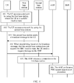
- FIG. 4 is a schematic interaction diagram of still another connection management method according to an embodiment of the present invention. Specifically, as shown in FIG. 4 , the connection management method in this embodiment of the present invention may include the following steps.
- UE accesses a network by using a first base station, where the UE is in an RRC inactive state.
- the UE accesses a network by using a second base station.
- the first base station may be a base station that supports the RRC inactive state.
- the second base station sends a broadcast message to the UE.
- step 401 to step 403 refer to the descriptions of step 301 to step 303 in the embodiment shown in FIG. 3 . Details are not described herein again.
- the UE When determining, based on the broadcast message, that the second base station does not support the RRC inactive state, the UE sends a request message to an AMF
- the UE may receive the broadcast message from the second base station. If determining, based on the broadcast message, that the second base station does not support the RRC inactive state, for example, the broadcast message does not carry capability information indicating that the second base station supports the RRC inactive state, the UE may switch a state of the UE from the RRC inactive state to an idle state, and then send the request message to a core network entity (that is, a first core network entity), for example, the AMF, the request message (that is, a first request message) such as a location update request, an attach request, a registration request, or a service request.
- the UE may send the request message to the second base station, and the second base station forwards the request message to the AMF.
- the UE may send a location update-based registration request such as the registration request to the second base station, and send the registration request to the AMF by using the second base station.
- the request message such as the registration request may include indication information, and the indication information may be used to instruct the UE to switch from the RRC inactive state to the idle state, that is, the request message carries an indication of inactive->idle.
- the request message such as the registration request may further include UE capability information, and the UE capability information may indicate that the UE supports the RRC inactive state. That is, the request message may further carry capability information indicating that the UE supports the RRC inactive state. For example, the UE capability information may be carried in UE network capability in the request message.
- the AMF releases a connection to the first base station.
- the AMF may release the connection to the first base station.
- the AMF performs a PDU session deactivation procedure.
- the request message may be further used to instruct the AMF to perform the PDU session deactivation procedure. Therefore, when receiving the request message, the AMF may further perform the PDU session deactivation procedure, including releasing a connection to an SMF. Further, the SMF may further release a connection to a UPF.
- an AMF corresponding to the first base station may be the same as or different from an AMF corresponding to the second base station.
- AMF corresponding to the first base station may be the same as or different from an AMF corresponding to the second base station.
- the UE may further switch the state of the UE from the RRC inactive state to the idle state to communicate with the second base station that does not support the RRC inactive state.
- the broadcast message triggers to send the request message such as the registration request or the service request to the AMF. Therefore, after receiving the request message, the AMF can release the connection to the first base station and another related connection. In this way, communication is implemented between the UE in the RRC inactive state and a RAN that does not support the RRC inactive state.
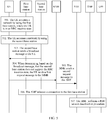
- FIG. 5 is a schematic interaction diagram of still another connection management method according to an embodiment of the present invention. Specifically, as shown in FIG. 5 , the connection management method in this embodiment of the present invention may include the following steps.
- UE accesses a network by using a first base station, where the UE is in an RRC inactive state.
- the UE accesses a network by using a second base station.
- the second base station sends a broadcast message to the UE.
- step 501 to step 503 refer to the descriptions of step 301 to step 303 in the embodiment shown in FIG. 3 . Details are not described herein again.
- the UE When determining, based on the broadcast message, that the second base station does not support the RRC inactive state, the UE sends a first request message to an MME.
- the MME sends a second request message to an AMF
- the AMF releases a connection to the first base station.
- the AMF performs a PDU session deactivation procedure.
- this embodiment of the present invention may be applied to a scenario in which the UE moves from a cell of a 5G base station, that is, the first base station, that supports the RRC inactive state to a cell of a 4G base station, that is, the second base station, that does not support the RRC inactive state.
- the UE may receive the broadcast message from the second base station, and may send the request message (that is, a first request message) such as a location update request, an attach request, a registration request, or a service request to a 4G core network entity MME (the first core network entity) by using the second base station when determining, based on the broadcast message, that the second base station does not support the RRC inactive state.
- a request message such as a location update request, an attach request, a registration request, or a service request
- the UE may send the location update request such as a TAU request or the attach request attach request to the MME by using the second base station.
- the MME may further send the second request message such as the context request to the AMF (a second core network entity).
- the AMF may trigger to release the connection between the AMF and the first base station, and performing the PDU session deactivation procedure, and the like.
- the UE may send the first request message to the AMF (a new AMF, that is, the first core network entity) corresponding to the second base station.
- the new AMF sends the second request message such as a context transfer message to the AMF (an old AMF, that is, the second core network entity) corresponding to the first base station, so that the old AMF may release a connection to the first base station.
- a release process is similar to the process of releasing a connection in the foregoing scenario, and details are not described herein again.
- connection management method in this application. Each embodiment is described with emphasis. For a part that is not described in detail in an embodiment, refer to related descriptions in other embodiments.
- FIG. 6 is a schematic structural diagram of a connection management system according to an embodiment of the present invention.
- the connection management system in this embodiment of the present invention includes UE 1, a first base station 2, a second base station 3, a first core network entity 4, and a second core network entity 5.
- the UE 1 is configured to: access a network by using the first base station 2, where the UE 1 is in a radio resource connection inactive state RRC inactive state; access a network by using the second base station 3, where the second base station 3 does not support the RRC inactive state; and send a first request message to the first core network entity 4 by using the second base station 3.
- the first core network entity 4 is configured to: connect to the first base station 2; receive the first request message sent by the UE 1 by using the second base station 3, where the second base station 3 does not support the RRC inactive state; and release the connection to the first base station 2.
- the second core network entity 5 is configured to: connect to the first base station 2; receive a second request message sent by the second core network entity 4, where the second request message is sent by the first core network entity 4 to the second core network entity 5 when the first core network entity 4 receives the first request message sent by the UE by using the second base station 3, and the second base station 3 does not support the RRC inactive state; and release the connection to the first base station 2.
- the first base station 2 may be a base station corresponding to the network accessed by the UE before the UE moves
- the second base station 3 may be a base station corresponding to the network accessed by the UE after the UE moves.
- the first base station, the second base station, the first core network entity, and the second core network entity in the embodiments of the present invention refer to related descriptions in the embodiments shown in FIG. 2 to FIG. 5 . Details are not described herein again.
- FIG. 7 is a possible schematic structural diagram of the user equipment in the foregoing embodiments.
- user equipment 700 may include a communications unit 701 and a processing unit 702. These units may perform corresponding functions of the UE in the foregoing method example.
- the communications unit 701 is configured to access a network by using a first base station, where the user equipment UE is in a radio resource connection inactive state RRC inactive state.
- the communications unit 701 is further configured to access a network by using a second base station, where the second base station does not support the RRC inactive state.
- the communications unit 701 is further configured to send a first request message to a first core network entity by using the second base station, so that the first core network entity releases a connection to the first base station based on the first request message, or so that the first core network entity sends a second request message to a second core network entity, and the second core network entity releases a connection to the first base station based on the second request message.
- the communications unit 701 is configured to receive a broadcast message sent by the second base station; and the processing unit 702 is configured to determine, based on the broadcast message, whether the second base station supports the RRC inactive state. Further, the communications unit 701 may send the request message to the core network entity by using the second base station when the processing unit 702 determines that the second base station does not support the RRC inactive state.
- the first base station is a base station corresponding to the network accessed by the UE before the UE moves
- the second base station is a base station corresponding to the network accessed by the UE after the UE moves.
- the first core network entity may be a core network entity of the network accessed by the second base station
- the second core network entity may be a core network entity of the network accessed by the first base station
- the processing unit 701 may be further configured to switch a state of the UE from the RRC inactive state to an idle state idle state.
- the first request message may include indication information, and the indication information may be used to instruct the UE to switch from the RRC inactive state to the idle state idle state.
- the first request message may be a location update request, an attach request, a registration request, or a service request.
- the first request message further includes UE capability information, and the UE capability information indicates that the UE supports the RRC inactive state.
- the first base station supports the RRC inactive state.
- the first core network entity may be an MME, an AMF, an SGSN, or the like
- the second core network entity may be an AMF
- unit division is an example, and is merely logical function division. In actual implementation, another division manner may be used.
- Functional units in the embodiments of the present invention may be integrated into one processing unit, or each of the units may exist alone physically, or two or more units are integrated into one unit.
- the integrated unit may be implemented in a form of hardware, or may be implemented in a form of a software functional unit.
- FIG. 8 is another possible schematic structural diagram of the user equipment in the foregoing embodiments.
- the user equipment 800 may include a processing unit 802 and a communications unit 803.
- the processing unit 802 is configured to control and manage an action of the user equipment.
- the processing unit 802 is configured to support the user equipment in performing step 304 in FIG. 3 and/or another process of the technology described in this specification.
- the communications unit 803 is configured to support the user equipment in communicating with other network entities such as the functional units or the network entities shown in FIG. 2 to FIG. 5 .
- the user equipment may further include a storage unit 801, configured to store program code (an operation instruction) and data of the user equipment.
- the processing unit 802 may be a processor or a controller, such as a central processing unit (Central Processing Unit, CPU), a general-purpose processor, a digital signal processor (Digital Signal Processor, DSP), an application-specific integrated circuit (Application-Specific Integrated Circuit, ASIC), a field programmable gate array (Field Programmable Gate Array, FPGA), or another programmable logical device, a transistor logical device, a hardware component, or a combination thereof.
- the processor may implement or execute various example logical blocks, modules, and circuits described with reference to content disclosed in this application.
- the processor may be a combination of processors implementing a computing function, for example, a combination of one or more microprocessors, or a combination of the DSP and a microprocessor.
- the communications unit 803 may be a transceiver, and the storage unit 801 may be a memory.
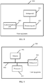
- the user equipment in this embodiment of the present invention may be user equipment shown in FIG. 9 .
- the user equipment 900 may include a processor 902, a transceiver 903, a memory 901, and a bus 904.
- the transceiver 903, the processor 902, and the memory 901 are interconnected by using the bus 904.
- the bus 904 may be a peripheral component interconnect (peripheral component interconnect, PCI for short) bus, or an extended industry standard architecture (extended industry standard architecture, EISA for short) bus, or the like.
- the bus may be classified into an address bus, a data bus, and a control bus, and the like. For ease of representation, only one thick line is used to represent the bus in FIG. 9 , but this does not mean that there is only one bus or only one type of bus.
- the software instruction may include a corresponding software module or a corresponding unit.
- the software module or the unit may be stored in a random access memory (Random Access Memory, RAM), a flash memory, a read-only memory (Read Only Memory, ROM), an erasable programmable read only memory (Erasable Programmable ROM, EPROM), an electrically erasable programmable read only memory (Electrically EPROM, EEPROM), a register, a hard disk, a mobile hard disk, a compact disc read-only memory (CD-ROM), or any other form of storage medium well-known in the art.
- RAM Random Access Memory
- ROM read-only memory
- EPROM erasable programmable read only memory
- Electrically erasable programmable read only memory Electrically erasable programmable read only memory
- EEPROM electrically erasable programmable read only memory
- a storage medium is coupled to a processor, so that the processor can read information from the storage medium or write information into the storage medium.
- the storage medium may be a component of the processor.
- the processor and the storage medium may be located in the ASIC.
- the ASIC may be located in user equipment.
- the processor and the storage medium may be in the user equipment as discrete components.
- FIG. 10 is a possible schematic structural diagram of the core network entity in the foregoing embodiments.
- the core network entity 1000 may include a communications unit 1001 and a processing unit 1002. These units may perform corresponding functions of the core network entity such as the AMF in the foregoing method example.
- the communications unit 1001 is configured to: connect to a first base station, where user equipment UE that accesses a network by using the first base station is in a radio resource connection inactive RRC inactive state.
- the communications unit 1001 is further configured to receive a first request message sent by the UE by using a second base station, or receive a second request message sent by another core network entity, where the second request message is sent by the another core network entity to the core network entity when the another core network entity receives the first request message that is sent by the UE by using the second base station, and the second base station does not support the RRC inactive state.
- the processing unit 1002 is configured to invoke the communications unit 1001 to release a connection to the first base station.
- the first base station may be a base station corresponding to the network accessed by the UE before the UE moves
- the second base station may be a base station corresponding to the network accessed by the UE after the UE moves.
- the first request message includes indication information, and the indication information is used to instruct the UE to switch from the RRC inactive state to an idle state idle state.
- processing unit 1002 is further configured to invoke the communications unit 1001 to perform a protocol data unit session deactivation procedure PDU session deactivation procedure.
- the first request message is a location update request, an attach request, a registration request, or a service request.
- the first request message further includes UE capability information, and the UE capability information indicates that the UE supports the RRC inactive state.
- the first base station supports the RRC inactive state.
- the first core network entity may be an MME, an AMF, an SGSN, or the like
- the second core network entity may be an AMF
- unit division is an example, and is merely logical function division. In actual implementation, another division manner may be used.
- Functional units in the embodiments of the present invention may be integrated into one processing unit, or each of the units may exist alone physically, or two or more units are integrated into one unit.
- the integrated unit may be implemented in a form of hardware, or may be implemented in a form of a software functional unit.
- FIG. 11 is another possible schematic structural diagram of the core network entity in the foregoing embodiments.
- the core network entity 1100 may include a processing unit 1102 and a communications unit 1103.
- the processing unit 1102 may be configured to control and manage an action of the core network entity.
- the processing unit 1102 is configured to support the core network entity in performing step 306 and step 307 in FIG. 3 , and step 405 and step 406 in FIG. 4 , and/or another process of the technology described in this specification.
- the communications unit 1103 is configured to support the core network entity in communicating with other network entities such as the functional units or the network entities shown in FIG. 2 to FIG. 5 .
- the core network entity may further include a storage unit 1101, configured to store program code (an operation instruction) and data of the core network entity.
- the processing unit 1102 may be a processor or a controller, such as a central processing unit (Central Processing Unit, CPU), a general-purpose processor, a digital signal processor (Digital Signal Processor, DSP), an application-specific integrated circuit (Application-Specific Integrated Circuit, ASIC), a field programmable gate array (Field Programmable Gate Array, FPGA), or another programmable logical device, a transistor logical device, a hardware component, or a combination thereof.
- the processor may implement or execute various example logical blocks, modules, and circuits described with reference to content disclosed in this application.
- the processor may be a combination of processors implementing a computing function, for example, a combination of one or more microprocessors, or a combination of the DSP and a microprocessor.
- the communications unit 1103 may be a transceiver.
- the storage unit 1101 may be a memory.
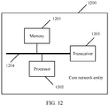
- the core network entity in this embodiment of the present invention may be a core network entity shown in FIG. 12 .
- the core network entity 1200 may include a processor 1202, a transceiver 1203, a memory 1201, and a bus 1204.
- the transceiver 1203, the processor 1202, and the memory 1201 are interconnected by using the bus 1204.
- the bus 1204 may be a peripheral component interconnect (peripheral component interconnect, PCI for short) bus, or an extended industry standard architecture (extended industry standard architecture, EISA for short) bus, or the like.
- the bus may be classified into an address bus, a data bus, and a control bus, and the like. For ease of representation, only one thick line is used to represent the bus in FIG. 12 , but this does not mean that there is only one bus or only one type of bus.
- the software instruction may include a corresponding software module or a corresponding unit.
- the software module or the unit may be stored in a random access memory (Random Access Memory, RAM), a flash memory, a read-only memory (Read Only Memory, ROM), an erasable programmable read only memory (Erasable Programmable ROM, EPROM), an electrically erasable programmable read only memory (Electrically EPROM, EEPROM), a register, a hard disk, a mobile hard disk, a compact disc read-only memory (CD-ROM), or any other form of storage medium well-known in the art.
- RAM Random Access Memory
- ROM read-only memory
- EPROM erasable programmable read only memory
- Electrically erasable programmable read only memory Electrically erasable programmable read only memory
- EEPROM electrically erasable programmable read only memory
- a storage medium is coupled to a processor, so that the processor can read information from the storage medium or write information into the storage medium.
- the storage medium may be a component of the processor.
- the processor and the storage medium may be located in the ASIC.
- the ASIC may be located in the core network entity.
- the processor and the storage medium may be in the core network entity as discrete components.
- steps in the foregoing methods can be implemented by using a hardware integrated logical circuit in the processor, or by using instructions in a form of software.
- the steps of the method disclosed with reference to the embodiments of this application may be directly performed by a hardware processor, or may be performed by using a combination of hardware in the processor and a software module.
- a software module may be located in a mature storage medium in the art, such as a random access memory, a flash memory, a read-only memory, a programmable read-only memory, an electrically erasable programmable memory, or a register.
- the storage medium is located in the memory, and the processor reads information in the memory and completes the steps in the foregoing methods in combination with the hardware in the processor. To avoid repetition, details are not described herein again.
- sequence numbers of the foregoing processes do not mean execution sequences in various embodiments of this application.
- the execution sequences of the processes should be determined based on functions and internal logic of the processes, and should not be construed as any limitation on the implementation processes of the embodiments of the present invention.
- the disclosed system, apparatus, user equipment, core network entity, and method may be implemented in other manners.
- the described apparatus embodiment is merely an example.
- the unit division is merely logical function division and may be other division in actual implementation.
- a plurality of units or components may be combined or integrated into another system, or some features may be ignored or not performed.
- the displayed or discussed mutual coupling or a direct coupling or a communication connection may be implemented through some interfaces.
- An indirect coupling or a communication connection between the apparatus or the unit may be implemented in an electronic form, a mechanical form, or in other forms.
- the units described as separate parts may or may not be physically separate, and parts displayed as units may or may not be physical units, may be located in one position, or may be distributed on a plurality of network units. Some or all of the units may be selected based on actual requirements to achieve the objectives of the solutions of the embodiments.
- the functional units in the embodiments of this application may be integrated into one processing unit, or each of the units may exist alone physically, or two or more units are integrated into one unit.
- All or some of the foregoing embodiments may be implemented by using software, hardware, firmware, or a combination thereof.
- the software is used to implement the embodiments, all or some of the embodiments may be implemented in a form of a computer program product.
- the computer program product includes one or more computer instructions.
- the computer may be a general-purpose computer, a dedicated computer, a computer network, or another programmable apparatus.
- the computer instructions may be stored in a computer-readable storage medium or may be transmitted from a computer-readable storage medium to another computer-readable storage medium.
- the computer instructions may be transmitted from a website, a computer, a server, or a data center to another website, computer, server, or data center in a wired (for example, a coaxial cable, an optical fiber, or a digital subscriber line (DSL)) manner or a wireless (for example, infrared, radio, or microwave) manner.
- the computer-readable storage medium may be any usable medium accessible by a computer, or a data storage device, such as a server and a data center that are integrated by one or more usable media.
- the usable medium may be a magnetic medium (for example, a floppy disk, a hard disk, or a magnetic tape), an optical medium (for example, a DVD), or a semiconductor medium (for example, a solid-state disk Solid State Disk (SSD)), or the like.
- a magnetic medium for example, a floppy disk, a hard disk, or a magnetic tape
- an optical medium for example, a DVD
- a semiconductor medium for example, a solid-state disk Solid State Disk (SSD)
Landscapes
- Engineering & Computer Science (AREA)
- Computer Networks & Wireless Communication (AREA)
- Signal Processing (AREA)
- Mobile Radio Communication Systems (AREA)
Applications Claiming Priority (1)
| Application Number | Priority Date | Filing Date | Title |
|---|---|---|---|
| PCT/CN2017/102808 WO2019056279A1 (zh) | 2017-09-21 | 2017-09-21 | 连接管理方法、用户设备、核心网实体及系统 |
Publications (3)
| Publication Number | Publication Date |
|---|---|
| EP3678449A1 true EP3678449A1 (de) | 2020-07-08 |
| EP3678449A4 EP3678449A4 (de) | 2020-08-26 |
| EP3678449B1 EP3678449B1 (de) | 2022-06-01 |
Family
ID=65809911
Family Applications (1)
| Application Number | Title | Priority Date | Filing Date |
|---|---|---|---|
| EP17925692.0A Active EP3678449B1 (de) | 2017-09-21 | 2017-09-21 | Verbindungsverwaltungsverfahren und benutzervorrichtung |
Country Status (4)
| Country | Link |
|---|---|
| US (1) | US11291069B2 (de) |
| EP (1) | EP3678449B1 (de) |
| CN (1) | CN110431913B (de) |
| WO (1) | WO2019056279A1 (de) |
Families Citing this family (14)
| Publication number | Priority date | Publication date | Assignee | Title |
|---|---|---|---|---|
| JP2019145858A (ja) * | 2016-06-30 | 2019-08-29 | シャープ株式会社 | 端末装置、制御装置、及び通信制御方法 |
| US11889298B2 (en) * | 2017-11-20 | 2024-01-30 | Telefonaktiebolaget Lm Ericsson (Publ) | Security gateway selection in hybrid 4G and 5G networks |
| CN110149728B (zh) * | 2018-02-13 | 2020-09-29 | 华为技术有限公司 | 无线资源控制rrc状态转换的方法、通信装置、网络设备以及计算机存储介质 |
| WO2019165629A1 (zh) * | 2018-03-01 | 2019-09-06 | 华为技术有限公司 | 会话管理方法及装置、通信系统 |
| US12295056B2 (en) * | 2018-12-12 | 2025-05-06 | Comcast Cable Communications, Llc | Network assisted connection |
| US20220264697A1 (en) | 2019-08-07 | 2022-08-18 | Mitsubishi Electric Corporation | Communication system, communication terminal, and network |
| WO2021093182A1 (en) * | 2020-01-22 | 2021-05-20 | Zte Corporation | Techniques to manage access and mobility management function (amf) relocation |
| CN113364721B (zh) * | 2020-03-04 | 2023-06-30 | 大唐移动通信设备有限公司 | 一种sctp连接管理方法及装置 |
| CN113518476B (zh) * | 2020-04-10 | 2025-06-27 | 华为技术有限公司 | 通信方法及装置 |
| CN113973260B (zh) * | 2020-07-22 | 2023-08-01 | 大唐移动通信设备有限公司 | 上行信号定位的方法、通信基站和测量基站及ue |
| EP4184959A4 (de) * | 2020-08-03 | 2024-01-03 | Huawei Technologies Co., Ltd. | Kommunikationsverfahren, -vorrichtung und -system |
| EP3968696B1 (de) * | 2020-09-15 | 2026-02-18 | Nokia Technologies Oy | Ng-basierte kontextfreigabe und datenweiterleitung für multihop-mobilität |
| CN114679797B (zh) * | 2020-12-24 | 2024-12-17 | 大唐移动通信设备有限公司 | 一种用户实体释放方法及基站 |
| US12356297B2 (en) * | 2022-09-19 | 2025-07-08 | Qualcomm Incorporated | Techniques for service states in a service-based wireless system |
Family Cites Families (14)
| Publication number | Priority date | Publication date | Assignee | Title |
|---|---|---|---|---|
| CN102238664B (zh) * | 2010-04-23 | 2014-10-22 | 中兴通讯股份有限公司 | 基站切换中无线资源连接重建拒绝的方法和系统 |
| CN109219098B (zh) * | 2012-08-07 | 2021-09-14 | 华为技术有限公司 | 切换处理方法及基站 |
| US20160088535A1 (en) * | 2013-06-21 | 2016-03-24 | Mitsubishi Electric Corporation | Communication method and communication apparatus |
| WO2015085273A1 (en) | 2013-12-06 | 2015-06-11 | Interdigital Patent Holdings, Inc. | Layered connectivity in wireless systems |
| US11026136B2 (en) * | 2014-03-07 | 2021-06-01 | Parallel Wireless, Inc. | Handovers with simplified network topology |
| US10512106B2 (en) * | 2016-08-12 | 2019-12-17 | Electronics And Telecommunications Research Institute | State transition method based on random access procedure in communication system |
| CA3037476C (en) * | 2016-09-30 | 2023-05-23 | Telefonaktiebolaget Lm Ericsson (Publ) | Core network awareness of user equipment, ue, state |
| WO2018086600A1 (en) * | 2016-11-11 | 2018-05-17 | Chou Chie Ming | Data packet delivery in rrc inactive state |
| EP3560241A4 (de) * | 2016-12-21 | 2020-11-18 | FG Innovation Company Limited | Zustandsübergangsverfahren eines drahtloskommunikationssystems |
| CN106658758A (zh) * | 2017-02-10 | 2017-05-10 | 北京小米移动软件有限公司 | 状态转换方法、状态保持方法、装置及用户设备 |
| US10887761B2 (en) * | 2017-03-01 | 2021-01-05 | Htc Corporation | Device and method for handling a temporary user equipment capability |
| US11184791B2 (en) * | 2017-03-25 | 2021-11-23 | Lg Electronics Inc. | Access control method and device for supporting same |
| JP6954344B2 (ja) * | 2017-04-17 | 2021-10-27 | 富士通株式会社 | 無線端末、基地局、無線通信システム及び無線通信方法 |
| CN109548109B (zh) * | 2017-08-14 | 2021-03-09 | 电信科学技术研究院 | 一种ue和网络状态不匹配的处理方法及装置、存储介质 |
-
2017
- 2017-09-21 US US16/649,377 patent/US11291069B2/en active Active
- 2017-09-21 EP EP17925692.0A patent/EP3678449B1/de active Active
- 2017-09-21 WO PCT/CN2017/102808 patent/WO2019056279A1/zh not_active Ceased
- 2017-09-21 CN CN201780088304.XA patent/CN110431913B/zh active Active
Also Published As
| Publication number | Publication date |
|---|---|
| EP3678449B1 (de) | 2022-06-01 |
| US11291069B2 (en) | 2022-03-29 |
| US20200275515A1 (en) | 2020-08-27 |
| WO2019056279A1 (zh) | 2019-03-28 |
| EP3678449A4 (de) | 2020-08-26 |
| CN110431913B (zh) | 2022-02-25 |
| CN110431913A (zh) | 2019-11-08 |
Similar Documents
| Publication | Publication Date | Title |
|---|---|---|
| EP3678449B1 (de) | Verbindungsverwaltungsverfahren und benutzervorrichtung | |
| US11463981B2 (en) | Location information reporting method and apparatus | |
| US11323920B2 (en) | Handover method, base station, and communications system | |
| EP3565309B1 (de) | Informationsübertragungsverfahren, basisstation und benutzergerät | |
| CN110557777A (zh) | 网络连接的控制方法、终端及存储介质 | |
| RU2755514C2 (ru) | Способ связи, устройство сети доступа и терминал | |
| CN103209444B (zh) | 一种资源释放的方法和装置 | |
| US11483898B2 (en) | Session management method and session management network element | |
| US12010539B2 (en) | Information reporting method, information receiving method, terminal device, and network device | |
| CN113228730A (zh) | 通信方法及装置 | |
| EP3621349B1 (de) | Informationsverarbeitungsverfahren und -vorrichtung | |
| CN107925934B (zh) | 网络指示的处理装置、方法以及通信系统 | |
| EP4120735B1 (de) | Datenübertragungsverfahren, ziel-basisstation und anker-basisstation | |
| CN113727467A (zh) | 一种恢复rrc连接的方法、装置、芯片、设备及存储介质 | |
| CN107889129A (zh) | 一种电话响应的方法和终端 | |
| EP3627891B1 (de) | Kommunikationsverfahren, netzwerkvorrichtung und endgerätevorrichtung | |
| WO2020164470A1 (zh) | 通信方法及其装置、系统 | |
| CN109246773A (zh) | 一种数据传输方法和装置 | |
| KR102239716B1 (ko) | 핸드오버 방법, 코어 네트워크 장치, 액세스 네트워크 장치, 및 단말 장치 | |
| CN116801332A (zh) | 语音业务的处理方法、终端及网络侧设备 | |
| EP4025003B1 (de) | Weiterleitungsverfahren und zugehörige vorrichtung | |
| WO2018214762A1 (zh) | 一种获取寻呼参数的方法及装置 | |
| CN110351785B (zh) | 一种通信方法及其装置 | |
| US10701665B2 (en) | Paging method and device | |
| CN109905894B (zh) | 数据处理方法及网络设备 |
Legal Events
| Date | Code | Title | Description |
|---|---|---|---|
| STAA | Information on the status of an ep patent application or granted ep patent |
Free format text: STATUS: THE INTERNATIONAL PUBLICATION HAS BEEN MADE |
|
| PUAI | Public reference made under article 153(3) epc to a published international application that has entered the european phase |
Free format text: ORIGINAL CODE: 0009012 |
|
| STAA | Information on the status of an ep patent application or granted ep patent |
Free format text: STATUS: REQUEST FOR EXAMINATION WAS MADE |
|
| 17P | Request for examination filed |
Effective date: 20200331 |
|
| AK | Designated contracting states |
Kind code of ref document: A1 Designated state(s): AL AT BE BG CH CY CZ DE DK EE ES FI FR GB GR HR HU IE IS IT LI LT LU LV MC MK MT NL NO PL PT RO RS SE SI SK SM TR |
|
| AX | Request for extension of the european patent |
Extension state: BA ME |
|
| A4 | Supplementary search report drawn up and despatched |
Effective date: 20200729 |
|
| RIC1 | Information provided on ipc code assigned before grant |
Ipc: H04W 76/30 20180101AFI20200723BHEP |
|
| DAV | Request for validation of the european patent (deleted) | ||
| DAX | Request for extension of the european patent (deleted) | ||
| GRAP | Despatch of communication of intention to grant a patent |
Free format text: ORIGINAL CODE: EPIDOSNIGR1 |
|
| STAA | Information on the status of an ep patent application or granted ep patent |
Free format text: STATUS: GRANT OF PATENT IS INTENDED |
|
| INTG | Intention to grant announced |
Effective date: 20220107 |
|
| GRAS | Grant fee paid |
Free format text: ORIGINAL CODE: EPIDOSNIGR3 |
|
| GRAA | (expected) grant |
Free format text: ORIGINAL CODE: 0009210 |
|
| STAA | Information on the status of an ep patent application or granted ep patent |
Free format text: STATUS: THE PATENT HAS BEEN GRANTED |
|
| AK | Designated contracting states |
Kind code of ref document: B1 Designated state(s): AL AT BE BG CH CY CZ DE DK EE ES FI FR GB GR HR HU IE IS IT LI LT LU LV MC MK MT NL NO PL PT RO RS SE SI SK SM TR |
|
| REG | Reference to a national code |
Ref country code: GB Ref legal event code: FG4D |
|
| REG | Reference to a national code |
Ref country code: AT Ref legal event code: REF Ref document number: 1496278 Country of ref document: AT Kind code of ref document: T Effective date: 20220615 Ref country code: CH Ref legal event code: EP |
|
| REG | Reference to a national code |
Ref country code: IE Ref legal event code: FG4D |
|
| REG | Reference to a national code |
Ref country code: DE Ref legal event code: R096 Ref document number: 602017058190 Country of ref document: DE |
|
| REG | Reference to a national code |
Ref country code: LT Ref legal event code: MG9D |
|
| REG | Reference to a national code |
Ref country code: NL Ref legal event code: MP Effective date: 20220601 |
|
| PG25 | Lapsed in a contracting state [announced via postgrant information from national office to epo] |
Ref country code: SE Free format text: LAPSE BECAUSE OF FAILURE TO SUBMIT A TRANSLATION OF THE DESCRIPTION OR TO PAY THE FEE WITHIN THE PRESCRIBED TIME-LIMIT Effective date: 20220601 Ref country code: NO Free format text: LAPSE BECAUSE OF FAILURE TO SUBMIT A TRANSLATION OF THE DESCRIPTION OR TO PAY THE FEE WITHIN THE PRESCRIBED TIME-LIMIT Effective date: 20220901 Ref country code: LT Free format text: LAPSE BECAUSE OF FAILURE TO SUBMIT A TRANSLATION OF THE DESCRIPTION OR TO PAY THE FEE WITHIN THE PRESCRIBED TIME-LIMIT Effective date: 20220601 Ref country code: HR Free format text: LAPSE BECAUSE OF FAILURE TO SUBMIT A TRANSLATION OF THE DESCRIPTION OR TO PAY THE FEE WITHIN THE PRESCRIBED TIME-LIMIT Effective date: 20220601 Ref country code: GR Free format text: LAPSE BECAUSE OF FAILURE TO SUBMIT A TRANSLATION OF THE DESCRIPTION OR TO PAY THE FEE WITHIN THE PRESCRIBED TIME-LIMIT Effective date: 20220902 Ref country code: FI Free format text: LAPSE BECAUSE OF FAILURE TO SUBMIT A TRANSLATION OF THE DESCRIPTION OR TO PAY THE FEE WITHIN THE PRESCRIBED TIME-LIMIT Effective date: 20220601 Ref country code: ES Free format text: LAPSE BECAUSE OF FAILURE TO SUBMIT A TRANSLATION OF THE DESCRIPTION OR TO PAY THE FEE WITHIN THE PRESCRIBED TIME-LIMIT Effective date: 20220601 Ref country code: BG Free format text: LAPSE BECAUSE OF FAILURE TO SUBMIT A TRANSLATION OF THE DESCRIPTION OR TO PAY THE FEE WITHIN THE PRESCRIBED TIME-LIMIT Effective date: 20220901 |
|
| REG | Reference to a national code |
Ref country code: AT Ref legal event code: MK05 Ref document number: 1496278 Country of ref document: AT Kind code of ref document: T Effective date: 20220601 |
|
| PG25 | Lapsed in a contracting state [announced via postgrant information from national office to epo] |
Ref country code: RS Free format text: LAPSE BECAUSE OF FAILURE TO SUBMIT A TRANSLATION OF THE DESCRIPTION OR TO PAY THE FEE WITHIN THE PRESCRIBED TIME-LIMIT Effective date: 20220601 Ref country code: PL Free format text: LAPSE BECAUSE OF FAILURE TO SUBMIT A TRANSLATION OF THE DESCRIPTION OR TO PAY THE FEE WITHIN THE PRESCRIBED TIME-LIMIT Effective date: 20220601 Ref country code: LV Free format text: LAPSE BECAUSE OF FAILURE TO SUBMIT A TRANSLATION OF THE DESCRIPTION OR TO PAY THE FEE WITHIN THE PRESCRIBED TIME-LIMIT Effective date: 20220601 |
|
| PG25 | Lapsed in a contracting state [announced via postgrant information from national office to epo] |
Ref country code: NL Free format text: LAPSE BECAUSE OF FAILURE TO SUBMIT A TRANSLATION OF THE DESCRIPTION OR TO PAY THE FEE WITHIN THE PRESCRIBED TIME-LIMIT Effective date: 20220601 |
|
| PG25 | Lapsed in a contracting state [announced via postgrant information from national office to epo] |
Ref country code: SM Free format text: LAPSE BECAUSE OF FAILURE TO SUBMIT A TRANSLATION OF THE DESCRIPTION OR TO PAY THE FEE WITHIN THE PRESCRIBED TIME-LIMIT Effective date: 20220601 Ref country code: SK Free format text: LAPSE BECAUSE OF FAILURE TO SUBMIT A TRANSLATION OF THE DESCRIPTION OR TO PAY THE FEE WITHIN THE PRESCRIBED TIME-LIMIT Effective date: 20220601 Ref country code: RO Free format text: LAPSE BECAUSE OF FAILURE TO SUBMIT A TRANSLATION OF THE DESCRIPTION OR TO PAY THE FEE WITHIN THE PRESCRIBED TIME-LIMIT Effective date: 20220601 Ref country code: PT Free format text: LAPSE BECAUSE OF FAILURE TO SUBMIT A TRANSLATION OF THE DESCRIPTION OR TO PAY THE FEE WITHIN THE PRESCRIBED TIME-LIMIT Effective date: 20221003 Ref country code: EE Free format text: LAPSE BECAUSE OF FAILURE TO SUBMIT A TRANSLATION OF THE DESCRIPTION OR TO PAY THE FEE WITHIN THE PRESCRIBED TIME-LIMIT Effective date: 20220601 Ref country code: CZ Free format text: LAPSE BECAUSE OF FAILURE TO SUBMIT A TRANSLATION OF THE DESCRIPTION OR TO PAY THE FEE WITHIN THE PRESCRIBED TIME-LIMIT Effective date: 20220601 Ref country code: AT Free format text: LAPSE BECAUSE OF FAILURE TO SUBMIT A TRANSLATION OF THE DESCRIPTION OR TO PAY THE FEE WITHIN THE PRESCRIBED TIME-LIMIT Effective date: 20220601 |
|
| PG25 | Lapsed in a contracting state [announced via postgrant information from national office to epo] |
Ref country code: IS Free format text: LAPSE BECAUSE OF FAILURE TO SUBMIT A TRANSLATION OF THE DESCRIPTION OR TO PAY THE FEE WITHIN THE PRESCRIBED TIME-LIMIT Effective date: 20221001 |
|
| REG | Reference to a national code |
Ref country code: DE Ref legal event code: R097 Ref document number: 602017058190 Country of ref document: DE |
|
| PG25 | Lapsed in a contracting state [announced via postgrant information from national office to epo] |
Ref country code: AL Free format text: LAPSE BECAUSE OF FAILURE TO SUBMIT A TRANSLATION OF THE DESCRIPTION OR TO PAY THE FEE WITHIN THE PRESCRIBED TIME-LIMIT Effective date: 20220601 |
|
| PLBE | No opposition filed within time limit |
Free format text: ORIGINAL CODE: 0009261 |
|
| STAA | Information on the status of an ep patent application or granted ep patent |
Free format text: STATUS: NO OPPOSITION FILED WITHIN TIME LIMIT |
|
| PG25 | Lapsed in a contracting state [announced via postgrant information from national office to epo] |
Ref country code: MC Free format text: LAPSE BECAUSE OF FAILURE TO SUBMIT A TRANSLATION OF THE DESCRIPTION OR TO PAY THE FEE WITHIN THE PRESCRIBED TIME-LIMIT Effective date: 20220601 Ref country code: DK Free format text: LAPSE BECAUSE OF FAILURE TO SUBMIT A TRANSLATION OF THE DESCRIPTION OR TO PAY THE FEE WITHIN THE PRESCRIBED TIME-LIMIT Effective date: 20220601 |
|
| REG | Reference to a national code |
Ref country code: CH Ref legal event code: PL |
|
| 26N | No opposition filed |
Effective date: 20230302 |
|
| GBPC | Gb: european patent ceased through non-payment of renewal fee |
Effective date: 20220921 |
|
| REG | Reference to a national code |
Ref country code: BE Ref legal event code: MM Effective date: 20220930 |
|
| PG25 | Lapsed in a contracting state [announced via postgrant information from national office to epo] |
Ref country code: SI Free format text: LAPSE BECAUSE OF FAILURE TO SUBMIT A TRANSLATION OF THE DESCRIPTION OR TO PAY THE FEE WITHIN THE PRESCRIBED TIME-LIMIT Effective date: 20220601 |
|
| PG25 | Lapsed in a contracting state [announced via postgrant information from national office to epo] |
Ref country code: LU Free format text: LAPSE BECAUSE OF NON-PAYMENT OF DUE FEES Effective date: 20220921 |
|
| PG25 | Lapsed in a contracting state [announced via postgrant information from national office to epo] |
Ref country code: LI Free format text: LAPSE BECAUSE OF NON-PAYMENT OF DUE FEES Effective date: 20220930 Ref country code: IE Free format text: LAPSE BECAUSE OF NON-PAYMENT OF DUE FEES Effective date: 20220921 Ref country code: FR Free format text: LAPSE BECAUSE OF NON-PAYMENT OF DUE FEES Effective date: 20220930 Ref country code: CH Free format text: LAPSE BECAUSE OF NON-PAYMENT OF DUE FEES Effective date: 20220930 |
|
| PG25 | Lapsed in a contracting state [announced via postgrant information from national office to epo] |
Ref country code: BE Free format text: LAPSE BECAUSE OF NON-PAYMENT OF DUE FEES Effective date: 20220930 |
|
| PG25 | Lapsed in a contracting state [announced via postgrant information from national office to epo] |
Ref country code: GB Free format text: LAPSE BECAUSE OF NON-PAYMENT OF DUE FEES Effective date: 20220921 |
|
| PG25 | Lapsed in a contracting state [announced via postgrant information from national office to epo] |
Ref country code: CY Free format text: LAPSE BECAUSE OF FAILURE TO SUBMIT A TRANSLATION OF THE DESCRIPTION OR TO PAY THE FEE WITHIN THE PRESCRIBED TIME-LIMIT Effective date: 20220601 |
|
| PG25 | Lapsed in a contracting state [announced via postgrant information from national office to epo] |
Ref country code: MK Free format text: LAPSE BECAUSE OF FAILURE TO SUBMIT A TRANSLATION OF THE DESCRIPTION OR TO PAY THE FEE WITHIN THE PRESCRIBED TIME-LIMIT Effective date: 20220601 Ref country code: HU Free format text: LAPSE BECAUSE OF FAILURE TO SUBMIT A TRANSLATION OF THE DESCRIPTION OR TO PAY THE FEE WITHIN THE PRESCRIBED TIME-LIMIT; INVALID AB INITIO Effective date: 20170921 |
|
| PG25 | Lapsed in a contracting state [announced via postgrant information from national office to epo] |
Ref country code: MT Free format text: LAPSE BECAUSE OF FAILURE TO SUBMIT A TRANSLATION OF THE DESCRIPTION OR TO PAY THE FEE WITHIN THE PRESCRIBED TIME-LIMIT Effective date: 20220601 |
|
| PG25 | Lapsed in a contracting state [announced via postgrant information from national office to epo] |
Ref country code: BG Free format text: LAPSE BECAUSE OF FAILURE TO SUBMIT A TRANSLATION OF THE DESCRIPTION OR TO PAY THE FEE WITHIN THE PRESCRIBED TIME-LIMIT Effective date: 20220601 |
|
| PG25 | Lapsed in a contracting state [announced via postgrant information from national office to epo] |
Ref country code: BG Free format text: LAPSE BECAUSE OF FAILURE TO SUBMIT A TRANSLATION OF THE DESCRIPTION OR TO PAY THE FEE WITHIN THE PRESCRIBED TIME-LIMIT Effective date: 20220601 |
|
| PGFP | Annual fee paid to national office [announced via postgrant information from national office to epo] |
Ref country code: DE Payment date: 20250730 Year of fee payment: 9 |
|
| PGFP | Annual fee paid to national office [announced via postgrant information from national office to epo] |
Ref country code: IT Payment date: 20250825 Year of fee payment: 9 |
|
| PG25 | Lapsed in a contracting state [announced via postgrant information from national office to epo] |
Ref country code: TR Free format text: LAPSE BECAUSE OF FAILURE TO SUBMIT A TRANSLATION OF THE DESCRIPTION OR TO PAY THE FEE WITHIN THE PRESCRIBED TIME-LIMIT Effective date: 20220601 |