EP3678843B1 - Vorrichtung und verfahren zum erwärmen von kunststoffvorformlingen mit steuerbarer heizleistung - Google Patents
Vorrichtung und verfahren zum erwärmen von kunststoffvorformlingen mit steuerbarer heizleistung Download PDFInfo
- Publication number
- EP3678843B1 EP3678843B1 EP18765887.7A EP18765887A EP3678843B1 EP 3678843 B1 EP3678843 B1 EP 3678843B1 EP 18765887 A EP18765887 A EP 18765887A EP 3678843 B1 EP3678843 B1 EP 3678843B1
- Authority
- EP
- European Patent Office
- Prior art keywords
- heating
- plastic preforms
- heating elements
- temperature
- elements
- Prior art date
- Legal status (The legal status is an assumption and is not a legal conclusion. Google has not performed a legal analysis and makes no representation as to the accuracy of the status listed.)
- Active
Links
Images


Classifications
-
- B—PERFORMING OPERATIONS; TRANSPORTING
- B29—WORKING OF PLASTICS; WORKING OF SUBSTANCES IN A PLASTIC STATE IN GENERAL
- B29C—SHAPING OR JOINING OF PLASTICS; SHAPING OF MATERIAL IN A PLASTIC STATE, NOT OTHERWISE PROVIDED FOR; AFTER-TREATMENT OF THE SHAPED PRODUCTS, e.g. REPAIRING
- B29C49/00—Blow-moulding, i.e. blowing a preform or parison to a desired shape within a mould; Apparatus therefor
- B29C49/42—Component parts, details or accessories; Auxiliary operations
- B29C49/64—Heating or cooling preforms, parisons or blown articles
- B29C49/6409—Thermal conditioning of preforms
- B29C49/6436—Thermal conditioning of preforms characterised by temperature differential
-
- B—PERFORMING OPERATIONS; TRANSPORTING
- B29—WORKING OF PLASTICS; WORKING OF SUBSTANCES IN A PLASTIC STATE IN GENERAL
- B29C—SHAPING OR JOINING OF PLASTICS; SHAPING OF MATERIAL IN A PLASTIC STATE, NOT OTHERWISE PROVIDED FOR; AFTER-TREATMENT OF THE SHAPED PRODUCTS, e.g. REPAIRING
- B29C49/00—Blow-moulding, i.e. blowing a preform or parison to a desired shape within a mould; Apparatus therefor
- B29C49/02—Combined blow-moulding and manufacture of the preform or the parison
- B29C49/06—Injection blow-moulding
-
- B—PERFORMING OPERATIONS; TRANSPORTING
- B29—WORKING OF PLASTICS; WORKING OF SUBSTANCES IN A PLASTIC STATE IN GENERAL
- B29C—SHAPING OR JOINING OF PLASTICS; SHAPING OF MATERIAL IN A PLASTIC STATE, NOT OTHERWISE PROVIDED FOR; AFTER-TREATMENT OF THE SHAPED PRODUCTS, e.g. REPAIRING
- B29C49/00—Blow-moulding, i.e. blowing a preform or parison to a desired shape within a mould; Apparatus therefor
- B29C49/08—Biaxial stretching during blow-moulding
-
- B—PERFORMING OPERATIONS; TRANSPORTING
- B29—WORKING OF PLASTICS; WORKING OF SUBSTANCES IN A PLASTIC STATE IN GENERAL
- B29C—SHAPING OR JOINING OF PLASTICS; SHAPING OF MATERIAL IN A PLASTIC STATE, NOT OTHERWISE PROVIDED FOR; AFTER-TREATMENT OF THE SHAPED PRODUCTS, e.g. REPAIRING
- B29C49/00—Blow-moulding, i.e. blowing a preform or parison to a desired shape within a mould; Apparatus therefor
- B29C49/08—Biaxial stretching during blow-moulding
- B29C49/10—Biaxial stretching during blow-moulding using mechanical means for prestretching
- B29C49/122—Drive means therefor
- B29C49/123—Electric drives, e.g. linear motors
-
- B—PERFORMING OPERATIONS; TRANSPORTING
- B29—WORKING OF PLASTICS; WORKING OF SUBSTANCES IN A PLASTIC STATE IN GENERAL
- B29C—SHAPING OR JOINING OF PLASTICS; SHAPING OF MATERIAL IN A PLASTIC STATE, NOT OTHERWISE PROVIDED FOR; AFTER-TREATMENT OF THE SHAPED PRODUCTS, e.g. REPAIRING
- B29C49/00—Blow-moulding, i.e. blowing a preform or parison to a desired shape within a mould; Apparatus therefor
- B29C49/28—Blow-moulding apparatus
- B29C49/30—Blow-moulding apparatus having movable moulds or mould parts
- B29C49/36—Blow-moulding apparatus having movable moulds or mould parts rotatable about one axis
-
- B—PERFORMING OPERATIONS; TRANSPORTING
- B29—WORKING OF PLASTICS; WORKING OF SUBSTANCES IN A PLASTIC STATE IN GENERAL
- B29C—SHAPING OR JOINING OF PLASTICS; SHAPING OF MATERIAL IN A PLASTIC STATE, NOT OTHERWISE PROVIDED FOR; AFTER-TREATMENT OF THE SHAPED PRODUCTS, e.g. REPAIRING
- B29C49/00—Blow-moulding, i.e. blowing a preform or parison to a desired shape within a mould; Apparatus therefor
- B29C49/02—Combined blow-moulding and manufacture of the preform or the parison
- B29C2049/023—Combined blow-moulding and manufacture of the preform or the parison using inherent heat of the preform, i.e. 1 step blow moulding
-
- B—PERFORMING OPERATIONS; TRANSPORTING
- B29—WORKING OF PLASTICS; WORKING OF SUBSTANCES IN A PLASTIC STATE IN GENERAL
- B29C—SHAPING OR JOINING OF PLASTICS; SHAPING OF MATERIAL IN A PLASTIC STATE, NOT OTHERWISE PROVIDED FOR; AFTER-TREATMENT OF THE SHAPED PRODUCTS, e.g. REPAIRING
- B29C49/00—Blow-moulding, i.e. blowing a preform or parison to a desired shape within a mould; Apparatus therefor
- B29C49/20—Blow-moulding, i.e. blowing a preform or parison to a desired shape within a mould; Apparatus therefor of articles having inserts or reinforcements ; Handling of inserts or reinforcements
- B29C2049/2095—Means for preparing or treating the inserts, e.g. cutting, deforming, heating, cooling or applying adhesives
-
- B—PERFORMING OPERATIONS; TRANSPORTING
- B29—WORKING OF PLASTICS; WORKING OF SUBSTANCES IN A PLASTIC STATE IN GENERAL
- B29C—SHAPING OR JOINING OF PLASTICS; SHAPING OF MATERIAL IN A PLASTIC STATE, NOT OTHERWISE PROVIDED FOR; AFTER-TREATMENT OF THE SHAPED PRODUCTS, e.g. REPAIRING
- B29C49/00—Blow-moulding, i.e. blowing a preform or parison to a desired shape within a mould; Apparatus therefor
- B29C49/42—Component parts, details or accessories; Auxiliary operations
- B29C49/46—Component parts, details or accessories; Auxiliary operations characterised by using particular environment or blow fluids other than air
- B29C2049/4673—Environments
- B29C2049/4697—Clean room
-
- B—PERFORMING OPERATIONS; TRANSPORTING
- B29—WORKING OF PLASTICS; WORKING OF SUBSTANCES IN A PLASTIC STATE IN GENERAL
- B29C—SHAPING OR JOINING OF PLASTICS; SHAPING OF MATERIAL IN A PLASTIC STATE, NOT OTHERWISE PROVIDED FOR; AFTER-TREATMENT OF THE SHAPED PRODUCTS, e.g. REPAIRING
- B29C49/00—Blow-moulding, i.e. blowing a preform or parison to a desired shape within a mould; Apparatus therefor
- B29C49/42—Component parts, details or accessories; Auxiliary operations
- B29C49/78—Measuring, controlling or regulating
- B29C49/786—Temperature
- B29C2049/7861—Temperature of the preform
-
- B—PERFORMING OPERATIONS; TRANSPORTING
- B29—WORKING OF PLASTICS; WORKING OF SUBSTANCES IN A PLASTIC STATE IN GENERAL
- B29C—SHAPING OR JOINING OF PLASTICS; SHAPING OF MATERIAL IN A PLASTIC STATE, NOT OTHERWISE PROVIDED FOR; AFTER-TREATMENT OF THE SHAPED PRODUCTS, e.g. REPAIRING
- B29C49/00—Blow-moulding, i.e. blowing a preform or parison to a desired shape within a mould; Apparatus therefor
- B29C49/42—Component parts, details or accessories; Auxiliary operations
- B29C49/78—Measuring, controlling or regulating
- B29C49/786—Temperature
- B29C2049/7867—Temperature of the heating or cooling means
- B29C2049/78675—Temperature of the heating or cooling means of the heating means
-
- B—PERFORMING OPERATIONS; TRANSPORTING
- B29—WORKING OF PLASTICS; WORKING OF SUBSTANCES IN A PLASTIC STATE IN GENERAL
- B29C—SHAPING OR JOINING OF PLASTICS; SHAPING OF MATERIAL IN A PLASTIC STATE, NOT OTHERWISE PROVIDED FOR; AFTER-TREATMENT OF THE SHAPED PRODUCTS, e.g. REPAIRING
- B29C49/00—Blow-moulding, i.e. blowing a preform or parison to a desired shape within a mould; Apparatus therefor
- B29C49/42—Component parts, details or accessories; Auxiliary operations
- B29C49/78—Measuring, controlling or regulating
- B29C2049/788—Controller type or interface
- B29C2049/7882—Control interface, e.g. display
-
- B—PERFORMING OPERATIONS; TRANSPORTING
- B29—WORKING OF PLASTICS; WORKING OF SUBSTANCES IN A PLASTIC STATE IN GENERAL
- B29C—SHAPING OR JOINING OF PLASTICS; SHAPING OF MATERIAL IN A PLASTIC STATE, NOT OTHERWISE PROVIDED FOR; AFTER-TREATMENT OF THE SHAPED PRODUCTS, e.g. REPAIRING
- B29C49/00—Blow-moulding, i.e. blowing a preform or parison to a desired shape within a mould; Apparatus therefor
- B29C49/42—Component parts, details or accessories; Auxiliary operations
- B29C49/64—Heating or cooling preforms, parisons or blown articles
- B29C49/6409—Thermal conditioning of preforms
- B29C49/6436—Thermal conditioning of preforms characterised by temperature differential
- B29C49/6445—Thermal conditioning of preforms characterised by temperature differential through the preform length
-
- B—PERFORMING OPERATIONS; TRANSPORTING
- B29—WORKING OF PLASTICS; WORKING OF SUBSTANCES IN A PLASTIC STATE IN GENERAL
- B29C—SHAPING OR JOINING OF PLASTICS; SHAPING OF MATERIAL IN A PLASTIC STATE, NOT OTHERWISE PROVIDED FOR; AFTER-TREATMENT OF THE SHAPED PRODUCTS, e.g. REPAIRING
- B29C49/00—Blow-moulding, i.e. blowing a preform or parison to a desired shape within a mould; Apparatus therefor
- B29C49/42—Component parts, details or accessories; Auxiliary operations
- B29C49/78—Measuring, controlling or regulating
- B29C49/786—Temperature
-
- B—PERFORMING OPERATIONS; TRANSPORTING
- B29—WORKING OF PLASTICS; WORKING OF SUBSTANCES IN A PLASTIC STATE IN GENERAL
- B29L—INDEXING SCHEME ASSOCIATED WITH SUBCLASS B29C, RELATING TO PARTICULAR ARTICLES
- B29L2031/00—Other particular articles
- B29L2031/712—Containers; Packaging elements or accessories, Packages
- B29L2031/7158—Bottles
Definitions
- the present invention relates to a device and a method for heating plastic preforms.
- plastic preforms In the beverage manufacturing industry, it is common for plastic preforms to be heated first and then formed into plastic containers such as plastic bottles by means of a forming process, such as a stretch blow molding process. In this case, even when heating the plastic preforms, a profiling of the heating can usually be carried out, for example in a longitudinal direction of the plastic preforms.
- such heating devices of stretch blow molding machines usually have a certain number of heating boxes that are arranged one behind the other in the direction of travel of the plastic preforms.
- Each of these heating boxes preferably has a large number of heating devices arranged one above the other, such as lamps, which ensure profiling as the plastic preforms pass by, i.e. individual areas or layers of the plastic preforms (which lie one above the other in the longitudinal direction of the plastic preforms) can be tempered or heated to different temperatures. This tempering can be used to control the material distribution during the subsequent stretch blow molding process.
- each heating element for example each lamp
- a lamp matrix can be switched on individually, where heating boxes are shown on a user interface in the x-direction and the individual lamps of a heating box in the y-direction.
- the user can specifically select individual heating elements, such as heating lamps.
- a certain energy input in a layer is determined both by the number of lamps switched on in a layer and by a percentage value with which all lamps in, for example, a layer can be weighted again.
- the internally known devices of the applicant also include a higher-level temperature controller, the control variable of which tracks the entire lamp field, i.e. in both the x and y directions. For the lamps in a certain layer, the following lamp power is therefore obtained:
- P Lamp_y P nenn_y * % Temperature controller * % Layer_y
- y layer denotes the individual layers mentioned above, for example values from 1 to 9.
- E y P nenn_y * % Temperature controller * % Layer_y * ⁇ A X * t
- x denotes the respective heating device, or more precisely the respective heating section, and is counted from 1 to n
- y denotes the area or layer
- t the dwell time in front of an individual heating section (this means that a specific heating section can preferably be assigned to a heating device).
- E Y denotes the amount of energy emitted by a heating device as a plastic preform moves past, or the energy that is radiated onto the respective layer of the plastic preform. In order to determine the energy input into the individual plastic preform from this, the proportion of the power effective for heating an individual plastic preform must also be taken into account.
- This lamp matrix described here therefore requires a lot of operator input, so that process identification is complex and can sometimes only be carried out by specially trained personnel.
- variations are often possible. For example, if only a few lamps are switched on in a shift, it would be possible to distribute the remaining lamps over the entire length of the furnace or to switch them on at the beginning or end. This in turn makes process identification much more difficult and also leads to different process engineers coming up with different recipes.
- US2010/314806 A1 discloses a method and a device for blow molding containers, in which a preform made of a thermoplastic material is first subjected to thermal conditioning in the region of a heating section along a transport path. The preform is then transferred into the container within a blow mold by the action of blowing pressure.
- the thermal conditioning of the preforms is carried out by a number of radiant heaters arranged one above the other. The radiant heaters are activated during the heating profile and activated in standby mode according to a second heating profile.
- EN 10 2009 047541 A1 discloses a furnace for stretch blow molding preforms into plastic containers, with a heating wheel on which several heating modules are arranged for heating one preform each. Furthermore, this discloses a control device for controlling the heating modules on the basis of the measured temperature.
- AT 521 U1 relates to a method for adjusting process parameters in the production of hollow bodies from tubular, thermoplastic preforms, in particular in a stretch blow molding machine, wherein the preforms are heated in a heating device.
- EP 2390082 A1 discloses a method for controlling and/or regulating the temperature of a heating device for preforms in a blow molding or stretch blow molding process.
- the tempering process comprises at least two separate, successive heating stages, with the first heating stage providing an approximately uniform basic temperature for the entire preform.
- DE 102009015519 A1 discloses an apparatus for forming plastic preforms into plastic containers with a plurality of blowing stations and a plurality of heating devices arranged along the transport path of each container upstream of the blowing stations.
- WO 2012/172250 A1 discloses a method for heating a plastic preform, in which a measurement of the wall temperature of the preform is carried out while the preforms are exposed to radiation.
- DE10 2009 026259 A1 discloses a device and a method for preheating preforms. This comprises a control unit with which the radiators can be individually controlled and regulated.
- the US 2006/157896 A1 discloses a method and apparatus for producing bottles and preforms with a crystalline neck.
- EN 10 2015 122106 A1 discloses a method for heating plastic preforms, wherein the plastic preforms are transported by means of a transport device along a predetermined transport path and are heated during this transport by at least one first electrically operated heating device, wherein during or after the heating of the plastic preforms a temperature of the plastic preforms is detected by means of a first measuring device.
- the US 2007/066714 A1 discloses a polyester polymer and copolymer compositions containing carbon-coated iron particles.
- the EP 2390 082 B1 discloses an apparatus and a method for controlling and/or regulating the temperature of a heating device for preforms.
- the present invention is therefore based on the object of providing a device and a method which is particularly easier to operate. This object is achieved according to the invention by the subject matter of the independent patent claims. Advantageous embodiments and further developments are the subject matter of the subclaims.
- a device for heating plastic preforms has a transport device which transports the plastic preforms along a predetermined transport path.
- the transport device has a plurality of holding devices for holding the plastic preforms.
- at least one first heating section is provided, which is arranged along this transport path, and at least one second heating section, which is also arranged along this transport path downstream of the first heating section.
- the heating sections each have a plurality of independently controllable heating elements which heat of the plastic preforms in several heating zones lying one above the other in the longitudinal direction of the plastic preforms with a temperature profile that changes in a longitudinal direction of the plastic preforms.
- the device has a control device for controlling this heating section.
- the device has an input device via which a user can specify at least one target value for a heating process and/or the individual heating zones, and a processor device and/or a control device is provided which controls the individual heating elements taking this target value into account.
- the invention suggests that the user only sets a target profile or, for example, a temperature specification, and the processor device then automatically calculates in which layers, whether and how many heating elements, for example heating lamps, are to be activated.
- the invention is based on the fact that a certain energy input in a layer also results from the number of lamps switched on in a layer, for example multiplied by the percentage value of the layering. This means that the same result could also be achieved by switching off lamps or by reducing a percentage value. This means that the individual controls for the plastic preforms are no longer specified as before, but rather a target value for the heating to be achieved.
- the setpoint values or the predefinable setpoint values are setpoint values that are characteristic of an absolute or relative (in particular percentage) zone output and/or these setpoint values are absolute or relative (percentage) zone outputs or setpoint values that are characteristic of these zone outputs.
- the device has a processor device which is suitable and intended to determine the optimum setpoint values of the individual heating elements for the longest possible service life of the lamps.
- This The processor device can have an algorithm that performs corresponding calculations.
- the processor device and/or an algorithm determines the optimal (and/or optimized) setpoint values of the individual heating elements for a heating profile that is as energy-efficient as possible.
- the input device enables the input of a large number of target values for the individual heating zones, preferably those zones that serve to heat the individual areas or layers of the plastic preforms.
- the input device can thus be a keyboard or a touchscreen via which the user can specify the target values. It is possible that the target values are a temperature (in particular zone-dependent) of the plastic preforms. This can preferably be entered continuously.
- the setpoints may be performance values for an entire area- or zone-dependent heating output.
- the heating device is advantageously an infrared heating device, i.e. the heating sections are in particular infrared heating sections.
- the heating elements are lamps which are arranged one above the other in particular in a longitudinal direction of the plastic preforms. These heating elements or lamps preferably also extend in the transport direction of the plastic preforms.
- the device has a rotating device for rotating the plastic preforms with respect to their longitudinal direction.
- microwave heating elements could also be provided.
- the device has a device for forming plastic preforms arranged downstream of the heating device.
- the device for forming plastic preforms into plastic containers is preferably a blow molding machine.
- the flowable medium is preferably under pressure.
- the device has a blow nozzle which can be placed in a sealing manner against an opening of the plastic preforms in order to expand the plastic preforms with liquid or gaseous medium.
- a valve arrangement is preferably also provided which controls the supply of blowing air to the plastic preforms.
- the blow molding machine is preferably a stretch blow molding machine, which means that the preforms are stretched in the longitudinal direction using a stretching rod before and/or during expansion.
- the blow molding stations each have stretching rods that can be inserted into the plastic preforms and stretch the plastic preforms in their longitudinal direction.
- the stretching rods preferably have an electric drive.
- a plurality of blowing stations are arranged on a common movable carrier.
- This carrier is in particular a rotatable carrier.
- the blowing stations each have a blow molding device, which preferably forms a cavity within which the plastic preforms can be expanded to form the plastic containers.
- These blow molding devices are preferably designed in several parts and have two blow mold halves and a base mold. These blow mold halves are preferably arranged detachably on a mold carrier shell or on the blow mold carriers.
- the blow mold carriers can be pivoted relative to one another in order to open and close the blow molding devices.
- the blow mold carrier has locking mechanisms in order to lock the mold halves against one another during the blowing process.
- the blow molding machine or the carrier and the blow mold arrangements are arranged within a clean room, which separates the blow molding machine from a non-sterile environment.
- Drive devices for closing, locking and/or opening the blow molds are preferably arranged outside the clean room.
- the blow molding devices are preferably transported within the clean room.
- the clean room is preferably delimited by several walls.
- the clean room is preferably delimited by at least one stationary wall and a wall moving opposite this stationary wall.
- the clean room delimits the blow molds in particular from a non-sterile environment.
- the clean room is advantageously designed in a ring or torus shape around the blow molding stations or forming stations and/or the transport path of the plastic containers.
- the processor device and/or the control device or the apparatus also allows a change in the transport speed of the plastic preforms.
- the heating sections are arranged stationary and the plastic preforms are transported past these heating sections or the heating elements.
- the device has a measuring device for measuring the power of the individual heating elements.
- the input device enables the input of a large number of target values for the individual heating zones or layers. For example, the user can specify the temperature the plastic preforms should have in certain layers.
- the device has a plurality of heating sections that are arranged one behind the other along the transport path of the plastic preforms. For example, more than four, preferably more than eight, preferably more than ten, preferably more than twelve such heating sections can be provided. However, the device advantageously has fewer than 50, preferably fewer than 40 and particularly preferably fewer than 30 such heating sections.
- the device has at least two heating elements arranged one above the other in the longitudinal direction, preferably at least three, preferably at least four and particularly preferably at least five.
- the heating section has fewer than 15 heating elements arranged one above the other in the longitudinal direction of the plastic preforms, preferably less than 14, preferably less than 13 and particularly preferably less than twelve.
- each heating section can be controlled independently of one another.
- the individual heating sections being shown in an x-direction of this matrix, for example, and the heating elements (of each individual heating section) arranged one above the other being shown in the y-direction.
- the device has a temperature measuring device which measures an actual temperature of the plastic preforms.
- the processor device preferably controls the heating of the plastic preforms based on this measured temperature.
- the device also has a control device which controls at least the first heating element depending on a temperature of the plastic preforms measured by the temperature measuring device. It is possible for this temperature measuring device to be arranged in the area of an inlet of the plastic preforms in front of the device. However, it would also be possible for such a temperature measuring device to be arranged in a central area of the heating device.
- the control device controls a power of the heating elements between at least two limit values.
- the respective heating elements for example lamps
- the control device is designed in such a way that it selects how many lamps are to be operated in order to achieve these favorable operating conditions. It is thus provided that the individual heating elements, for example lamps, are operated under ideal conditions in order to achieve energy savings.
- the lamps are preferably operated in a power range that is above 30% of their nominal power, preferably above 40% of their nominal power and particularly preferably above 50% of their nominal power.
- the heating elements or lamps are particularly preferably operated in a power range which is below 90% and particularly preferably below 80% of the rated power.
- the device has a second temperature measuring device which serves to measure a temperature of the plastic preforms. It is possible to provide this second temperature measuring device, for example, at an outlet of the heating section or the oven. In this way, it can be determined to which temperatures the plastic preforms are heated. It can also be determined on the basis of the respective temperature difference how and, if applicable, with what power the individual heating elements are to be operated.
- heating sections or groups of heating sections that are to be activated can be selected.
- the user can choose whether, for example, heating sections should be activated at the beginning of the transport section or at the end of the transport section. It would also be possible for the user to choose, for example, that only certain heating sections should be activated. It is also possible for individual heating elements of the respective heating sections to be activated or deactivated. For example, only the top elements.
- the control described here can also prevent the risk of the lamps or heating elements leaving the optimal operating point (both upwards and downwards), which can have a significant impact on the service life of the lamps.
- An optimal combination of parameters (in particular the number and position of the lamps switched on and the layering of the lamps) is automated.
- An algorithm is preferably provided that takes into account that the lamp power is in a certain range so that the individual heating elements or lamps are operated at optimal operating temperatures.
- a base temperature or the temperature of the glass bulb of the lamp can be taken into account.
- the base temperature of the lamp can be in a certain temperature range between 150°C and 450°C, particularly preferably in a temperature range between 150°C and 350°C.
- a temperature of the glass bulb can preferably be below 900°C.
- a power control device which controls the lamp power also taking into account the operating temperature of the lamps.
- the parameters percentage control value and number of heating elements switched on are coordinated with each other taking into account the range and the operator input.
- further parameters can be the positions of the switched-on lamps (ie the individual lamps of the heating sections) along the length of the furnace.
- the switched-on lamps could be evenly distributed along the length of the furnace, but it would also be possible for the lamps to be positioned preferentially at the furnace inlet and preferably at the Oven outlet can be switched on.
- These parameters can also be mapped using the oven model.
- Decision variables can include, for example, the presence and size of intermediate modules, such as sterilization modules or modules that allow the plastic preforms to be heated differently in the circumferential direction.
- Other possible parameters can be the machine speed, the equalization time or the weight of the plastic preforms. The procedure described here makes it easier to find the process overall and the service life of the lamps can also be increased.
- a target temperature of the plastic preforms and in particular a zone-based target temperature of the plastic preforms is used as a control variable.
- the present invention is further directed to a method for heating plastic preforms, wherein the plastic preforms are transported along a predetermined transport path using a transport device, and wherein the transport device has a plurality of holding elements for holding the plastic preforms, and wherein at least one first heating section is arranged along this transport path, as well as at least one second heating section, which is also arranged along this transport path and downstream of the first heating section.
- These heating sections preferably heat the plastic preforms, wherein the heating sections each have a plurality of independently controllable heating elements which heat the plastic preforms in a plurality of heating zones lying one above the other in the longitudinal direction of the plastic preforms with a temperature profile that changes in a longitudinal direction of the plastic preforms, wherein a control device controls these heating sections.
- heating device can also be used instead of the term heating section, since, as mentioned above, a specific heating section can be assigned to a specific heating device.
- the device has an input device via which the user can at least partially specify a target value for the heating process and a processor device controls - preferably automatically - the individual heating elements taking this target value into account.
- a target value for the heating process is preferably a target value and in particular an optimal and/or optimized target value of a lamp power (or a power of the respective heating elements) and/or a setpoint that is characteristic for this lamp power.
- a target value for example a desired temperature at the outlet of the oven.
- this target value not to be set by the user, but by a downstream control device, for example a downstream blow molding machine, which controls the heating device accordingly depending on the applicable process parameters.
- the predeterminable target values are the energies introduced into the plastic preform per zone and/or the temperatures of the plastic preforms to be achieved per zone.
- the performances are preferably determined taking into account the energies to be introduced or the temperatures of the plastic preforms to be achieved per zone. It is pointed out that in the context of this application, the terms preform and plastic preform are used synonymously.
- a temperature of the plastic preforms is measured at least temporarily and preferably at least once.
- an actual temperature of the plastic preforms is measured, particularly preferably at an outlet of the heating device.
- the individual heating sections and in particular the individual heating elements are controlled taking into account a measured actual temperature of the plastic preforms.
- the temperature of the plastic preforms is measured without contact.
- the temperature of the plastic preforms is also measured depending on a longitudinal direction of the plastic preforms.
- at least one temperature measuring device is therefore provided, which also allows the temperature of the plastic preforms to be determined depending on the zone or area.
- Figure 1 shows a device 1 according to the invention for heating plastic preforms 10.
- the plastic preforms 10 are fed to the actual heating device via a feed device 12, such as a single-cycle star.
- This heating device has a transport device 2 on which a plurality of holding elements 22 are arranged. These holding elements 22 also allow the plastic preforms to be rotated with respect to their longitudinal axes.
- the plastic preforms are guided along a transport path P and then transferred to another transport device 30.
- a forming device for forming plastic preforms into plastic containers can be connected to the transport device 30.
- the reference numerals 4 refer to a plurality of heating sections arranged along a lower branch of the transport path and the reference numerals 14 refer to a plurality of heating sections arranged along an upper branch of the transport device.
- the reference number 6 designates a first temperature measuring device, which is arranged here at a furnace inlet.
- the reference number 26 designates a second temperature measuring device, which is arranged at the end of the transport path of the plastic preforms.
- a further temperature measuring device could also be provided, for example, in a deflection area in which the plastic preforms are transferred from the lower branch to the upper branch.
- the reference number 16 designates an input device via which the user can specify which heating of the plastic preforms is desired.
- This input device can, for example, have a touchscreen or the like.
- the reference number 18 designates a processor device which determines a control of the individual heating sections on the basis of the user inputs.
- the device has a control device 20 which is suitable and intended to control the individual heating sections 4 and 14.
- FIG. 2 shows a schematic representation of a heating section 4, 14. This has a plurality of heating elements arranged one above the other in the longitudinal direction L of the plastic preforms. These heating elements are designed here as radiators 42, 44, 46, 48, 50, 52, 54, 56 and 58. These individual radiators can be operated independently of one another and in particular can also be controlled independently of the control device 20.
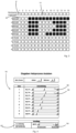
- FIG. 3 shows a representation of an array from the applicant's internal prior art.
- a large number of heating sections 4 and 14 are shown. These each have heating elements 42, 44, 46, 48, 50, 52, 54, 56 and 58 arranged one above the other in the y-direction.
- These heating elements can be activated individually and in particular can also be activated individually with the powers 90%, 85%, etc. indicated on the left edge.
- the bottom four heating elements are not activated, which may be due to the fact that shorter plastic preforms are heated that do not extend into the area of these lower heating elements.
- Figure 4 shows a representation of an input device through which the user can specify heating settings.
- the individual zones 1 - 9 are listed here, which correspond to the respective heating elements 42, 44, 46, 48, 50, 52, 54, 56 and 58. recognizes that the user can select a zone output in percent using input elements 82 and 84.
- the control device or the processor device then automatically determines which of the individual heating elements or heating sections are activated in order to achieve the desired heating or zone output in the most favorable manner possible.
- an input element 62 can be provided, via which the user can select whether he wants heating to be right- or left-aligned, i.e. in which areas of the transport path the plastic preforms should be heated.
- an input element 64 the user can also specify in which area of the heating device the heating should take place.
- Right-aligned heating means that the energy is introduced as late as possible (this is advantageous, for example, for thin-walled preforms so that they do not overheat).
- Left-aligned heating means that the energy is introduced early and then there is enough equalization time for the temperature to spread across the thickness of the plastic preform wall (this may be necessary for thick-walled plastic preforms or colored plastic preforms).
- Figure 5a shows a design in which heating is to take place in particular in an end region of the heating section. It can be seen here that the heating boxes or heating sections 9 - 20 are activated in particular. In this case, it was therefore desired that the plastic preforms be heated in particular towards the end of their transport path.
- heating sections or heating boxes 1 - 10 are activated here and heating sections 18 - 20 are activated again.
Landscapes
- Engineering & Computer Science (AREA)
- Manufacturing & Machinery (AREA)
- Mechanical Engineering (AREA)
- Physics & Mathematics (AREA)
- Thermal Sciences (AREA)
- Blow-Moulding Or Thermoforming Of Plastics Or The Like (AREA)
Description
- Die vorliegende Erfindung bezieht sich auf eine Vorrichtung und ein Verfahren zum Erwärmen von Kunststoffvorformlingen. Im Bereich der getränkeherstellenden Industrie ist es üblich, dass zunächst Kunststoffvorformlinge erwärmt werden und anschließend mittels eines Umformungsvorgangs, wie beispielsweise eines Streckblasvorgangs, zu Kunststoffbehältnissen wie Kunststoffflaschen umgeformt werden. Dabei kann auch bereits bei der Erwärmung der Kunststoffvorformlinge üblicherweise eine Profilierung der Erwärmung beispielsweise in einer Längsrichtung der Kunststoffvorformlinge vorgenommen werden.
- Entsprechend weisen derartige Erwärmungsvorrichtungen von Streckblasmaschinen üblicherweise eine bestimmte Anzahl von Heizkästen auf, die in einer Laufrichtung der Kunststoffvorformlinge hintereinander angeordnet sind. Dabei weist bevorzugt jeder dieser Heizkästen eine Vielzahl von übereinander angeordneten Erwärmungseinrichtungen, wie beispielsweise Lampen, die beim Vorbeifahren der Kunststoffvorformlinge für die Profilierung sorgen, auf, das heißt, einzelne (in der Längsrichtung der Kunststoffvorformlinge übereinanderliegende) Bereiche bzw. Schichten der Kunststoffvorformlinge können unterschiedlich temperiert bzw. erwärmt werden. Durch diese Temperierung kann die Materialverteilung während dem nachfolgenden Streckblasprozess gesteuert werden.
- Aus dem internen Stand der Technik der Anmelderin ist es dabei bekannt, dass sich jedes Heizelement, beispielsweise jede Lampe, in einer Lampenmatrix einzeln einschalten lässt, wobei auf einer Benutzeroberfläche in x-Richtung Heizkästen dargestellt werden und in y-Richtung die einzelnen Lampen eines Heizkastens. In diesem Falle kann der Benutzer gezielt einzelne Erwärmungselemente, wie Heizlampen, auswählen. Ein bestimmter Energieeintrag in einer Schicht ergibt sich dabei sowohl über die Anzahl der eingeschalteten Lampen einer Schicht als auch über einen Prozentwert, mit dem alle Lampen von beispielsweise einer Schicht nochmal gewichtet werden können. Daneben ist bei den intern bekannten Vorrichtungen der Anmelderin auch noch ein übergeordneter Temperaturregler bekannt, dessen Stellgröße das gesamte Lampenfeld, das heißt sowohl in x- als auch in y-Richtung nachführt. Für die Lampen einer bestimmten Schicht ergibt sich daher folgende Lampenleistung:

- Dabei bezeichnet y = Schicht die oben genannten einzelnen Schichten, beispielsweise Werte von 1 bis 9.

- Dabei bezeichnet x die jeweilige Heizeinrichtung, genauer gesagt die jeweilige Heizstrecke und wird von 1 bis n durchgezählt, y bezeichnet den Bereich bzw. die Schicht und t die Verweilzweit vor einer einzelnen Heizstrecke (damit ist bevorzugt einer Heizeinrichtung auch eine bestimmte Heizstrecke zuordenbar). EY bezeichnet die von einer Heizeinrichtung abgegebene Energiemenge während der Vorbeibewegung eines Kunststoffvorformlings bzw. die Energie, welche auf die jeweilige Schicht des Kunststoffvorformlings abgestrahlt wird. Um hieraus den Energieeintrag in den einzelnen Kunststoffvorformling zu bestimmen müsste zusätzlich noch der Anteil der für die Erwärmung eines einzelnen Kunststoffvorformlings wirksamen Leistung berücksichtigt werden.
- Damit erfordert diese hier beschriebene Lampenmatrix sehr viele Bedienereingaben, sodass die Prozessfindung aufwändig ist und teilweise nur durch speziell geschultes Fachpersonal durchgeführt werden kann. Darüber hinaus sind häufig Varianzen möglich. So wäre es beispielsweise möglich, bei wenigen eingeschalteten Lampen in einer Schicht die verbleibenden Lampen auf die gesamte Ofenlänge zu verteilen oder diese eher am Anfang oder am Ende einzuschalten. Dies wiederum erschwert die Prozessfindung erheblich und führt auch dazu, dass verschiedene Verfahrenstechniker zu unterschiedlichen Rezepten kommen.
-
US 2010/314806 A1 offenbart ein Verfahren und eine Vorrichtung zum Blasformen von Behältern, bei dem zunächst ein Vorformling aus einem thermoplastischen Material im Bereich eines Heizabschnitts entlang einer Transportbahn einer thermischen Konditionierung unterzogen. Anschließend wird der Vorformling durch Einwirkung von Blasdruck in den Behälter innerhalb einer Blasform überführt. Die thermische Konditionierung der Vorformlinge der Vorformlinge erfolgt durch eine Anzahl übereinander angeordneter Strahlungsheizungen. Die Heizstrahler werden bei der Heizprofil aktiviert und im Standby-Betrieb gemäß einem zweiten Heizprofil aktiviert. -
DE 10 2009 047541 A1 offenbart einen Ofen zum Streckblasen von Vorformlingen zu Kunststoffgefäßen, mit einem Heizrad, an dem mehrere Heizmodule zum Erwärmen je eines Vorformlings angeordnet sind. Ferner offenbart diese eine Steuereinrichtung zum Ansteuern der Heizmodule auf Grundlage der gemessenen Temperatur. -
AT 521 U1 -
EP 2390082 A1 offenbart ein Verfahren zur Temperatursteuerung und/oder -regelung einer Heizvorrichtung für Vorformlinge in einem Blas- bzw. Streckblasvorgang. Der Temperierungsvorgang umfasst mindestens zwei getrennte, aufeinander folgende Heizstufen, wobei in der ersten Heizstufe eine annähernd gleichmäßige Grundtemperierung des gesamten Vorformlings erfolgt. -
DE 102009015519 A1 offenbart eine Vorrichtung zum Umformen von Kunststoffvorformlingen zu Kunststoffbehältnissen mit einer Vielzahl von Blasstationen und einer Vielzahl von Erwärmungseinrichtungen, welche entlang des Transportpfads jedes Behältnisses stromaufwärts der Blasstationen angeordnet sind. -
WO 2012/172250 A1 offenbart ein Verfahren zum Erwärmen eines Kunststoffvorformling, bei dem eine Messung der Wandtemperatur des Vorformlings erfolgt während die Vorformlinge der Strahlung ausgesetzt werden. -
DE10 2009 026259 A1 offenbart eine Vorrichtung und ein Verfahren zum Vorwärmen von Vorformlingen. Diese umfasst eine Steuereinheit mit der die Strahler jeweils einzeln ansteuerbar und regelbar sind. - Die
US 2006/157896 A1 offenbart ein Verfahren und eine Vorrichtung zur Herstellung von Falschen und Preforms mit einem kristallinen Hals. -
DE 10 2015 122106 A1 offenbart ein Verfahren zum Erwärmen von Kunststoffvorformlingen, wobei die Kunststoffvorformlinge mittels einer Transporteinrichtung entlang eines vorgegebenen Transportpfads transportiert werden und währen dieses Transports von wenigstens einer ersten elektrisch betriebenen Heizeinrichtung erwärmt werden, wobei während oder nach der Erwärmung der Kunststoffvorformlinge mittels einer ersten Messeinrichtung eine Temperatur der Kunststoffvorformlinge erfasst wird. - Die
US 2007/066714 A1 offenbart ein Polyesterpolymer und Copolymer-Zusammensetzungen, die Carbon-beschichtete Eisenpartikel beinhalten. - Die
EP 2390 082 B1 offenbart eine Vorrichtung und ein Verfahren zum Steuern und/oder Regeln der Temperatur einer Heizeinrichtung für Vorformlinge. - Der vorliegenden Erfindung liegt daher die Aufgabe zugrunde, eine Vorrichtung und ein Verfahren zur Verfügung zu stellen, welches insbesondere einfacher zu bedienen ist. Diese Aufgabe wird erfindungsgemäß durch die Gegenstände der unabhängigen Patentansprüche erreicht. Vorteilhafte Ausführungsformen und Weiterbildungen sind Gegenstand der Unteransprüche.
- Eine erfindungsgemäße Vorrichtung zum Erwärmen von Kunststoffvorformlingen weist eine Transporteinrichtung auf, welche die Kunststoffvorformlinge entlang eines vorgegebenen Transportpfads transportiert. Dabei weist die Transporteinrichtung eine Vielzahl von Halteeinrichtungen zum Halten der Kunststoffvorformlinge auf. Weiterhin ist wenigstens eine erste Heizstrecke vorgesehen, welche entlang dieses Transportpfads angeordnet ist, sowie wenigstens eine zweite Heizstrecke, welche ebenfalls entlang dieses Transportpfads stromabwärts der ersten Heizstrecke angeordnet ist. Dabei weisen die Heizstrecke jeweils eine Vielzahl von unabhängig voneinander steuerbaren Heizelementen auf, welche eine Erwärmung der Kunststoffvorformlinge in mehreren in der Längsrichtung der Kunststoffvorformlinge übereinander liegenden Heizzonen mit einem sich in einer Längsrichtung der Kunststoffvorformlinge ändernden Temperaturprofil ermöglichen. Weiterhin weist die Vorrichtung eine Steuerungseinrichtung zum Steuern dieser Heizstrecke auf.
- Erfindungsgemäß weist die Vorrichtung eine Eingabeeinrichtung auf, über welche durch einen Benutzer wenigstens ein Soll-Wert für einen Heizvorgang und/oder die einzelnen Heizzonen vorgebbar ist und es ist eine Prozessoreinrichtung und/oder eine Steuerungseinrichtung vorgesehen, welche die einzelnen Heizelemente unter Berücksichtigung dieses Soll-Werts ansteuert.
- Während also im Stand der Technik vorgeschlagen wird, dass durch den Benutzer die einzelnen Heizelemente aktiviert oder deaktiviert werden können, schlägt die Erfindung vor, dass durch den Benutzer lediglich ein Soll-Profil oder beispielsweise erfindungsgemäß eine Temperaturvorgabe getätigt wird und erfindungsgemäß die Prozessoreinrichtung anschließend selbststätig berechnet, in welchen Schichten, ob und wie viele Heizelemente, beispielsweise Heizlampen, zu aktivieren sind. Die Erfindung beruht auf dem Umstand, dass ein bestimmter Energieeintrag in einer Schicht sich auch aus der Anzahl der eingeschalteten Lampen einer Schicht ergibt, beispielsweise multipliziert mit dem Prozentwert der Schichtung. Dies bedeutet, dass das gleiche Ergebnis auch durch Ausschalten von Lampen oder auch durch Reduzierung eines Prozentwerts erreicht werden könnte. Damit werden nicht mehr wie bisher die einzelnen Ansteuerungen für die Kunststoffvorformlinge vorgegeben, sondern ein Soll-Wert für die zu erreichende Erwärmung.
- Bei einer bevorzugten Ausführungsform sind die Sollwerte bzw. die vorgebbaren Sollwerte solche Sollwerte, die für eine absolute oder relative (insbesondere prozentuale) Zonenleistung charakteristisch sind und/oder es handelt sich bei diesen Sollwerten um absolute oder relative (prozentuale) Zonenleistungen oder um für diese Zonenleistungen charakteristische Sollwerte.
- Bei einer weiteren bevorzugten Ausführungsform weist die Vorrichtung eine Prozessoreinrichtung auf, welche dazu geeignet und bestimmt ist, die für eine möglichst lange Lebensdauer der Lampen optimalen Sollwerte der einzelnen Heizelemente zu bestimmen. Diese Prozessoreinrichtung kann dabei einen Algorithmus aufweisen, der entsprechende Berechnungen durchführt.
- Bei einer weiteren bevorzugten Ausführungsform bestimmt die Prozessoreinrichtung und/oder ein Algorithmus die für ein möglichst energieeffizientes Heizprofil optimalen (und/oder optimierten) Sollwerte der einzelnen Heizelemente.
- Bei einer weiteren bevorzugten Ausführungsform ermöglicht die Eingabeeinrichtung die Eingabe einer Vielzahl von Sollwerten für die einzelnen Heizzonen, bevorzugt also diejenigen Zonen, die zur Erwärmung der einzelnen Bereiche bzw. Schichten der Kunststoffvorformlinge dienen. So kann die Eingabeeinrichtung etwa eine Tastatur oder einen Touchscreen eingeben über welchen der Benutzer die Sollwerte vorgeben kann. Dabei ist es möglich dass es sich bei den Sollwerten um eine (insbesondere zonenabhängige) Temperatur der Kunststoffvorformlinge handelt. Diese kann dabei bevorzugt stufenlos eingegeben werden.
- Zusätzlich oder alternativ wäre es auch möglich, dass es sich bei den Sollwerten um Leistungswerte für eine gesamte bereichs- bzw. zonenabhängige Heizleistung handelt.
- Vorteilhaft handelt es sich bei der Erwärmungseinrichtung um eine Infraroterwärmungseinrichtung, das heißt die Heizstrecken sind insbesondere Infrarot-Heizstrecken. Bei einer bevorzugten Ausführungsform handelt es sich bei den Heizelementen um Lampen, die insbesondere in einer Längsrichtung der Kunststoffvorformlinge übereinander angeordnet sind. Bevorzugt erstrecken sich diese Heizelemente bzw. Lampen auch in der Transportrichtung der Kunststoffvorformlinge.
- Bei einer weiteren vorteilhaften Ausführungsform weist die Vorrichtung eine Dreheinrichtung zum Drehen der Kunststoffvorformlinge bezüglich deren Längsrichtung auf. Anstelle von Infrarotheizelementen könnten auch Mikrowellenheizelemente vorgesehen sein.
- Bei einer bevorzugten Ausführungsform weist die Vorrichtung eine der Erwärmungseinrichtung nachgeordnete Vorrichtung zum Umformen von Kunststoffvorformlingen auf.
- Bei der Vorrichtung zum Umformen von Kunststoffvorformlingen zu Kunststoffbehältnissen handelt es sich bevorzugt um eine Blasmaschine. Dies bedeutet, dass die Kunststoffvorformlinge zunächst in einer Heizstrecke thermisch konditioniert und anschließend durch Beaufschlagung mit einem flüssigen oder gasförmigen Medium expandiert werden. Das fließfähige Medium steht bevorzugt unter Druck. Für die Zuführung des unter Druck stehenden Mediums weist die Vorrichtung eine Blasdüse auf, welche an eine Mündung der Kunststoffvorformlinge dichtend anlegbar ist, um die Kunststoffvorformlinge so mit flüssigem oder gasförmigem Medium zu expandieren. Daneben ist bevorzugt auch eine Ventilanordnung vorgesehen, welche die Zuführung der Blasluft an die Kunststoffvorformlinge steuert.
- Bevorzugt handelt es sich bei der Blasmaschine um eine Streckblasmaschine, was bedeutet, dass die Vorformlinge vor und/oder während der Expansion mittels einer Reckstange in Längsrichtung gedehnt werden. Die Blasstationen weisen dabei jeweils Reckstangen auf, welche in die Kunststoffvorformlinge einführbar sind und die Kunststoffvorformlinge in ihrer Längsrichtung dehnen. Die Reckstangen weisen dabei bevorzugt einen elektrischen Antrieb auf.
- Bei einer vorteilhaften Ausführungsform ist eine Vielzahl von Blasstationen an einem gemeinsamen beweglichen Träger angeordnet. Bei diesem Träger handelt es sich dabei insbesondere um einen drehbaren Träger. Die Blasstationen weisen jeweils eine Blasformeinrichtung auf, welche bevorzugt einen Hohlraum ausbilden, innerhalb dessen die Kunststoffvorformlinge zu den Kunststoffbehältnissen expandierbar sind. Diese Blasformeinrichtungen sind dabei bevorzugt mehrteilig ausgebildet und weisen zwei Blasformhälften und eine Bodenform auf. Bevorzugt sind diese Blasformhälften lösbar an einer Formträgerschale oder an den Blasformträgern angeordnet. Die Blasformträger sind bezüglich einander schwenkbar, um die Blasformeinrichtungen zu öffnen und zu schließen. Zudem weist der Blasformträger Verriegelungsmechanismen auf, um die Formhälften während des Blasvorgangs gegeneinander zu verriegeln.
- Besonders bevorzugt ist die Blasmaschine bzw. sind der Träger und die Blasformanordnungen innerhalb eines Reinraums angeordnet, welcher die Blasformmaschine gegenüber einer unsterilen Umgebung abgrenzt. Antriebseinrichtungen für die Verschließung, Verriegelung und/oder Öffnung der Blasformen sind dabei bevorzugt außerhalb des Reinraums angeordnet.
- Die Blasformeinrichtungen werden bevorzugt innerhalb des Reinraums transportiert. Der Reinraum wird bevorzugt von mehreren Wandungen begrenzt. Bevorzugt wird der Reinraum dabei von wenigstens einer stehenden Wandung und einer sich gegenüber dieser stehenden Wandung bewegenden Wandung begrenzt. Der Reinraum grenzt die Blasformen insbesondere von einer unsterilen Umgebung ab. Vorteilhaft ist der Reinraum ring- oder torusartig um die Blasstationen bzw. Umformungsstationen und/oder den Transportpfad der Kunststoffbehältnisse ausgebildet.
- Bei einer weiteren bevorzugten Ausführungsform erlaubt die Prozessoreinrichtung und/oder die Steuerungseinrichtung bzw. die Vorrichtung auch eine Änderung der Transportgeschwindigkeit der Kunststoffvorformlinge.
- Bevorzugt sind die Heizstrecken stationär angeordnet und die Kunststoffvorformlinge werden an diesen Heizstrecken bzw. den Heizelementen vorbei transportiert.
- Bei einer weiteren vorteilhaften Ausführungsform weist die Vorrichtung eine Messeinrichtung zum Messen einer Leistung der einzelnen Heizelemente auf. Bei einer bevorzugten Ausführungsform ermöglicht die Eingabeeinrichtung die Eingabe einer Vielzahl von Soll-Werten für die einzelnen Heizzonen bzw. -schichten. So kann beispielsweise der Benutzer vorgeben, welche Temperatur die Kunststoffvorformlinge in bestimmten Schichten aufweisen sollen.
- Bei einer bevorzugten Ausführungsform weist die Vorrichtung eine Vielzahl von Heizstrecken auf, die entlang des Transportpfads der Kunststoffvorformlinge hintereinander angeordnet sind. Dabei können beispielsweise mehr als vier, bevorzugt mehr als acht, bevorzugt mehr als zehn, bevorzugt mehr als zwölf derartige Heizstrecken vorgesehen sein. Vorteilhaft weist die Vorrichtung jedoch weniger als 50, bevorzugt weniger als 40 und besonders bevorzugt weniger als 30 derartige Heizstrecken auf.
- Bevorzugt weist die Vorrichtung wenigstens zwei in der Längsrichtung übereinander angeordnete Heizelemente auf, bevorzugt wenigstens drei, bevorzugt wenigstens vier und besonders bevorzugt wenigstens fünf. Bevorzugt weist die Heizstrecke weniger als 15 in der Längsrichtung der Kunststoffvorformlinge übereinander angeordnete Heizelemente auf, bevorzugt weniger als 14, bevorzugt weniger als 13 und besonders bevorzugt weniger als zwölf.
- Bei einer weiteren vorteilhaften Ausführungsform sind die Heizelemente jeder Heizstrecke unabhängig voneinander steuerbar. Auf diese Weise ist es beispielsweise wieder möglich, eine Matrix zu bilden, wobei beispielsweise in einer x-Richtung dieser Matrix die einzelnen Heizstrecken dargestellt sind und in der y-Richtung die übereinander angeordneten Heizelemente (jeder einzelnen Heizstrecke).
- Bei einer weiteren vorteilhaften Ausführungsform weist die Vorrichtung eine Temperaturmesseinrichtung auf, welche eine Ist-Temperatur der Kunststoffvorformlinge misst. Bevorzugt steuert die Prozessoreinrichtung die Erwärmung der Kunststoffvorformlinge auf Basis auch dieser gemessenen Temperatur. Weiterhin weist die Vorrichtung eine Steuerungseinrichtung auf, welche wenigstens das erste Heizelement in Abhängigkeit von einer von der Temperaturmesseinrichtung gemessenen Temperatur der Kunststoffvorformlinge steuert. Dabei ist es möglich, dass diese Temperaturmesseinrichtung im Bereich eines Einlaufs der Kunststoffvorformlinge vor der Vorrichtung angeordnet ist. Es wäre jedoch auch möglich, dass eine derartige Temperaturmesseinrichtung in einem mittleren Bereich der Erwärmungseinrichtung angeordnet ist.
- Bei einer weiteren vorteilhaften Ausführungsform steuert die Steuerungseinrichtung eine Leistung der Heizelemente zwischen wenigstens zwei Grenzwerten. So ist es aus dem Stand der Technik bekannt, dass die jeweiligen Heizelemente, beispielsweise Lampen, einen Leistungsbereich aufweisen, in dem sie besonders günstig oder nachhaltig oder dergleichen betrieben werden. Die Steuerungseinrichtung ist derart ausgelegt, dass sie auswählt, wie viele Lampen zu betreiben sind, um diese günstigen Betriebsbedingungen zu erreichen. So ist vorgesehen, dass die einzelnen Heizelemente, beispielsweise Lampen, unter idealen Bedingungen betrieben werden, um so eine Energieeinsparung zu erreichen.
- So wäre es beispielsweise möglich, dass bei dem höheren Bedarf mehr Lampen, allerdings mit geringerer Leistung, betrieben werden. Bevorzugt werden die Lampen in einem Leistungsbereich betrieben, der oberhalb von 30 % ihrer Nennleistung, bevorzugt oberhalb von 40 % ihrer Nennleistung und besonders bevorzugt oberhalb von 50 % ihrer Nennleistung liegt. Besonders bevorzugt werden die Heizelemente bzw. Lampen hier in einem Leistungsbereich betrieben, der unterhalb von 90 % und besonders bevorzugt unterhalb von 80 % der Nennleistung liegt.
- Bei einer weiteren vorteilhaften Ausführungsform weist die Vorrichtung eine zweite Temperaturmesseinrichtung auf, welche zum Messen einer Temperatur der Kunststoffvorformlinge dient. Dabei ist es möglich, diese zweite Temperaturmesseinrichtung beispielsweise an einem Auslauf der Heizstrecke bzw. des Ofens vorzusehen. Auf diese Weise kann ermittelt werden, auf welche Temperaturen die Kunststoffvorformlinge erwärmt werden. Auch kann auf Basis der jeweiligen Temperaturdifferenz ermittelt werden, wie und gegebenenfalls mit welcher Leistung die einzelnen Heizelemente zu betreiben sind.
- Bei einer weiteren vorteilhaften Ausführungsform sind Heizstrecken oder Gruppen von Heizstrecken, welche aktiviert werden sollen, auswählbar. So kann der Benutzer auswählen, ob beispielsweise eher Heizstrecken am Anfang der Transportstrecke aktiviert werden sollen oder am Ende der Transportstrecke. Auch wäre es möglich, dass der Benutzer beispielsweise wählen kann, dass nur bestimmte Heizstrecken aktiviert werden sollen. Auch ist es möglich, dass einzelne Heizelemente der jeweiligen Heizstrecken aktiviert oder deaktiviert werden. Beispielsweise bloß die obersten Elemente.
- Durch die hier beschriebene Steuerung kann auch verhindert werden, dass die Gefahr besteht, dass der optimale Betriebspunkt der Lampen bzw. Heizelemente verlassen wird (sowohl nach oben als auch nach unten), was sich erheblich auf die Lebensdauer der Lampen auswirken kann.
- Eine optimale Kombination der Parameter (insbesondere Anzahl und Lage der eingeschalteten Lampen und Schichtung der Lampen) wird automatisiert. Dabei ist bevorzugt ein Algorithmus vorgesehen, der berücksichtigt, dass die Lampenleistung in einem bestimmten Bereich liegt, sodass die einzelnen Heizelemente bzw. Lampen unter optimalen Betriebstemperaturen betrieben werden.
- Dabei ist es möglich, dass für die Betriebstemperaturen ein unterer und/oder ein oberer Grenzwert festgelegt wird und die Lampenleistung derart ausgelegt wird, dass sich die Lampentemperatur in diesem Bereich bewegt. Dabei ist es möglich, dass die Lampentemperatur gemessen wird, beispielsweise eine Sockeltemperatur der Lampen.
- Diese optimalen Betriebsbedingungen können beispielsweise eine Sockeltemperatur oder die Temperatur des Glaskolbens der Lampen sein oder aber diese Werte können berücksichtigt werden. So kann sich beispielsweise die Sockeltemperatur der Lampe in einem bestimmten Temperaturbereich zwischen 150°C und 450°C bewegen, besonders bevorzugt in einem Temperaturbereich zwischen 150°C und 350°C. Eine Temperatur des Glaskolbens kann bevorzugt unter 900°C liegen.
- Bevorzugt ist eine Leistungssteuerungseinrichtung vorgesehen, welche die Lampenleistung auch unter Berücksichtigung der Betriebstemperatur der Lampen steuert.
- Bevorzugt bewegt sich die Leistung der Heizelemente bzw. Lampen in einem Bereich von 20% - 100% der Nennleistung und besonders bevorzugt in einem Bereich zwischen 30% und 80% der Nennleistung, es gilt also bevorzugt:

- Damit wäre es auch möglich, die Lampenleistungen für jede einzelne Schicht separat zu wählen.
- Ein Vorteil der hier beschriebenen Vorgehensweise besteht darin, dass die bisherige Lampenmatrix komplett entfallen kann. Andererseits werden jedoch bevorzugt die anteilig eingeschalteten Lampen bzw. Heizelemente in die Schichtung integriert.
Früher wurden die Werte %Schicht_Y berücksichtigt, nunmehr die Werte %Schicht_Y * (ΣEinX/GesamtY) = %Schicht_Y_NEU - Bevorzugt werden - insbesondere iterativ - die Parameter prozentuale Stellgröße und Anzahl der eingeschalteten Heizelemente unter Berücksichtigung des Bereichs und der Bedienereingabe aufeinander abgestimmt.
- Wie erwähnt können als weitere Parameter die Positionen der eingeschalteten Lampen (d.h. die einzelnen Lampen der Heizstrecken) über die Ofenlänge gegeben sein. So könnten sich beispielsweise die eingeschalteten Lampen gleichmäßig über die Ofenlänge verteilen, es wäre jedoch auch möglich, dass die Lampen bevorzugt am Ofeneinlauf und bevorzugt am Ofenauslauf eingeschaltet werden. Auch diese Parameter können über das Ofenmodell abgebildet werden. Als Entscheidungsgrößen können beispielsweise das Vorhandensein und die Größe von Zwischenmodulen, wie beispielsweise Sterilisationsmodule oder Module, die eine in Umfangsrichtung abweichende Erwärmung der Kunststoffvorformlinge ermöglichen, gelten. Weitere mögliche Parameter können die Maschinengeschwindigkeit, die Ausgleichszeit oder auch ein Gewicht der Kunststoffvorformlinge sein. Mit der hier beschriebenen Vorgehensweise wird insgesamt die Prozessfindung erleichtert und auch die Lebensdauer der Lampen kann erhöht werden. Als Stellgröße wird, wie oben erwähnt, eine Solltemperatur der Kunststoffvorformlinge und insbesondere eine zonenweise Solltemperatur der Kunststoffvorformlinge verwendet.
- Die vorliegende Erfindung ist weiterhin auf ein Verfahren zum Erwärmen von Kunststoffvorformlingen gerichtet, wobei mit einer Transporteinrichtung die Kunststoffvorformlinge entlang eines vorgegebenen Transportpfads transportiert werden und wobei die Transporteinrichtung eine Vielzahl von Halteelementen zum Halten der Kunststoffvorformlinge aufweist und wobei wenigstens eine erste Heizstrecke entlang dieses Transportpfads angeordnet ist, sowie wenigstens eine zweite Heizstrecke, welche ebenfalls entlang dieses Transportpfads und stromabwärts der ersten Heizstrecke angeordnet ist. Diese Heizstrecken erwärmen bevorzugt die Kunststoffvorformlinge, wobei die Heizstrecken jeweils eine Vielzahl von unabhängig voneinander steuerbaren Heizelementen aufweisen, welche die Kunststoffvorformlinge in mehreren in der Längsrichtung der Kunststoffvorformlinge übereinanderliegenden Heizzonen mit einem sich in einer Längsrichtung der Kunststoffvorformlinge ändernden Temperaturprofil erwärmen, wobei eine Steuerungseinrichtung diese Heizstrecken steuert.
- Es wird darauf hingewiesen, dass im Rahmen der vorliegenden Erfindung anstelle des Begriffs der Heizstrecke auch der Begriff der Heizeinrichtung verwendet werden kann, da, wie oben erwähnt sich einer bestimmten Heizeinrichtung eine bestimmte Heizstrecke zuordnen lässt.
- Erfindungsgemäß weist die Vorrichtung eine Eingabeeinrichtung auf, über welche durch den Benutzer wenigstens teilweise ein Soll-Wert für den Heizvorgang vorgebbar ist und eine Prozessoreinrichtung steuert - bevorzugt automatisch - die einzelnen Heizelemente unter Berücksichtigung dieses Soll-Werts an. Bevorzugt handelt es sich hierbei um einen Sollwert und insbesondere einen optimalen und/oder optimierten Sollwert einer Lampenleistung (bzw. einer Leistung der jeweiligen Heizelemente) und/oder eine Sollwert, der für diese Lampenleistung charakteristisch ist.
- Es wird daher auch verfahrensseitig vorgeschlagen, dass der Benutzer nicht mehr einzelne Heizelemente ansteuert, sondern eine Soll-Vorgabe tätigt, beispielsweise eine Wunschtemperatur am Ausgang des Ofens. Es wäre jedoch auch möglich, dass diese Sollvorgabe nicht durch den Benutzer getätigt wird, sondern durch eine nachgeordnete Steuerungseinrichtung, beispielsweise eine nachgeordnete Blasformmaschine, die in Abhängigkeit von geltenden Prozessparametern die Erwärmungseinrichtung entsprechend ansteuert.
- Bei einer bevorzugten Ausführungsform sind die vorgebbaren Sollwerte die pro Zone in den Kunststoffvorformling eingebrachten Energien und/oder die pro Zone zu erreichenden Temperaturen der Kunststoffvorformlinge. In diesem Falle werden bevorzugt die Leistungen unter Berücksichtigung der einzubringenden Energien oder der pro Zone zu erreichenden Temperaturen der Kunststoffvorformlinge ermittelt. Es wird darauf hingewiesen, dass im Rahmen dieser Anmeldung die Begriffe Preform und Kunststoffvorformling synonym verwendet werden.
- Bei einem bevorzugten Verfahren wird wenigstens zeitweise und bevorzugt wenigstens einmal eine Temperatur der Kunststoffvorformlinge gemessen. Bevorzugt wird eine Ist-Temperatur der Kunststoffvorformlinge, besonders bevorzugt an einem Auslauf der Erwärmungseinrichtung gemessen. Bei einem bevorzugten Verfahren werden die einzelnen Heizstrecke und insbesondere die einzelnen Heizelemente unter Berücksichtigung einer gemessenen Ist-Temperatur der Kunststoffvorformlinge gesteuert. Bevorzugt wird die Temperatur der Kunststoffvorformlinge berührungslos gemessen. Bei einem weiteren bevorzugten Verfahren wird die Temperatur der Kunststoffvorformlinge auch in Abhängigkeit von einer Längsrichtung der Kunststoffvorformlinge gemessen. Bevorzugt ist daher wenigstens eine Temperaturmesseinrichtung vorgesehen, welche die Bestimmung der Temperatur der Kunststoffvorformlinge auch zonen- oder bereichsabhängig erlaubt.
- Weitere Vorteile und Ausführungsformen ergeben sich aus den beigefügten Zeichnungen:
Darin zeigen: - Fig. 1
- Eine Darstellung einer erfindungsgemäßen Vorrichtung zum Erwärmen von Kunststoffvorformlingen;
- Fig. 2
- Eine Darstellung einer Heizstrecke;
- Fig. 3
- Eine Darstellung einer Steuerung nach dem internen Stand der Technik der Anmelderin;
- Fig. 4
- Eine Darstellung für Eingabemöglichkeiten einer erfindungsgemäßen Vorrichtung;
- Fig. 5a
- Eine erste Veranschaulichung einer Umsetzung einer Benutzereingabe durch die erfindungsgemäße Vorrichtung;
- Fig. 5b
- Eine weitere Darstellung einer Umsetzung einer Benutzereingabe durch die erfindungsgemäße Vorrichtung.
-
Figur 1 zeigt eine erfindungsgemäße Vorrichtung 1 zum Erwärmen von Kunststoffvorformlingen 10. Dabei werden die Kunststoffvorformlinge 10 über eine Zuführeinrichtung 12, wie beispielsweise einen Eintaktstern, der eigentlichen Erwärmungseinrichtung zugeführt. Diese Erwärmungseinrichtung weist eine Transporteinrichtung 2 auf, an der eine Vielzahl von Halteelementen 22 angeordnet ist. Diese Halteelemente 22 erlauben dabei auch jeweils eine Drehung der Kunststoffvorformlinge bezüglich ihrer Längsachsen. Die Kunststoffvorformlinge werden entlang eines Transportpfads P geführt und anschließend an eine weitere Transporteinrichtung 30 übergeben. An die Transporteinrichtung 30 kann sich eine Umformungseinrichtung zum Umformen von Kunststoffvorformlingen zu Kunststoffbehältnissen anschließen. - Die Bezugszeichen 4 beziehen sich auf eine Vielzahl von Heizstrecken, die entlang eines unteren Zweigs des Transportpfads angeordnet sind und die Bezugszeichen 14 auf eine Vielzahl von Heizstrecken, die entlang eines oberen Zweigs der Transporteinrichtung angeordnet sind.
- Das Bezugszeichen 6 kennzeichnet eine erste Temperaturmesseinrichtung, die hier an einem Ofeneinlauf angeordnet ist. Das Bezugszeichen 26 kennzeichnet eine zweite Temperaturmesseinrichtung, welche am Ende des Transportpfads der Kunststoffvorformlinge angeordnet ist. Daneben könnte auch eine weitere Temperaturmesseinrichtung beispielsweise in einem Umlenkbereich vorgesehen sein, in dem die Kunststoffvorformlinge von dem unteren Zweig in den oberen Zweig überführt werden.
- Das Bezugszeichen 16 kennzeichnet eine Eingabeeinrichtung, über welche der Benutzer vorgeben kann, welche Erwärmungen der Kunststoffvorformlinge erwünscht. Diese Eingabeeinrichtung kann beispielsweise einen Touchscreen oder dergleichen aufweisen.
- Das Bezugszeichen 18 kennzeichnet eine Prozessoreinrichtung, welche auf Basis der Benutzereingaben eine Ansteuerung der einzelnen Heizstrecken ermittelt. Daneben weist die Vorrichtung eine Steuerungseinrichtung 20 auf, welche dazu geeignet und bestimmt ist, die einzelnen Heizstrecken 4 und 14 anzusteuern.
-
Figur 2 zeigt eine schematische Darstellung einer Heizstrecke 4, 14. Diese weist eine Vielzahl von in der Längsrichtung L der Kunststoffvorformlinge übereinander angeordnete Heizelemente auf. Diese Heizelemente sind hier als Strahler 42, 44, 46, 48, 50, 52, 54, 56 und 58 ausgebildet. Diese einzelnen Strahler sind dabei unabhängig voneinander betreibbar und insbesondere auch unabhängig von der Steuerungseinrichtung 20 ansteuerbar. -
Figur 3 zeigt eine Darstellung eines Arrays aus dem internen Stand der Technik der Anmelderin. Dabei ist wiederum eine Vielzahl von Heizstrecken 4 und 14 gezeigt. Diese weisen jeweils die in y-Richtung übereinander angeordneten Heizelemente 42, 44, 46, 48, 50, 52, 54, 56 und 58 auf. Diese Heizelemente sind dabei einzeln aktivierbar und insbesondere auch einzeln mit den jeweils am linken Rand angegebenen Leistungen 90 %, 85 % usw. aktivierbar. In dem inFigur 3 gezeigten Beispiel sind die untersten vier Heizelemente jeweils nicht aktiviert, was damit zusammenhängen kann, dass kürzere Kunststoffvorformlinge erwärmt werden, die nicht in den Bereich dieser unteren Heizelemente ragen. -
Figur 4 zeigt eine Darstellung einer Eingabeeinrichtung, über die der Benutzer Vorgaben zur Erwärmung machen kann. Dabei sind hier die einzelnen Zonen 1 - 9 aufgeführt, welche zu den jeweiligen Heizelementen 42, 44, 46, 48, 50, 52, 54, 56 und 58 korrespondieren. Man erkennt, dass der Benutzer mittels Eingabeelementen 82 und 84 jeweils eine Zonenleistung in Prozent anwählen kann. Die Steuerungseinrichtung bzw. die Prozessoreinrichtung ermittelt daraufhin selbsttätig, welche der einzelnen Heizelemente bzw. Heizstrecken aktiviert werden, um in möglichst günstiger Weise die gewünschte Erwärmung bzw. Zonenleistung zu erreichen. - Daneben kann ein Eingabeelement 62 vorhanden sein, über welches der Benutzer wählen kann, ob er eine rechts- oder linksbündige Beheizung wünscht, das heißt in welchen Bereichen des Transportpfads die Kunststoffvorformlinge erwärmt werden sollen. Über ein Eingabeelement 64 kann der Benutzer auch noch festlegen, in welchem Bereich der Erwärmungseinrichtung die Erwärmung stattfinden soll.
- Die Auswahl zwischen Vorder- und Rückseite ermöglicht die die Verteilung der aktiven Heizelemente auf die beiden Transportpfade. In der nachfolgenden
Figur 5a erfolgen im Wesentlichen 100% der Erwärmung über die Rückseite und inFigur 5b ca. 30% . - Links- und rechtsbündig gibt dagegen die Ausrichtung auf der jeweiligen Seite an.
- Eine rechtsbündige Erwärmung bedeutet, dass die Energie zu einem möglichst späten Zeitpunkt eingebracht wird (dies ist z.B. vorteilhaft bei dünnwandigen Preformen, damit diese nicht überhitzen). Eine linksbündige Erwärmung bedeutet, dass die Energie frühzeitig eingebracht wird und dann genügend Ausgleichszeit zur Verfügung steht, damit sich die Temperatur über die Dicke der Wandung des Kunststoffvorformlings verteilen kann (das kann erforderlich sein für dickwandige Kunststoffvorformlinge oder farbige Kunststoffvorformlinge).
-
Figur 5a zeigt eine Ausgestaltung, bei der eine Erwärmung insbesondere in einem Endbereich der Heizstrecke erfolgen soll. Man erkennt hier, dass hier insbesondere die Heizkästen bzw. die Heizstrecken 9 - 20 aktiviert sind. In diesem Falle war also gewünscht, dass die Kunststoffvorformlinge insbesondere gegen Ende ihres Transportpfads erwärmt wird. - Bei der in
Figur 5b gezeigten Ausgestaltung war gewünscht, dass eine Erwärmung überwiegend im ersten Bereich der Heizstrecke erfolgt, daneben aber auch in einem Endabschnitt der Heizstrecke. Entsprechend werden hier die Heizstrecken bzw. Heizkästen 1 - 10 aktiviert und andererseits erst wieder die Heizstrecken 18 - 20. -
- 1
- erfindungsgemäße Vorrichtung
- 2
- Transporteinrichtung
- 4
- Heizstrecken
- 6
- erste Temperaturmesseinrichtung
- 10
- Kunststoffvorformlinge
- 12
- Zuführeinrichtung
- 14
- Heizstrecken
- 16
- Eingabeeinrichtung
- 18
- Prozessoreinrichtung
- 20
- Steuerungseinrichtung
- 22
- Halteelemente
- 26
- zweite Temperaturmesseinrichtung
- 30
- Transporteinrichtung
- 42, 44, 46
- Strahler, Heizelement
- 48, 50, 52
- Strahler, Heizelement
- 54, 56, 58
- Strahler, Heizelement
- 62, 64
- Eingabeelement
- 82, 84
- Eingabeelement
- L
- Längsrichtung der Kunststoffvorformlinge
- P
- Transportpfad
Claims (14)
- Vorrichtung (1) zum Erwärmen von Kunststoffvorformlingen (10) mit einer Transporteinrichtung (2) welche die Kunststoffvorformlinge (10) entlang eines vorgegebenen Transportpfads (P) transportiert, wobei diese Transporteinrichtung (2) einen Vielzahl von Halteelementen (22) zum Halten der Kunststoffvorformlinge (10) aufweist, und mit wenigstens einer ersten Heizstrecke (4), welche entlang dieses Transportpfads (P) angeordnet ist sowie wenigstens einer zweiten Heizstrecke (14) welches entlang dieses Transportpfads (P) stromabwärts der ersten Heizstrecke (4) angeordnet ist, wobei die Heizstrecken (4, 14) jeweils eine Vielzahl von unabhängig voneinander steuerbaren Heizelementen (42, 44, 46, 48, 50, 52, 54, 56, 58) aufweisen, welche eine Erwärmung der Kunststoffvorformlinge in mehreren in der Längsrichtung der Kunststoffvorformlinge übereinander liegenden Heizzonen mit einem sich in einer Längsrichtung der Kunststoffvorformlinge (10) ändernden Temperaturprofil ermöglichen, wobei die Vorrichtung (1) eine Steuerungseinrichtung zum Steuern dieser Heizstrecken aufweist, wobei die Vorrichtung (1) eine Eingabeeinrichtung (16) aufweist, über welche durch den Benutzer wenigstens ein Sollwert für die einzelnen Heizzonen vorgebbar ist und eine Steuerungseinrichtung (20) vorgesehen ist, welche automatisch die einzelnen Heizelemente (42, 44, 46, 48, 50, 52, 54, 56, 58) unter Berücksichtigung eines Sollwerts der Lampenleistung und/oder eines für die Lampenleistung charakteristischen Sollwerts ansteuert,
dadurch gekennzeichnet, dass die Vorrichtung so eingerichtet ist, dass durch den Benutzer lediglich eine Temperaturvorgabe getätigt wird und eine Prozessoreinrichtung (18) anschließend selbsttätig berechnet, in welchen Schichten, ob und wie viele Heizelemente (42, 44, 46, 48, 50, 52, 54, 56, 58) bzw. Heizlampen zu aktivieren sind. - Vorrichtung (1) nach Anspruch 1,
dadurch gekennzeichnet, dass
die vorgebbaren Sollwerte absolute oder relative (prozentuale) Zonenleistungen sind. - Vorrichtung (1) nach einem der vorangegangenen Ansprüche,
dadurch gekennzeichnet, dass
die vorgebbaren Sollwerte die pro Zone in die Preform eingebrachten Energien sind und/oder die pro Zone zu erreichenden Preformtemperaturen sind. - Vorrichtung (1) nach einem der vorangegangenen Ansprüche,
dadurch gekennzeichnet, dass
die Prozessoreinrichtung (18) dazu geeignet und bestimmt ist, die für eine möglichst lange Lebensdauer der Lampen optimalen Sollwerte der einzelnen Heizelemente (42, 44, 46, 48, 50, 52, 54, 56, 58) zu bestimmen. - Vorrichtung (1) nach einem der vorangegangenen Ansprüche,
dadurch gekennzeichnet, dass
die Prozessoreinrichtung (18) und/oder ein Algorithmus die für ein möglichst energieeffizientes Heizprofil optimalen Sollwerte der einzelnen Heizelemente (42, 44, 46, 48, 50, 52, 54, 56, 58) bestimmt. - Vorrichtung (1) nach Anspruch 1,
dadurch gekennzeichnet, dass
die Eingabeeinrichtung (16) die Eingabe einer Vielzahl von Sollwerten für die einzelnen Heizzonen ermöglicht. - Vorrichtung (1) nach wenigstens einem der vorangegangenen Ansprüche,
dadurch gekennzeichnet, dass
die Vorrichtung (1) eine Vielzahl von Heizelementen (42, 44, 46, 48, 50, 52, 54, 56, 58) aufweist, die entlang des Transportpfads der Kunststoffvorformlinge (10) hintereinander angeordnet sind. - Vorrichtung (1) nach dem vorangegangenen Anspruch,
dadurch gekennzeichnet, dass
die Heizelemente (42, 44, 46, 48, 50, 52, 54, 56, 58) jeder Heizstrecke (4, 14) unabhängig voneinander steuerbar sind. - Vorrichtung (1) nach wenigstens einem der vorangegangenen Ansprüche,
dadurch gekennzeichnet, dass
die Vorrichtung (1) eine erste Temperaturmesseinrichtung (6) aufweist, welche eine Ist-Temperatur (TIST) der Kunststoffvorformlinge (10) misst. - Vorrichtung (1) nach wenigstens einem der vorangegangenen Ansprüche,
dadurch gekennzeichnet, dass
die Steuerungseinrichtung (20) eine Leistung der Heizelemente (42, 44, 46, 48, 50, 52, 54, 56, 58) zwischen wenigstens zwei Grenzwerten steuert. - Vorrichtung (1) nach wenigstens einem der vorangegangenen Ansprüche,
dadurch gekennzeichnet, dass
die Vorrichtung (1) eine zweite Temperaturmesseinrichtung (26) zum Messen einer Temperatur der Kunststoffvorformlinge (10) aufweist. - Vorrichtung (1) nach wenigstens einem der vorangegangenen Ansprüche,
dadurch gekennzeichnet, dass
Heizelemente (42, 44, 46, 48, 50, 52, 54, 56, 58) oder Gruppen von Heizelementen (42, 44, 46, 48, 50, 52, 54, 56, 58) welche aktiviert werden, auswählbar sind. - Verfahren zum Erwärmen von Kunststoffvorformlingen (10) wobei mit einer Transporteinrichtung (2) die Kunststoffvorformlinge (10) entlang eines vorgegebenen Transportpfads (P) transportiert werden, wobei diese Transporteinrichtung (2) einen Vielzahl von Halteelementen (22) zum Halten der Kunststoffvorformlinge (10) aufweist, und wobei wenigstens eine erste Heizstrecke (4), welches entlang dieses Transportpfads (P) angeordnet ist sowie wenigstens eine zweiten Heizstrecke (14) welches entlang dieses Transportpfads (P) stromabwärts der ersten Heizstrecke (4) angeordnet ist, die Kunststoffvorformlinge erwärmt wobei die Heizstrecke (4, 14) jeweils eine Vielzahl von unabhängig voneinander steuerbaren Heizelementen (42, 44, 46, 48, 50, 52, 54, 56, 58) aufweisen, welche die Kunststoffvorformlinge in mehreren in der Längsrichtung der Kunststoffvorformlinge übereinander liegenden Heizzonen mit einem sich in einer Längsrichtung der Kunststoffvorformlinge (10) ändernden Temperaturprofil erwärmen, wobei eine Steuerungseinrichtung diese Heizelemente steuert, wobei eine Eingabeeinrichtung (16) vorgesehen ist, über welche durch den Benutzer wenigstens ein Sollwert für einen Heizvorgang vorgebbar ist und eine Prozessoreinrichtung (18) die einzelnen Heizelemente unter Berücksichtigung dieses Sollwerts ansteuert und die einzelnen Heizelemente (42, 44, 46, 48, 50, 52, 54, 56, 58) unter Berücksichtigung eines Sollwerts der Lampenleistung und/oder eines für die Lampenleistung charakteristischen Sollwerts ansteuert,
dadurch gekennzeichnet, dass
durch den Benutzer lediglich eine Temperaturvorgabe getätigt wird und die Prozessoreinrichtung (18) anschließend selbsttätig berechnet, in welchen Schichten, ob und wie viele Heizelemente (42, 44, 46, 48, 50, 52, 54, 56, 58) bzw. Heizlampen zu aktivieren sind. - Verfahren nach Anspruch 13,
dadurch gekennzeichnet, dass
wenigstens zeitweise eine Temperatur der Kunststoffvorformlinge (10) gemessen wird.
Applications Claiming Priority (2)
| Application Number | Priority Date | Filing Date | Title |
|---|---|---|---|
| DE102017120634.5A DE102017120634A1 (de) | 2017-09-07 | 2017-09-07 | Vorrichtung und Verfahren zum Erwärmen von Kunststoffvorformlingen mit steuerbarer Heizleistung |
| PCT/EP2018/074185 WO2019048628A1 (de) | 2017-09-07 | 2018-09-07 | Vorrichtung und verfahren zum erwärmen von kunststoffvorformlingen mit steuerbarer heizleistung |
Publications (2)
| Publication Number | Publication Date |
|---|---|
| EP3678843A1 EP3678843A1 (de) | 2020-07-15 |
| EP3678843B1 true EP3678843B1 (de) | 2024-08-28 |
Family
ID=63524297
Family Applications (1)
| Application Number | Title | Priority Date | Filing Date |
|---|---|---|---|
| EP18765887.7A Active EP3678843B1 (de) | 2017-09-07 | 2018-09-07 | Vorrichtung und verfahren zum erwärmen von kunststoffvorformlingen mit steuerbarer heizleistung |
Country Status (5)
| Country | Link |
|---|---|
| US (1) | US11260571B2 (de) |
| EP (1) | EP3678843B1 (de) |
| CN (1) | CN213321662U (de) |
| DE (1) | DE102017120634A1 (de) |
| WO (1) | WO2019048628A1 (de) |
Families Citing this family (10)
| Publication number | Priority date | Publication date | Assignee | Title |
|---|---|---|---|---|
| FR3097796A1 (fr) * | 2019-06-25 | 2021-01-01 | Sidel Participations | Unité de chauffe de corps creux pour machine de fabrication de récipients en matière plastique |
| DE102019126947A1 (de) | 2019-10-08 | 2021-04-08 | Krones Aktiengesellschaft | Verfahren zum Betreiben einer Behältnisbehandlungsanlage und Behältnisbehandlungsanlage mit optimierten Parametern |
| EP4183552B1 (de) * | 2020-07-17 | 2025-09-17 | Nissei ASB Machine Co., Ltd. | Herstellungsvorrichtungssteuerungsverfahren, harzbehälterherstellungsverfahren, herstellungsvorrichtungssteuerungsvorrichtung und harzbehälterherstellungsvorrichtung damit |
| DE102020123166A1 (de) | 2020-09-04 | 2022-03-10 | Krones Aktiengesellschaft | Vorrichtung und Verfahren zum Erwärmen von Kunststoffvorformlingen mit ortaufgelöster Temperaturerfassung |
| DE102020123163A1 (de) | 2020-09-04 | 2022-03-10 | Krones Aktiengesellschaft | Vorrichtung und Verfahren zum Erwärmen von Kunststoffvorformlingen mit ortaufgelöster Temperaturerfassung |
| CN113696458B (zh) * | 2021-08-25 | 2022-04-12 | 鹿啄泉矿泉水有限公司 | 软桶新鲜矿泉水生产系统以及生产工艺 |
| DE102021134262A1 (de) * | 2021-12-22 | 2023-06-22 | Krones Aktiengesellschaft | Verfahren und Vorrichtung zum Erwärmen von Kunststoffvorformlingen mit Absorptionsmessung |
| CN116901389B (zh) * | 2023-05-29 | 2025-12-23 | 浙江恒熙高新材料科技有限公司 | 抗静电防护透气膜的制备设备及控制方法 |
| FR3165803A1 (fr) * | 2024-08-29 | 2026-03-06 | Sidel Participations | Unité de traitement thermique comprenant un dispositif de mesure de la température initiale de préformes |
| FR3166319A1 (fr) * | 2024-09-19 | 2026-03-20 | Sidel Participations | Unité de traitement thermique comprenant un dispositif d’acquistion d’une image thermique d’une préforme |
Citations (4)
| Publication number | Priority date | Publication date | Assignee | Title |
|---|---|---|---|---|
| US20060157896A1 (en) * | 2004-10-22 | 2006-07-20 | Lee Robert A | Method and apparatus for producing bottles and preforms having a crystalline neck |
| US20070066714A1 (en) * | 2005-09-16 | 2007-03-22 | Zhiyong Xia | Polyester polymer and copolymer compositions containing carbon-coated iron particles |
| EP2390082B1 (de) * | 2010-05-25 | 2014-03-05 | Krones AG | Verfahren und Vorrichtung zur Temperatursteuerung und/oder -regelung einer Heizvorrichtung für Vorformlinge |
| DE102015122106A1 (de) * | 2015-12-17 | 2017-06-22 | Krones Aktiengesellschaft | Vorrichtung und Verfahren zum Erwärmen von Kunststoffvorformlingen |
Family Cites Families (10)
| Publication number | Priority date | Publication date | Assignee | Title |
|---|---|---|---|---|
| DE3210676C2 (de) * | 1981-03-30 | 1984-12-06 | Cincinnati Milacron Industries, Inc., Cincinnati, Ohio | Verfahen zum Strahlungserwärmen von Vorformlingen |
| AT521U1 (de) | 1994-11-08 | 1995-12-27 | Kosme Etikettiertechnik Ges M | Verfahren zur einstellung von verfahrensparametern bei der herstellung von hohlkoerpern aus thermoplastischen vorformlingen sowie vorrichtung zur durchfuehrung des verfahrens |
| DE102006049163A1 (de) * | 2006-10-18 | 2008-05-08 | Sig Technology Ag | Verfahren und Vorrichtung zur Blasformung von Behältern |
| DE102008034934B4 (de) * | 2007-10-23 | 2022-10-13 | Krones Aktiengesellschaft | Vorrichtung und Verfahren zum Herstellen von Behältnissen |
| DE102009015519A1 (de) | 2009-04-02 | 2010-10-07 | Krones Ag | Vorrichtung zum Umformen von Kunststoffvorformlingen mit Heizeinrichtung |
| DE102009026259A1 (de) * | 2009-07-28 | 2011-02-03 | Krones Ag | Vorrichtung zum Erwärmen von Vorformlingen |
| DE102009047541A1 (de) | 2009-12-04 | 2011-06-09 | Krones Ag | Ofen zum Konditionieren von Vorformlingen |
| DE102010021446A1 (de) * | 2010-05-25 | 2011-12-01 | Krones Ag | Verfahren und Vorrichtung zur Temperierung von Vorformlingen |
| FR2976514B1 (fr) * | 2011-06-17 | 2013-07-12 | Sidel Participations | Procede de chauffe d'ebauches de recipients |
| DE102016114739A1 (de) * | 2016-08-09 | 2018-02-15 | Krones Ag | Vorrichtung zum Erwärmen von Vorformlingen mit mitfahrendem Topstrahler |
-
2017
- 2017-09-07 DE DE102017120634.5A patent/DE102017120634A1/de active Pending
-
2018
- 2018-09-07 WO PCT/EP2018/074185 patent/WO2019048628A1/de not_active Ceased
- 2018-09-07 EP EP18765887.7A patent/EP3678843B1/de active Active
- 2018-09-07 CN CN201890001179.4U patent/CN213321662U/zh active Active
- 2018-09-07 US US16/642,550 patent/US11260571B2/en active Active
Patent Citations (4)
| Publication number | Priority date | Publication date | Assignee | Title |
|---|---|---|---|---|
| US20060157896A1 (en) * | 2004-10-22 | 2006-07-20 | Lee Robert A | Method and apparatus for producing bottles and preforms having a crystalline neck |
| US20070066714A1 (en) * | 2005-09-16 | 2007-03-22 | Zhiyong Xia | Polyester polymer and copolymer compositions containing carbon-coated iron particles |
| EP2390082B1 (de) * | 2010-05-25 | 2014-03-05 | Krones AG | Verfahren und Vorrichtung zur Temperatursteuerung und/oder -regelung einer Heizvorrichtung für Vorformlinge |
| DE102015122106A1 (de) * | 2015-12-17 | 2017-06-22 | Krones Aktiengesellschaft | Vorrichtung und Verfahren zum Erwärmen von Kunststoffvorformlingen |
Also Published As
| Publication number | Publication date |
|---|---|
| DE102017120634A1 (de) | 2019-03-07 |
| CN213321662U (zh) | 2021-06-01 |
| US20210078235A1 (en) | 2021-03-18 |
| EP3678843A1 (de) | 2020-07-15 |
| US11260571B2 (en) | 2022-03-01 |
| WO2019048628A1 (de) | 2019-03-14 |
Similar Documents
| Publication | Publication Date | Title |
|---|---|---|
| EP3678843B1 (de) | Vorrichtung und verfahren zum erwärmen von kunststoffvorformlingen mit steuerbarer heizleistung | |
| EP2390082B1 (de) | Verfahren und Vorrichtung zur Temperatursteuerung und/oder -regelung einer Heizvorrichtung für Vorformlinge | |
| EP2100712B1 (de) | Vorrichtung und Verfahren zum Erwärmen von Vorformlingen | |
| EP2213435B1 (de) | Erwärmungsvorrichtung für Kunststoffrohlinge | |
| EP3672779B1 (de) | Verfahren und vorrichtung zum erwärmen von kunststoffvorformlingen | |
| EP2392447B1 (de) | Vorrichtung und Verfahren zum Herstellen von Kunststoffbehältern | |
| EP2507034A1 (de) | Ofen zum konditionieren von vorformlingen | |
| EP2436507B2 (de) | Vorrichtung und Verfahren zum Umformen von Kunstsoffvorformlingen zu Kunststoffbehältnissen mit variabler Ausstoßleistung | |
| EP2390081A2 (de) | Verfahren und Vorrichtung zur Temperierung von Vorformlingen | |
| EP4219120B1 (de) | Vorrichtung und verfahren zum erwärmen von kunststoffvorformlingen mit ortsaufgelöster temperaturerfassung | |
| EP4209327B1 (de) | Vorrichtung und verfahren zum erwärmen von kunststoffvorformlingen mit ortsaufgelöster temperaturerfassung | |
| EP3016794B1 (de) | Vorrichtung zum beheizen von vorformkörpern oder flächigen oder vorgeformten halbzeugen aus thermoplastischem kunststoff | |
| EP3527040B1 (de) | Verfahren und vorrichtung zur herstellung von formteilen mit einem halbzeug | |
| EP2441563A2 (de) | Vorrichtung zum Herstellen von Kunststoffbehältnissen mit variabler Stationsabschaltung | |
| EP4197740A1 (de) | Vorrichtung und verfahren zum erwärmen von kunststoffvorformlingen mit anpassung der heizleistung | |
| EP2687447B1 (de) | Schrumpfvorrichtung mit optimiertem Energiemanagement | |
| DE102012102357A1 (de) | Preformtransport mit Auswurfmöglichkeit | |
| EP3681691A1 (de) | Heizvorrichtung für die temperaturkonditionierung von vorformlingen und verfahren zum betreiben einer solchen heizvorrichtung | |
| EP3102384B1 (de) | Verfahren und vorrichtung zum temperieren von vorformlingen | |
| EP2754545B1 (de) | Vorrichtung zum Erwärmen von Kunststoffvorformlingen mit demontierbarer Lüftungsabschirmung | |
| DE102011075171A1 (de) | Preferential Heating mit Plasma | |
| EP4269066B1 (de) | Heizverfahren und heizvorrichtung zur thermischen konditionierung von vorformlingen, sowie behälterherstellungsmaschine für die umformung von vorformlingen mit einer heizvorrichtung | |
| EP4663376A1 (de) | Verfahren zum ermitteln von einstellparametern für eine temperiervorrichtung zur temperaturkonditionierung von vorformlingen sowie steuerung dafür |
Legal Events
| Date | Code | Title | Description |
|---|---|---|---|
| STAA | Information on the status of an ep patent application or granted ep patent |
Free format text: STATUS: UNKNOWN |
|
| STAA | Information on the status of an ep patent application or granted ep patent |
Free format text: STATUS: THE INTERNATIONAL PUBLICATION HAS BEEN MADE |
|
| PUAI | Public reference made under article 153(3) epc to a published international application that has entered the european phase |
Free format text: ORIGINAL CODE: 0009012 |
|
| STAA | Information on the status of an ep patent application or granted ep patent |
Free format text: STATUS: REQUEST FOR EXAMINATION WAS MADE |
|
| 17P | Request for examination filed |
Effective date: 20200331 |
|
| AK | Designated contracting states |
Kind code of ref document: A1 Designated state(s): AL AT BE BG CH CY CZ DE DK EE ES FI FR GB GR HR HU IE IS IT LI LT LU LV MC MK MT NL NO PL PT RO RS SE SI SK SM TR |
|
| AX | Request for extension of the european patent |
Extension state: BA ME |
|
| DAV | Request for validation of the european patent (deleted) | ||
| DAX | Request for extension of the european patent (deleted) | ||
| STAA | Information on the status of an ep patent application or granted ep patent |
Free format text: STATUS: EXAMINATION IS IN PROGRESS |
|
| 17Q | First examination report despatched |
Effective date: 20210305 |
|
| P01 | Opt-out of the competence of the unified patent court (upc) registered |
Effective date: 20230523 |
|
| GRAP | Despatch of communication of intention to grant a patent |
Free format text: ORIGINAL CODE: EPIDOSNIGR1 |
|
| STAA | Information on the status of an ep patent application or granted ep patent |
Free format text: STATUS: GRANT OF PATENT IS INTENDED |
|
| RIC1 | Information provided on ipc code assigned before grant |
Ipc: B29C 49/36 20060101ALN20231002BHEP Ipc: B29C 49/08 20060101ALN20231002BHEP Ipc: B29C 49/64 20060101ALI20231002BHEP Ipc: B29C 49/78 20060101AFI20231002BHEP |
|
| RIC1 | Information provided on ipc code assigned before grant |
Ipc: B29C 49/36 20060101ALN20231012BHEP Ipc: B29C 49/08 20060101ALN20231012BHEP Ipc: B29C 49/64 20060101ALI20231012BHEP Ipc: B29C 49/78 20060101AFI20231012BHEP |
|
| INTG | Intention to grant announced |
Effective date: 20231102 |
|
| GRAJ | Information related to disapproval of communication of intention to grant by the applicant or resumption of examination proceedings by the epo deleted |
Free format text: ORIGINAL CODE: EPIDOSDIGR1 |
|
| STAA | Information on the status of an ep patent application or granted ep patent |
Free format text: STATUS: EXAMINATION IS IN PROGRESS |
|
| GRAP | Despatch of communication of intention to grant a patent |
Free format text: ORIGINAL CODE: EPIDOSNIGR1 |
|
| STAA | Information on the status of an ep patent application or granted ep patent |
Free format text: STATUS: GRANT OF PATENT IS INTENDED |
|
| INTC | Intention to grant announced (deleted) | ||
| RIC1 | Information provided on ipc code assigned before grant |
Ipc: B29C 49/36 20060101ALN20240310BHEP Ipc: B29C 49/08 20060101ALN20240310BHEP Ipc: B29C 49/64 20060101ALI20240310BHEP Ipc: B29C 49/78 20060101AFI20240310BHEP |
|
| INTG | Intention to grant announced |
Effective date: 20240325 |
|
| GRAS | Grant fee paid |
Free format text: ORIGINAL CODE: EPIDOSNIGR3 |
|
| GRAA | (expected) grant |
Free format text: ORIGINAL CODE: 0009210 |
|
| STAA | Information on the status of an ep patent application or granted ep patent |
Free format text: STATUS: THE PATENT HAS BEEN GRANTED |
|
| AK | Designated contracting states |
Kind code of ref document: B1 Designated state(s): AL AT BE BG CH CY CZ DE DK EE ES FI FR GB GR HR HU IE IS IT LI LT LU LV MC MK MT NL NO PL PT RO RS SE SI SK SM TR |
|
| REG | Reference to a national code |
Ref country code: GB Ref legal event code: FG4D Free format text: NOT ENGLISH |
|
| REG | Reference to a national code |
Ref country code: CH Ref legal event code: EP |
|
| REG | Reference to a national code |
Ref country code: DE Ref legal event code: R096 Ref document number: 502018015068 Country of ref document: DE |
|
| REG | Reference to a national code |
Ref country code: IE Ref legal event code: FG4D Free format text: LANGUAGE OF EP DOCUMENT: GERMAN |
|
| REG | Reference to a national code |
Ref country code: LT Ref legal event code: MG9D |
|
| PG25 | Lapsed in a contracting state [announced via postgrant information from national office to epo] |
Ref country code: NO Free format text: LAPSE BECAUSE OF FAILURE TO SUBMIT A TRANSLATION OF THE DESCRIPTION OR TO PAY THE FEE WITHIN THE PRESCRIBED TIME-LIMIT Effective date: 20241128 |
|
| PG25 | Lapsed in a contracting state [announced via postgrant information from national office to epo] |
Ref country code: NL Free format text: LAPSE BECAUSE OF FAILURE TO SUBMIT A TRANSLATION OF THE DESCRIPTION OR TO PAY THE FEE WITHIN THE PRESCRIBED TIME-LIMIT Effective date: 20240828 Ref country code: PL Free format text: LAPSE BECAUSE OF FAILURE TO SUBMIT A TRANSLATION OF THE DESCRIPTION OR TO PAY THE FEE WITHIN THE PRESCRIBED TIME-LIMIT Effective date: 20240828 Ref country code: GR Free format text: LAPSE BECAUSE OF FAILURE TO SUBMIT A TRANSLATION OF THE DESCRIPTION OR TO PAY THE FEE WITHIN THE PRESCRIBED TIME-LIMIT Effective date: 20241129 Ref country code: PT Free format text: LAPSE BECAUSE OF FAILURE TO SUBMIT A TRANSLATION OF THE DESCRIPTION OR TO PAY THE FEE WITHIN THE PRESCRIBED TIME-LIMIT Effective date: 20241230 Ref country code: FI Free format text: LAPSE BECAUSE OF FAILURE TO SUBMIT A TRANSLATION OF THE DESCRIPTION OR TO PAY THE FEE WITHIN THE PRESCRIBED TIME-LIMIT Effective date: 20240828 |
|
| PG25 | Lapsed in a contracting state [announced via postgrant information from national office to epo] |
Ref country code: BG Free format text: LAPSE BECAUSE OF FAILURE TO SUBMIT A TRANSLATION OF THE DESCRIPTION OR TO PAY THE FEE WITHIN THE PRESCRIBED TIME-LIMIT Effective date: 20240828 |
|
| PG25 | Lapsed in a contracting state [announced via postgrant information from national office to epo] |
Ref country code: LV Free format text: LAPSE BECAUSE OF FAILURE TO SUBMIT A TRANSLATION OF THE DESCRIPTION OR TO PAY THE FEE WITHIN THE PRESCRIBED TIME-LIMIT Effective date: 20240828 |
|
| REG | Reference to a national code |
Ref country code: NL Ref legal event code: MP Effective date: 20240828 |
|
| PG25 | Lapsed in a contracting state [announced via postgrant information from national office to epo] |
Ref country code: IS Free format text: LAPSE BECAUSE OF FAILURE TO SUBMIT A TRANSLATION OF THE DESCRIPTION OR TO PAY THE FEE WITHIN THE PRESCRIBED TIME-LIMIT Effective date: 20241228 |
|
| PG25 | Lapsed in a contracting state [announced via postgrant information from national office to epo] |
Ref country code: HR Free format text: LAPSE BECAUSE OF FAILURE TO SUBMIT A TRANSLATION OF THE DESCRIPTION OR TO PAY THE FEE WITHIN THE PRESCRIBED TIME-LIMIT Effective date: 20240828 |
|
| PG25 | Lapsed in a contracting state [announced via postgrant information from national office to epo] |
Ref country code: RS Free format text: LAPSE BECAUSE OF FAILURE TO SUBMIT A TRANSLATION OF THE DESCRIPTION OR TO PAY THE FEE WITHIN THE PRESCRIBED TIME-LIMIT Effective date: 20241128 Ref country code: ES Free format text: LAPSE BECAUSE OF FAILURE TO SUBMIT A TRANSLATION OF THE DESCRIPTION OR TO PAY THE FEE WITHIN THE PRESCRIBED TIME-LIMIT Effective date: 20240828 |
|
| PG25 | Lapsed in a contracting state [announced via postgrant information from national office to epo] |
Ref country code: RS Free format text: LAPSE BECAUSE OF FAILURE TO SUBMIT A TRANSLATION OF THE DESCRIPTION OR TO PAY THE FEE WITHIN THE PRESCRIBED TIME-LIMIT Effective date: 20241128 Ref country code: PT Free format text: LAPSE BECAUSE OF FAILURE TO SUBMIT A TRANSLATION OF THE DESCRIPTION OR TO PAY THE FEE WITHIN THE PRESCRIBED TIME-LIMIT Effective date: 20241230 Ref country code: PL Free format text: LAPSE BECAUSE OF FAILURE TO SUBMIT A TRANSLATION OF THE DESCRIPTION OR TO PAY THE FEE WITHIN THE PRESCRIBED TIME-LIMIT Effective date: 20240828 Ref country code: NO Free format text: LAPSE BECAUSE OF FAILURE TO SUBMIT A TRANSLATION OF THE DESCRIPTION OR TO PAY THE FEE WITHIN THE PRESCRIBED TIME-LIMIT Effective date: 20241128 Ref country code: NL Free format text: LAPSE BECAUSE OF FAILURE TO SUBMIT A TRANSLATION OF THE DESCRIPTION OR TO PAY THE FEE WITHIN THE PRESCRIBED TIME-LIMIT Effective date: 20240828 Ref country code: LV Free format text: LAPSE BECAUSE OF FAILURE TO SUBMIT A TRANSLATION OF THE DESCRIPTION OR TO PAY THE FEE WITHIN THE PRESCRIBED TIME-LIMIT Effective date: 20240828 Ref country code: IS Free format text: LAPSE BECAUSE OF FAILURE TO SUBMIT A TRANSLATION OF THE DESCRIPTION OR TO PAY THE FEE WITHIN THE PRESCRIBED TIME-LIMIT Effective date: 20241228 Ref country code: HR Free format text: LAPSE BECAUSE OF FAILURE TO SUBMIT A TRANSLATION OF THE DESCRIPTION OR TO PAY THE FEE WITHIN THE PRESCRIBED TIME-LIMIT Effective date: 20240828 Ref country code: GR Free format text: LAPSE BECAUSE OF FAILURE TO SUBMIT A TRANSLATION OF THE DESCRIPTION OR TO PAY THE FEE WITHIN THE PRESCRIBED TIME-LIMIT Effective date: 20241129 Ref country code: FI Free format text: LAPSE BECAUSE OF FAILURE TO SUBMIT A TRANSLATION OF THE DESCRIPTION OR TO PAY THE FEE WITHIN THE PRESCRIBED TIME-LIMIT Effective date: 20240828 Ref country code: ES Free format text: LAPSE BECAUSE OF FAILURE TO SUBMIT A TRANSLATION OF THE DESCRIPTION OR TO PAY THE FEE WITHIN THE PRESCRIBED TIME-LIMIT Effective date: 20240828 Ref country code: BG Free format text: LAPSE BECAUSE OF FAILURE TO SUBMIT A TRANSLATION OF THE DESCRIPTION OR TO PAY THE FEE WITHIN THE PRESCRIBED TIME-LIMIT Effective date: 20240828 |
|
| PG25 | Lapsed in a contracting state [announced via postgrant information from national office to epo] |
Ref country code: SM Free format text: LAPSE BECAUSE OF FAILURE TO SUBMIT A TRANSLATION OF THE DESCRIPTION OR TO PAY THE FEE WITHIN THE PRESCRIBED TIME-LIMIT Effective date: 20240828 Ref country code: RO Free format text: LAPSE BECAUSE OF FAILURE TO SUBMIT A TRANSLATION OF THE DESCRIPTION OR TO PAY THE FEE WITHIN THE PRESCRIBED TIME-LIMIT Effective date: 20240828 Ref country code: DK Free format text: LAPSE BECAUSE OF FAILURE TO SUBMIT A TRANSLATION OF THE DESCRIPTION OR TO PAY THE FEE WITHIN THE PRESCRIBED TIME-LIMIT Effective date: 20240828 |
|
| PG25 | Lapsed in a contracting state [announced via postgrant information from national office to epo] |
Ref country code: EE Free format text: LAPSE BECAUSE OF FAILURE TO SUBMIT A TRANSLATION OF THE DESCRIPTION OR TO PAY THE FEE WITHIN THE PRESCRIBED TIME-LIMIT Effective date: 20240828 |
|
| PG25 | Lapsed in a contracting state [announced via postgrant information from national office to epo] |
Ref country code: CZ Free format text: LAPSE BECAUSE OF FAILURE TO SUBMIT A TRANSLATION OF THE DESCRIPTION OR TO PAY THE FEE WITHIN THE PRESCRIBED TIME-LIMIT Effective date: 20240828 |
|
| PG25 | Lapsed in a contracting state [announced via postgrant information from national office to epo] |
Ref country code: SK Free format text: LAPSE BECAUSE OF FAILURE TO SUBMIT A TRANSLATION OF THE DESCRIPTION OR TO PAY THE FEE WITHIN THE PRESCRIBED TIME-LIMIT Effective date: 20240828 |
|
| REG | Reference to a national code |
Ref country code: CH Ref legal event code: PL |
|
| PG25 | Lapsed in a contracting state [announced via postgrant information from national office to epo] |
Ref country code: LU Free format text: LAPSE BECAUSE OF NON-PAYMENT OF DUE FEES Effective date: 20240907 |
|
| REG | Reference to a national code |
Ref country code: DE Ref legal event code: R097 Ref document number: 502018015068 Country of ref document: DE |
|
| PLBE | No opposition filed within time limit |
Free format text: ORIGINAL CODE: 0009261 |
|
| STAA | Information on the status of an ep patent application or granted ep patent |
Free format text: STATUS: NO OPPOSITION FILED WITHIN TIME LIMIT |
|
| PG25 | Lapsed in a contracting state [announced via postgrant information from national office to epo] |
Ref country code: MC Free format text: LAPSE BECAUSE OF FAILURE TO SUBMIT A TRANSLATION OF THE DESCRIPTION OR TO PAY THE FEE WITHIN THE PRESCRIBED TIME-LIMIT Effective date: 20240828 |
|
| REG | Reference to a national code |
Ref country code: BE Ref legal event code: MM Effective date: 20240930 |
|
| PG25 | Lapsed in a contracting state [announced via postgrant information from national office to epo] |
Ref country code: BE Free format text: LAPSE BECAUSE OF NON-PAYMENT OF DUE FEES Effective date: 20240930 |
|
| GBPC | Gb: european patent ceased through non-payment of renewal fee |
Effective date: 20241128 |
|
| PG25 | Lapsed in a contracting state [announced via postgrant information from national office to epo] |
Ref country code: CH Free format text: LAPSE BECAUSE OF NON-PAYMENT OF DUE FEES Effective date: 20240930 |
|
| PG25 | Lapsed in a contracting state [announced via postgrant information from national office to epo] |
Ref country code: IE Free format text: LAPSE BECAUSE OF NON-PAYMENT OF DUE FEES Effective date: 20240907 |
|
| 26N | No opposition filed |
Effective date: 20250530 |
|
| PG25 | Lapsed in a contracting state [announced via postgrant information from national office to epo] |
Ref country code: SE Free format text: LAPSE BECAUSE OF FAILURE TO SUBMIT A TRANSLATION OF THE DESCRIPTION OR TO PAY THE FEE WITHIN THE PRESCRIBED TIME-LIMIT Effective date: 20240828 |
|
| PGFP | Annual fee paid to national office [announced via postgrant information from national office to epo] |
Ref country code: DE Payment date: 20250730 Year of fee payment: 8 |
|
| PGFP | Annual fee paid to national office [announced via postgrant information from national office to epo] |
Ref country code: IT Payment date: 20250825 Year of fee payment: 8 |
|
| PG25 | Lapsed in a contracting state [announced via postgrant information from national office to epo] |
Ref country code: GB Free format text: LAPSE BECAUSE OF NON-PAYMENT OF DUE FEES Effective date: 20241128 |
|
| PGFP | Annual fee paid to national office [announced via postgrant information from national office to epo] |
Ref country code: FR Payment date: 20250808 Year of fee payment: 8 |
|
| REG | Reference to a national code |
Ref country code: AT Ref legal event code: MM01 Ref document number: 1717499 Country of ref document: AT Kind code of ref document: T Effective date: 20240907 |
|
| PG25 | Lapsed in a contracting state [announced via postgrant information from national office to epo] |
Ref country code: AT Free format text: LAPSE BECAUSE OF NON-PAYMENT OF DUE FEES Effective date: 20240907 |
|
| PG25 | Lapsed in a contracting state [announced via postgrant information from national office to epo] |
Ref country code: CY Free format text: LAPSE BECAUSE OF FAILURE TO SUBMIT A TRANSLATION OF THE DESCRIPTION OR TO PAY THE FEE WITHIN THE PRESCRIBED TIME-LIMIT; INVALID AB INITIO Effective date: 20180907 |
|
| PG25 | Lapsed in a contracting state [announced via postgrant information from national office to epo] |
Ref country code: HU Free format text: LAPSE BECAUSE OF FAILURE TO SUBMIT A TRANSLATION OF THE DESCRIPTION OR TO PAY THE FEE WITHIN THE PRESCRIBED TIME-LIMIT; INVALID AB INITIO Effective date: 20180907 |