EP3679207B1 - Partie centrale de verrou électromécanique - Google Patents
Partie centrale de verrou électromécanique Download PDFInfo
- Publication number
- EP3679207B1 EP3679207B1 EP18853917.5A EP18853917A EP3679207B1 EP 3679207 B1 EP3679207 B1 EP 3679207B1 EP 18853917 A EP18853917 A EP 18853917A EP 3679207 B1 EP3679207 B1 EP 3679207B1
- Authority
- EP
- European Patent Office
- Prior art keywords
- lock core
- core
- lock
- core body
- assembly
- Prior art date
- Legal status (The legal status is an assumption and is not a legal conclusion. Google has not performed a legal analysis and makes no representation as to the accuracy of the status listed.)
- Active
Links
Images















Classifications
-
- E—FIXED CONSTRUCTIONS
- E05—LOCKS; KEYS; WINDOW OR DOOR FITTINGS; SAFES
- E05B—LOCKS; ACCESSORIES THEREFOR; HANDCUFFS
- E05B47/00—Operating or controlling locks or other fastening devices by electric or magnetic means
- E05B47/06—Controlling mechanically-operated bolts by electro-magnetically-operated detents
- E05B47/0611—Cylinder locks with electromagnetic control
- E05B47/0615—Cylinder locks with electromagnetic control operated by handles, e.g. by knobs
-
- E—FIXED CONSTRUCTIONS
- E05—LOCKS; KEYS; WINDOW OR DOOR FITTINGS; SAFES
- E05B—LOCKS; ACCESSORIES THEREFOR; HANDCUFFS
- E05B47/00—Operating or controlling locks or other fastening devices by electric or magnetic means
- E05B47/06—Controlling mechanically-operated bolts by electro-magnetically-operated detents
- E05B47/0611—Cylinder locks with electromagnetic control
- E05B47/0638—Cylinder locks with electromagnetic control by disconnecting the rotor
- E05B47/0642—Cylinder locks with electromagnetic control by disconnecting the rotor axially, i.e. with an axially disengaging coupling element
-
- E—FIXED CONSTRUCTIONS
- E05—LOCKS; KEYS; WINDOW OR DOOR FITTINGS; SAFES
- E05B—LOCKS; ACCESSORIES THEREFOR; HANDCUFFS
- E05B47/00—Operating or controlling locks or other fastening devices by electric or magnetic means
- E05B47/06—Controlling mechanically-operated bolts by electro-magnetically-operated detents
- E05B47/0676—Controlling mechanically-operated bolts by electro-magnetically-operated detents by disconnecting the handle
- E05B47/068—Controlling mechanically-operated bolts by electro-magnetically-operated detents by disconnecting the handle axially, i.e. with an axially disengaging coupling element
-
- E—FIXED CONSTRUCTIONS
- E05—LOCKS; KEYS; WINDOW OR DOOR FITTINGS; SAFES
- E05B—LOCKS; ACCESSORIES THEREFOR; HANDCUFFS
- E05B9/00—Lock casings or latch-mechanism casings ; Fastening locks or fasteners or parts thereof to the wing
- E05B9/08—Fastening locks or fasteners or parts thereof, e.g. the casings of latch-bolt locks or cylinder locks to the wing
- E05B9/084—Fastening of lock cylinders, plugs or cores
- E05B9/086—Fastening of rotors, plugs or cores to an outer stator
-
- E—FIXED CONSTRUCTIONS
- E05—LOCKS; KEYS; WINDOW OR DOOR FITTINGS; SAFES
- E05B—LOCKS; ACCESSORIES THEREFOR; HANDCUFFS
- E05B47/00—Operating or controlling locks or other fastening devices by electric or magnetic means
- E05B2047/0091—Retrofittable electric locks, e.g. an electric module can be attached to an existing manual lock
-
- E—FIXED CONSTRUCTIONS
- E05—LOCKS; KEYS; WINDOW OR DOOR FITTINGS; SAFES
- E05B—LOCKS; ACCESSORIES THEREFOR; HANDCUFFS
- E05B47/00—Operating or controlling locks or other fastening devices by electric or magnetic means
- E05B2047/0094—Mechanical aspects of remotely controlled locks
-
- E—FIXED CONSTRUCTIONS
- E05—LOCKS; KEYS; WINDOW OR DOOR FITTINGS; SAFES
- E05B—LOCKS; ACCESSORIES THEREFOR; HANDCUFFS
- E05B47/00—Operating or controlling locks or other fastening devices by electric or magnetic means
- E05B47/0001—Operating or controlling locks or other fastening devices by electric or magnetic means with electric actuators; Constructional features thereof
- E05B47/0012—Operating or controlling locks or other fastening devices by electric or magnetic means with electric actuators; Constructional features thereof with rotary electromotors
Definitions
- the present disclosure relates to lock cores and in particular to interchangeable lock cores having an electro-mechanical locking system.
- SFIC Small format interchangeable cores
- SFICs can be removed and replaced with alternative SFICs actuated by different keys, including different keys of the same format or different keys using alternative key formats such as physical keys and access credentials such as smartcards, proximity cards, key fobs, cellular telephones and the like.
- US 2010/116007 A1 discloses a key-in-knob lock cylinder assembly that is usable in various of lock assemblies.
- the disclosed key-in-knob lock assembly comprises a key-in-knob housing and a rotatably cooperating plug, and an interchangeable core lock assembly with an interchangeable core housing for receiving the key-in-knob housing such that the key-in-knob housing is universally exchangeable between the key-in-knob lock assembly and the interchangeable core lock assembly.
- an interchangeable electro-mechanical lock core for use with a lock device having a locked state and an unlocked state.
- the interchangeable electro-mechanical lock core includes a moveable plug having a first position relative to a lock core body which corresponds to the lock device being in the locked state and a second position relative to a lock core body which corresponds to the lock device being in the unlocked state.
- the interchangeable electro-mechanical lock core includes a core keeper moveably coupled to a lock core body.
- the core keeper is positionable in a retain position wherein the core keeper extends beyond an envelope of lock core body to hold the lock core body in an opening of the lock device and a remove position wherein the core keeper is retracted relative to the envelope of the lock core body to permit removal of the lock core body from the opening of the lock device.
- the disclosure describes an interchangeable lock core for use with a lock device having a locked state and an unlocked state, the interchangeable lock core removable from an opening of the lock device with the aid of a tool, the interchangeable lock core comprising: a lock core body having an exterior lock core body envelope, the lock core body including an upper lock core body having a first cylindrical portion with a first maximum lateral extent, a lower lock core body having a second cylindrical portion with a second maximum lateral extent, and a waist having a third maximum lateral extent, the third maximum lateral extent being less than the first maximum lateral extent and being less than the second maximum lateral extent; a moveable plug positioned within the lower portion of the lock core, the moveable plug having a first position relative to the lock core body which corresponds to the lock device being in the locked state and a second position relative to the lock core body which corresponds to the lock device being in the unlocked state, the moveable plug being rotatable between the first position and the second position about a moveable plug axis; an operator
- the moveable plug axis of the interchangeable lock core intersects the operator actuation assembly, and the operator actuation assembly envelope is defined about the moveable plug axis.
- the interchangeable lock core features a tool receiver of the actuator including a socket sized to receive the tool.
- the operator actuation assembly of the interchangeable lock core includes a cover removeable from a remainder of the operator actuation assembly to provide access to the tool receiver of the actuator.
- the interchangeable lock core further includes: a cam; and a control sleeve carrying the core keeper, the actuator operable in the allow position to position the cam to rotationally lock the control sleeve to the moveable plug, whereby rotational movement of the moveable plug when the control sleeve is rotationally locked to the moveable plug rotates the control sleeve to move the core keeper from the retain position to the remove position; in the allow position, the actuator is operatively coupled to the core keeper through the cam and the control sleeve.
- the actuator of the interchangeable lock core undergoes a rotation to move between the allow position and the disallow position.
- the actuator of the interchangeable lock core undergoes both a rotation and a translation to move between the allow position and the disallow position.
- the present invention provides an interchangeable lock core for use with a lock device having a locked state and an unlocked state, the interchangeable lock core being removable from an opening of the lock device, the interchangeable lock core comprising: a lock core body having an exterior lock core body envelope; a moveable plug positioned in the lock core body, the moveable plug having a first position relative to the lock core body which corresponds to the lock device being in the locked state and a second position relative to the lock core body which corresponds to the lock device being in the unlocked state; a core keeper moveably coupled to the lock core body, the core keeper positionable in a retain position wherein the core keeper extends beyond the lock core body envelope to hold the lock core body in the opening of the lock device and a remove position wherein the core keeper is retracted relative to the lock core body envelope to permit removal of the lock core body from the opening of the lock device; an actuator moveable relative to the core keeper, the actuator supported by the lock core body and moveable relative to the lock core body in multiple degrees of freedom, and
- the movement in each of two degrees of freedom of the actuator comprises a translation and a rotation.
- the actuator after the translation, the actuator is operatively coupled to the core keeper, whereby, after the translation, the rotation of the actuator produces a rotation of the core keeper.
- the actuator comprises a tool receiving socket.
- the actuator comprises a control pin threadedly received in the interchangeable lock core.
- the interchangeable lock core further includes: an operator actuation assembly operable to selectively actuate the moveable plug, the operator actuation assembly moveably supported by the lock core body.
- the operator actuation assembly comprises a knob including a removeable knob cover selectively covering a power source located in the knob.
- the operator actuation assembly includes a power source.
- the power source comprises a battery.
- the knob further comprises a tool access through which a tool can be positioned to enter the lock core body.
- the power source covers the tool access when the power source is operably engaged with the operator actuation assembly, whereby the power source must be removed from the operator actuation assembly to allow the tool to enter the lock core body through the tool access.
- the lock core body includes an upper lock core body having a first cylindrical portion with a first maximum lateral extent, a lower lock core body having a second cylindrical portion with a second maximum lateral extent, and a waist having a third maximum lateral extent, the third maximum lateral extent being less than the first maximum lateral extent and being less than the second maximum lateral extent.
- the interchangeable lock core further includes a control sleeve carrying the core keeper, the moveable plug is positioned within the control sleeve.
- in the remove position is positioned completely within the lock core body envelope.
- the interchangeable lock core further includes: a clutch engageable with the moveable plug in an engage position in which the clutch is able to impart a rotation to the moveable plug to actuate the moveable plug between the first position and the second position.
- the interchangeable lock core further comprises
- the lock core body includes a motor supported by the lock core body, the motor actuatable between a motor disallow position in which the clutch is disallowed from achieving the engage position and a motor allow position in which the clutch is allowed to achieve the engage position.
- the present disclosure provides an interchangeable lock core for use with a lock device having a locked state and an unlocked state, the interchangeable lock core being removable from an opening of the lock device with the aid of a tool
- the interchangeable lock core comprising: a lock core body having an exterior lock core body envelope; a moveable plug positioned in the lock core body, the moveable plug having a first position relative to the lock core body which corresponds to the lock device being in the locked state and a second position relative to the lock core body which corresponds to the lock device being in the unlocked state; a core keeper moveably coupled to the lock core body, the core keeper positionable in a retain position wherein the core keeper extends beyond the lock core body envelope to hold the lock core body in the opening of the lock device and a remove position wherein the core keeper is retracted relative to the lock core body envelope to permit removal of the lock core body from the opening of the lock device; and an actuator moveably supported relative to the lock core body, the actuator having an allow position allowing the core keeper to
- the tool receiver of the actuator includes a socket sized to receive the tool.
- the rotation of the tool relative to the plug to move the actuator between the first position and the second position causes a linear displacement of the actuator.
- the interchangeable lock core of further includes: a cam; and a control sleeve carrying the core keeper, the actuator operable in the allow position to position the cam to rotationally lock the control sleeve to the moveable plug, whereby rotational movement of the moveable plug when the control sleeve is rotationally locked to the moveable plug rotates the control sleeve to move the core keeper from the retain position to the remove position; in the allow position, the actuator operatively coupled to the core keeper through the cam and the control sleeve.
- the cam comprises a bell crank.
- the actuator undergoes a rotation to move between the allow position and the disallow position.
- the actuator undergoes both a rotation and a translation to move between the allow position and the disallow position.
- the present disclosure provides an interchangeable lock core for use with a lock device having a locked state and an unlocked state, the interchangeable lock core being removable from an opening of the lock device, the interchangeable lock core comprising: a lock core body having an exterior lock core body envelope, a first end, and a second end; a moveable plug positioned in the lock core body proximate the first end of the lock core body, the moveable plug having a first position relative to the lock core body which corresponds to the lock device being in the locked state and a second position relative to the lock core body which corresponds to the lock device being in the unlocked state, the moveable plug being rotatable between the first position and the second position about a moveable plug axis; a control sleeve carrying a core keeper and moveably coupled to the lock core body, the core keeper positionable by the control sleeve in a retain position wherein the core keeper extends beyond the lock core body envelope to hold the lock core body in the opening of the lock device and
- the further movement of the coupler while the coupler maintains the coupled position comprises a rotation of the coupler.
- the coupler comprises a bell crank rotatably supported in the lock core body and rotatable between the disallow position and the allow position, a rotation of the bell crank resulting in the movement of the end of the coupler toward the first end of the lock core body.
- the interchangeable lock core further includes an operator actuation assembly operable to selectively actuate the moveable plug, the operator actuation assembly moveably supported by the lock core body, the actuator rotatable about an actuator axis to actuate the coupler between the disallow position and the allow position, the actuator axis intersecting the operator actuation assembly.
- the actuator comprises a control pin rotatably supported in the lock core body.
- the actuator undergoes a movement in multiple degrees of freedom to actuate the coupler between the disallow position and the allow position.
- the movement in multiple degrees of freedom comprises a translation and a rotation.
- the movement is relative to the moveable plug, wherein the actuator moves relative to the moveable plug to actuate the coupler between the disallow position and the allow position.
- the present disclosure provides an interchangeable lock core for use with a lock device having a locked state and an unlocked state, the interchangeable lock core removable from an opening of the lock device, the interchangeable lock core comprising: a lock core body having an exterior lock core body envelope; a moveable plug positioned in the lock core body, the moveable plug having a first position relative to the lock core body which corresponds to the lock device being in the locked state and a second position relative to the lock core body which corresponds to the lock device being in the unlocked state, the moveable plug being rotatable between the first position and the second position about a moveable plug axis; a control sleeve positioned about the moveable plug; a core keeper moveably coupled to the lock core body, the core keeper positionable by the control sleeve in a retain position wherein the core keeper extends beyond the lock core body envelope to hold the lock core body in the opening of the lock device and a remove position wherein the core keeper is retracted relative to the
- the interchangeable lock core further includes: an actuator, the actuator moveably supported relative to the lock core body, a position of the actuator relative to the lock core body being adjustable, the actuator having an allow position allowing the core keeper to be actuated between the retain position and the remove position, the actuator having a disallow position disallowing the core keeper to be actuated between the retain position and the remove position.
- the actuator comprises a control pin threadedly received in the interchangeable lock core.
- the actuator undergoes a movement in multiple degrees of freedom to actuate the actuator between the disallow position and the allow position.
- the movement in multiple degrees of freedom comprises a translation and a rotation.
- the movement is relative to the moveable plug, wherein the actuator moves relative to the plug to actuate the coupler between the disallow position and the allow position.
- the actuator includes a tool receiver adapted to be engaged with a tool such that the tool can move the actuator between the allow position and the disallow position.
- the interchangeable lock core further includes an operator actuation assembly operable to selectively actuate the moveable plug, the operator actuation assembly moveably supported by the lock core body, the actuator rotatable about an actuator axis to actuate the coupler between the disallow position and the allow position, the actuator axis intersecting the operator actuation assembly.
- the present disclosure provides an interchangeable lock core for use with a lock device having a locked state and an unlocked state, the interchangeable lock core being removable from an opening of the lock device, the interchangeable lock core comprising: a lock core body having an exterior lock core body envelope, a first end, and a second end; a moveable plug positioned in the lock core body proximate the first end of the lock core body, the moveable plug having a first position relative to the lock core body which corresponds to the lock device being in the locked state and a second position relative to the lock core body which corresponds to the lock device being in the unlocked state, the moveable plug being rotatable between the first position and the second position about a moveable plug axis; a core keeper moveably coupled to the lock core body, the core keeper positionable in a retain position wherein the core keeper extends beyond the lock core body envelope to hold the lock core body in the opening of the lock device and a remove position wherein the core keeper is retracted relative to the lock core
- the actuator is completely contained with the lock core body.
- the actuator undergoes a movement in multiple degrees of freedom to actuate the coupler between the disallow position and the allow position.
- the movement in multiple degrees of freedom comprises a translation and a rotation.
- the movement is relative to the moveable plug, wherein the actuator moves relative to the plug between the disallow position and the allow position.
- the interchangeable lock core further includes: an operator actuation assembly operable to selectively actuate the moveable plug, the operator actuation assembly moveably supported by the lock core body, the actuator rotatable about an actuator axis to actuate the coupler between the disallow position and the allow position, the actuator axis intersecting the operator actuation assembly.
- the interchangeable lock core further includes: an operator actuation assembly operable to selectively actuate the moveable plug, the operator actuation assembly moveably supported by the lock core body, the actuator rotatable about an actuator axis to actuate the actuator between the disallow position and the allow position, the actuator axis intersecting the operator actuation assembly.
- the disclosure in an alternative example thereof, provides an interchangeable lock core for use with a lock device having a locked state and an unlocked state, the interchangeable lock core being removable from an opening of the lock device, the interchangeable lock core comprising: a lock core body having an exterior lock core body envelope, a first end, and a second end; a moveable plug positioned in the lock core body proximate the first end of the lock core body, the moveable plug having a first position relative to the lock core body which corresponds to the lock device being in the locked state and a second position relative to the lock core body which corresponds to the lock device being in the unlocked state, the moveable plug being rotatable between the first position and the second position about a moveable plug axis; an operator actuation assembly supported by the lock core body and extending beyond the second end of the lock core body, the operator actuatable assembly having a first configuration wherein the operator actuatable assembly is freely rotatable relative to the lock core body and is decoupled from the moveable plug and a
- the actuator undergoes a movement in multiple degrees of freedom to actuate the actuator between the disallow position and the allow position.
- the movement in multiple degrees of freedom comprises a translation and a rotation.
- the movement is relative to the moveable plug, wherein the actuator moves relative to the moveable plug to actuate the coupler between the disallow position and the allow position.
- the actuator includes a control pin threadedly received in the interchangeable lock core.
- the actuator in the allow position, is operatively coupled to the core keeper, whereby a rotation of the actuator coincides with a rotation of the core keeper.
- the actuator in the allow position, is operatively coupled to the core keeper via the moveable plug.
- the actuator in the disallow position, is operatively decoupled from the core keeper.
- the present disclosure provides a method of actuating an interchangeable lock core to a removal position, comprising: inserting a tool into the interchangeable lock core, the inserting step comprising the step of actuating the tool relative to an actuator internal to the interchangeable lock core, the lock core body having a first end and a second end opposite the first end; with the tool, axially translating the actuator internal to the interchangeable lock core toward the first end of the lock core body of the interchangeable lock core to allow a core keeper to be positioned in a remove position permitting removal of the lock core body from a lock device; and positioning the core keeper in the remove position permitting removal of the lock core body from the lock device.
- the step of axially translating the actuator comprises the step of rotating the actuator thereby causing an axially translation of the actuator.
- the step of axially translating the actuator results in the additional step of actuating a coupler into a coupled positioned in which the coupler is coupled to the core keeper.
- the positioning step occurs after the translating step.
- the translating step comprises the step of rotating the tool.
- the inserting step comprising the step of inserting the tool through an opening in the lock core body, the method further comprising the step of piloting the tool from a position exterior of the lock core body through the opening and into an interior of the lock core body.
- the interchangeable lock core further includes an operator actuation assembly operable to selectively actuate the moveable plug, the operator actuation assembly moveably supported by the lock core body, the operator actuation assembly including a removeable cover selectively covering the remainder of the operator actuation assembly, the method further comprising the step of: removing the cover prior to the inserting step to uncover an access in the operator actuation assembly, the inserting step further comprising the step of inserting the tool through the access in the operator actuation assembly.
- the step of rotating the actuator relative to the interchangeable lock core in alternative forms of the method of the present example, the step of rotating the actuator relative to the interchangeable lock core.
- Coupled means that the two or more components are in direct physical contact and arrangements wherein the two or more components are not in direct contact with each other (e.g., the components are “coupled” via at least a third component), but yet still cooperate or interact with each other.
- numeric terminology such as first, second, third, and fourth, is used in reference to various components or features. Such use is not intended to denote an ordering of the components or features. Rather, numeric terminology is used to assist the reader in identifying the component or features being referenced and should not be narrowly interpreted as providing a specific order of components or features.
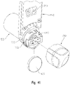
- an electro-mechanical lock core 100 includes a core assembly 102 and an operator actuation assembly 104.
- operator actuation assembly 104 may be actuated to rotate a core plug assembly 106 (see FIG. 2 ) of core assembly 102 about its longitudinal axis 108 and in certain configurations operator actuation assembly 104 may be actuated to move a core keeper 110 of core assembly 102 relative to a core body 112 of core assembly 102.
- Core plug assembly 106 includes a lock interface in the form of a plurality of recesses 114, illustratively two, which receive lock pins 120 of a lock cylinder 122 when core assembly 102 is received in recess 124 of lock cylinder 122, as shown in FIG. 3 .
- Lock pins 120 are in turn coupled to a cam member 126 of lock cylinder 122 which is rotatable.
- cam member 126 may be in turn coupled to a lock system, such as a latch bolt of a door lock, a shank of a padlock or other suitable lock systems.
- core keeper 110 When core assembly 102 is received in recess 124 of lock cylinder 122, core keeper 110 is in a first position wherein it is received in a recess of lock cylinder 122 to hold or otherwise prevent the removal of core assembly 102 from lock cylinder 122 without the movement of core keeper 110 to a second position wherein the core keeper 110 is not received in the recess of lock cylinder 122.
- core body 112 defines a figure eight profile (See FIGS. 5 and 6 ) which is received in a corresponding figure eight profile of lock cylinder 122 (See FIGS. 3 and 4 ).
- the figure eight profile is known as a small format interchangeable core ("SFIC").
- the lock core body 112 includes an upper lock core body having a first cylindrical portion with a first maximum lateral extent, a lower lock core body having a second cylindrical portion with a second maximum lateral extent, and a waist having a third maximum lateral extent, the third maximum lateral extent being less than the first maximum lateral extent and being less than the second maximum lateral extent.
- Core body 112 may also be sized and shaped to be compatible with large format interchangeable cores ("LFIC”) and other known cores.
- Core body 112 may be translated relative to lock cylinder 122 along longitudinal axis 108 to remove core body 112 from lock cylinder 122 when core keeper 110 is received within the envelope of core body 112 such that core body 112 has a figure eight profile and may not be translated relative to lock cylinder 122 along longitudinal axis 108 to remove core body 112 from lock cylinder 122 when core keeper 110 is positioned at least partially outside of the envelope of core body 112.
- electro-mechanical lock core 100 is illustrated in use with lock cylinder 122, electro-mechanical lock core 100 may be used with a plurality of lock systems to provide a locking device which restricts the operation of the coupled lock system.
- Exemplary lock systems include door handles, padlocks, and other suitable lock systems.
- operator actuation assembly 104 is illustrated as including a generally cylindrical knob, other user actuatable input devices may be used including handles, levers, and other suitable devices for interaction with an operator.
- core body 112 of core assembly 102 includes an upper cavity 140 and a lower cavity 142.
- Lower cavity 142 includes a lock actuator assembly 144 (See FIGS. 7 and 8 ) and upper cavity 140 receives a control assembly 146 (See FIGS. 7 and 8 ).
- control assembly 146 restricts various movements of lock actuator assembly 144 to restrict the unauthorized actuation of cam member 126 and/or to restrict movement of core keeper 110.
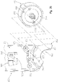
- Lock actuator assembly 144 includes core plug assembly 106, a biasing member 150, and a clutch 152. As illustrated in FIG. 28 , biasing member 150 biases clutch 152 in a spaced apart relationship relative to core plug assembly 106 and may be compressed, as illustrated in FIG. 29 to permit engagement features 154 of core plug assembly 106 to interact with engagement features 156 of clutch 152. In one example, biasing member 150 is a wave spring.
- engagement features 154 and engagement features 156 are a plurality of interlocking protrusions and recesses carries by each of core plug assembly 106 and clutch 152, respectively.
- engagement features 154 may be one or more protrusions received by one or more recess of engagement features 156 or vice versa.
- engagement features 154 and engagement features 156 may be generally planer frictional surfaces which when held in contact couple clutch 152 and core plug assembly 106 to rotate together.
- clutch 152 may have multiple rotational positions relative to core plug assembly 106 about longitudinal axis 108 wherein engagement features 156 of clutch 152 may engage engagement features 154 of core plug assembly 106.
- core assembly 1102 is similar in form and function to core assembly 102. Accordingly, parts of core assembly 1102 will have reference characters corresponding to similar parts of core assembly 102.
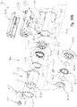
- core assembly 1102 includes a core keeper 1110 and a core body 1112, as illustrated in FIG. 49 .
- core body 1112 of core assembly 1102 includes an upper cavity 1140 and a lower cavity 1142 configured to receive a lock actuator assembly 1144.
- Lock actuator assembly 1144 includes core plug assembly 1106, a retaining member 1155, a biasing member 1150, and a clutch 1152.
- biasing member 1150 biases clutch 1152 in a spaced apart relationship relative to core plug assembly 1106 and may be compressed to permit engagement features 1154 of core plug assembly 1106 to interact with engagement features 1156 of clutch 1152.
- biasing member 1150 is a wave spring.
- Retaining member 1155 illustratively a snap ring or circlip, axially retains core plug assembly 1106 within lower cavity 1142 of core body 1112 while permitting core plug assembly 1106 to rotate about longitudinal axis 1108.
- Retaining member 1155 includes an outwardly extending protrusion 1157 and core body 112 includes a recess 1159 configured to receive protrusion 1157.
- retaining member 1155 is secured around engagement members 1154 of core plug assembly 1106 and protrusion 1157 is received in recess 1159. In this way, retaining member 1155 restrict axial movement of core plug assembly 1106 along longitudinal axis 1108 in either direction 1702 or direction 1704.
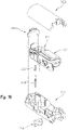
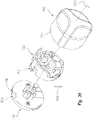
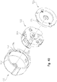
- core plug assembly 106 of lock actuator assembly 144 includes a core plug body 160, a core plug cover 162, a control sleeve 164, and a control keeper coupling assembly 166.
- Control sleeve 164 includes an interior 170 which receives core plug body 160.
- Core plug body 160 includes a flange 172 (see FIG.12 ) that limits the ingress of core plug body 160 into interior 170 of control sleeve 164 along longitudinal axis 108.
- Control sleeve 164 further supports core keeper 110.
- core keeper 110 is integrally formed as part of control sleeve 164.
- core keeper 110 may be a separate component which is coupled to control sleeve 164.
- Core keeper 110 is illustratively shown as being co-extensive with a front face 174 of control sleeve 164 (see FIG. 11 ), but may be spaced apart from front face 174 of control sleeve 164 along longitudinal axis 108.
- a stem portion 176 of core plug cover 162 is also received within interior 170 of control sleeve 164 along longitudinal axis 108. Stem portion 176 is further received within a recess 178 of core plug body 160.
- Core plug cover 162 includes locators 180 which cooperate with locators 182 of core plug body 160 to orient core plug cover 162 relative to core plug body 160 such that openings 184 in core plug cover 162 align with recesses 186 of core plug body 160. Openings 184 and 186 receive lock pins 120 of lock cylinder 122 (see FIG. 1 ).
- the illustrated locators 180 and locators 182 are recesses in core plug cover 162 and protrusions on core plug body 160, respectively. In one embodiment, other arrangements and constructs of locators or fasteners may be used.
- Control keeper coupling assembly 166 is coupled to core plug body 160.
- Control keeper coupling assembly 166 includes a bell crank 190, an axle 192, a biasing member 194, and a cover 196.
- Axle 192 is received in an opening 198 of bell crank 190.
- Axle 192 is further received in a recess 200 of core plug body 160.
- Axle 192 supports bell crank 190 which extends into a second recess 202 of core plug body 160.
- axle 192 is integrally formed with bell crank 190.
- Biasing member 194 is compressed between stem 176 of core plug cover 162 and bell crank 190 of control keeper coupling assembly 166. Referring to FIG. 13 , a first end 204 of biasing member 194 is received over a protrusion 206 of a first leg 208 of bell crank 190. A second end 210 of biasing member 194 is received over a protrusion 212 of stem 176 of core plug cover 162. A flange 214 of stem 176 (see FIG. 11 ) of core plug cover 162 provides a stop surface for second end 210 of biasing member 194.
- Cover 196 of control keeper coupling assembly 166 is received in a recess 220 of core plug body 160.
- Recess 200 and recess 202 intersect with and extend into core plug body 160 from recess 220.
- An exterior surface 222 of cover 196 has a surface profile, in the illustrated embodiment, which matches a surface profile of an exterior surface 224 of core plug body 160.
- Cover 196 and core plug body 160 cooperate to form a cylindrical body.
- Cover 196 includes locators 226 which cooperate with locators 228 of core plug body 160 to orient cover 196 relative to core plug body 160 such that an opening 230 in cover 196 align with recess 202 of core plug body 160.
- a second leg 240 of bell crank 190 may extend through opening 230 of cover 196 and extend above exterior surface 222 of cover 196. Opening 230 of cover 196 and recess 202 of core plug body 160 are sized to also permit second leg 240 of bell crank 190 to be positioned within the cylindrical body formed by core plug body 160 and cover 196 (see FIGS. 9, 10 , and 13 ).
- cover 196 When cover 196 is coupled to core plug body 160 to hold bell crank 190 within core plug body 160 and cover 196, the cylindrical body formed by core plug body 160 and cover 196 is received within interior 170 of control sleeve 164 and oriented such that an opening 238 of control sleeve 164 is aligned with opening 230 of cover 196.
- second leg 240 of bell crank 190 may extend through opening 238 of control sleeve 164 and above an exterior surface 244 of control sleeve 164.
- second leg 240 of bell crank 190 By extending second leg 240 of bell crank 190 into opening 238 of control sleeve 164, second leg 240 of bell crank 190 rotationally couples control sleeve 164 to core plug body 160 such that a rotation of core plug body 160 about longitudinal axis 108 results in a rotation of control sleeve 164 about longitudinal axis 108 in the same direction as core plug body 160.
- control sleeve 164 By retracting second leg 240 of bell crank 190 from opening 238 of control sleeve 164 to a position below exterior surface 222 of cover 196, control sleeve 164 is not rotationally coupled to core plug body 160 and a rotation of core plug body 160 about longitudinal axis 108 does not result in a rotation of control sleeve 164 about longitudinal axis 108.
- FIG. 13 illustrates bell crank 190 with second leg 240 retracted within recess 202 of core plug body 160.
- Biasing member 194 biases bell crank 190 to the position shown in FIG. 13 .
- Core plug body 160 includes a channel 246 which intersects with a front face 248 of core plug body 160 and with recess 202 of core plug body 160.
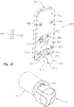
- channel 240 permits an actuator, control pin 700 (see FIG. 32 ), to be inserted into core plug body 160 to move bell crank 190 to a position wherein second leg 240 of bell crank 190 extends into opening 238 of control sleeve 164 to couple control sleeve 164 to core plug body 160.
- FIG. 32 illustrates bell crank 190 with second leg 240 retracted within recess 202 of core plug body 160.
- Biasing member 194 biases bell crank 190 to the position shown in FIG. 13 .
- Core plug body 160 includes a channel 246 which intersects with a front face 248
- clutch 152 includes a channel 250 which extends from a front face 254 of clutch 152 to a rear face 252 of clutch 152.
- Channel 250 of clutch 152 is aligned with channel 246 of core plug body 160.
- an actuator, control pin 700 (see FIG. 32 ), received in channel 250 may extend beyond rear face 252 of clutch 152 and enter channel 246 of core plug body 160.
- a control keeper coupling assembly 1166 is coupled to core plug body 1160.
- Control keeper coupling assembly 1166 includes bell crank 1190, a biasing member 1194, and a cover 1196.
- Bell crank 1190 illustratively includes a first leg 1208 and a second leg 1240 coupled at an axle 1193.
- Axle 1193 is received in a recess 1200 of core plug body 1160 and rotationally supports bell crank 1190 which extends into a second recess 1202 of core plug body 1160.
- first leg 1208, second leg 1240, and axle 1193 are integrally formed.
- first leg 1208, second leg 1240, and axle 1193 could comprise one or more independent components supported by core plug body 1160.
- axle 1193 comprises one or more components supported for rotation within a recess of bell crank 1190.
- First leg 1208 of bell crank 1190 extends in a first direction while second leg 1240 of bell crank 1190 extends in a second direction angularly offset from the first direction.
- the second direction is generally orthogonal relative to the first direction.
- the second direction is generally acute relative to the first direction.
- the second direction is generally relative obtuse to first direction.
- Second leg 1240 couples to axle 1193 at a first end 1241 of second leg 1240. Opposite first end 1241 is a second end 1243 of second leg 1240. Second end 1243 includes an upper portion 1247 and a lower portion 1245.
- FIG. 51 the second direction is generally orthogonal relative to the first direction.
- the second direction is generally acute relative to the first direction.
- the second direction is generally relative obtuse to first direction.
- Second leg 1240 couples to axle 1193 at a first end 1241 of second leg 1240.
- Opposite first end 1241 is a second end 1243 of second leg 1240.
- upper portion 1247 extends generally upwardly and lower portion 1245 extends generally downwardly such that a longitudinal profile of second leg 1240 of bell crank 1190 is generally T-shaped.
- Second leg 1240 cantilevers from axle 1193 such that second end 1243 may deflect relative to first end 1241 and axle 1193 if a sufficient force is applied to upper portion 1147, lower portion 1145, or a point proximate second end 1243.
- Biasing member 1194 is compressed between a stem 1176 of core plug cover 1162 and bell crank 1190 of control keeper coupling assembly 1166. Referring to FIGS. 51 and 52 , a first end 1204 of biasing member 1194 is received over a protrusion 1206 of first leg 1208 of bell crank 1190. A second end 1210 of biasing member 1194 is received over a protrusion 1212 of stem 1176 of core plug cover 1162. A flange 1214 of stem 1176 of core plug cover 1162 provides a stop surface for second end 1210 of biasing member 1194.
- second leg 1240 of bell crank 1190 may extend through an opening 1230 of cover 1196 and upper portion 1247 of second leg 1240 may extend above an exterior surface 1222 of cover 1196. Opening 1230 of cover 1196 and recess 1202 of core plug body 1160 are sized to also permit second leg 1240 of bell crank 1190 to be positioned within the cylindrical body formed by core plug body 1160 and cover 1196 (see FIGS. 51 and 52 ).
- cover 1196 When cover 1196 is coupled to core plug body 1160 to hold bell crank 1190 within core plug body 1160 and cover 1196, the cylindrical body formed by core plug body 1160 and cover 1196 is received within an interior 1170 of control sleeve 1164 and oriented such that an opening 1238 of control sleeve 1164 is aligned with opening 1230 of cover 1196.
- upper portion 1247 of second leg 1240 of bell crank 1190 may extend through opening 1238 of control sleeve 1164 and above an exterior surface 1244 of control sleeve 1164.
- upper portion 1247 of second leg 1240 of bell crank 1190 rotationally couples control sleeve 1164 to core plug body 1160 such that a rotation of core plug body 1160 about longitudinal axis 1108 results in a rotation of control sleeve 1164 about longitudinal axis 1108 in the same direction as core plug body 1160.
- control sleeve 1164 By retracting upper portion 1247 of second leg 1240 from opening 1238 of control sleeve 1164 to a position below exterior surface 1222 of cover 1196, control sleeve 1164 is not rotationally coupled to core plug body 1160 and a rotation of core plug body 1160 about longitudinal axis 1108 does not result in a rotation of control sleeve 1164 about longitudinal axis 1108.
- FIGS. 50A and 52 illustrate bell crank 1190 with upper portion 1247 of second leg 1240 retracted within recess 1202 of core plug body 1160.
- Biasing member 1194 biases bell crank 1190 to the position shown in FIGS. 50A and 52 .
- Core plug body 1160 includes a channel 1246 which intersects with a front face 1248 of core plug body 1160 and with recess 1202 of core plug body 1160.
- Channel 1246 permits an actuator, control pin 1700 (see FIG. 52 ), to be inserted into core plug body 1160 in direction 1702 to move bell crank 1190 to a position wherein upper portion 1247 of second leg 1240 extends into opening 1238 of control sleeve 1164 to couple control sleeve 1164 to core plug body 1160.
- clutch 1152 includes a channel 1250 which extends from a front face 1254 of clutch 1152 to a rear face 1252 of clutch 1152.
- Channel 1250 of clutch 1152 is aligned with channel 1246 of core plug body 1160.
- an actuator, control pin 1700 (see FIG. 52 ), received in channel 1250 in direction 1702 may extend beyond rear face 1252 of clutch 1152 and enter channel 1246 of core plug body 160.
- core plug body 1160 may be rotationally offset relative to control sleeve 1164 about longitudinal axis 1108 such that opening 1238 of control sleeve 1164 is not aligned with opening 1230 of cover 1196. Accordingly, upper portion 1247 of second end 1243 of second leg 1240 of bell crank 1190 may not extend into opening 1238 of control sleeve 1164 when an actuator, control pin 1700 (see Fig. 52 ), is inserted into channel 1246 of core plug body 1160 in direction 1702 to move bell crank 1190. Instead, upper portion 1247 of second leg 1240 may impinge on an inner surface of control sleeve 1164 and second end 1243 may flex relative to first end 1241 of second leg 1240 and axle 1193.
- control sleeve 1164 is rotationally coupled to core plug body 1160.
- lock actuator assembly 144 which includes biasing member 150, clutch 152, core plug body 160 and control sleeve 164 are received in lower cavity 142 of core body 112 through a rear face 260 of core body 112.
- Core body 112 includes a recess 262 to receive core keeper 110 of control sleeve 164 (see FIG. 1 ).
- core body 112 includes a stop 264 which limits the axial movement of clutch 152 towards the front of core body 112 (see FIG. 26 ).
- Control assembly 146 is received in upper cavity 140 of core body 112.
- the components of control assembly 146 are described in more detail herein in relation to FIGS. 14-21 .
- One of the components of control assembly 146, a light guide 266, is positioned forward of an upper wall 268 of core body 112 in a recess 270 of upper wall 268 (see FIG. 7 ).
- Light guide 266 is supported by a cradle 272 of control assembly 146.
- a front wall 274 of cradle 272 is positioned against a front wall 276 of core body 112.
- Control assembly 146 is held in place relative to core body 112 with a top cover 280 and a rear cover 282.
- Top cover 280 includes a plurality of tabs 284 which are positioned under upper wall 268 of core body 112 to hold a front portion of top cover 280 relative to core body 112.
- Rear cover 282 includes a plurality of locators 286, illustratively protrusions, and locators 288, illustratively protrusions.
- Outer locators 286 are received in external recesses 290 of top cover 280, respectively, while inner locators 286 are received in voids 292; thereby each pair of outer and inner locators 286 captures a wall 294 of top cover 280.
- Locators 288 are received in respective recesses 296 of core body 112. Thus, locators 286 are coupled to top cover 280 and locators 288 are coupled to core body 112 to hold the rear end of top cover 280 relative to core body 112. Rear cover 282 is held relative to core body 112 with a fastener 302. Fastener 302 is received in an opening 300 in rear cover 282 and is secured to core body 112 through a threaded aperture 304.
- rear cover 282 In addition to holding control assembly 146 relative to core body 112, rear cover 282 also holds lock actuator assembly 144 relative to core body 112.
- Rear cover 282 includes an opening 310 sized to receive a head 312 of core plug cover 162.
- a stop 314 is provided on core plug cover 162. Stop 314 is positioned to rest against surface 316 of rear cover 282 to prevent the rearward axial movement of core plug cover 162.
- head 312 of core plug cover 162 extends outward from rear cover 282.
- head 312 with openings 184 are illustrated for interfacing with lock pins 120 of lock cylinder 122, different configurations of head 312 are contemplated including recesses and/or protrusions to couple tailpieces or other cam members to lock actuator assembly 144.
- Electro-mechanical lock core 100 may be configured for use with other types of lock cylinder 122, padlocks, rim cylinders, key in knob/lever cylinders, and other locking devices.
- Control assembly 146 includes cradle 272, an electrical assembly 350, a motor 352 controlled by the electrical assembly 350, light guide 266, a blocker 354, and top cover 280.
- Cradle 272 includes various features, walls, recesses, and other geometries to position and hold electrical assembly 350, motor 352, light guide 266, and blocker 354 (see FIG. 8 for an assembled view).
- Cradle 272 on an upper side includes a holder 360 to hold motor 352 and an elongated channel 362 and cradle 364 to hold portions of electrical assembly 350.
- Holder 360 includes a central aperture 366 through which an output shaft 452 of motor 352 extends (see FIG. 27 ).
- motor 352 is a stepper motor.
- cradle 272 on a bottom side includes a recess 370 into which blocker 354 may be positioned.
- Recess 370 intersects with central aperture 366.
- Cradle 272, on a bottom side further includes a recess 372 to accommodate core keeper 110 when core keeper 110 is positioned within core body 112, as explained in more detail herein.
- Electrical assembly 350 includes an electronic controller 380, a wireless communication system 382, one or more input devices 384, one or more output devices 386, and a memory 388 all electrically interconnected through circuitry 390.
- electronic controller 380 is microprocessor-based and memory 388 is a non-transitory computer readable medium which includes processing instructions stored therein that are executable by the microprocessor of electronic controller 380 to control operation of electro-mechanical lock core 100 including positioning blocker 354 in one of a blocking position (see FIG. 20 ) and a release position (see FIG. 21 ).
- non-transitory computer-readable mediums include random access memory (RAM), read-only memory (ROM), erasable programmable read-only memory (e.g., EPROM, EEPROM, or Flash memory), or any other tangible medium capable of storing information.
- RAM random access memory
- ROM read-only memory
- EEPROM erasable programmable read-only memory
- Flash memory any other tangible medium capable of storing information.
- Circuitry 390 includes circuitry on one or more circuit boards 392 (see FIG. 14 ) and a power bus 394 (see FIG. 14 ).
- power bus 394 is operatively coupled to a first electrical contact, illustratively as pogo pin 398 received in a holder 400.
- Pogo pin 398 is operatively coupled to a contact 422 of a power assembly 420 (see FIG. 23 and 27 ) to receive electrical power from a power source 402 (see FIG. 45 ).
- electrical contact 422 is made of brass.
- Power bus 394 is further electrically coupled to additional components of electrical assembly 350 to provide power to electrical assembly 350. Electrical assembly 350 is grounded through core body 112.
- power source 402 is positioned within operator actuation assembly 104 of electro-mechanical lock core 100. In other embodiments, power source 402 may be positioned in core assembly 102 of electro-mechanical lock core 100. Advantages, among others, for incorporating power source 402 in operator actuation assembly 104 is the ease of replacement of power source 402 and the ability to incorporate a battery as the power source with an increased capacity compared to the space constraints of core assembly 102 of electro-mechanical lock core 100. Referring to FIG. 24 , power source 402 is illustrated as a battery 404 incorporated as part of operator actuation assembly 104. Additional details regarding operator actuation assembly 104 are provided herein.
- wireless communication system 382 includes a transceiver and other circuitry needed to receive and send communication signals to other wireless devices, such as an operator device 500.
- wireless communication system 382 includes a radio frequency antenna and communicates with other wireless devices over a wireless radio frequency network, such as a BLUETOOTH network or a WIFI network.
- electro-mechanical lock core 100 communicates with operator device 500 without the need to communicate with other electro-mechanical lock core 100.
- electro-mechanical lock core 100 does not need to maintain an existing connection with other electro-mechanical locking cores 100 to operate.
- One advantage, among others, is that electro-mechanical lock core 100 does not need to maintain network communications with other electro-mechanical lock core 100 thereby increasing the battery life of battery 404.
- electro-mechanical lock core 100 does maintain communication with other electro-mechanical locking cores 100 and is part of a network of electro-mechanical locking cores 100. Exemplary networks include a local area network and a mesh network.
- Exemplary input devices 384 include buttons, switches, levers, a touch display, keys, and other operator actuatable devices which may be actuated by an operator to provide an input to electronic controller 380. Once communication has been established with operator device 500, various input devices 506 of operator device 500 may be actuated by an operator to provide an input to electronic controller 380.
- electro-mechanical lock core 100 requires an actuation of an input device 384 of electro-mechanical lock core 100 prior to taking action based on communications from operator device 500.
- An advantage, among others, for requiring an actuation of an input device 384 of electro-mechanical lock core 100 prior to taking action based on communications from operator device 500 is that electro-mechanical lock core 100 does not need to evaluate every wireless device that comes into proximity with electro-mechanical lock core 100.
- electro-mechanical lock core 100 may use the actuation of input devices 384 to start listening to communications from operator device 500.
- operator actuation assembly 104 functions as an input device 384.
- Operator actuation assembly 104 capacitively senses an operator tap on operator actuation assembly 104 or in close proximity to operator actuation assembly 104.
- Exemplary output devices 386 include visual output devices, audio output device, and/or tactile output devices.
- Exemplary visual output devices include lights, segmented displays, touch displays, and other suitable devices for providing a visual cue or message to an operator of operator device 500.
- Exemplary audio output devices include speakers, buzzers, bells and other suitable devices for providing an audio cue or message to an operator of operator device 500.
- Exemplary tactile output devices include vibration devices and other suitable devices for providing a tactile cue to an operator of operator device 500.
- electro-mechanical lock core 100 sends one or more output signals from wireless communication system 382 to operator device 500 for display on operator device 500.
- Operator device 500 is carried by an operator,
- Exemplary operator device 500 include cellular phones, tablets, personal computing devices, watches, badges, and other suitable devices associated with an operator that are capable of communicating with electro-mechanical lock core 100 over a wireless network.
- Exemplary cellular phones include the IPHONE brand cellular phone sold by Apple Inc., located at 1 Infinite Loop, Cupertino, CA 95014 and the GALAXY brand cellular phone sold by Samsung Electronics Co., Ltd.
- Operator device 500 includes an electronic controller 502, a wireless communication system 504, one or more input devices 506, one or more output devices 508, a memory 510, and a power source 512 all electrically interconnected through circuitry 514.
- electronic controller 502 is microprocessor-based and memory 510 is a non-transitory computer readable medium which includes processing instructions stored therein that are executable by the microprocessor of operator device 500 to control operation of operator device 500 including communicating with electro-mechanical lock core 100.
- Exemplary non-transitory computer-readable mediums include random access memory (RAM), read-only memory (ROM), erasable programmable read-only memory (e.g., EPROM, EEPROM, or Flash memory), or any other tangible medium capable of storing information.
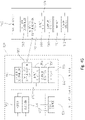
- electronic controller 380 executes an access granted logic 430 which controls the position of blocker 354 in either a blocking position (see FIG. 20 ) and a release position (see FIG. 21 ).
- logic includes software and/or firmware executing on one or more programmable processors, application-specific integrated circuits, field-programmable gate arrays, digital signal processors, hardwired logic, or combinations thereof. Therefore, in accordance with the embodiments, various logic may be implemented in any appropriate fashion and would remain in accordance with the embodiments herein disclosed.
- a non-transitory machine-readable medium 388 comprising logic can additionally be considered to be embodied within any tangible form of a computer-readable carrier, such as solid-state memory, magnetic disk, and optical disk containing an appropriate set of computer instructions and data structures that would cause a processor to carry out the techniques described herein.
- This disclosure contemplates other embodiments in which electronic controller 380 is not microprocessor-based, but rather is configured to control operation of blocker 354 and/or other components of electro-mechanical lock core 100 based on one or more sets of hardwired instructions. Further, electronic controller 380 may be contained within a single device or be a plurality of devices networked together or otherwise electrically connected to provide the functionality described herein.
- Electronic controller 380 receives an operator interface authentication request, as represented by block 432.
- operator interface authentication request 432 is a message received over the wireless network from operator device 500.
- operator interface authentication request 432 is an actuation of one or more of input devices 384.
- operator actuation assembly 104 functions as an input device 384.
- Operator actuation assembly 104 capacitively senses an operator tap on operator actuation assembly 104 or in close proximity to operator actuation assembly 104.
- Electronic controller 380 further receives authentication criteria 434 which relate to the identity and/or access level of the operator of operator device 500.
- the authentication criteria is received from operator device 500 or communicated between electronic controller 380 and operator device 500.
- Access granted logic 430 based on operator interface authentication request 432 and authentication criteria 434 determines whether the operator of operator device 500 is granted access to actuate core plug assembly 106 which in turn actuates cam member 126 in the illustrated embodiment or is denied access to actuate core plug assembly 106. If the operator of operator device 500 is granted access to actuate core plug assembly 106, access granted logic 430 powers motor 352 to move blocker 354 to the release position, as represented by block 436. If the operator of operator device 500 is denied access to actuate core plug assembly 106, access granted logic 430 maintains blocker 354 in the blocking position, as represented by block 438.
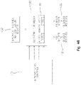
- a first exemplary embodiment 530 of electrical assembly 350 is illustrated in FIG. 47 .
- FIG. 48 A second exemplary embodiment 570 of electrical assembly 350 is illustrated in FIG. 48 .
- Light guide 266 communicates the output of diodes (see FIGS. 47 and 48 ), an exemplary output device, to an operator external to electro-mechanical lock core 100.
- light guide 266 is positioned at the front of cradle 272.
- Cradle 272 includes a recess 450 in front wall 274 which receives a central portion of light guide 266. As shown in FIG. 1 , the central portion of light guide 266 is visible above operator actuation assembly 104 when electro-mechanical lock core 100 is assembled.
- motor 352 includes a threaded output shaft 452 which is rotational about axis 454 and is received in a threaded aperture 456 of blocker 354.
- the orientation of blocker 354 is maintained by the shape and size of recess 370 in cradle 272. As such, due to a rotation of threaded output shaft 452 in a first direction 458, blocker 354 is moved downwardly in direction 462 and due to a rotation of threaded output shaft 452 in a second direction 460, blocker 354 is moved upwardly in direction 464.
- Blocker 354 cooperates with clutch 152 to deny or grant access to core plug assembly 106.
- clutch 152 includes a circumferential groove 466 having a cylindrical lower surface 468.
- Blocker 354 includes a cylindrical lower profile 470 which generally matches cylindrical lower surface 468 of clutch 152.
- clutch 152 is restricted in axial movement along longitudinal axis 108 relative to blocker 354.
- the relationship shown in FIG. 20 is referred to as a blocked position of blocker 354 due to the restricted axial movement of clutch 152 relative to blocker 354 along longitudinal axis 108.
- clutch 152 may move to a greater degree axially along longitudinal axis 108 relative to blocker 354.
- the relationship shown in FIG. 21 is referred to as a release position of blocker 354 due to the less restricted axial movement of clutch 152 relative to blocker 354 along longitudinal axis 108.
- a protrusion of clutch 152 is received in a groove of blocker 354 or is otherwise blocked in axial movement towards core plug assembly 106 when blocker 354 is in the blocked position.
- clutch 152 is able to freely rotate about longitudinal axis 108 while blocker 354 is in the blocked position ( FIG. 20 ) and while blocker 354 is in the released position ( FIG. 21 ).
- the interaction of blocker 354 and clutch 152 is explained in more detail herein.
- electro-mechanical lock core 100 includes a position sensor 600 supported by circuit board 392.
- Position sensor 600 determines a position of blocker 354 to provide a feedback to electronic controller 380 when blocker 354 is in the blocked position.
- Position sensor 600 includes a first leg 602 having a first aperture 604 (see FIG. 20 ) and a second leg 606 having a second aperture 608 (see FIG. 18 ).
- One of first leg 602 and second leg 606 includes a light source 610 (see FIG. 18A ), such as a light emitting diode, and the other of first leg 602 and second leg 606 includes a detector 612 which detects the light emitted by light source 610.
- light source 610 is powered to emit light when motor 352 is operating.
- a vertical channel 616 is formed between first leg 602 and second leg 606.
- the vertical channel 616 is sized to receive blocker 354.
- blocker 354 When blocker 354 is in the release position (see FIG. 21 ), blocker 354 is positioned in channel 616 at a height blocking the light from light source 610 reaching detector 612 and a voltage on a position sense line 618 monitored by electronic controller 380 is high.
- blocker 354 When blocker 354 is in the blocking position (see FIG. 20 ), blocker 354 is in channel 616 at a height permitting the light from light source 610 to reach detector 612, thereby activating a switch of detector 612 so that the voltage on the position sense line 618 monitored by electronic controller 380 is low.
- Blocker 354' includes a window 620. With blocker 354' and position sensor 600 positioned lower, the light from light source 610 is detected by detector 612 when blocker 354' is in the release position and the light from light source 610 is blocked from detector 612 when blocker 354' is in the blocked position. Although a line-of-sight optical position sensor 600 is shown, other position sensors may be used to sense a position of blocker 354 relative to clutch 152. Exemplary alternative position sensors include hall effect sensors, current monitoring sensors, switched activated sensors, and other suitable sensing devices for sensing a position of a mechanical device.
- Power assembly 420 is illustrated. Power assembly 420 is received in lower cavity 142 of core body 112 as illustrated in FIG. 26 .
- Power assembly 420 includes a first insulator housing 424 and a second insulator housing 426 which capture contact 422 and a conductor 428.
- conductor 428 is a beryllium copper canted coil spring or other suitable conductive devices.
- Conductor 428 is in electrical contact with operator actuation assembly 104 to receive power from battery 404 while permitting a free rotation of operator actuation assembly 104 about axis 108.
- Contact 422 is in electrical contact with conductor 428 to receive electrical power from conductor 428 and pass the electrical power on to pogo pin 398.
- Power assembly 420 includes a central opening 628 to receive operator actuation assembly 104.
- Power assembly 420 is held in place in core body 112 by a stop 264 of core body 112 and a cover 630 threaded into a front portion 632 of core body 112.
- Cover 630 includes a recess 634 which carries a conductor 636.
- Cover 630 is electrically coupled to core body 112 through the threaded engagement and conductor 636 is electrically coupled to cover 630.
- core body 112 is grounded and conductor 636 is in electrical contact with operator actuation assembly 104 to ground operator actuation assembly 104.
- conductor 636 is a beryllium canted coil spring.
- Cover 630 includes a central opening 640 to receive operator actuation assembly 104.
- Operator actuation assembly 104 is illustrated. All of the components of operator actuation assembly 104 rotate about longitudinal axis 108 as a unit.
- Operator actuation assembly 104 includes a power transfer ring 654 captured between a first insulator ring 650 and a second insulator ring 652.
- conductor ring 654 is in electrical contact with conductor 428 of power assembly 420 to transfer power to conductor 428 throughout a movement of operator actuation assembly 104 along axis 108 in direction 702 and direction 704.
- conductor ring 654 is a brass power transfer ring.
- Second insulator ring 652 includes a recess to receive a first leg 658 of a power transfer conductor 660.
- a first end 664 of first leg 658 of conductor 660 is in electrical contact with conductor ring 654. As shown in FIG. 27 , first end 664 has a bent profile which biases first leg 658 of power transfer conductor 660 into contact with conductor ring 654.
- first leg 658 of power transfer conductor 660 is covered by an insulator sleeve 662.
- a second end 672 of second leg 670 of power transfer conductor 660 is held in electrical contact with a conductor clip 674 which is in turn in electrical contact with a terminal portion of battery 404.
- First leg 658 of conductor 660 and insulator sleeve 662 also pass through a channel 676 of a knob base shaft 680.
- a stem 682 of knob base shaft 680 has an end portion 684 with a first diameter sized to be received within and generally match the diameter of channel 250 of clutch 152 and a central opening 628 of power assembly 420.
- Stem 682 of knob base shaft 680 has an intermediate portion 686 with a second diameter, larger than the first diameter of end portion 684, sized to be received within and generally match the diameter of central opening 640 of cover 630.
- Knob base shaft 680 further includes a central opening 690 having a front portion 692 and a rear portion 694. Front portion 692 has a larger diameter than rear portion 694. Rear portion 694 of central opening 690 includes a threaded portion 696 which is threadably engaged by a threaded head 698 of a control pin 700. As shown in FIG. 27 , control pin 700 is threaded into knob base shaft 680 from the rear. As explained herein, an operator may engage control pin 700 with a tool (not shown) which is configured to engage tool engagement end 706 of control pin 700. Illustratively, tool engagement end 706 of control pin 700 is a socket configured to receive a hex head tool. The operator may advance control pin 700 in direction 702 (see FIG. 27 ) along longitudinal axis 108 and then subsequently retract control pin 700 in direction 704 along axis 108. As explained in more detail herein, an end 710 of control pin 700 may be used to actuate bell crank 190.
- operator actuation assembly 104 further includes a knob base 720 and a battery support 722.
- Battery support 722 is coupled to knob base 720 with a plurality of fasteners 724 threaded into apertures 726 of knob base 720.
- Knob base 720 includes a central sleeve 730 and a base 732. A central opening 734 passes through both central sleeve 730 and base 732.
- Sleeve 730 includes a first plurality of recesses 736 spaced around central opening 734 and a second plurality of recesses 738 spaced around central opening 734.
- First plurality of recesses 736 receives protrusions 740 (see FIG. 15 ) of battery support 722.
- Second plurality of recesses 738 receives protrusions 742 of knob base shaft 680.
- a longitudinal length of second plurality of recesses 738 along longitudinal axis 108 is greater than a longitudinal length of protrusions 742 of knob base shaft 680.
- knob base 720 and battery support 722 function to capture knob base shaft 680, but permit relative movement between knob base shaft 680 and the assembly of knob base 720 and battery support 722 along axis 108 in direction 702 and direction 704.
- a biasing member 750 is placed between a stop surface 752 in central opening 690 of knob base shaft 680 and a stop surface 754 of battery support 722. Biasing member 750 biases the assembly of knob base 720 and battery support 722 in direction 704 relative to knob base shaft 680 which as explained in more detail herein is fixably coupled to clutch 152.
- knob base shaft 680 is secured to clutch 152 with a fastener, illustratively a set screw 712 which is threaded into a threaded bore 714 in clutch 152.
- Set screw 712 presses against a flat 688 of knob base shaft 680 to prevent a rotation of knob base shaft 680 relative to clutch 152 .
- knob base shaft 680 is threaded into clutch 152 prior to set screw 712 being advanced in bore 714 into engagement with the flat 688 of knob base shaft 680.
- knob base 720 has a recess 760 into which a ring 762 is placed. Ring 762 extends into a recess 764 in knob base shaft 680 to couple knob base shaft 680 to knob base 720 such that under a first level of force in direction 702, knob base shaft 680 and knob base 720 move together. Under a second level of force in direction 702, greater than the first level of force, ring 762 is displaced from recess 764 of knob base shaft 680 and knob base 720 may move in direction 702 relative to knob base shaft 680 as shown in FIG. 30 .
- ring 762 is a steel canted coil spring.
- Spring 750 also absorbs an initial large spike of the external force and assists in returning operator actuation assembly 104 to the position shown in FIG. 26 .
- operator actuation assembly 104 further includes a battery holder board 780 which is received in recess 782 of battery support 722.
- Battery holder board 780 includes the contacts which align with the terminals of battery 404 and a clip 786 which holds battery 404 against battery holder board 780.
- Battery holder board 780 further includes a capacitive sensing circuit 784 and a power interrupt circuit 788.
- Capacitive sensing circuit 784 detects when an operator is in proximity of a knob cover 790 of operator actuation assembly 104 or touches knob cover 790 of operator actuation assembly 104.
- Power interrupt circuit 788 interrupts the power provided by battery 404 to electrical assembly 350 for a short period of time when capacitive sensing circuit 784 detects an operator is in proximity of a knob cover 790 of operator actuation assembly 104 or touches knob cover 790 of operator actuation assembly 104. This interruption of power signals electronic controller 380 that a potential operator is in close proximity to electro-mechanical lock core 100.
- capacitive sensing circuit 784 and power interrupt circuit 788 in operator actuation assembly 104 is that the components of electrical assembly 350 may be in a low power mode until the interruption of power is sensed and thus extend the life of battery 404.
- power interrupt circuit 788 is replaced with a signal transmission unit that in response to a detection by capacitive sensing circuit 784 will send a wake-up signal to electrical assembly 350.
- Knob cover 790 is removably coupled to knob base 720.
- knob cover 790 includes three spaced apart groupings (one grouping shown) of a front rib 792 and a rear rib 794 which define a channel 796.
- the channels 796 receive a rib 798 (two instances shown) of knob base 720 to hold knob cover 790 against axial movement in direction 702 or direction 704 relative to knob base 720.
- an assembly including knob base 720 and knob cover 790 is capable of moving in direction 702 and direction 704.
- Knob cover 790 is held against rotational movement in direction 802 (see FIG. 24 ) relative to knob base 720 due to arm 804 of battery support 722 which is received in one of recesses 806 of knob base 720 and against rotational movement in direction 800 relative to knob base 720 due to a wall of knob base 720.
- knob cover 790 needs to be removed from the remainder of operator actuation assembly 104.
- a knob cover removal tool 850 for removing knob cover 790 is shown.
- Tool 850 includes a back housing 852 and a front housing 854 secured together with fasteners 856.
- a movable coupler 860 is captured between back housing 852 and front housing 854.
- a first operator actuatable portion 868 of movable coupler 860 extends through a window 866 of front housing 854.
- a second operator actuatable portion 870 of movable coupler 860 extends from a lower portion of front housing 854.
- Movable coupler 860 is moveable in direction 888, direction 890, direction 892, and direction 894 relative to front housing 854.
- back housing 852 includes a lower portion having a scalloped profile 862.
- the lower portion of back housing 852 includes a plurality of locators 864 which are spaced to be received in corresponding locators 880 of knob base 720.
- Movable coupler 860 includes a locator 872 which is received in a corresponding locator 882 of knob cover 790.
- tool 850 is coupled to operator actuation assembly 104 through a mating of locators 864 and 880 along a first direction generally parallel with axis 108 and through a mating of locators 872 and 882 along a second direction generally perpendicular to the first direction of locators 864 and 880.
- knob cover 790 is illustrated.
- tool 850 is positioned so that back housing 852 is between knob base 720 and lock cylinder 122 and the assembly knob base 720 and knob cover 790 is rotated in directions 892, 894 to align locators 880 of knob base 720 with locators 864 of tool 850.
- Tool 850 is then moved in direction 704 to position locators 864 of tool 850 in locators 880 of knob base 720.
- Movable coupler 860 is then moved downward in direction 890 to position locator 872 of tool 850 in locator 882 of knob cover 790 as shown in FIG. 37 .
- locator 872 of tool 850 presses against arm 804 of battery support 722.
- Arm 804 of battery support 722 moves in direction 890 within recesses 806 of knob base 720.
- This movement of arm 804 downward permits front rib 792 and rear rib 794 of knob cover 790 to rotate in direction 892 such that rib 798 of knob base 720 is no longer positioned in channel 796 of knob cover 790.
- this movement may be accomplished by moving movable coupler 860 and knob cover 790 in direction 892 relative to front housing 854 and back housing 852 which is held firm or by holding movable coupler 860 and knob cover 790 firm and moving front housing 854 and back housing 852 in direction 894.
- movable coupler 860 may be moved up in direction 888 and knob cover 790 may be removed from knob base 720 in direction 704, as illustrated in FIG. 41 .
- battery 404 may be removed from battery holder board 780.
- control pin 700 may access tool engagement end 706 of control pin 700 to move control pin 700 in one or directions 702 and 704.
- the position of control pin 700 is important to a movement of core keeper 110 from outside of core body 112 (see FIG. 42 ) to inside of core body 112 (see FIG. 44 ).
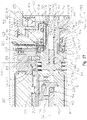
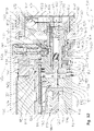
- FIG. 26 illustrates a sectional view of electro-mechanical lock core 100 with blocker 354 in the first blocking position of FIG. 20 wherein a lower portion of blocker 354 is received in circumferential groove 466 of clutch 152.
- FIG. 26 is the rest position of electro-mechanical lock core 100. In the rest position, operator actuation assembly 104 and clutch 152 are freely rotatable about longitudinal axis 108 and blocker 354 prevents the axial movement of clutch 152 in direction 702. Thus, clutch 152 remains spaced apart from core plug body 160 and core plug body 160 cannot be rotated about longitudinal axis 108 to rotate core plug cover 162 and the locking device coupled to core plug cover 162.
- blocker 354 has been moved in direction 464 by motor 352 to the second release position of FIG. 21 wherein a lower portion of blocker 354 is positioned outside of circumferential groove 466. This is an access position for electro-mechanical lock core 100.
- an operator may move operator actuation assembly 104 and clutch 152 in direction 702 to bring engagement features 156 of clutch 152 into engagement with engagement features 154 of core plug body 160, as illustrated in FIG. 29 .
- an operator may rotate operator actuation assembly 104 to effect a rotation of core plug cover 162 and an actuation of the locking device coupled to core plug cover 162.
- control pin 700 remains spaced apart from bell crank 190.
- second leg 240 of bell crank 190 remains below opening 238 of control sleeve 164 (see FIG. 13 ) and control sleeve 164 does not rotate with core plug body 160. Therefore, core keeper 110 remains positioned external to core body 112 as shown in FIG. 42 .
- a biasing member 900 illustratively a torsion spring, is coupled to a protrusion 910 of core body 112 with a first leg 902 that presses against core keeper 110 and a second leg that presses against core body 112.
- Torsion spring 900 biases core keeper 110 to be positioned external to core body 112.
- FIGS. 50A , 50B , and 53-55 An exemplary biasing member 1900 of second exemplary core assembly 1102 is illustrated in FIGS. 50A , 50B , and 53-55 .
- upper cavity 1140 of core body 1112 receives a control assembly 1146. Similar to control assembly 146 of core assembly 102, control assembly 1146 restricts various movements of lock actuator assembly 1144 to restrict unauthorized actuation of a cam member 1126 and/or to restrict movement of core keeper 1110.
- Control assembly 1146 is held in place relative to core body 1112 with a top cover 1280 and a rear cover 1282 and includes a cradle 1272, a light guide 266, and a blocker 1354 (see FIG. 52 ).
- a bottom side of cradle 1272 is defined by a generally arcuate surface.
- cradle 1272 on a bottom side includes biasing member 1900 integrally formed with cradle 1272.
- biasing member 1900 comprises one or more independent components and is supported by cradle 1272.
- a bottom side of cradle 1272 further includes a recess 1372 to accommodate core keeper 1110 when core keeper 1110 is positioned within an envelope of core body 1112.
- biasing member 1900 includes a base 1901 integrally formed with cradle 1272.
- a biasing arm 1903 is integrally formed with base 1901 and extends generally outwardly therefrom. In this way, biasing arm 1903 cantilevers from base 1901.
- biasing arm 1903 mirrors the generally arcuate shape of a bottom side of cradle 1272.
- a distal end of biasing arm 1903 includes a raised portion configured to abut core keeper 1110 when core keeper 1110 is either positioned outside of the envelope of core body 1112 (see FIG. 53 ) or when core keeper 1110 is received at or immediately within the envelope of core body 1112 (see FIGS. 54 and 55 ).
- biasing member 1900 biases core keeper 1110 to be positioned external to core body 1112. Accordingly, core keeper 1110 remains outside the envelope of core body 1112 unless and until a torque in a direction 1894 is applied to control sleeve 1164 sufficient to overcome a biasing torque exerted by biasing member 1900 in direction 1892. When such a sufficient torque is applied to control sleeve 1164 in direction 1894, biasing arm 1903 deflects upwardly relative to base 1901. As torque is continually applied to control sleeve 1164 in direction 1894, core keeper 1110 rotates inwardly past the raised portion of the distal end of biasing arm 1903 and is retracted within the envelope of core body 1112.
- biasing arm 1903 returns to its original shape and core keeper 1110 is now retained within the envelope of core body 1112.
- Core keeper 1110 remains within the envelope of core body 1112 unless and until a torque in direction 1892 is applied to control sleeve 1164 sufficient to upwardly deflect biasing arm 1903 relative to base portion 1901 such that core keeper 1110 is positioned outside of core body 1112.
- control pin 700 has been moved in direction 702 relative to knob base shaft 680.
- the ability to move control pin 700 in direction 702 relative to clutch 152 is limited because the head of control pin 700 bottoms out against the clutch 152.
- An advantage, among others, is that an unauthorized operator is unable to visually inspect the region between clutch 152 and core plug 160 and to prevent the ability to inject an adhesive in the space between clutch 152 and core plug 160.
- FIG. 31 corresponds to FIG. 26 and FIG. 32 corresponds to FIG. 29 .
- electro-mechanical lock core 100 is in a control position wherein control pin 700 actuates bell crank 190 to raise second leg 240 of bell crank 190 into opening 238 of control sleeve 164.
- second leg 240 of bell crank 190 in opening 238 of control sleeve 164 and engagement features 156 of clutch 152 are engaged with engagement features 154 of core plug body 160
- control actuation assembly 104 about longitudinal axis 108
- control sleeve 164 rotates with core plug body 160 and core keeper 110 is retracted to within core body 112.
- electro-mechanical lock core 100 may be removed from lock cylinder 122.
Landscapes
- Engineering & Computer Science (AREA)
- Mechanical Engineering (AREA)
- Physics & Mathematics (AREA)
- Electromagnetism (AREA)
- Quick-Acting Or Multi-Walled Pipe Joints (AREA)
- Details Of Connecting Devices For Male And Female Coupling (AREA)
- Manufacturing Of Electrical Connectors (AREA)
- Lock And Its Accessories (AREA)
Claims (15)
- Noyau de verrou interchangeable (100) pour son utilisation avec un dispositif de verrou ayant un état verrouillé et un état déverrouillé, le noyau de verrou interchangeable (100) pouvant être retiré d'une ouverture du dispositif de verrou, le noyau de verrou interchangeable (100) comprenant :un corps de noyau de verrou (112) ayant une enveloppe de corps de noyau de verrou extérieure ;un barillet mobile (106) positionné dans le corps de noyau de verrou (112), le barillet mobile (106) ayant une première position par rapport au corps de noyau de verrou (112) qui correspond au dispositif de verrou dans l'état verrouillé et une seconde position par rapport au corps de noyau de verrou (112) qui correspond au dispositif de verrou dans l'état déverrouillé ; etune gâche de noyau (110) couplée de façon mobile au corps de noyau de verrou (112), la gâche de noyau (110) pouvant être positionnée dans une position de retenue dans laquelle la gâche de noyau (110) s'étend au-delà de l'enveloppe de corps de noyau de verrou afin de maintenir le corps de noyau de verrou (112) dans l'ouverture du dispositif de verrou et une position de retrait dans laquelle la gâche de noyau (110) est rétractée par rapport à l'enveloppe de corps de noyau de verrou afin de permettre le retrait du corps de noyau de verrou (112) de l'ouverture du dispositif de verrou ;caractérisé par un actionneur (144) mobile par rapport à la gâche de noyau (110), l'actionneur (144) étant supporté par le corps de noyau de verrou (112), mobile par rapport au corps de noyau de verrou (112) dans de multiples degrés de liberté, et couplé opérationnellement à la gâche de noyau (110) indépendamment du barillet mobile (106), l'actionneur (144) ayant une première position correspondant à la position de retrait de la gâche de noyau (110) et une seconde position correspondant à la position de retenue de la gâche de noyau (110), l'actionneur (144) nécessitant un mouvement dans chacun de deux degrés de liberté indépendamment du barillet mobile (106) pour se déplacer de la seconde position à la première position.
- Noyau de verrou interchangeable (100) selon la revendication 1, dans lequel le mouvement dans chacun de deux degrés de liberté comprend une translation et une rotation.
- Noyau de verrou interchangeable (100) selon la revendication 2, moyennant quoi, après la translation, l'actionneur (144) est couplé opérationnellement à la gâche de noyau (110), moyennant quoi, après la translation, la rotation de l'actionneur (144) produit une rotation de la gâche de noyau (110).
- Noyau de verrou interchangeable (100) selon la revendication 1, dans lequel l'actionneur (144) comprend une douille de réception d'outil.
- Noyau de verrou interchangeable (100) selon la revendication 1, dans lequel l'actionneur (144) comprend une goupille de commande (700) reçue par filetage dans le noyau de verrou interchangeable (100).
- Noyau de verrou interchangeable (100) selon l'une quelconque des revendications précédentes, comprenant en outre :
un ensemble d'actionnement d'opérateur (104) opérationnel pour actionner sélectivement le barillet mobile (106), l'ensemble d'actionnement d'opérateur (104) étant supporté de façon mobile par le corps de noyau de verrou (112). - Noyau de verrou interchangeable (100) selon la revendication 6, dans lequel l'ensemble d'actionnement d'opérateur (104) comprend un bouton comportant un couvre-bouton amovible couvrant sélectivement une source d'alimentation située dans le bouton, facultativement la source d'alimentation comprend une batterie.
- Noyau de verrou interchangeable (100) selon la revendication 6, dans lequel l'ensemble d'actionnement d'opérateur (104) comporte une source d'alimentation, facultativement la source d'alimentation comprend une batterie.
- Noyau de verrou interchangeable (100) selon la revendication 7, dans lequel le bouton comprend en outre un accès d'outil à travers lequel un outil (850) peut être positionné pour entrer dans le corps de noyau de verrou (112).
- Noyau de verrou interchangeable (100) selon la revendication 9, dans lequel la source d'alimentation couvre l'accès d'outil lorsque la source d'alimentation est engagée de façon opérationnelle avec l'ensemble d'actionnement d'opérateur (104), moyennant quoi la source d'alimentation peut être retirée de l'ensemble d'actionnement d'opérateur (104) pour permettre à l'outil (850) d'entrer dans le corps du noyau de verrou (112) à travers l'accès d'outil.
- Noyau de verrou interchangeable (100) selon l'une quelconque des revendications précédentes, dans lequel le corps de noyau de verrou (112) comporte un corps de noyau de verrou supérieur ayant une première portion cylindrique avec une première étendue latérale maximale, un corps de noyau de verrou inférieur ayant une seconde portion cylindrique avec une deuxième étendue latérale maximale, et un étranglement ayant une troisième étendue latérale maximale, la troisième étendue latérale maximale étant inférieure à la première étendue latérale maximale et étant inférieure à la deuxième étendue latérale maximale.
- Noyau de verrou interchangeable (100) selon l'une quelconque des revendications précédentes, comprenant en outre :
un manchon de commande (164) portant la gâche de noyau (110), le barillet mobile (106) étant positionné au sein du manchon de commande (164). - Noyau de verrou interchangeable (100) selon l'une quelconque des revendications précédentes, dans lequel, dans la position de retrait, la gâche de noyau (110) est positionnée totalement au sein de l'enveloppe de corps de noyau de verrou.
- Noyau de verrou interchangeable (100) selon l'une quelconque des revendications précédentes, comprenant en outre :
un embrayage (152) pouvant s'engager avec le barillet mobile (106) dans une position d'engagement dans laquelle l'embrayage (152) est capable de conférer une rotation au barillet mobile (106) afin d'actionner le barillet mobile (106) entre la première position et la seconde position. - Noyau de verrou interchangeable (100) selon la revendication 14, comprenant en outre un moteur (352) supporté par le corps de noyau de verrou (112), le moteur (352) pouvant être actionné dans une position de refus de moteur dans laquelle l'embrayage (152) n'est pas autorisé à atteindre la position d'engagement et une position d'autorisation de moteur dans laquelle l'embrayage (152) est autorisé à atteindre la position d'engagement, et facultativement le moteur (352) est positionné à l'extérieur du barillet mobile (106).
Applications Claiming Priority (2)
| Application Number | Priority Date | Filing Date | Title |
|---|---|---|---|
| US201762556195P | 2017-09-08 | 2017-09-08 | |
| PCT/US2018/050117 WO2019051337A1 (fr) | 2017-09-08 | 2018-09-07 | Partie centrale de verrou électromécanique |
Publications (3)
| Publication Number | Publication Date |
|---|---|
| EP3679207A1 EP3679207A1 (fr) | 2020-07-15 |
| EP3679207A4 EP3679207A4 (fr) | 2021-06-23 |
| EP3679207B1 true EP3679207B1 (fr) | 2022-08-03 |
Family
ID=65635196
Family Applications (1)
| Application Number | Title | Priority Date | Filing Date |
|---|---|---|---|
| EP18853917.5A Active EP3679207B1 (fr) | 2017-09-08 | 2018-09-07 | Partie centrale de verrou électromécanique |
Country Status (7)
| Country | Link |
|---|---|
| US (1) | US11913254B2 (fr) |
| EP (1) | EP3679207B1 (fr) |
| CN (1) | CN111094676B (fr) |
| AU (1) | AU2018330295B2 (fr) |
| CA (1) | CA3075189C (fr) |
| ES (1) | ES2927419T3 (fr) |
| WO (1) | WO2019051337A1 (fr) |
Families Citing this family (11)
| Publication number | Priority date | Publication date | Assignee | Title |
|---|---|---|---|---|
| TWI745456B (zh) | 2016-10-19 | 2021-11-11 | 美商貝斯特艾瑟斯解決方案股份有限公司 | 電機式鎖芯裝置、系統及操作電機式鎖芯裝置之方法 |
| WO2019051337A1 (fr) | 2017-09-08 | 2019-03-14 | Dormakaba Usa Inc. | Partie centrale de verrou électromécanique |
| US11466473B2 (en) | 2018-04-13 | 2022-10-11 | Dormakaba Usa Inc | Electro-mechanical lock core |
| CN112752891B (zh) | 2018-04-13 | 2022-08-05 | 多玛卡巴美国公司 | 机电锁芯 |
| US11952801B2 (en) | 2019-04-05 | 2024-04-09 | dormakaba USA, Inc | Electro-mechanical lock core with a cam member tailpiece |
| CA3130681C (fr) * | 2019-04-05 | 2023-12-12 | Dormakaba Usa Inc. | Noyau de verrou electromecanique dote d'une queue de pene d'un element came |
| USD891901S1 (en) | 2019-04-05 | 2020-08-04 | Dormakaba Usa Inc. | Knob |
| CN114391057B (zh) | 2019-09-13 | 2023-09-12 | 多玛卡巴美国公司 | 管状出口装置以及安装方法 |
| US11933074B2 (en) * | 2021-02-04 | 2024-03-19 | The Eastern Company | Electrical cam lock with manual override |
| EP4359624A1 (fr) * | 2021-06-25 | 2024-05-01 | Avantis Hardware Ltd | Appareil de serrure, parties correspondantes et procédé de montage d'un barillet de serrure |
| US12509910B2 (en) | 2022-11-21 | 2025-12-30 | Knox Associates, Inc. | Electronic lock core replacement methods |
Family Cites Families (677)
| Publication number | Priority date | Publication date | Assignee | Title |
|---|---|---|---|---|
| US3298211A (en) * | 1964-12-21 | 1967-01-17 | Russell | Sleeve for key-actuated mechanism |
| US3347072A (en) | 1965-06-28 | 1967-10-17 | Bretan H | Electronic solid state lock mechanism |
| US3824817A (en) | 1973-03-08 | 1974-07-23 | Keystone Consolidated Ind Inc | Removable cylinder lock |
| US3905213A (en) | 1974-04-05 | 1975-09-16 | Locking Systems Inc | Removable core differential mechanism |
| US3990283A (en) | 1975-10-20 | 1976-11-09 | Schlage Lock Company | Removable cylinder for a lock |
| USRE31910E (en) | 1980-08-04 | 1985-06-11 | Medeco Security Locks, Inc. | Removable core cylinder lock |
| US4386510A (en) | 1981-03-02 | 1983-06-07 | Best Lock Corporation | Key-changeable lock core |
| US4484462A (en) | 1982-05-03 | 1984-11-27 | Kason Industries, Inc. | Removable cylinder lock |
| US4526256A (en) | 1982-12-06 | 1985-07-02 | Schlage Lock Company | Clutch mechanism |
| GB2178476A (en) | 1984-10-06 | 1987-02-11 | Lowe & Fletcher Ltd | Lock with controllable clutch |
| CH669425A5 (fr) | 1985-06-12 | 1989-03-15 | Bauer Kaba Ag | |
| US4789859A (en) | 1986-03-21 | 1988-12-06 | Emhart Industries, Inc. | Electronic locking system and key therefor |
| US4747281A (en) | 1986-07-02 | 1988-05-31 | Monahan Brian J | Randomly and integrally re-keyable lock apparatus and method |
| US4876783A (en) | 1987-06-19 | 1989-10-31 | Progressive Security Products, Inc. | Method and apparatus for conversion of doorknob lock sets |
| US4850210A (en) * | 1987-09-21 | 1989-07-25 | Richard S. Adler | Lock adjustable to operate with different keys |
| GB2231367B (en) | 1989-04-13 | 1993-05-19 | Chubb Lips Nederland Bv | Lock with an electromechanical release mechanism |
| US4998422A (en) | 1989-08-30 | 1991-03-12 | Best Lock Corporation | Removable core padlock with bolt retainer |
| US4995249A (en) * | 1989-10-23 | 1991-02-26 | Best Lock Corporation | Door handle assembly with hollow knob and interchangeable lock core |
| US4998423A (en) | 1990-01-05 | 1991-03-12 | Hsu Fong S | Ring shaped hanging lock with replaceable core |
| US5044180A (en) | 1990-05-25 | 1991-09-03 | Master Lock Company | Rekeyable shrouded lock |
| US5010753A (en) | 1990-07-06 | 1991-04-30 | Lori Corporation | Interchangeable core lock |
| US5507162A (en) | 1990-10-11 | 1996-04-16 | Intellikey Corp. | Eurocylinder-type assembly for electronic lock and key system |
| US5235832A (en) | 1991-01-23 | 1993-08-17 | The Eastern Company | Locks and switch locks having substitutable plug-type operator assemblies |
| US5121618A (en) | 1991-07-25 | 1992-06-16 | Rita Scott | Attachment for transforming lock cylinders into interchangeable cores |
| US5933086A (en) | 1991-09-19 | 1999-08-03 | Schlage Lock Company | Remotely-operated self-contained electronic lock security system assembly |
| ES1019766Y (es) | 1991-12-27 | 1993-01-01 | Talleres De Escoriaza, S.A. (Tesa) | Dispositivo de embrague para cerraduras electricas. |
| AU673983B2 (en) | 1992-01-09 | 1996-12-05 | Ge Security, Inc. | Secure entry system with radio communication |
| US5552777A (en) | 1992-02-14 | 1996-09-03 | Security People, Inc. | Mechanical/electronic lock and key |
| US6552650B1 (en) | 1992-02-14 | 2003-04-22 | Asil T. Gokcebay | Coin collection lock and key |
| US5367295A (en) | 1992-02-14 | 1994-11-22 | Security People, Inc. | Conventional mechanical lock cylinders and keys with electronic access control feature |
| IT1258149B (it) | 1992-09-15 | 1996-02-20 | Italiana Serrature Affini | Serratura ad abilitazione elettrica |
| US5209087A (en) | 1992-09-16 | 1993-05-11 | Cox Terry L | High security removable core cylinder lock |
| US5749253A (en) | 1994-03-30 | 1998-05-12 | Dallas Semiconductor Corporation | Electrical/mechanical access control systems and methods |
| GB9417748D0 (en) | 1994-09-03 | 1994-10-19 | Yale Security Prod Ltd | Electrically operable cylinder lock |
| US5682779A (en) | 1995-03-06 | 1997-11-04 | Dolev; Moshe | Mechanically changeable cylinder lock and key with rotating pins |
| YU12796A (sh) | 1995-03-06 | 1999-06-15 | Mul-T-Lock Technologies Ltd. | Mehanički promenljiva cilindarska brava i ključ sa obrtnim čivijama |
| SE506561C2 (sv) | 1995-05-18 | 1998-01-12 | Winloc Ag | Lås med löstagbar låscylinder |
| US6564601B2 (en) | 1995-09-29 | 2003-05-20 | Hyatt Jr Richard G | Electromechanical cylinder plug |
| US7353396B2 (en) | 1995-10-02 | 2008-04-01 | Corestreet, Ltd. | Physical access control |
| US7660994B2 (en) | 1995-10-24 | 2010-02-09 | Corestreet, Ltd. | Access control |
| US7600129B2 (en) | 1995-10-02 | 2009-10-06 | Corestreet, Ltd. | Controlling access using additional data |
| US7337315B2 (en) | 1995-10-02 | 2008-02-26 | Corestreet, Ltd. | Efficient certificate revocation |
| US6292893B1 (en) | 1995-10-24 | 2001-09-18 | Silvio Micali | Certificate revocation system |
| US7822989B2 (en) | 1995-10-02 | 2010-10-26 | Corestreet, Ltd. | Controlling access to an area |
| US8015597B2 (en) | 1995-10-02 | 2011-09-06 | Corestreet, Ltd. | Disseminating additional data used for controlling access |
| US7716486B2 (en) | 1995-10-02 | 2010-05-11 | Corestreet, Ltd. | Controlling group access to doors |
| US8261319B2 (en) | 1995-10-24 | 2012-09-04 | Corestreet, Ltd. | Logging access attempts to an area |
| US5701773A (en) | 1996-01-29 | 1997-12-30 | Markisello; Frank | Dual function apparatus for opening and removing automotive side-bar ignition locks |
| DE29703559U1 (de) | 1996-03-27 | 1997-04-30 | Hainzlmaier, Hermann, 85290 Geisenfeld | Türschloß |
| DE19612156C2 (de) | 1996-03-27 | 1998-07-02 | Leonhard Lerchner | Türschloß |
| US9449443B2 (en) | 1996-04-23 | 2016-09-20 | Assa Abloy, AB | Logging access attempts to an area |
| US5752400A (en) | 1996-10-07 | 1998-05-19 | Kim; Kwon W | Universal lock and key |
| AU729639B2 (en) | 1996-12-24 | 2001-02-08 | Kaba Schliesssysteme Ag | Locking device |
| US7690231B1 (en) | 1997-02-14 | 2010-04-06 | Medeco Security Lock, Inc. | Electromechanical cylinder lock |
| US5921123A (en) | 1997-04-18 | 1999-07-13 | Abus August Bremicker Soehne Ag | Rekeyable padlock |
| US5816085A (en) | 1997-04-29 | 1998-10-06 | Emhart Inc. | Remote entry knobset |
| US5752399A (en) * | 1997-05-12 | 1998-05-19 | Shen; Mu-Lin | Door handle assembly with reversible core retainer |
| US6588243B1 (en) | 1997-06-06 | 2003-07-08 | Richard G. Hyatt, Jr. | Electronic cam assembly |
| US5839307A (en) | 1997-06-13 | 1998-11-24 | Medeco Security Locks, Inc. | Electromechanical cylinder lock with rotary release |
| IT1297493B1 (it) | 1997-10-03 | 1999-12-17 | Silca Spa | Unita' di cilindro e chiave a funzionamento meccatronico per serratura |
| ZA978882B (en) | 1997-10-03 | 1998-06-24 | Waterson Chen | Padlock with replaceable key-operated lock core. |
| AU750759B2 (en) | 1997-11-05 | 2002-07-25 | Medeco Security Locks, Inc. | Electronic lock in cylinder of standard lock |
| US6035673A (en) | 1997-11-14 | 2000-03-14 | Kenstan Lock Company | Sliding door lock with a key removable core |
| US6374653B1 (en) | 1997-12-22 | 2002-04-23 | Security People, Inc. | Mechanical/electronic lock and key therefor |
| US6000609A (en) | 1997-12-22 | 1999-12-14 | Security People, Inc. | Mechanical/electronic lock and key therefor |
| US6826935B2 (en) | 1997-12-22 | 2004-12-07 | Security People, Inc. | Mechanical/electronic lock and key therefor |
| DE19807577C1 (de) | 1998-02-23 | 1999-04-22 | Keso Gmbh | Schließvorrichtung |
| IL123714A0 (en) | 1998-03-17 | 1998-10-30 | Goldman Ilan | Electromagnetic locking mechanism |
| US6442986B1 (en) | 1998-04-07 | 2002-09-03 | Best Lock Corporation | Electronic token and lock core |
| AU2498699A (en) | 1998-04-29 | 1999-11-11 | Trimec Securities Pty. Ltd. | Electronic cylinder lock and computer security security system for gaming achines |
| FR2779168B1 (fr) | 1998-05-27 | 2001-01-26 | Euronetics France | Serrure electronique a embrayage mecanique |
| DE19824713A1 (de) | 1998-06-03 | 1999-12-16 | Dom Sicherheitstechnik | Schließzylinder |
| DE19834691A1 (de) | 1998-07-31 | 2000-02-03 | Wilke Heinrich Hewi Gmbh | Schließsystem |
| EP0999328B1 (fr) | 1998-11-05 | 2007-01-24 | SimonsVoss Technologies AG | Serrure cylindrique |
| DE19854454C2 (de) | 1998-11-13 | 2000-09-07 | Ulf Klenk | Schließzylinder |
| US5974912A (en) | 1998-11-13 | 1999-11-02 | Cheng; Tung-Chi | Door lock unlockable electro-magnetically and with a key |
| SE517577C2 (sv) | 1999-01-22 | 2002-06-18 | Winloc Ag | Lås med löstagbar låscylinder samt cylinderlåshus och låscylinder för användning i dylikt lås |
| US6014877A (en) | 1999-02-08 | 2000-01-18 | Shen; Mu-Lin | Core retainer for a lock with an interchangeable lock core |
| CA2299921A1 (fr) | 1999-03-05 | 2000-09-05 | Strattec Security Corporation | Methode et appareil de verrouillage modulaire |
| US6786070B1 (en) | 1999-03-05 | 2004-09-07 | Sirattec Security Corporation | Latch apparatus and method |
| US6463773B1 (en) | 1999-03-05 | 2002-10-15 | Strattec Security Corporation | Electronic latch apparatus and method |
| SE517465C2 (sv) | 2000-03-10 | 2002-06-11 | Assa Abloy Ab | Metod för att auktorisera en nyckel- eller låsanordning, elektromekanisk nyckel- och låsanordning och nyckel- och låssystem |
| BRPI0010334B1 (pt) | 1999-05-06 | 2016-04-19 | Assa Abloy Ab | dispositivo de chave e fechadura |
| SE517464C2 (sv) | 2000-03-10 | 2002-06-11 | Assa Abloy Ab | Elektromekanisk nyckel- och låsanordning, låssystem och metod för uppdatering av auktorisationsinforamtion |
| DE29911356U1 (de) | 1999-06-30 | 1999-10-07 | BUGA Schließsysteme AG, 22848 Norderstedt | Antennenanordnung für ein durch Funksignal betätigbares Schließsystem |
| DE19930054C5 (de) | 1999-06-30 | 2006-11-23 | Buga Technologies Gmbh | Elektromechanisches Schließsystem |
| ES2205952B1 (es) | 1999-07-27 | 2005-04-16 | Talleres De Escoriaza, S.A. | Cilindro de cerradura. |
| DE19940246A1 (de) | 1999-08-25 | 2001-03-08 | Winkhaus Fa August | Schließeinrichtung |
| US6338261B1 (en) | 1999-09-09 | 2002-01-15 | Ten-Kao Liu | Lock with a replaceable cylinder |
| AU6145300A (en) | 1999-09-21 | 2001-04-24 | Berchtold Ag | Blocking device for a cylinder lock |
| US6337618B1 (en) | 1999-10-07 | 2002-01-08 | James J. Craig | Programmable electromechanical lock with digital display |
| US6317313B1 (en) | 1999-11-09 | 2001-11-13 | Interlogix, Inc. | Case and cover for an electronic device |
| EP1234084A1 (fr) | 1999-11-30 | 2002-08-28 | Bording Data A/S | Dispositif a cle electronique, systeme et procede de gestion des informations de la cle electronique |
| US6581426B2 (en) | 2000-01-19 | 2003-06-24 | Schlage Lock Company | Interconnected lock with remote unlocking mechanism |
| US6718806B2 (en) | 2000-01-25 | 2004-04-13 | Videx, Inc. | Electronic locking system with emergency exit feature |
| US6615625B2 (en) | 2000-01-25 | 2003-09-09 | Videx, Inc. | Electronic locking system |
| US6474122B2 (en) | 2000-01-25 | 2002-11-05 | Videx, Inc. | Electronic locking system |
| GB0005752D0 (en) | 2000-03-11 | 2000-05-03 | Banham Patent Locks Ltd | Lock |
| US6382006B1 (en) * | 2000-03-29 | 2002-05-07 | Medeco Security Lock, Inc. | Removable cylindrical lock core |
| DE50113103D1 (de) | 2000-07-21 | 2007-11-22 | Hid Gmbh | Schliesszylinder mit einer Anordnung zum kontaktlosen Übertragen eines Signals |
| DE10044723C1 (de) | 2000-09-08 | 2002-06-06 | Guido Meis | Schließvorrichtung für eine Tür |
| FI20002255A7 (fi) | 2000-10-13 | 2002-04-14 | Nokia Corp | Menetelmä lukkojen hallintaan ja kontrollointiin |
| US6975202B1 (en) | 2000-11-21 | 2005-12-13 | International Business Machines Corporation | Electronic key system, apparatus and method |
| US7472280B2 (en) | 2000-12-27 | 2008-12-30 | Proxense, Llc | Digital rights management |
| US9613483B2 (en) | 2000-12-27 | 2017-04-04 | Proxense, Llc | Personal digital key and receiver/decoder circuit system and method |
| US6973576B2 (en) | 2000-12-27 | 2005-12-06 | Margent Development, Llc | Digital content security system |
| US7305560B2 (en) | 2000-12-27 | 2007-12-04 | Proxense, Llc | Digital content security system |
| US20020144526A1 (en) | 2001-04-09 | 2002-10-10 | Chen Ming-Chih | On electronic lock |
| US7380279B2 (en) | 2001-07-16 | 2008-05-27 | Lenel Systems International, Inc. | System for integrating security and access for facilities and information systems |
| US6766673B2 (en) | 2001-09-21 | 2004-07-27 | Hampton Products International Corporation | Padlock |
| US7334443B2 (en) | 2002-02-22 | 2008-02-26 | Master Lock Company Llc | Radio frequency electronic lock |
| US6967562B2 (en) | 2002-02-22 | 2005-11-22 | Royal Thoughts, Llc | Electronic lock control and sensor module for a wireless system |
| US7229013B2 (en) | 2002-04-17 | 2007-06-12 | American Eps, Inc. | Biometric multi-purpose terminal, payroll and work management system and related methods |
| US20090127328A1 (en) | 2002-04-17 | 2009-05-21 | Nebil Ben Aissa | Biometric multi-purpose biometric terminal, payroll and work management system and related methods |
| US6764013B2 (en) | 2002-04-17 | 2004-07-20 | American Eps, Inc. | Multi-purpose terminal, payroll and work management system and related methods |
| US7042334B2 (en) | 2003-01-31 | 2006-05-09 | General Electric Company | Methods for managing access to physical assets |
| US7061367B2 (en) | 2002-04-30 | 2006-06-13 | General Electric Company | Managing access to physical assets |
| US7123127B2 (en) | 2003-01-31 | 2006-10-17 | General Electric Company | System for managing physical assets |
| DE10230344B3 (de) | 2002-07-03 | 2004-01-22 | Dom-Sicherheitstechnik Gmbh & Co. Kg | Manipulationssichere Elektromagnetanordnung, elektronischer Schließzylinder und Verfahren zum Verhindern einer Manipulation einer Elektromagnetanordnung |
| US6865916B2 (en) | 2002-08-28 | 2005-03-15 | Ilan Goldman | Door cylinder lock |
| CZ2005209A3 (cs) | 2002-09-10 | 2005-12-14 | Ivi Smart Technologies, Inc. | Bezpečné biometrické ověření identity |
| US7114357B2 (en) | 2002-09-26 | 2006-10-03 | Newfrey, Llc | Keying system and method |
| US6987948B2 (en) | 2002-10-03 | 2006-01-17 | Wildseed Ltd. | Identification based operational modification of a portable electronic device |
| DE10246668A1 (de) | 2002-10-07 | 2004-04-22 | Dorma Gmbh + Co. Kg | Zutrittskontrollsystem und Verfahren zum Betrieb eines solchen Zutrittskontrollsystemes |
| TWI220910B (en) | 2003-03-14 | 2004-09-11 | Ez Trend Technology Co Ltd | An electric handle |
| DE10320873B4 (de) | 2003-05-09 | 2006-02-09 | Simonsvoss Technologies Ag | Bewegungsübertragungsvorrichtung und -verfahren |
| US7845201B2 (en) | 2003-05-09 | 2010-12-07 | Simonsvoss Technologies Ag | Electronic access control device |
| US20040255628A1 (en) | 2003-05-09 | 2004-12-23 | Herbert Meyerle | Door lock system and method |
| US8683833B2 (en) | 2003-05-09 | 2014-04-01 | Simonsvoss Technologies Ag | Electronic access control handle set for a door lock |
| US8011217B2 (en) | 2003-05-09 | 2011-09-06 | Simonsvoss Technologies Ag | Electronic access control handle set for a door lock |
| US7021092B2 (en) | 2003-05-16 | 2006-04-04 | Stanton Concepts Inc. | Multiple function lock |
| US7434426B2 (en) | 2003-05-16 | 2008-10-14 | Stanton Concepts Inc. | Multiple function lock |
| US7424812B2 (en) | 2003-05-16 | 2008-09-16 | Stanton Concepts Inc. | Multiple function lock |
| WO2004114190A1 (fr) | 2003-06-16 | 2004-12-29 | Uru Technology Incorporated | Procede et systeme pour l'etablissement et l'exploitation de dispositifs de gestion de justificatifs d'identite multifonctions a activation biometrique |
| DE10328297A1 (de) | 2003-06-23 | 2005-01-20 | Buga Technologies Gmbh | Elektromechanischer Schließzylinder |
| US6880376B1 (en) | 2003-11-12 | 2005-04-19 | Barshi Ko | Anti-twist key lock with changeable locking device |
| DE502004011533D1 (de) | 2004-01-06 | 2010-09-23 | Kaba Ag | Zutrittskontrollsystem und verfahren zu dessen betrieb |
| US7471199B2 (en) | 2004-01-09 | 2008-12-30 | Intermec Ip Corp. | Mobile key using read/write RFID tag |
| KR101026060B1 (ko) | 2004-01-30 | 2011-04-04 | 아싸 아블로이 오스트레일리아 피티와이 리미티드 | 도어 자물쇠 |
| SE525104C2 (sv) | 2004-02-24 | 2004-11-30 | Tagmaster Ab | Förfarande för behörighetsgivande |
| WO2005086802A2 (fr) | 2004-03-08 | 2005-09-22 | Proxense, Llc | Systeme de compte lie utilisant une cle numerique personnelle |
| ATE542008T1 (de) | 2004-03-11 | 2012-02-15 | Keso Ag | Elektromechanischer schliesszylinder |
| EP1723614B1 (fr) | 2004-03-12 | 2012-01-04 | DOM-Sicherheitstechnik GmbH & Co. KG | Cylindre de fermeture et procede de fermeture |
| US8035478B2 (en) | 2004-03-16 | 2011-10-11 | Irevo, Inc. | Easy-to retrofit, electronically controlled door lock system |
| DE102004023927C5 (de) | 2004-05-12 | 2010-05-06 | Dorma Gmbh + Co. Kg | Schiebetürsystem mit einer in einem Kämpfer angeordneten Antriebsvorrichtung |
| US20060010945A1 (en) | 2004-07-13 | 2006-01-19 | Herdman Rodrick A | Programmable lock with temporary access key |
| US20100194527A1 (en) | 2004-07-22 | 2010-08-05 | Stanton Concepts Inc. | Tool Operated Combination Lock |
| US7694542B2 (en) | 2004-07-22 | 2010-04-13 | Stanton Concepts Inc. | Tool operated combination lock |
| US20090280862A1 (en) | 2004-07-22 | 2009-11-12 | Stanton Concepts Inc. | Tool Operated Combination Lock |
| US7712342B2 (en) | 2004-07-22 | 2010-05-11 | Stanton Concepts Inc. | Tool operated combination lock |
| US20060059548A1 (en) | 2004-09-01 | 2006-03-16 | Hildre Eric A | System and method for policy enforcement and token state monitoring |
| CN101065552A (zh) | 2004-09-24 | 2007-10-31 | Bdh控股有限责任公司 | 无钥匙的呆锁式门锁组件 |
| FR2877468B1 (fr) | 2004-10-29 | 2007-01-26 | Immotec Systemes Soc Par Actio | Procede et equipement de gestion de badges de controle d'acces |
| US7205882B2 (en) | 2004-11-10 | 2007-04-17 | Corestreet, Ltd. | Actuating a security system using a wireless device |
| US7222508B2 (en) | 2004-11-17 | 2007-05-29 | Schlage Lock Company | Door lock unlockable two ways |
| FR2879644B1 (fr) | 2004-12-20 | 2008-10-24 | Locken Distrib Internat Sarl | Cle electronique communicante pour l'acces securise a un cylindre mecatronique |
| RU2007127725A (ru) | 2004-12-20 | 2009-01-27 | ПРОКСЕНС, ЭлЭлСи (US) | Аутентификация по биометрическому ключу персональных данных (pdk) |
| US7446644B2 (en) | 2005-01-14 | 2008-11-04 | Secureall Corporation | Universal hands free key and lock system |
| US20060170533A1 (en) | 2005-02-03 | 2006-08-03 | France Telecom | Method and system for controlling networked wireless locks |
| US7296447B2 (en) | 2005-02-24 | 2007-11-20 | The Stanley Works | Vending machine lock assembly |
| US7905125B2 (en) | 2005-02-25 | 2011-03-15 | Janaka Limited Partnership | Programmable lock with integral change tooling |
| SE530279C8 (sv) | 2005-03-18 | 2008-06-03 | Phoniro Ab | Metod för upplåsning av ett lås med en låsanordning kapabel till trådlös kortdistansdatakommunikation i enlighet med en kommunikationsstandard, samt en tillhörande låsanordning |
| US7706778B2 (en) | 2005-04-05 | 2010-04-27 | Assa Abloy Ab | System and method for remotely assigning and revoking access credentials using a near field communication equipped mobile phone |
| EP1710725B1 (fr) | 2005-04-06 | 2018-10-31 | Assa Abloy AB | Arrangement de partage d'identité numérique sécurisé |
| SE0500977L (sv) | 2005-04-29 | 2006-01-17 | Assa Ab | Låsanordning samt sätt att montera en låsanordning |
| SE0500976L (sv) | 2005-04-29 | 2006-01-17 | Assa Ab | Elektromekanisk låsanordning |
| EP1739631B1 (fr) | 2005-06-24 | 2012-10-24 | Assa Abloy Ab | Serrure cylindrique modulaire |
| EP1736620A1 (fr) | 2005-06-24 | 2006-12-27 | BUGA Technologies GmbH | Serrure cylindrique avec arbre de bouton bloqué |
| US20070017265A1 (en) | 2005-07-22 | 2007-01-25 | Assa Ab | Lock device |
| US7640773B2 (en) | 2005-10-19 | 2010-01-05 | Ge Security, Inc. | Lock portion with deformable features |
| EP1780680B1 (fr) | 2005-10-24 | 2018-01-17 | dormakaba Schweiz AG | Procédé de contrôle de verrouillage de serrure, et serrure |
| US7437755B2 (en) | 2005-10-26 | 2008-10-14 | Cisco Technology, Inc. | Unified network and physical premises access control server |
| DE102005057101A1 (de) | 2005-11-30 | 2007-06-06 | Siemens Ag | Verfahren und zentrale Einrichtung für Zugangskontrollen zu gesicherten Bereichen oder Einrichtungen |
| BRPI0619822A2 (pt) | 2005-12-13 | 2011-10-18 | Yebo Tech Proprietary Ltd | sistema eletromecánico de travamento |
| CN2858885Y (zh) | 2005-12-22 | 2007-01-17 | 蔡玲隆 | 一种用钥匙插入开启的防盗锁 |
| SE529849C2 (sv) | 2006-04-28 | 2007-12-11 | Sics Swedish Inst Of Comp Scie | Accesstyrsystem och förfarande för att driva systemet |
| US8495898B2 (en) | 2006-05-31 | 2013-07-30 | Security People, Inc. | Cam lock with retractable bolt |
| US9208628B2 (en) | 2007-05-30 | 2015-12-08 | Security People, Inc. | Electronic locks particularly for office furniture |
| US9273492B2 (en) | 2006-05-31 | 2016-03-01 | Security People, Inc. | Electronic cam lock for cabinet doors, drawers and other applications |
| US8490443B2 (en) | 2006-05-31 | 2013-07-23 | Security People, Inc. | Electronic lock for cabinet doors, drawers and other applications |
| US9536359B1 (en) | 2006-05-31 | 2017-01-03 | Digilock Asia Ltd. | Delivery system via electronic lockboxes |
| US10909789B2 (en) | 2006-05-31 | 2021-02-02 | Digilock Asia Ltd. | Electronic cam lock for cabinet doors, drawers and other applications |
| US20090199604A1 (en) | 2006-06-07 | 2009-08-13 | Eung Lyul Kim | Steering lock device for coupling electronic identification system and method of manufacturing thereof |
| KR100780023B1 (ko) | 2006-06-07 | 2007-11-29 | 김응열 | 전자인증시스템과 연동되는 스티어링 로크장치 및 그 제작방법 |
| US8074271B2 (en) | 2006-08-09 | 2011-12-06 | Assa Abloy Ab | Method and apparatus for making a decision on a card |
| US9985950B2 (en) | 2006-08-09 | 2018-05-29 | Assa Abloy Ab | Method and apparatus for making a decision on a card |
| US20080072636A1 (en) | 2006-09-22 | 2008-03-27 | Assa Abloy Identification Technology Group Ab | Knob operated electromechanical lock cylinder |
| US7845202B2 (en) | 2006-09-22 | 2010-12-07 | Assa Abloy Ab | Interchangeable electromechanical lock core |
| US7673481B2 (en) | 2006-09-28 | 2010-03-09 | Haim Amir | Key safe apparatus and method |
| EP1908898B1 (fr) | 2006-10-06 | 2017-12-20 | SimonsVoss Technologies GmbH | Bouton pour cylindre de serrure électronique |
| US8166532B2 (en) | 2006-10-10 | 2012-04-24 | Honeywell International Inc. | Decentralized access control framework |
| US8776557B2 (en) | 2006-11-07 | 2014-07-15 | Pacific Lock Company | Hidden shackle lock with an interchangeable core |
| EP3471070B1 (fr) | 2007-01-03 | 2025-10-01 | Assa Abloy Ab | Porte-carte numérique configurable |
| DE102007005214B3 (de) | 2007-01-29 | 2008-06-12 | Uhlmann, Günter | Elektromechanisches Schließsystem |
| US20080180211A1 (en) | 2007-01-31 | 2008-07-31 | Chin-Min Lien | Electricity-saving type infrared electronic lock core |
| PL2115250T3 (pl) | 2007-02-08 | 2014-02-28 | Knock Nlock Ltd | Zamek elektromechaniczny z solenoidem |
| EP2428628B1 (fr) | 2007-03-05 | 2018-11-28 | dormakaba Schweiz AG | Système pour le contrôle d'accès et dispositif de fermeture |
| NZ579688A (en) | 2007-04-27 | 2011-12-22 | Assa Abloy Ab | A modular lock cylinder having a free-turning function between the cylinder core and the tailpiece |
| US9222284B2 (en) | 2007-05-30 | 2015-12-29 | Security People, Inc. | Electronic locks particularly for office furniture |
| US20090013736A1 (en) | 2007-07-09 | 2009-01-15 | Voosen Robert C | Electronic lock |
| ES2386819T3 (es) | 2007-07-18 | 2012-08-31 | Iloq Oy | Cerradura electromecánica |
| US9548973B2 (en) | 2007-08-24 | 2017-01-17 | Assa Abloy Ab | Detecting and responding to an atypical behavior |
| US8543684B2 (en) | 2007-08-24 | 2013-09-24 | Assa Abloy Ab | Method for computing the entropic value of a dynamical memory system |
| WO2009070430A2 (fr) | 2007-11-08 | 2009-06-04 | Suridx, Inc. | Dispositif et procédés pour fournir des services d'authentification individualisés dynamiques échelonnables à l'aide de téléphones mobiles |
| US8256254B2 (en) | 2007-12-27 | 2012-09-04 | Utc Fire & Security Americas Corporation, Inc. | Lock portion with solid-state actuator |
| WO2009088901A1 (fr) | 2007-12-31 | 2009-07-16 | Schlage Lock Company | Procédé et système pour commander à distance un accès à un point d'accès |
| AT506344B1 (de) | 2008-01-30 | 2015-06-15 | Evva Sicherheitstechnologie | Verfahren und vorrichtung zur steuerung der zutrittskontrolle |
| US8336349B2 (en) * | 2008-04-15 | 2012-12-25 | Schlage Lock Company | Lock assembly |
| US7980106B2 (en) | 2008-05-07 | 2011-07-19 | Taiwan Fu Hsing Industrial Co., Ltd. | Rekeyable lock cylinder, plug assembly of the same and method for rekeying the same |
| US7624606B1 (en) | 2008-05-07 | 2009-12-01 | Taiwan Fu Hsing Industrial Co., Ltd. | Rekeyable lock cylinder, plug assembly of the same and method for rekeying the same |
| US7628048B2 (en) | 2008-05-07 | 2009-12-08 | Taiwan Fu Hsing Industrial Co., Ltd. | Rekeyable lock cylinder and method for rekeying the same |
| US8448484B2 (en) | 2008-05-07 | 2013-05-28 | Taiwan Fu Hsing Industrial Co., Ltd. | Rekeyable lock cylinder |
| TWI372201B (en) | 2008-05-12 | 2012-09-11 | Taiwan Fu Hsing Ind Co Ltd | Rekeyable lock cylinder, plug assembly of the same and method for rekeying the same |
| DE202008007068U1 (de) | 2008-05-26 | 2009-10-01 | Cybris It Solutions | Vorrichtung zur Notentriegelung von elektronisch betätigten Schliesszylindern |
| CN101591994B (zh) | 2008-05-28 | 2012-06-27 | 罗士夫 | 微功耗无源电子锁头 |
| NZ615317A (en) | 2008-06-27 | 2014-12-24 | Schlage Lock Co | Electronic door lock with modular components |
| US7958759B2 (en) | 2008-07-10 | 2011-06-14 | Janaka Limited Partnership | Key-removable lock core |
| ES2331864B1 (es) | 2008-07-15 | 2010-10-28 | Salto Systems, S.L. | Cilindro electromecanico para cerradura. |
| ES2331865B1 (es) | 2008-07-15 | 2010-10-28 | Salto Systems, S.L. | Mecanismo de embrague aplicable a cilindros electromecanicos de cerraduras. |
| US8070061B2 (en) | 2008-10-21 | 2011-12-06 | Habraken G Wouter | Card credential method and system |
| US8689013B2 (en) | 2008-10-21 | 2014-04-01 | G. Wouter Habraken | Dual-interface key management |
| AU2009308313A1 (en) | 2008-10-24 | 2010-04-29 | Master Lock Company Llc | Electromechanical locks and latching arrangements |
| US8370911B1 (en) | 2008-11-20 | 2013-02-05 | George Mallard | System for integrating multiple access controls systems |
| FI20095694A7 (fi) | 2009-01-05 | 2010-07-06 | Megalock Oy | Langattomasti ohjattava sähkölukko |
| EP2406749B1 (fr) | 2009-03-13 | 2018-06-13 | Assa Abloy Ab | Dispositif de transfert pour élément sensible tel qu'une clé cryptographique |
| US8970344B2 (en) | 2009-07-14 | 2015-03-03 | Compx International Inc. | Method and system for data control in electronic locks |
| DE102009026176A1 (de) | 2009-07-15 | 2011-01-27 | M.Van Der Wal Holding B.V. | Längenveränderbarer Knaufschließzylinder |
| ES2412333T3 (es) | 2009-08-05 | 2013-07-11 | Openways Sas | Sistema seguro de programación de dispositivos de cerradura de control electrónico mediante acreditaciones acústicas cifradas |
| EP2306407B1 (fr) | 2009-09-16 | 2013-06-19 | Openways Sas | Système de gestion sécurisée de serrures à commande numérique, adapté à un fonctionnement par accréditations acoustiques chiffrées |
| SE534135C2 (sv) | 2009-09-17 | 2011-05-10 | Phoniro Ab | Distribution av låsåtkomstdata för elektromekaniska lås i ett åtkomstkontrollsystem |
| CN102061840B (zh) | 2009-11-16 | 2012-10-03 | 珠海优特电力科技股份有限公司 | 一种智能闭锁系统及其工作方法 |
| EP2348490B1 (fr) | 2009-12-22 | 2020-03-04 | 9Solutions Oy | Système de contrôle d'accès |
| EP2354389B1 (fr) | 2010-01-15 | 2012-09-19 | iLoq Oy | Verrou électromécanique |
| WO2011091038A2 (fr) | 2010-01-19 | 2011-07-28 | Synaptic Wireless, Llc | Système de verrouillage électronique avec actualisation sans fil et commande de verrou en cascade |
| US8730004B2 (en) | 2010-01-29 | 2014-05-20 | Assa Abloy Hospitality, Inc. | Method and system for permitting remote check-in and coordinating access control |
| US20130063246A1 (en) | 2010-02-22 | 2013-03-14 | Easy Axess Gmbh I.G. | System and method for electronically providing an access authorization |
| US9617757B2 (en) | 2010-02-25 | 2017-04-11 | Sargent Manufacturing Company | Locking device with configurable electrical connector key and internal circuit board for electronic door locks |
| US8325039B2 (en) | 2010-02-25 | 2012-12-04 | Sargent Manufacturing Company | Locking device with embedded circuit board |
| US8800402B2 (en) | 2010-03-04 | 2014-08-12 | Vingcard Elsafe As | Motor mechanism |
| SE534640C2 (sv) | 2010-03-23 | 2011-11-01 | Assa Oem Ab | Handtagsanordning med aktiveringsorgan, ingreppsorgan och elektrisk drivanordning |
| WO2011128901A1 (fr) | 2010-04-15 | 2011-10-20 | Benyamin Parto | Cylindre électromécanique à commande sans fil |
| US8525686B2 (en) | 2010-05-28 | 2013-09-03 | Rockwell Automation Technologies, Inc. | Variable adjustable door latch |
| WO2011150405A2 (fr) | 2010-05-28 | 2011-12-01 | Suridx, Inc. | Commande cryptée sans fil de systèmes d'accès physique |
| US8552875B2 (en) | 2010-05-28 | 2013-10-08 | Rockwell Automation Technologies, Inc. | Efficient and safe door locking control in power-off and power-on conditions |
| WO2011159921A1 (fr) | 2010-06-16 | 2011-12-22 | Delphian Systems, LLC | Système de verrouillage activé par un dispositif sans fil |
| CA2804820C (fr) | 2010-07-15 | 2015-05-19 | Master Lock Company Llc | Cadenas |
| US8912879B2 (en) | 2010-09-23 | 2014-12-16 | Blackberry Limited | Security system providing temporary personnel access based upon near-field communication and related methods |
| US9183683B2 (en) | 2010-09-28 | 2015-11-10 | Sony Computer Entertainment Inc. | Method and system for access to secure resources |
| US8776561B1 (en) | 2010-11-10 | 2014-07-15 | James M. Jones | Door knob unlocking tool kit |
| US8805434B2 (en) | 2010-11-23 | 2014-08-12 | Microsoft Corporation | Access techniques using a mobile communication device |
| US9122856B2 (en) | 2010-12-01 | 2015-09-01 | Hid Global Corporation | Updates of biometric access systems |
| US8941465B2 (en) | 2010-12-02 | 2015-01-27 | Viscount Security Systems Inc. | System and method for secure entry using door tokens |
| US8836470B2 (en) | 2010-12-02 | 2014-09-16 | Viscount Security Systems Inc. | System and method for interfacing facility access with control |
| WO2012073265A1 (fr) | 2010-12-02 | 2012-06-07 | Cisa S.P.A | Procédé de contrôle et de gestion de clés d'accès à des espaces délimités par des serrures électroniques et éléments analogues, et dispositif pouvant être activé en tant que clé conformément audit procédé |
| US8854177B2 (en) | 2010-12-02 | 2014-10-07 | Viscount Security Systems Inc. | System, method and database for managing permissions to use physical devices and logical assets |
| US8907763B2 (en) | 2010-12-02 | 2014-12-09 | Viscount Security Systems Inc. | System, station and method for mustering |
| US20140002236A1 (en) | 2010-12-02 | 2014-01-02 | Viscount Security Systems Inc. | Door Lock, System and Method for Remotely Controlled Access |
| US9019067B2 (en) | 2010-12-30 | 2015-04-28 | Sargent Manufacturing Company | Electronic lock with power failure control circuit |
| US20120169461A1 (en) | 2010-12-31 | 2012-07-05 | Schneider Electric Buildings Ab | Electronic physical access control with remote authentication |
| US9781599B2 (en) | 2011-01-07 | 2017-10-03 | Delphian Systems, LLC | System and method for access control via mobile device |
| EP2675974A1 (fr) | 2011-02-16 | 2013-12-25 | Stanley Security Solutions, Inc. | Barillet de serrure à mortaiser interchangeable |
| EP2500872A1 (fr) | 2011-03-08 | 2012-09-19 | Openways Sas | Procédé sécurisé de commande d'ouverture de dispositifs de serrure par un objet communicant de type téléphone portable |
| NZ616556A (en) | 2011-03-11 | 2015-07-31 | Schlage Lock Co Llc | Multi-mode lock assembly |
| US20140077929A1 (en) | 2012-03-08 | 2014-03-20 | Unikey Technologies, Inc. | Wireless access control system and related methods |
| US20160086400A1 (en) | 2011-03-17 | 2016-03-24 | Unikey Technologies Inc. | Wireless access control system including distance based lock assembly and remote access device enrollment and related methods |
| US9196104B2 (en) | 2011-03-17 | 2015-11-24 | Unikey Technologies Inc. | Wireless access control system and related methods |
| US9057210B2 (en) | 2011-03-17 | 2015-06-16 | Unikey Technologies, Inc. | Wireless access control system and related methods |
| US9501880B2 (en) | 2011-03-17 | 2016-11-22 | Unikey Technologies Inc. | Wireless access control system including remote access wireless device generated magnetic field based unlocking and related methods |
| US9501883B2 (en) | 2011-03-17 | 2016-11-22 | Unikey Technologies Inc. | Wireless access control system including lock assembly generated magnetic field based unlocking and related methods |
| US20140292481A1 (en) | 2011-03-17 | 2014-10-02 | Unikey Technologies, Inc. | Wireless access control system and related methods |
| US9336637B2 (en) | 2011-03-17 | 2016-05-10 | Unikey Technologies Inc. | Wireless access control system and related methods |
| US8789146B2 (en) | 2011-04-14 | 2014-07-22 | Yubico Inc. | Dual interface device for access control and a method therefor |
| ES2393482B1 (es) | 2011-04-14 | 2013-10-29 | Salto Systems, S.L. | Mecanismo de embrague aplicable a cilindros electromecánicos de cerraduras mejorado. |
| US9580931B2 (en) | 2011-04-25 | 2017-02-28 | Belwith Products, Llc | Mortise lock apparatus and electronic operating system |
| WO2012151290A1 (fr) | 2011-05-02 | 2012-11-08 | Apigy Inc. | Systèmes et procédés de commande d'un mécanisme de verrouillage à l'aide d'un dispositif électronique portable |
| DE102011050492A1 (de) | 2011-05-19 | 2012-11-22 | Dorma Gmbh + Co. Kg | Elektronische Blockiereinrichtung zum Hinzufügen zu einer manuell betätigbaren Sperrvorrichtung einer Tür, eines Fensters oder Dergleichen und Schließsystem |
| US8640514B2 (en) | 2011-06-22 | 2014-02-04 | The Stanley Works Israel Ltd. | Electronic and manual lock assembly |
| US8640513B2 (en) | 2011-06-22 | 2014-02-04 | The Stanley Works Israel Ltd. | Electronic and manual lock assembly |
| US9769161B2 (en) | 2011-07-12 | 2017-09-19 | Assa Abloy Ab | Event driven second factor credential authentication |
| CA2783072C (fr) | 2011-07-15 | 2020-02-18 | Medeco Security Locks, Inc. | Serrure a barillet amovible a fonctionnement electrique |
| US9374349B1 (en) | 2011-09-08 | 2016-06-21 | The Boeing Company | Methods and credential servers for controlling access to a computer system |
| EP2592601B1 (fr) | 2011-11-11 | 2015-03-18 | iLOQ Oy | Verrouillage électromécanique |
| CA2855016C (fr) | 2011-11-11 | 2018-01-09 | Master Lock Company Llc | Systemes de gestion de code d'acces |
| US20130335193A1 (en) | 2011-11-29 | 2013-12-19 | 1556053 Alberta Ltd. | Electronic wireless lock |
| US9476226B2 (en) | 2012-01-10 | 2016-10-25 | Hanchett Entry Systems, Inc. | Lock assembly with an interchangeable lock core |
| EP2620919B1 (fr) | 2012-01-26 | 2022-01-05 | SimonsVoss Technologies GmbH | Système de verrouillage |
| DE202012100370U1 (de) | 2012-02-03 | 2013-05-06 | Martin Lehmann Gmbh & Co. Kg | Wechselzylindersystem |
| EP2815535B1 (fr) | 2012-02-13 | 2018-11-14 | Schlage Lock Company LLC | Système de gestion de justificatif d'identité |
| US9253176B2 (en) | 2012-04-27 | 2016-02-02 | Intralinks, Inc. | Computerized method and system for managing secure content sharing in a networked secure collaborative exchange environment |
| US9251360B2 (en) | 2012-04-27 | 2016-02-02 | Intralinks, Inc. | Computerized method and system for managing secure mobile device content viewing in a networked secure collaborative exchange environment |
| US20130257589A1 (en) | 2012-03-29 | 2013-10-03 | Mohammad MOHIUDDIN | Access control using an electronic lock employing short range communication with mobile device |
| US9626859B2 (en) | 2012-04-11 | 2017-04-18 | Digilock Asia Limited | Electronic locking systems, methods, and apparatus |
| US9697664B2 (en) | 2012-04-11 | 2017-07-04 | Digilock Asia Limited | Electronic locking systems, methods, and apparatus |
| US20150292240A1 (en) | 2012-04-11 | 2015-10-15 | Bielet, Inc. | Alignment aid for electronic locking device |
| WO2013163625A1 (fr) | 2012-04-27 | 2013-10-31 | Intralinks, Inc. | Procédé et système informatisés de gestion d'échanges participatifs sécurisés en réseau |
| US9553860B2 (en) | 2012-04-27 | 2017-01-24 | Intralinks, Inc. | Email effectivity facility in a networked secure collaborative exchange environment |
| US9098953B2 (en) | 2012-05-08 | 2015-08-04 | Schlage Lock Company Llc | Systems and methods for controlling electronically operable access devices using Wi-Fi and radio frequency technology |
| US8616031B2 (en) | 2012-05-10 | 2013-12-31 | Wesko Systems Limited | Interchangeable electronic lock |
| US9663972B2 (en) | 2012-05-10 | 2017-05-30 | Wesko Locks Ltd. | Method and system for operating an electronic lock |
| TWI458882B (zh) | 2012-05-15 | 2014-11-01 | Wfe Technology Corp | 電子鎖之作動馬達組 |
| US20130312468A1 (en) | 2012-05-24 | 2013-11-28 | Bridgestone Capital, Llc. | Single key, interchangeable cylinder lock |
| AT513016B1 (de) | 2012-06-05 | 2014-09-15 | Phactum Softwareentwicklung Gmbh | Verfahren und Vorrichtung zur Steuerung eines Schließmechanismus mit einem mobilen Endgerät |
| WO2013183975A1 (fr) | 2012-06-08 | 2013-12-12 | 엘지전자 주식회사 | Procédé et dispositif d'émission de signal de commande de liaison montante dans un système de communication sans fil |
| EP2870588A4 (fr) | 2012-07-03 | 2015-08-05 | Knock N Lock Ltd | Commande de fonctionnement d'un verrou |
| KR101612667B1 (ko) | 2012-07-03 | 2016-04-14 | 엘지전자 주식회사 | 무선통신 시스템에서 상향링크 제어 채널을 위한 자원 할당 방법 및 장치 |
| US8794042B2 (en) | 2012-07-23 | 2014-08-05 | Smartloc Technology, Llc | Key plug for a key-programmable cylinder lock and key-removable lock core |
| US9330514B2 (en) | 2012-07-25 | 2016-05-03 | Utc Fire & Security Corporation | Systems and methods for locking device management |
| WO2014016695A2 (fr) | 2012-07-27 | 2014-01-30 | Assa Abloy Ab | Mise à jour d'authentifiants basée sur la présence |
| MX2015001847A (es) | 2012-08-15 | 2015-05-15 | Sargent Mfg Co | Actuador de cerradura motorizado en linea para reemplazo de solenoide. |
| US9508206B2 (en) | 2012-08-16 | 2016-11-29 | Schlage Lock Company Llc | Usage of GPS on door security |
| US9437062B2 (en) | 2012-08-16 | 2016-09-06 | Schlage Lock Company Llc | Electronic lock authentication method and system |
| US20140049367A1 (en) | 2012-08-16 | 2014-02-20 | Schlage Lock Company Llc | Automatic unlock device and method |
| EP2885932A4 (fr) | 2012-08-16 | 2016-04-27 | Schlage Lock Co Llc | Système de communication opérationnelle |
| MX342365B (es) | 2012-08-16 | 2016-09-27 | Schlage Lock Co Llc | Sistema de lector inalámbrico. |
| EP2885167B1 (fr) | 2012-08-16 | 2018-10-17 | Schlage Lock Company LLC | Procédé et système de communication par téléphone intelligent et en nuage |
| US9472034B2 (en) | 2012-08-16 | 2016-10-18 | Schlage Lock Company Llc | Electronic lock system |
| EP2701124B1 (fr) | 2012-08-21 | 2021-08-11 | Bekey A/S | Contrôle d'accès à un emplacement |
| ES2713424T3 (es) | 2012-08-21 | 2019-05-21 | Onity Inc | Sistemas y métodos para la gestión de acceso a cerraduras utilizando señales inalámbricas |
| EP2898483B1 (fr) | 2012-09-21 | 2018-04-18 | SimonsVoss Technologies GmbH | Procédé et système de configuration de petites installations de fermeture |
| US8933778B2 (en) | 2012-09-28 | 2015-01-13 | Intel Corporation | Mobile device and key fob pairing for multi-factor security |
| FR2996947B1 (fr) | 2012-10-11 | 2015-09-04 | Openways Sas | Procede securise de commande d'ouverture de dispositifs de serrure a partir de messages mettant en oeuvre un cryptage symetrique |
| EP2909402B2 (fr) | 2012-10-17 | 2021-12-15 | dormakaba Deutschland GmbH | Système d'actionnement d'une serrure |
| EP2722470B1 (fr) | 2012-10-19 | 2015-07-15 | KALE Kilit ve Kalip Sanayi A.S. | Serrure à cylindre avec alarme incorporée |
| US9691207B2 (en) | 2012-10-26 | 2017-06-27 | Spectrum Brands, Inc. | Electronic lock with user interface |
| EP2725823A1 (fr) | 2012-10-26 | 2014-04-30 | Irevo Inc. | Procédé pour authentifier un utilisateur entre un élément securisé et une serrure à cylindre en utilisant NFC |
| MX351947B (es) | 2012-10-26 | 2017-11-03 | Spectrum Brands Inc | Cerradura electrónica que tiene una interfaz de usuario de dispositivo móvil. |
| US8720238B1 (en) | 2012-10-29 | 2014-05-13 | Videx, Inc. | Electronic access control systems |
| US8787902B2 (en) | 2012-10-31 | 2014-07-22 | Irevo, Inc. | Method for mobile-key service |
| WO2014075056A2 (fr) | 2012-11-09 | 2014-05-15 | Assa Abloy Ab | Utilisation de codes d'accès temporaires |
| US20140145823A1 (en) | 2012-11-27 | 2014-05-29 | Assa Abloy Ab | Access control system |
| US9640001B1 (en) | 2012-11-30 | 2017-05-02 | Microstrategy Incorporated | Time-varying representations of user credentials |
| US9679429B2 (en) | 2012-12-03 | 2017-06-13 | 13876 Yukon Inc. | Wireless portable lock system |
| WO2014093436A1 (fr) | 2012-12-12 | 2014-06-19 | Kwikset Corporation | Système de verrou électronique comprenant un dispositif mobile de proximité |
| US9316022B2 (en) | 2012-12-18 | 2016-04-19 | Stanley Security Solutions, Inc. | Lock assembly having lock position sensor |
| US9027372B2 (en) | 2012-12-18 | 2015-05-12 | Stanley Security Solutions, Inc. | Lock assembly having secured setscrew configuration to prevent unauthorized handle removal |
| US8919024B2 (en) | 2013-02-06 | 2014-12-30 | Karl F. Milde, Jr. | Secure smartphone-operated gun trigger lock |
| US9316454B2 (en) | 2013-02-06 | 2016-04-19 | Karl F. Milde, Jr. | Secure smartphone-operated gun lock with means for overriding release of the lock |
| US9310147B2 (en) | 2013-02-06 | 2016-04-12 | Karl F. Milde, Jr. | Secure smartphone-operated gun trigger lock |
| US9303935B2 (en) | 2013-02-06 | 2016-04-05 | Karl F. Milde, Jr. | Secure smartphone-operated gun lock with means for overriding release of the lock |
| US8893420B2 (en) | 2013-02-06 | 2014-11-25 | Karl F. Milde, Jr. | Secure smartphone-operated gun trigger lock |
| US9879932B2 (en) | 2013-02-06 | 2018-01-30 | Karl F. Milde, Jr. | Remote control weapon lock |
| US9739555B2 (en) | 2013-02-06 | 2017-08-22 | Karl F. Milde, Jr. | Remote control weapon lock |
| CA2926206C (fr) | 2013-02-07 | 2018-03-20 | Schlage Lock Company Llc | Systeme et procede d'authentification poste a poste de communication en champ proche (nfc) et transfert de donnees securise |
| US9307403B2 (en) | 2013-02-07 | 2016-04-05 | Schlage Lock Company Llc | System and method for NFC peer-to-peer authentication and secure data transfer |
| TWM467717U (zh) | 2013-02-08 | 2013-12-11 | Tong Lung Metal Ind Co Ltd | 可重複設定的鎖裝置 |
| EP2954709A4 (fr) | 2013-02-08 | 2016-08-31 | Schlage Lock Co Llc | Système et procédé de commande |
| US9217616B2 (en) | 2013-04-03 | 2015-12-22 | Kevin Michael Sullivan | Evidence collecting and recording apparatus for a gun |
| US9803942B2 (en) | 2013-02-11 | 2017-10-31 | Karl F. Milde, Jr. | Secure smartphone-operated gun lock with apparatus for preventing firing in protected directions |
| EP2965250A1 (fr) | 2013-03-06 | 2016-01-13 | Assa Abloy AB | Système de capture de données et de délivrance de justificatif d'identité instantanées basé sur un dispositif mobile |
| AU2014249956B2 (en) | 2013-03-13 | 2018-01-18 | Assa Abloy Americas Residential Inc. | Electronic lock with remote monitoring |
| US20160019733A1 (en) | 2013-03-13 | 2016-01-21 | Assa Abloy Ab | Sequencing the validity of access control keys |
| US8881252B2 (en) | 2013-03-14 | 2014-11-04 | Brivo Systems, Inc. | System and method for physical access control |
| US9002536B2 (en) | 2013-03-14 | 2015-04-07 | Ford Global Technologies, Llc | Key fob security copy to a mobile phone |
| US20140260452A1 (en) | 2013-03-14 | 2014-09-18 | Hsu-Chih CHEN | Electronic Lock |
| US9704314B2 (en) | 2014-08-13 | 2017-07-11 | August Home, Inc. | BLE/WiFi bridge that detects signal strength of Bluetooth LE devices at an exterior of a dwelling |
| US10140828B2 (en) | 2015-06-04 | 2018-11-27 | August Home, Inc. | Intelligent door lock system with camera and motion detector |
| US10017963B2 (en) | 2013-03-15 | 2018-07-10 | August Home, Inc. | Intelligent door lock system with manual operation and push notification |
| US9447609B2 (en) | 2013-03-15 | 2016-09-20 | August Home, Inc. | Mobile device that detects tappings/vibrations which are used to lock or unlock a door |
| US11043055B2 (en) | 2013-03-15 | 2021-06-22 | August Home, Inc. | Door lock system with contact sensor |
| EP2971416A2 (fr) | 2013-03-15 | 2016-01-20 | Spectrum Brands, Inc. | Serrure complète sans fil avec antenne intégrée, activation tactile, et procédé de communication par la lumière |
| US10388094B2 (en) | 2013-03-15 | 2019-08-20 | August Home Inc. | Intelligent door lock system with notification to user regarding battery status |
| US11441332B2 (en) | 2013-03-15 | 2022-09-13 | August Home, Inc. | Mesh of cameras communicating with each other to follow a delivery agent within a dwelling |
| US11421445B2 (en) | 2013-03-15 | 2022-08-23 | August Home, Inc. | Smart lock device with near field communication |
| US9818247B2 (en) | 2015-06-05 | 2017-11-14 | August Home, Inc. | Intelligent door lock system with keypad |
| WO2014143749A1 (fr) | 2013-03-15 | 2014-09-18 | Kwikset Corporation | Ensemble cassette à clé amovible |
| US9704320B2 (en) | 2013-03-15 | 2017-07-11 | August Home, Inc. | Intelligent door lock system with encryption |
| US9528296B1 (en) | 2013-03-15 | 2016-12-27 | August Home, Inc. | Off center drive mechanism for thumb turning lock system for intelligent door system |
| US9359794B2 (en) | 2014-03-12 | 2016-06-07 | August Home, Inc. | Method for operating an intelligent door knob |
| US11072945B2 (en) | 2013-03-15 | 2021-07-27 | August Home, Inc. | Video recording triggered by a smart lock device |
| US20170228603A1 (en) | 2013-03-15 | 2017-08-10 | August Home, Inc. | Door lock system with wide view camera |
| US9727328B2 (en) | 2013-03-15 | 2017-08-08 | August Home Inc. | Intelligent door lock system with firmware updates |
| WO2014140922A2 (fr) | 2013-03-15 | 2014-09-18 | Assa Abloy Ab | Distribution de clé sécurisée pour jetons multi-application |
| US9706365B2 (en) | 2013-03-15 | 2017-07-11 | August Home, Inc. | BLE/WiFi bridge that detects signal strength of bluetooth LE devices at an interior of a dwelling |
| US20160358433A1 (en) | 2015-06-04 | 2016-12-08 | August Home Inc. | Wireless camera with motion detector and face detector |
| US9922481B2 (en) | 2014-03-12 | 2018-03-20 | August Home, Inc. | Intelligent door lock system with third party secured access to a dwelling |
| US11352812B2 (en) | 2013-03-15 | 2022-06-07 | August Home, Inc. | Door lock system coupled to an image capture device |
| US9725927B1 (en) | 2014-03-12 | 2017-08-08 | August Home, Inc. | System for intelligent door knob (handle) |
| US20160319569A1 (en) | 2013-03-15 | 2016-11-03 | August Home Inc. | Intelligent door lock system with a housing having a minimum internal volume |
| US9695616B2 (en) | 2013-03-15 | 2017-07-04 | August Home, Inc. | Intelligent door lock system and vibration/tapping sensing device to lock or unlock a door |
| US9326094B2 (en) | 2013-03-15 | 2016-04-26 | August Home, Inc. | BLE/WiFi bridge with audio sensor |
| US9916746B2 (en) | 2013-03-15 | 2018-03-13 | August Home, Inc. | Security system coupled to a door lock system |
| US20160319571A1 (en) | 2014-03-12 | 2016-11-03 | August Home Inc. | Intelligent door lock system with optical sensor |
| US9382739B1 (en) | 2013-03-15 | 2016-07-05 | August Home, Inc. | Determining right or left hand side door installation |
| US10691953B2 (en) | 2013-03-15 | 2020-06-23 | August Home, Inc. | Door lock system with one or more virtual fences |
| US9148416B2 (en) | 2013-03-15 | 2015-09-29 | Airwatch Llc | Controlling physical access to secure areas via client devices in a networked environment |
| US9574372B2 (en) | 2013-03-15 | 2017-02-21 | August Home, Inc. | Intelligent door lock system that minimizes inertia applied to components |
| TWI605183B (zh) | 2013-03-15 | 2017-11-11 | 薩爾金特製造公司 | 用於電子門鎖的可設定電連接器鑰匙 |
| US9647996B2 (en) | 2013-03-15 | 2017-05-09 | August Home, Inc. | Low power device with encryption |
| US9528294B2 (en) | 2013-03-15 | 2016-12-27 | August Home, Inc. | Intelligent door lock system with a torque limitor |
| ES2769873T3 (es) | 2013-03-22 | 2020-06-29 | Utc Fire & Security Americas | Cerradura electrónica con fuentes de potencia seleccionables |
| CN105378804B (zh) | 2013-03-22 | 2019-07-16 | Utc 消防和保安美国有限公司 | 用于在电子环境中模拟机械锁的操作的方法和用于增强锁的安全性的装置 |
| US9349113B2 (en) | 2013-03-26 | 2016-05-24 | 3 Strike, Llc | Storage container with inventory control |
| US9098825B2 (en) | 2013-03-26 | 2015-08-04 | Leonard Bashkin | Storage container with inventory control |
| US9509719B2 (en) | 2013-04-02 | 2016-11-29 | Avigilon Analytics Corporation | Self-provisioning access control |
| TWI530610B (zh) | 2013-04-23 | 2016-04-21 | 堂奧創新股份有限公司 | 使用近場通訊的門禁系統 |
| IL226186B (en) | 2013-05-06 | 2019-02-28 | Mul T Lock Technologies Ltd | Electromechanical cylinder lock with key enforcement |
| US10529156B2 (en) | 2013-05-20 | 2020-01-07 | Delphian Systems, LLC | Access control via selective direct and indirect wireless communications |
| US20140365781A1 (en) | 2013-06-07 | 2014-12-11 | Technische Universitaet Darmstadt | Receiving a Delegated Token, Issuing a Delegated Token, Authenticating a Delegated User, and Issuing a User-Specific Token for a Resource |
| US9467859B2 (en) | 2013-06-17 | 2016-10-11 | Yale Security Inc. | Virtual key ring |
| US9659424B2 (en) | 2013-06-20 | 2017-05-23 | Parakeet Technologies, Inc. | Technologies and methods for security access |
| US10222158B2 (en) | 2013-07-01 | 2019-03-05 | Karl F. Milde, Jr. | Secure smartphone-operated gun lock with apparatus for preventing firing in protected directions |
| ES2577882T5 (es) | 2013-07-05 | 2020-03-12 | Assa Abloy Ab | Dispositivo de comunicación de control de acceso, método, programa informático y producto de programa informático |
| EP2821972B1 (fr) | 2013-07-05 | 2020-04-08 | Assa Abloy Ab | Dispositif à clé et procédé associé, programme informatique et produit de programme informatique |
| US9426653B2 (en) | 2013-07-17 | 2016-08-23 | Honeywell International Inc. | Secure remote access using wireless network |
| US10044519B2 (en) | 2015-01-05 | 2018-08-07 | SkyBell Technologies, Inc. | Doorbell communication systems and methods |
| US10733823B2 (en) | 2013-07-26 | 2020-08-04 | Skybell Technologies Ip, Llc | Garage door communication systems and methods |
| US8941736B1 (en) | 2013-07-26 | 2015-01-27 | SkyBell Technologies, Inc. | Doorbell communication systems and methods |
| US9053622B2 (en) | 2013-07-26 | 2015-06-09 | Joseph Frank Scalisi | Light socket cameras |
| US9113051B1 (en) | 2013-07-26 | 2015-08-18 | SkyBell Technologies, Inc. | Power outlet cameras |
| US9165444B2 (en) | 2013-07-26 | 2015-10-20 | SkyBell Technologies, Inc. | Light socket cameras |
| US9247219B2 (en) | 2013-07-26 | 2016-01-26 | SkyBell Technologies, Inc. | Doorbell communication systems and methods |
| US9065987B2 (en) | 2013-07-26 | 2015-06-23 | SkyBell Technologies, Inc. | Doorbell communication systems and methods |
| US9172920B1 (en) | 2014-09-01 | 2015-10-27 | SkyBell Technologies, Inc. | Doorbell diagnostics |
| US8872915B1 (en) | 2013-07-26 | 2014-10-28 | SkyBell Technologies, Inc. | Doorbell communication systems and methods |
| US9197867B1 (en) | 2013-12-06 | 2015-11-24 | SkyBell Technologies, Inc. | Identity verification using a social network |
| US20170084132A1 (en) | 2013-07-26 | 2017-03-23 | SkyBell Technologies, Inc. | Doorbell communication systems and methods |
| US9179109B1 (en) | 2013-12-06 | 2015-11-03 | SkyBell Technologies, Inc. | Doorbell communication systems and methods |
| US9013575B2 (en) | 2013-07-26 | 2015-04-21 | SkyBell Technologies, Inc. | Doorbell communication systems and methods |
| US9160987B1 (en) | 2013-07-26 | 2015-10-13 | SkyBell Technologies, Inc. | Doorbell chime systems and methods |
| US9118819B1 (en) | 2013-07-26 | 2015-08-25 | SkyBell Technologies, Inc. | Doorbell communication systems and methods |
| US10062251B2 (en) | 2013-12-06 | 2018-08-28 | SkyBell Technologies, Inc. | Doorbell battery systems |
| US9113052B1 (en) | 2013-07-26 | 2015-08-18 | SkyBell Technologies, Inc. | Doorbell communication systems and methods |
| US8953040B1 (en) | 2013-07-26 | 2015-02-10 | SkyBell Technologies, Inc. | Doorbell communication and electrical systems |
| US9060104B2 (en) | 2013-07-26 | 2015-06-16 | SkyBell Technologies, Inc. | Doorbell communication systems and methods |
| US10204467B2 (en) | 2013-07-26 | 2019-02-12 | SkyBell Technologies, Inc. | Smart lock systems and methods |
| US9179107B1 (en) | 2013-07-26 | 2015-11-03 | SkyBell Technologies, Inc. | Doorbell chime systems and methods |
| US8947530B1 (en) | 2013-07-26 | 2015-02-03 | Joseph Frank Scalisi | Smart lock systems and methods |
| US9058738B1 (en) | 2013-07-26 | 2015-06-16 | SkyBell Technologies, Inc. | Doorbell communication systems and methods |
| US9230424B1 (en) | 2013-12-06 | 2016-01-05 | SkyBell Technologies, Inc. | Doorbell communities |
| US9769435B2 (en) | 2014-08-11 | 2017-09-19 | SkyBell Technologies, Inc. | Monitoring systems and methods |
| US9094584B2 (en) | 2013-07-26 | 2015-07-28 | SkyBell Technologies, Inc. | Doorbell communication systems and methods |
| US8937659B1 (en) | 2013-07-26 | 2015-01-20 | SkyBell Technologies, Inc. | Doorbell communication and electrical methods |
| US9049352B2 (en) | 2013-07-26 | 2015-06-02 | SkyBell Technologies, Inc. | Pool monitor systems and methods |
| US9342936B2 (en) | 2013-07-26 | 2016-05-17 | SkyBell Technologies, Inc. | Smart lock systems and methods |
| US9172922B1 (en) | 2013-12-06 | 2015-10-27 | SkyBell Technologies, Inc. | Doorbell communication systems and methods |
| US9237318B2 (en) | 2013-07-26 | 2016-01-12 | SkyBell Technologies, Inc. | Doorbell communication systems and methods |
| US9179108B1 (en) | 2013-07-26 | 2015-11-03 | SkyBell Technologies, Inc. | Doorbell chime systems and methods |
| US9736284B2 (en) | 2013-07-26 | 2017-08-15 | SkyBell Technologies, Inc. | Doorbell communication and electrical systems |
| US8780201B1 (en) | 2013-07-26 | 2014-07-15 | SkyBell Technologies, Inc. | Doorbell communication systems and methods |
| US9196133B2 (en) | 2013-07-26 | 2015-11-24 | SkyBell Technologies, Inc. | Doorbell communication systems and methods |
| US9172921B1 (en) | 2013-12-06 | 2015-10-27 | SkyBell Technologies, Inc. | Doorbell antenna |
| US9060103B2 (en) | 2013-07-26 | 2015-06-16 | SkyBell Technologies, Inc. | Doorbell security and safety |
| US9916707B2 (en) | 2013-08-19 | 2018-03-13 | Arm Ip Limited | Interacting with embedded devices within a user's environment |
| US9763086B2 (en) | 2013-08-27 | 2017-09-12 | Qualcomm Incorporated | Owner access point to control the unlocking of an entry |
| CA3249289A1 (en) | 2013-08-30 | 2025-06-05 | Skybell Technologies Ip, Llc | Doorbell communication systems and methods |
| US8922333B1 (en) | 2013-09-10 | 2014-12-30 | Gregory Paul Kirkjan | Contactless electronic access control system |
| US9704316B2 (en) | 2013-09-10 | 2017-07-11 | Gregory Paul Kirkjan | Contactless electronic access control system |
| US9898880B2 (en) | 2013-09-10 | 2018-02-20 | Intel Corporation | Authentication system using wearable device |
| DK177991B1 (en) | 2013-10-07 | 2015-02-16 | Poly Care Aps | Motorised door lock actuator |
| CN105980853B (zh) | 2013-10-11 | 2018-07-06 | Hid环球公司 | 小型化光学生物测定感测 |
| US9133647B2 (en) | 2013-10-11 | 2015-09-15 | Nexkey, Inc. | NFC or BLE based contactless lock with charge monitoring of its energy storage |
| US9443362B2 (en) | 2013-10-18 | 2016-09-13 | Assa Abloy Ab | Communication and processing of credential data |
| US9747737B2 (en) | 2013-10-24 | 2017-08-29 | Utc Fire & Security Americas Corporation, Inc. | Systems and methods for locking device management including time delay policies using random time delays |
| US9514327B2 (en) | 2013-11-14 | 2016-12-06 | Intralinks, Inc. | Litigation support in cloud-hosted file sharing and collaboration |
| US9305412B2 (en) | 2013-11-22 | 2016-04-05 | Volkswagen Ag | Apparatus, system and method for vehicle authentication management and reporting |
| US20170030109A1 (en) | 2013-11-29 | 2017-02-02 | 13876 Yukon Inc. | Portable locks and lock systems |
| EP3078157B1 (fr) | 2013-12-05 | 2020-04-08 | Sony Corporation | Dispositif portable, et procédé pour stocker des authentifiants associé à un dispositif électronique dans ledit dispositif portable |
| US9332377B2 (en) | 2013-12-05 | 2016-05-03 | Sony Corporation | Device and method for control of data transfer in local area network |
| EP3078135B1 (fr) | 2013-12-05 | 2019-12-11 | Sony Corporation | Association de dispositifs électroniques grand public au moyen d'un protocole de communication à travers le corps |
| US9351100B2 (en) | 2013-12-05 | 2016-05-24 | Sony Corporation | Device for control of data transfer in local area network |
| DE102014105243B4 (de) | 2013-12-05 | 2025-07-10 | Deutsche Post Ag | Zugangskontrollsystem |
| USD727769S1 (en) | 2013-12-06 | 2015-04-28 | SkyBell Technologies, Inc. | Doorbell |
| US9799183B2 (en) | 2013-12-06 | 2017-10-24 | SkyBell Technologies, Inc. | Doorbell package detection systems and methods |
| USD747384S1 (en) | 2013-12-06 | 2016-01-12 | SkyBell Technologies, Inc. | Video camera |
| US20160330413A1 (en) | 2013-12-06 | 2016-11-10 | SkyBell Technologies, Inc. | Doorbell communication systems and methods |
| USD729678S1 (en) | 2013-12-06 | 2015-05-19 | SkyBell Technologies, Inc. | Doorbell |
| US9743049B2 (en) | 2013-12-06 | 2017-08-22 | SkyBell Technologies, Inc. | Doorbell communication systems and methods |
| USD747640S1 (en) | 2013-12-06 | 2016-01-19 | SkyBell Technologies, Inc. | Smart lock system |
| US9786133B2 (en) | 2013-12-06 | 2017-10-10 | SkyBell Technologies, Inc. | Doorbell chime systems and methods |
| US9253455B1 (en) | 2014-06-25 | 2016-02-02 | SkyBell Technologies, Inc. | Doorbell communication systems and methods |
| CA2899996C (fr) | 2013-12-11 | 2020-04-14 | Intralinks, Inc. | Environnement d'echange de donnees securisees personnalisable |
| EP3087774B1 (fr) | 2013-12-23 | 2022-01-05 | Assa Abloy Inc. | Procédé permettant d'utiliser une connexion sans fil pour déverrouiller une ouverture |
| US9437063B2 (en) | 2014-01-04 | 2016-09-06 | Latchable, Inc. | Methods and systems for multi-unit real estate management |
| US9666000B1 (en) | 2014-01-04 | 2017-05-30 | Latchable, Inc. | Methods and systems for access control and awareness management |
| US9524594B2 (en) | 2014-01-10 | 2016-12-20 | Honeywell International Inc. | Mobile access control system and method |
| US9710987B2 (en) | 2014-01-15 | 2017-07-18 | HLT Domestic IP, LLC | Systems and methods for use in acquiring credentials from a portable user device in unlocking door lock systems |
| US9328535B2 (en) | 2014-01-17 | 2016-05-03 | Kwikset Corporation | Padlock cylinder retention |
| TWM481271U (zh) | 2014-01-23 | 2014-07-01 | Microprogram Information Co Ltd | 門鎖管理控制系統 |
| US20150228134A1 (en) | 2014-02-12 | 2015-08-13 | Viking Access Systems, Llc | Movable barrier operator configured for remote actuation |
| EP2908291B1 (fr) | 2014-02-14 | 2020-09-30 | Assa Abloy AB | Interaction sans fil avec des dispositifs de contrôle d'accès |
| US20150235492A1 (en) | 2014-02-14 | 2015-08-20 | Double Secured, Inc. | Triple Password Proximity-Interrogative Smart Fob Switching Of Electrical Device |
| WO2015124168A1 (fr) | 2014-02-18 | 2015-08-27 | Bekey A/S | Contrôle d'accès à un emplacement |
| US9587415B2 (en) | 2014-02-25 | 2017-03-07 | Schlage Lock Company Llc | Sidebit operated interchangeable core control lug |
| US9567773B2 (en) | 2014-02-25 | 2017-02-14 | Schlage Lock Company Llc | Electronic lock with selectable power off function |
| US20150240531A1 (en) | 2014-02-27 | 2015-08-27 | LifeStyleLock, LLC | Wireless locking system and method |
| USD755037S1 (en) | 2014-03-10 | 2016-05-03 | Spectrum Brands, Inc. | Deadbolt with circular light |
| US9691198B2 (en) | 2014-03-12 | 2017-06-27 | August Home, Inc. | Wireless access control system and methods for intelligent door lock system |
| US9761073B2 (en) | 2014-03-12 | 2017-09-12 | August Home Inc. | Intelligent door lock system with audio and RF communication |
| WO2015138747A1 (fr) | 2014-03-14 | 2015-09-17 | August Home, Inc. | Système de verrouillage de porte intelligent servant à minimaliser l'inertie |
| WO2015138740A1 (fr) | 2014-03-14 | 2015-09-17 | August Home, Inc. | Pont ble/wifi détectant l'intensité de signal d'un dispositif bluetooth basse consommation au niveau d'une habitation |
| WO2015138726A1 (fr) | 2014-03-14 | 2015-09-17 | August Home, Inc. | Système de verrouillage de porte intelligent à limiteur de couple |
| US9353551B2 (en) | 2014-03-19 | 2016-05-31 | Meghan Martinez | Wireless door locking system |
| US20150279132A1 (en) | 2014-03-26 | 2015-10-01 | Plantronics, Inc. | Integration of Physical Access Control |
| US10115256B2 (en) | 2014-04-07 | 2018-10-30 | Videx, Inc. | Remote administration of an electronic key to facilitate use by authorized persons |
| US9841743B2 (en) | 2014-04-07 | 2017-12-12 | Videx, Inc. | Apparatus and method for remote administration and recurrent updating of credentials in an access control system |
| EP2930698B1 (fr) | 2014-04-11 | 2020-09-23 | 9Solutions Oy | Système de verrouillage sans fil |
| US10047544B2 (en) | 2014-04-17 | 2018-08-14 | Tlhm Co., Ltd. | Transmission device of electronic lock |
| KR101926052B1 (ko) | 2014-05-12 | 2018-12-06 | 삼성에스디에스 주식회사 | 출입 관리 시스템 및 방법 |
| CN111628870B (zh) | 2014-05-13 | 2022-03-18 | 埃利蒙特公司 | 用于电子钥匙供应、用户验证和访问管理的系统和方法 |
| TWI658194B (zh) | 2014-05-19 | 2019-05-01 | 黎巴嫩商艾克瑟斯智權控股公司 | 行動鑰匙裝置系統以及編程及通信電子可編程鑰匙之方法 |
| CA2892113C (fr) | 2014-05-20 | 2022-11-08 | Tyco Safety Products Canada Ltd. | Systeme de securite a niveau d'acces double et methode |
| WO2015187707A1 (fr) | 2014-06-02 | 2015-12-10 | Schlage Lock Company Llc | Système de gestion de justificatifs d'identité électroniques |
| MX364110B (es) | 2014-06-02 | 2019-04-12 | Schlage Lock Co Llc | Sistema y metodo para indicar intento de operacion de bloqueo. |
| US10096183B2 (en) | 2014-06-02 | 2018-10-09 | Best Lockers, Llc | Mobile kiosk for intelligent securable devices system |
| EP3149627B1 (fr) | 2014-06-02 | 2021-08-04 | Schlage Lock Company LLC | Systèmes et procédés pour un justificatif d'identité comprenant de multiples privilèges d'accès |
| US20150356797A1 (en) | 2014-06-05 | 2015-12-10 | International Business Machines Corporation | Virtual key fob with transferable user data profile |
| US10015653B2 (en) | 2014-06-11 | 2018-07-03 | Carrier Corporation | Hospitality systems |
| US20170085843A1 (en) | 2015-09-22 | 2017-03-23 | SkyBell Technologies, Inc. | Doorbell communication systems and methods |
| US10687029B2 (en) | 2015-09-22 | 2020-06-16 | SkyBell Technologies, Inc. | Doorbell communication systems and methods |
| US9888216B2 (en) | 2015-09-22 | 2018-02-06 | SkyBell Technologies, Inc. | Doorbell communication systems and methods |
| US20160261824A1 (en) | 2014-11-06 | 2016-09-08 | SkyBell Technologies, Inc. | Light socket surveillance systems |
| FI20145650A7 (fi) | 2014-07-04 | 2016-01-05 | Rollock Oy | Lukkojärjestelmä ja sähköisten avainten luonti lukkojärjestelmässä |
| AU2015287628B2 (en) | 2014-07-10 | 2018-01-18 | Schlage Lock Company Llc | Networked access control system |
| US20160014103A1 (en) | 2014-07-10 | 2016-01-14 | Schweitzer Engineering Laboratories, Inc. | Physical access control authentication |
| US9773364B2 (en) | 2014-07-28 | 2017-09-26 | Dan Kerning | Security and public safety application for a mobile device with audio/video analytics and access control authentication |
| US9883370B2 (en) | 2014-07-28 | 2018-01-30 | Dan Kerning | Security and public safety application for a mobile device with enhanced incident reporting capabilities |
| US9454889B2 (en) | 2014-07-28 | 2016-09-27 | Dan Kerning | Security and public safety application for a mobile device |
| US9892579B2 (en) | 2014-08-06 | 2018-02-13 | Che-Ming KU | Control method for smart lock, a smart lock, and a lock system |
| US20160040452A1 (en) | 2014-08-06 | 2016-02-11 | Che-Ming KU | Door mount mechanism for a smart lock system |
| WO2016019474A1 (fr) | 2014-08-07 | 2016-02-11 | 8857911 Canada Inc. | Dispositifs et systemes de controle d'acces par proximite, et procedes associes |
| US20160042582A1 (en) | 2014-08-08 | 2016-02-11 | RPH Engineering | Electronic locking system |
| US10008057B2 (en) | 2014-08-08 | 2018-06-26 | Live Nation Entertainment, Inc. | Short-range device communications for secured resource access |
| US9489787B1 (en) | 2014-08-08 | 2016-11-08 | Live Nation Entertainment, Inc. | Short-range device communications for secured resource access |
| WO2016023558A1 (fr) | 2014-08-14 | 2016-02-18 | Poly-Care Aps | Procédé pour faire fonctionner une serrure de porte par des signaux sans fil cryptés |
| US9747739B2 (en) | 2014-08-18 | 2017-08-29 | Noke, Inc. | Wireless locking device |
| US9697656B2 (en) | 2014-08-19 | 2017-07-04 | Sensormatic Electronics, LLC | Method and system for access control proximity location |
| US9865144B2 (en) | 2014-08-19 | 2018-01-09 | Sensormatic Electronics, LLC | Video recognition in frictionless access control system |
| US10158550B2 (en) | 2014-08-19 | 2018-12-18 | Sensormatic Electronics, LLC | Access control system with omni and directional antennas |
| US10235854B2 (en) | 2014-08-19 | 2019-03-19 | Sensormatic Electronics, LLC | Tailgating detection in frictionless access control system |
| SG11201701819PA (en) | 2014-09-10 | 2017-04-27 | Assa Abloy Ab | First entry notification |
| US9997036B2 (en) | 2015-02-17 | 2018-06-12 | SkyBell Technologies, Inc. | Power outlet cameras |
| AT516288B1 (de) | 2014-09-19 | 2024-09-15 | Evva Sicherheitstechnologie | Verfahren und Vorrichtung zum Verwalten von Zutrittsberechtigungen |
| EP2998485B1 (fr) | 2014-09-22 | 2022-04-06 | dormakaba Deutschland GmbH | Bouton rotatif destine a actionner un adaptateur de cylindre d'un barillet |
| WO2016049273A1 (fr) | 2014-09-24 | 2016-03-31 | Sri International | Commande de capacité de dispositif de communication sans fil dans un dispositif mobile avec une clé biométrique |
| US9500006B2 (en) | 2014-09-24 | 2016-11-22 | Vemus Endustriyel Elektronik Sanayi Ve Ticaret Limited Sirketi | Easily managed electronic cabinet lock |
| EP3204577A4 (fr) | 2014-10-08 | 2018-06-20 | Candy House Inc. | Mécanisme de montage de porte pour un système de verrouillage intelligent |
| WO2016057802A1 (fr) | 2014-10-08 | 2016-04-14 | Candy House Inc. | Capteur d'angle de rotation, capteur de déplacement linéaire, mécanisme de montage de porte, et brosse électrique |
| WO2016058044A1 (fr) | 2014-10-13 | 2016-04-21 | Automatic Technology (Australia) Pty Ltd | Systeme de surveillance et de commande a distance pour un operateur de barriere |
| US20170048495A1 (en) | 2015-02-17 | 2017-02-16 | SkyBell Technologies, Inc. | Power outlet cameras |
| WO2016075545A1 (fr) | 2014-11-12 | 2016-05-19 | Assa Abloy Ab | Entrée de numéro pin à distance |
| US9562370B2 (en) | 2014-11-21 | 2017-02-07 | Schlage Lock Company Llc | Electromechanical lockset |
| MX383049B (es) | 2014-12-02 | 2025-03-13 | Carrier Corp | Programacion remota para sistema de control de acceso con datos de tarjeta virtual. |
| EP3228098B1 (fr) | 2014-12-02 | 2022-08-17 | Carrier Corporation | Capture d'intention d'utilisateur lors d'une intéraction avec une pluralité de commandes d'accès |
| CA2968580A1 (fr) | 2014-12-02 | 2016-06-09 | Carrier Corporation | Systeme de controle d'acces a transfert de service d'accreditation mobile automatique |
| US10540835B2 (en) | 2014-12-02 | 2020-01-21 | Carrier Corporation | Access control system with virtual card data |
| US9754433B2 (en) | 2014-12-03 | 2017-09-05 | Southern Folger Detention Equipment Company, Llc | Remote lock system |
| US9530264B2 (en) | 2014-12-15 | 2016-12-27 | Assa Abloy Inc. | Using low power radio to control a higher power communication interface |
| EP3035299B1 (fr) | 2014-12-18 | 2019-03-27 | Assa Abloy Ab | Authentification d'un utilisateur pour l'accès à un espace physique |
| US9805534B2 (en) | 2014-12-23 | 2017-10-31 | Gate Labs Inc. | Increased security electronic lock |
| US10074224B2 (en) | 2015-04-20 | 2018-09-11 | Gate Labs Inc. | Access management system |
| US9697657B2 (en) | 2014-12-24 | 2017-07-04 | Intel Corporation | Techniques for access control using wearable devices |
| US9728022B2 (en) | 2015-01-28 | 2017-08-08 | Noke, Inc. | Electronic padlocks and related methods |
| WO2017135963A1 (fr) | 2015-02-05 | 2017-08-10 | Project Cloudkey, Inc. | Systèmes et procédés de contrôle d'entrée |
| WO2016130777A1 (fr) | 2015-02-13 | 2016-08-18 | August Home, Inc | Système et procédés de contrôle d'accès sans fil pour système de serrure de porte intelligent |
| US9690272B2 (en) | 2015-02-16 | 2017-06-27 | Polaris Tech Global Limited | Indoor automation and control method and system thereof using RFID-to-Bluetooth selective adapter |
| US20160241999A1 (en) | 2015-02-16 | 2016-08-18 | Polaris Tech Global Limited | Cross-platform automated perimeter access control system and method adopting selective adapter |
| US9087246B1 (en) | 2015-02-16 | 2015-07-21 | Polaris Tech Global Limited | RFID-to-bluetooth selective adapter |
| US9690959B2 (en) | 2015-02-16 | 2017-06-27 | Polaris Tech Global Limited | RFID-to-bluetooth selective adapter with multiple RFID integrated chips |
| US9690348B2 (en) | 2015-11-27 | 2017-06-27 | Ting-Yueh Chin | Contactless turning on of IoT devices using mobile phone camera light source |
| CN106160799A (zh) | 2015-02-16 | 2016-11-23 | 袁万文 | 具备选择性功能的rfid蓝牙转接器 |
| EP3259741B1 (fr) | 2015-02-17 | 2021-05-19 | Sensormatic Electronics LLC | Procédé et système de gestion de justificatif d'identité |
| EP3062295B1 (fr) | 2015-02-25 | 2021-11-10 | Assa Abloy Ab | Systèmes et procédés de mise à jour d'un dispositif mobile |
| US10013825B2 (en) | 2015-03-03 | 2018-07-03 | Acsys Ip Holding, Inc. | Systems and methods for redundant access control systems based on mobile devices |
| US20160258189A1 (en) | 2015-03-06 | 2016-09-08 | George Frolov | Electronic Control for Lock Assembly and Conversion Method |
| US10742938B2 (en) | 2015-03-07 | 2020-08-11 | Skybell Technologies Ip, Llc | Garage door communication systems and methods |
| US20160277383A1 (en) | 2015-03-16 | 2016-09-22 | Assa Abloy Ab | Binding to a user device |
| US11736468B2 (en) | 2015-03-16 | 2023-08-22 | Assa Abloy Ab | Enhanced authorization |
| US9972144B2 (en) | 2015-03-24 | 2018-05-15 | At&T Intellectual Property I, L.P. | Automatic physical access |
| WO2016150951A1 (fr) | 2015-03-25 | 2016-09-29 | Assa Abloy Entrance Systems Ab | Dispositif de fermeture de porte à contrôle d'accès |
| US10249123B2 (en) | 2015-04-09 | 2019-04-02 | Ford Global Technologies, Llc | Systems and methods for mobile phone key fob management |
| US10305895B2 (en) | 2015-04-14 | 2019-05-28 | Blubox Security, Inc. | Multi-factor and multi-mode biometric physical access control device |
| US11062542B2 (en) | 2015-04-16 | 2021-07-13 | Assa Abloy Ab | Determining whether a user with a credential should be granted access to a physical space |
| CN104763242B (zh) | 2015-04-20 | 2017-04-05 | 北京立成通科技有限公司 | 基于移动互联通讯技术的智能门锁控制系统及控制方法 |
| US20180151007A1 (en) | 2015-05-01 | 2018-05-31 | Assa Abloy Ab | One-key vault |
| EP3289506B1 (fr) | 2015-05-01 | 2021-12-22 | Assa Abloy AB | Utilisation d'un dispositif pouvant être porté pour déterminer une entrée ou une sortie |
| US9478084B1 (en) | 2015-05-08 | 2016-10-25 | Shane Wesley Robinson | System and method for cloud controlled common access entry point locking system |
| US9691205B2 (en) | 2015-05-08 | 2017-06-27 | Shane Wesley Robinson | Cloud controlled common access entry point locking system and method |
| US9589403B2 (en) | 2015-05-15 | 2017-03-07 | Honeywell International Inc. | Access control via a mobile device |
| US9713002B2 (en) | 2015-05-15 | 2017-07-18 | Honeywell International Inc. | Access control via a mobile device |
| EP3298593A1 (fr) | 2015-05-20 | 2018-03-28 | Assa Abloy AB | Utilisation d'un dispositif mobile pour la configuration d'un verrou |
| US10403066B2 (en) | 2015-05-20 | 2019-09-03 | Sensormatic Electronics, LLC | Portable device having directional BLE antenna |
| US9947158B2 (en) | 2015-06-01 | 2018-04-17 | Schlage Lock Company Llc | Access control device commissioning |
| WO2016196025A1 (fr) | 2015-06-04 | 2016-12-08 | August Home, Inc. | Système de serrure de porte intelligent à caméra et détecteur de mouvement |
| US9652913B2 (en) | 2015-06-05 | 2017-05-16 | Brivo Systems, Llc | Geo-location estimate (GLE) sensitive physical access control apparatus, system, and method of operation |
| US9747735B1 (en) | 2015-06-05 | 2017-08-29 | Brivo Systems Llc | Pattern analytics and physical access control system method of operation |
| US10366551B2 (en) | 2015-06-05 | 2019-07-30 | Brivo Systems Llc | Analytic identity measures for physical access control methods |
| EP3107072B1 (fr) | 2015-06-15 | 2023-01-11 | Assa Abloy AB | Localisation d'une clé électronique |
| US20180069722A1 (en) | 2015-06-18 | 2018-03-08 | SkyBell Technologies, Inc. | Doorbell communication systems and methods |
| US9792747B2 (en) | 2015-06-22 | 2017-10-17 | Allegion, Inc. | Multifunctional access control device |
| US9852562B2 (en) | 2015-07-06 | 2017-12-26 | Acsys Ip Holding, Inc. | Systems and methods for redundant access control systems based on mobile devices and removable wireless buttons |
| US9672674B2 (en) | 2015-07-06 | 2017-06-06 | Acsys Ip Holding, Inc. | Systems and methods for secure lock systems with redundant access control |
| US10458153B2 (en) | 2015-07-09 | 2019-10-29 | Rynan Technologies Pte. Ltd. | Padlock |
| US9924319B2 (en) | 2015-07-14 | 2018-03-20 | Assa Abloy Ab | Tracking for badge carrier |
| DE102015111711A1 (de) | 2015-07-20 | 2017-01-26 | Deutsche Post Ag | Aufbau einer Kommunikationsverbindung mit einer Benutzervorrichtung über eine Zugangskontrollvorrichtung |
| US10033702B2 (en) | 2015-08-05 | 2018-07-24 | Intralinks, Inc. | Systems and methods of secure data exchange |
| US20170051533A1 (en) | 2015-08-19 | 2017-02-23 | Stanley Security Solutions, Inc. | Motorized cylindrical lock |
| US9947154B2 (en) | 2015-09-02 | 2018-04-17 | Assa Abloy Ab | Retrofitted keypad and method |
| EP3308363A1 (fr) | 2015-09-07 | 2018-04-18 | Kone Corporation | Procédé et système de contrôle d'accès dans un environnement |
| GB201516435D0 (en) | 2015-09-16 | 2015-10-28 | Glue Together Ab | A smart lock |
| US10290164B2 (en) | 2015-09-22 | 2019-05-14 | Yong Joon Jeon | Method for controlling door lock of home network system |
| KR101623743B1 (ko) | 2015-09-22 | 2016-05-25 | 전용준 | 홈 네트워크 시스템용 도어락의 제어방법 |
| EP3147868A1 (fr) | 2015-09-25 | 2017-03-29 | Assa Abloy AB | Détermination du moment pour initier une procédure de contrôle d'accès |
| US9842447B2 (en) | 2015-09-30 | 2017-12-12 | Ford Global Technologies, Llc | System and method for range-boosted key fob |
| US20170098335A1 (en) | 2015-10-02 | 2017-04-06 | Stanley Security Solutions, Inc. | Cardless access control with electronic locks using smartphones |
| AT517780A1 (de) | 2015-10-08 | 2017-04-15 | Evva Sicherheitstechnologie | Verfahren zur Programmierung von Identmedien einer Zutrittskontrollanlage |
| US9847020B2 (en) | 2015-10-10 | 2017-12-19 | Videx, Inc. | Visible light communication of an access credential in an access control system |
| US9524601B1 (en) | 2015-12-28 | 2016-12-20 | Unikey Technologies Inc. | Wireless access control system including door position based lock switching and related methods |
| US9721413B2 (en) | 2015-10-13 | 2017-08-01 | Unikey Technologies Inc. | Wireless access control system operating in automatic calibration mode and including door position based lock switching and related methods |
| US10749693B2 (en) | 2015-10-21 | 2020-08-18 | Rmd Innovations Pty. Ltd. | Method and system for facilitating use of an electronically controlled lock |
| US9464462B1 (en) | 2015-10-30 | 2016-10-11 | Federal Lock Co., Ltd. | Padlock with non-conductive parts |
| WO2017079438A1 (fr) | 2015-11-04 | 2017-05-11 | Latchable, Inc. | Systèmes et procédés de contrôle d'accès dans un espace physique |
| WO2017082812A1 (fr) | 2015-11-09 | 2017-05-18 | Ascent Solutions Pte Ltd | Système de suivi d'emplacement |
| US10492066B2 (en) | 2015-11-13 | 2019-11-26 | Sensormatic Electronics, LLC | Access and automation control systems with mobile computing device |
| US11093626B2 (en) | 2015-11-17 | 2021-08-17 | Idee Limited | Security systems and methods for continuous authorized access to restricted access locations |
| JP6884106B2 (ja) | 2015-11-28 | 2021-06-09 | スカイベル テクノロジーズ,インコーポレーテッド | ドアベル通信システム及び方法 |
| US9965911B2 (en) | 2015-12-07 | 2018-05-08 | Capital One Services, Llc | Electronic access control system |
| US20170180539A1 (en) | 2015-12-17 | 2017-06-22 | Stanley Security Solutions, Inc. | Back Channel Authentication Using Smartphones |
| EP3188136A1 (fr) | 2015-12-28 | 2017-07-05 | Marques, SA | Serrure de porte électronique et son procédé de fonctionnement |
| US9540848B1 (en) | 2016-01-18 | 2017-01-10 | I-Tek Metal Mfg. Co., Ltd. | Door lock permitting easy change in lock core assembly orientation |
| CA3038167C (fr) | 2016-01-25 | 2020-06-02 | Transform SR Brands, LLC | Mecanisme de degagement de verrou a actionnement redondant et methodes d'utilisation |
| US10339736B2 (en) | 2016-01-27 | 2019-07-02 | Honeywell International Inc. | Remote application for controlling access |
| US11257315B2 (en) | 2016-02-04 | 2022-02-22 | Carrier Corporation | Encoder multiplexer for digital key integration |
| EP3411854B1 (fr) | 2016-02-04 | 2025-07-09 | Honeywell International Inc. | Programmation double carte pour système de contrôle d'accès |
| US20170236345A1 (en) | 2016-02-11 | 2017-08-17 | Telecommunication Systems, Inc | Rfid lock |
| TWI570315B (zh) | 2016-02-16 | 2017-02-11 | 立創智能股份有限公司 | 一種電子門鎖系統 |
| US9963107B2 (en) | 2016-02-17 | 2018-05-08 | Jvis-Usa, Llc | System for remotely opening a land-vehicle door |
| US10395455B2 (en) | 2016-02-17 | 2019-08-27 | Jvis-Usa, Llc | System for remotely controlling the position of a land vehicle door wherein hand-held and mobile communication devices of the system communicate via inductive coupling |
| US9593522B1 (en) | 2016-02-17 | 2017-03-14 | Jvis-Usa, Llc | System including a hand-held communication device having a motion sensor for remotely controlling the position of a door of a land vehicle and key fob for use in the system |
| US20170243420A1 (en) | 2016-02-18 | 2017-08-24 | Wfe Technology Corp. | Electric lock adapted to be activated by a mobile phone and method thereof |
| GB201608859D0 (en) | 2016-03-08 | 2016-07-06 | Continental Automotive Systems | Secure smartphone based access and start authorization system for vehicles |
| KR102583765B1 (ko) | 2016-04-06 | 2023-10-04 | 오티스 엘리베이터 컴파니 | 모바일 방문자 관리 |
| CN109074691B (zh) | 2016-04-11 | 2022-07-29 | 开利公司 | 在与多个访问控制装置交互时捕获个人用户意图 |
| US11043054B2 (en) | 2016-04-11 | 2021-06-22 | Carrier Corporation | Capturing user intent when interacting with multiple access controls |
| WO2017180388A1 (fr) | 2016-04-11 | 2017-10-19 | Carrier Corporation | Capture d'intention comportementale d'utilisateur lors d'une interaction avec plusieurs commandes d'accès |
| WO2017180454A1 (fr) | 2016-04-11 | 2017-10-19 | Carrier Corporation | Capture d'intention de communication d'utilisateur lors d'une interaction avec des contrôles d'accès multiples |
| US10026249B2 (en) | 2016-04-14 | 2018-07-17 | Schlage Lock Company Llc | Bi-directional access control system |
| BR112018073850B1 (pt) | 2016-05-20 | 2023-11-07 | Southco, Inc | Controlador, método para controlar uma trava eletromecânica,sistema e método para controlar o acesso |
| EP3465636A1 (fr) | 2016-05-31 | 2019-04-10 | ASSA ABLOY Entrance Systems AB | Système de porte |
| US9902368B2 (en) | 2016-06-03 | 2018-02-27 | Volkswagen Aktiengesellschaft | Apparatus, system and method for vehicle access and function control utilizing a portable device |
| US9865113B2 (en) | 2016-06-03 | 2018-01-09 | Volkswagen Aktiengesellschaft | Apparatus, system and method for dynamic identification and key management for vehicle access |
| US9870665B2 (en) | 2016-06-03 | 2018-01-16 | Volkswagen Aktiengesellschaft | Apparatus, system and method for vehicle access and function control utilizing a portable device |
| US9865112B2 (en) | 2016-06-03 | 2018-01-09 | Volkswagen Aktiengesellschaft | Apparatus, system and method for dynamic identification for vehicle access |
| US9589397B1 (en) | 2016-06-06 | 2017-03-07 | American Megatrends, Inc. | Securing internet of things (IoT) based entrance/exit with multi-factor authentication |
| US9959690B2 (en) | 2016-06-22 | 2018-05-01 | Ford Global Technologies, Llc | Expanding time window for remote commands |
| CN105971401B (zh) | 2016-07-04 | 2018-08-07 | 万佳安防科技有限公司 | 空转离合保险锁头 |
| US10554644B2 (en) | 2016-07-20 | 2020-02-04 | Fisher-Rosemount Systems, Inc. | Two-factor authentication for user interface devices in a process plant |
| EP4273820A3 (fr) | 2016-08-05 | 2023-12-06 | Assa Abloy AB | Procédé et système de contrôle d'accès physique automatisé utilisant une reconnaissance biométrique couplée à une authentification d'étiquette |
| US9741186B1 (en) | 2016-09-01 | 2017-08-22 | International Business Machines Corporation | Providing wireless access to a secure lock based on various security data |
| US11328543B2 (en) | 2016-09-02 | 2022-05-10 | Assa Abloy Ab | Key delegation for controlling access |
| US10255732B2 (en) | 2016-09-08 | 2019-04-09 | Honeywell International Inc. | Door access control via a mobile device |
| EP3293995B8 (fr) | 2016-09-09 | 2022-10-12 | Swissprime Technologies AG | Système de verrouillage et transfert securisé de jeton et de posséssion |
| US10257190B2 (en) | 2016-09-23 | 2019-04-09 | Schlage Lock Company Llc | Wi-fi enabled credential enrollment reader and credential management system for access control |
| US20180091641A1 (en) | 2016-09-28 | 2018-03-29 | Sensormatic Electronics, LLC | Repeater for frictionless access control system |
| TWI745456B (zh) | 2016-10-19 | 2021-11-11 | 美商貝斯特艾瑟斯解決方案股份有限公司 | 電機式鎖芯裝置、系統及操作電機式鎖芯裝置之方法 |
| US10008061B2 (en) | 2016-10-24 | 2018-06-26 | Sera4 Ltd. | Secure access to physical resources using asymmetric cryptography |
| US20180114384A1 (en) | 2016-10-25 | 2018-04-26 | Visible Energy, Inc. | Cloud-based keyless access control system for housing facilities |
| WO2018081697A1 (fr) | 2016-10-28 | 2018-05-03 | Schlage Lock Company Llc | Système et procédé de commande d'accès utilisant une technologie ultrasonore |
| US10325430B2 (en) | 2016-11-04 | 2019-06-18 | Gilbert Eid | Methods and systems for operating door locks using mobile devices |
| CN109983511A (zh) | 2016-11-17 | 2019-07-05 | 亚萨合莱有限公司 | 基于激活信号和便携式钥匙装置的位置来控制锁 |
| DE102016223684A1 (de) | 2016-11-29 | 2018-05-30 | Bundesdruckerei Gmbh | Verfahren zur Zutrittskontrolle einer Personengruppe mittels mehreren Lesegeräten und mehreren Token |
| AU2017373715B2 (en) | 2016-12-06 | 2023-01-19 | Assa Abloy Ab | Providing access to a lock for a service provider |
| WO2018104384A1 (fr) | 2016-12-06 | 2018-06-14 | Assa Abloy Ab | Fourniture d'un accès à un verrou par un dispositif consommateur de service |
| US11238681B2 (en) | 2017-01-09 | 2022-02-01 | Carrier Corporation | Access control system with local mobile key distribution |
| MX2019008232A (es) | 2017-01-09 | 2019-10-24 | Carrier Corp | Sistema de control de acceso con mensajeria. |
| US10074223B2 (en) | 2017-01-13 | 2018-09-11 | Nio Usa, Inc. | Secured vehicle for user use only |
| CA3051361A1 (fr) | 2017-01-23 | 2018-07-26 | Carrier Corporation | Systeme de controle d'acces avec passage securise |
| US11477649B2 (en) | 2017-01-23 | 2022-10-18 | Carrier Corporation | Access control system with trusted third party |
| US9922473B1 (en) | 2017-01-23 | 2018-03-20 | UScontracting, Inc. | Systems and methods for location-based automated authentication |
| US10482692B2 (en) | 2017-01-23 | 2019-11-19 | UScontracting, Inc. | Systems and methods for location-based automated authentication |
| US10102700B2 (en) | 2017-01-26 | 2018-10-16 | Jean Hugues Wendling | System and method for entry access control using radio frequency communication |
| EP3358534A1 (fr) | 2017-02-03 | 2018-08-08 | dormakaba Deutschland GmbH | Délégation de droits d'accès |
| US9767630B1 (en) | 2017-03-02 | 2017-09-19 | OpenPath Security Inc. | Multi-network entry access systems and methods |
| WO2019051337A1 (fr) | 2017-09-08 | 2019-03-14 | Dormakaba Usa Inc. | Partie centrale de verrou électromécanique |
| US10125519B1 (en) | 2017-12-05 | 2018-11-13 | Noke, Inc. | Wireless-enabled interchangeable locking core |
| DE102018202563B4 (de) | 2018-02-20 | 2024-06-13 | Simonsvoss Technologies Gmbh | Knauf für einen elektronischen Schließzylinder |
| CN112752891B (zh) | 2018-04-13 | 2022-08-05 | 多玛卡巴美国公司 | 机电锁芯 |
| US11466473B2 (en) * | 2018-04-13 | 2022-10-11 | Dormakaba Usa Inc | Electro-mechanical lock core |
-
2018
- 2018-09-07 WO PCT/US2018/050117 patent/WO2019051337A1/fr not_active Ceased
- 2018-09-07 EP EP18853917.5A patent/EP3679207B1/fr active Active
- 2018-09-07 CA CA3075189A patent/CA3075189C/fr active Active
- 2018-09-07 AU AU2018330295A patent/AU2018330295B2/en active Active
- 2018-09-07 US US16/643,540 patent/US11913254B2/en active Active
- 2018-09-07 CN CN201880040503.8A patent/CN111094676B/zh active Active
- 2018-09-07 ES ES18853917T patent/ES2927419T3/es active Active
Also Published As
| Publication number | Publication date |
|---|---|
| AU2018330295A1 (en) | 2020-03-19 |
| AU2018330295B2 (en) | 2023-11-30 |
| EP3679207A1 (fr) | 2020-07-15 |
| US20200199911A1 (en) | 2020-06-25 |
| CN111094676A (zh) | 2020-05-01 |
| CA3075189C (fr) | 2023-03-21 |
| ES2927419T3 (es) | 2022-11-07 |
| CN111094676B (zh) | 2022-04-08 |
| EP3679207A4 (fr) | 2021-06-23 |
| US11913254B2 (en) | 2024-02-27 |
| CA3075189A1 (fr) | 2019-03-14 |
| BR112020004523A2 (pt) | 2020-09-08 |
| WO2019051337A1 (fr) | 2019-03-14 |
Similar Documents
| Publication | Publication Date | Title |
|---|---|---|
| EP3679207B1 (fr) | Partie centrale de verrou électromécanique | |
| US12071788B2 (en) | Electro-mechanical lock core | |
| EP3529437B1 (fr) | Noyau de verrou électromécanique | |
| KR20040071648A (ko) | 엔진 스위치 장치 | |
| WO2008024552A2 (fr) | Clé à antenne interruptible pour la sécurité de données | |
| BR112020004523B1 (pt) | Núcleo de travamento intercambiável para uso com um dispositivo de travamento que tem um estado travado e um estado destravado | |
| WO2022167849A1 (fr) | Système et procédé de fonctionnement d'un dispositif de verrouillage électronique | |
| JP2005299264A (ja) | 無線タグ内臓のキー装置 | |
| AU2016277706B2 (en) | Integrated circuit button devices and methods | |
| BR112020020946B1 (pt) | Núcleo de fechadura eletromecânico | |
| JP2020172760A (ja) | スマートキー装置 |
Legal Events
| Date | Code | Title | Description |
|---|---|---|---|
| STAA | Information on the status of an ep patent application or granted ep patent |
Free format text: STATUS: THE INTERNATIONAL PUBLICATION HAS BEEN MADE |
|
| PUAI | Public reference made under article 153(3) epc to a published international application that has entered the european phase |
Free format text: ORIGINAL CODE: 0009012 |
|
| STAA | Information on the status of an ep patent application or granted ep patent |
Free format text: STATUS: REQUEST FOR EXAMINATION WAS MADE |
|
| 17P | Request for examination filed |
Effective date: 20200407 |
|
| AK | Designated contracting states |
Kind code of ref document: A1 Designated state(s): AL AT BE BG CH CY CZ DE DK EE ES FI FR GB GR HR HU IE IS IT LI LT LU LV MC MK MT NL NO PL PT RO RS SE SI SK SM TR |
|
| AX | Request for extension of the european patent |
Extension state: BA ME |
|
| DAV | Request for validation of the european patent (deleted) | ||
| DAX | Request for extension of the european patent (deleted) | ||
| A4 | Supplementary search report drawn up and despatched |
Effective date: 20210520 |
|
| RIC1 | Information provided on ipc code assigned before grant |
Ipc: E05B 9/08 20060101AFI20210514BHEP Ipc: E05B 47/06 20060101ALI20210514BHEP Ipc: E05B 47/00 20060101ALN20210514BHEP |
|
| RIC1 | Information provided on ipc code assigned before grant |
Ipc: E05B 47/00 20060101ALN20220113BHEP Ipc: E05B 47/06 20060101ALI20220113BHEP Ipc: E05B 9/08 20060101AFI20220113BHEP |
|
| GRAP | Despatch of communication of intention to grant a patent |
Free format text: ORIGINAL CODE: EPIDOSNIGR1 |
|
| STAA | Information on the status of an ep patent application or granted ep patent |
Free format text: STATUS: GRANT OF PATENT IS INTENDED |
|
| INTG | Intention to grant announced |
Effective date: 20220223 |
|
| RIN1 | Information on inventor provided before grant (corrected) |
Inventor name: SNODGRASS, JOHN ANDREW Inventor name: VIKLUND, MICHAEL HANS Inventor name: BARNETT III, STREET ANTHONY Inventor name: ALLEN, BRENDON |
|
| GRAS | Grant fee paid |
Free format text: ORIGINAL CODE: EPIDOSNIGR3 |
|
| GRAA | (expected) grant |
Free format text: ORIGINAL CODE: 0009210 |
|
| STAA | Information on the status of an ep patent application or granted ep patent |
Free format text: STATUS: THE PATENT HAS BEEN GRANTED |
|
| AK | Designated contracting states |
Kind code of ref document: B1 Designated state(s): AL AT BE BG CH CY CZ DE DK EE ES FI FR GB GR HR HU IE IS IT LI LT LU LV MC MK MT NL NO PL PT RO RS SE SI SK SM TR |
|
| REG | Reference to a national code |
Ref country code: AT Ref legal event code: REF Ref document number: 1508873 Country of ref document: AT Kind code of ref document: T Effective date: 20220815 Ref country code: CH Ref legal event code: EP |
|
| REG | Reference to a national code |
Ref country code: DE Ref legal event code: R096 Ref document number: 602018038905 Country of ref document: DE |
|
| REG | Reference to a national code |
Ref country code: IE Ref legal event code: FG4D |
|
| REG | Reference to a national code |
Ref country code: SE Ref legal event code: TRGR |
|
| REG | Reference to a national code |
Ref country code: ES Ref legal event code: FG2A Ref document number: 2927419 Country of ref document: ES Kind code of ref document: T3 Effective date: 20221107 |
|
| REG | Reference to a national code |
Ref country code: LT Ref legal event code: MG9D |
|
| REG | Reference to a national code |
Ref country code: NL Ref legal event code: MP Effective date: 20220803 |
|
| PG25 | Lapsed in a contracting state [announced via postgrant information from national office to epo] |
Ref country code: RS Free format text: LAPSE BECAUSE OF FAILURE TO SUBMIT A TRANSLATION OF THE DESCRIPTION OR TO PAY THE FEE WITHIN THE PRESCRIBED TIME-LIMIT Effective date: 20220803 Ref country code: PT Free format text: LAPSE BECAUSE OF FAILURE TO SUBMIT A TRANSLATION OF THE DESCRIPTION OR TO PAY THE FEE WITHIN THE PRESCRIBED TIME-LIMIT Effective date: 20221205 Ref country code: NO Free format text: LAPSE BECAUSE OF FAILURE TO SUBMIT A TRANSLATION OF THE DESCRIPTION OR TO PAY THE FEE WITHIN THE PRESCRIBED TIME-LIMIT Effective date: 20221103 Ref country code: NL Free format text: LAPSE BECAUSE OF FAILURE TO SUBMIT A TRANSLATION OF THE DESCRIPTION OR TO PAY THE FEE WITHIN THE PRESCRIBED TIME-LIMIT Effective date: 20220803 Ref country code: LV Free format text: LAPSE BECAUSE OF FAILURE TO SUBMIT A TRANSLATION OF THE DESCRIPTION OR TO PAY THE FEE WITHIN THE PRESCRIBED TIME-LIMIT Effective date: 20220803 Ref country code: LT Free format text: LAPSE BECAUSE OF FAILURE TO SUBMIT A TRANSLATION OF THE DESCRIPTION OR TO PAY THE FEE WITHIN THE PRESCRIBED TIME-LIMIT Effective date: 20220803 Ref country code: FI Free format text: LAPSE BECAUSE OF FAILURE TO SUBMIT A TRANSLATION OF THE DESCRIPTION OR TO PAY THE FEE WITHIN THE PRESCRIBED TIME-LIMIT Effective date: 20220803 |
|
| REG | Reference to a national code |
Ref country code: AT Ref legal event code: MK05 Ref document number: 1508873 Country of ref document: AT Kind code of ref document: T Effective date: 20220803 |
|
| PG25 | Lapsed in a contracting state [announced via postgrant information from national office to epo] |
Ref country code: PL Free format text: LAPSE BECAUSE OF FAILURE TO SUBMIT A TRANSLATION OF THE DESCRIPTION OR TO PAY THE FEE WITHIN THE PRESCRIBED TIME-LIMIT Effective date: 20220803 Ref country code: IS Free format text: LAPSE BECAUSE OF FAILURE TO SUBMIT A TRANSLATION OF THE DESCRIPTION OR TO PAY THE FEE WITHIN THE PRESCRIBED TIME-LIMIT Effective date: 20221203 Ref country code: HR Free format text: LAPSE BECAUSE OF FAILURE TO SUBMIT A TRANSLATION OF THE DESCRIPTION OR TO PAY THE FEE WITHIN THE PRESCRIBED TIME-LIMIT Effective date: 20220803 Ref country code: GR Free format text: LAPSE BECAUSE OF FAILURE TO SUBMIT A TRANSLATION OF THE DESCRIPTION OR TO PAY THE FEE WITHIN THE PRESCRIBED TIME-LIMIT Effective date: 20221104 |
|
| PG25 | Lapsed in a contracting state [announced via postgrant information from national office to epo] |
Ref country code: SM Free format text: LAPSE BECAUSE OF FAILURE TO SUBMIT A TRANSLATION OF THE DESCRIPTION OR TO PAY THE FEE WITHIN THE PRESCRIBED TIME-LIMIT Effective date: 20220803 Ref country code: RO Free format text: LAPSE BECAUSE OF FAILURE TO SUBMIT A TRANSLATION OF THE DESCRIPTION OR TO PAY THE FEE WITHIN THE PRESCRIBED TIME-LIMIT Effective date: 20220803 Ref country code: DK Free format text: LAPSE BECAUSE OF FAILURE TO SUBMIT A TRANSLATION OF THE DESCRIPTION OR TO PAY THE FEE WITHIN THE PRESCRIBED TIME-LIMIT Effective date: 20220803 Ref country code: CZ Free format text: LAPSE BECAUSE OF FAILURE TO SUBMIT A TRANSLATION OF THE DESCRIPTION OR TO PAY THE FEE WITHIN THE PRESCRIBED TIME-LIMIT Effective date: 20220803 Ref country code: AT Free format text: LAPSE BECAUSE OF FAILURE TO SUBMIT A TRANSLATION OF THE DESCRIPTION OR TO PAY THE FEE WITHIN THE PRESCRIBED TIME-LIMIT Effective date: 20220803 |
|
| REG | Reference to a national code |
Ref country code: CH Ref legal event code: PL |
|
| REG | Reference to a national code |
Ref country code: DE Ref legal event code: R097 Ref document number: 602018038905 Country of ref document: DE |
|
| REG | Reference to a national code |
Ref country code: BE Ref legal event code: MM Effective date: 20220930 |
|
| PG25 | Lapsed in a contracting state [announced via postgrant information from national office to epo] |
Ref country code: SK Free format text: LAPSE BECAUSE OF FAILURE TO SUBMIT A TRANSLATION OF THE DESCRIPTION OR TO PAY THE FEE WITHIN THE PRESCRIBED TIME-LIMIT Effective date: 20220803 Ref country code: MC Free format text: LAPSE BECAUSE OF FAILURE TO SUBMIT A TRANSLATION OF THE DESCRIPTION OR TO PAY THE FEE WITHIN THE PRESCRIBED TIME-LIMIT Effective date: 20220803 Ref country code: EE Free format text: LAPSE BECAUSE OF FAILURE TO SUBMIT A TRANSLATION OF THE DESCRIPTION OR TO PAY THE FEE WITHIN THE PRESCRIBED TIME-LIMIT Effective date: 20220803 |
|
| PLBE | No opposition filed within time limit |
Free format text: ORIGINAL CODE: 0009261 |
|
| STAA | Information on the status of an ep patent application or granted ep patent |
Free format text: STATUS: NO OPPOSITION FILED WITHIN TIME LIMIT |
|
| PG25 | Lapsed in a contracting state [announced via postgrant information from national office to epo] |
Ref country code: LU Free format text: LAPSE BECAUSE OF NON-PAYMENT OF DUE FEES Effective date: 20220907 Ref country code: AL Free format text: LAPSE BECAUSE OF FAILURE TO SUBMIT A TRANSLATION OF THE DESCRIPTION OR TO PAY THE FEE WITHIN THE PRESCRIBED TIME-LIMIT Effective date: 20220803 |
|
| 26N | No opposition filed |
Effective date: 20230504 |
|
| PG25 | Lapsed in a contracting state [announced via postgrant information from national office to epo] |
Ref country code: LI Free format text: LAPSE BECAUSE OF NON-PAYMENT OF DUE FEES Effective date: 20220930 Ref country code: IE Free format text: LAPSE BECAUSE OF NON-PAYMENT OF DUE FEES Effective date: 20220907 Ref country code: CH Free format text: LAPSE BECAUSE OF NON-PAYMENT OF DUE FEES Effective date: 20220930 |
|
| PG25 | Lapsed in a contracting state [announced via postgrant information from national office to epo] |
Ref country code: SI Free format text: LAPSE BECAUSE OF FAILURE TO SUBMIT A TRANSLATION OF THE DESCRIPTION OR TO PAY THE FEE WITHIN THE PRESCRIBED TIME-LIMIT Effective date: 20220803 |
|
| PG25 | Lapsed in a contracting state [announced via postgrant information from national office to epo] |
Ref country code: BE Free format text: LAPSE BECAUSE OF NON-PAYMENT OF DUE FEES Effective date: 20220930 |
|
| PG25 | Lapsed in a contracting state [announced via postgrant information from national office to epo] |
Ref country code: CY Free format text: LAPSE BECAUSE OF FAILURE TO SUBMIT A TRANSLATION OF THE DESCRIPTION OR TO PAY THE FEE WITHIN THE PRESCRIBED TIME-LIMIT Effective date: 20220803 |
|
| PG25 | Lapsed in a contracting state [announced via postgrant information from national office to epo] |
Ref country code: MK Free format text: LAPSE BECAUSE OF FAILURE TO SUBMIT A TRANSLATION OF THE DESCRIPTION OR TO PAY THE FEE WITHIN THE PRESCRIBED TIME-LIMIT Effective date: 20220803 Ref country code: IT Free format text: LAPSE BECAUSE OF FAILURE TO SUBMIT A TRANSLATION OF THE DESCRIPTION OR TO PAY THE FEE WITHIN THE PRESCRIBED TIME-LIMIT Effective date: 20220803 Ref country code: HU Free format text: LAPSE BECAUSE OF FAILURE TO SUBMIT A TRANSLATION OF THE DESCRIPTION OR TO PAY THE FEE WITHIN THE PRESCRIBED TIME-LIMIT; INVALID AB INITIO Effective date: 20180907 |
|
| PG25 | Lapsed in a contracting state [announced via postgrant information from national office to epo] |
Ref country code: TR Free format text: LAPSE BECAUSE OF FAILURE TO SUBMIT A TRANSLATION OF THE DESCRIPTION OR TO PAY THE FEE WITHIN THE PRESCRIBED TIME-LIMIT Effective date: 20220803 |
|
| PG25 | Lapsed in a contracting state [announced via postgrant information from national office to epo] |
Ref country code: BG Free format text: LAPSE BECAUSE OF FAILURE TO SUBMIT A TRANSLATION OF THE DESCRIPTION OR TO PAY THE FEE WITHIN THE PRESCRIBED TIME-LIMIT Effective date: 20220803 |
|
| PG25 | Lapsed in a contracting state [announced via postgrant information from national office to epo] |
Ref country code: MT Free format text: LAPSE BECAUSE OF FAILURE TO SUBMIT A TRANSLATION OF THE DESCRIPTION OR TO PAY THE FEE WITHIN THE PRESCRIBED TIME-LIMIT Effective date: 20220803 |
|
| PGFP | Annual fee paid to national office [announced via postgrant information from national office to epo] |
Ref country code: DE Payment date: 20250919 Year of fee payment: 8 |
|
| PGFP | Annual fee paid to national office [announced via postgrant information from national office to epo] |
Ref country code: GB Payment date: 20250919 Year of fee payment: 8 |
|
| PGFP | Annual fee paid to national office [announced via postgrant information from national office to epo] |
Ref country code: FR Payment date: 20250922 Year of fee payment: 8 |
|
| PGFP | Annual fee paid to national office [announced via postgrant information from national office to epo] |
Ref country code: SE Payment date: 20250918 Year of fee payment: 8 |
|
| PGFP | Annual fee paid to national office [announced via postgrant information from national office to epo] |
Ref country code: ES Payment date: 20251030 Year of fee payment: 8 |