EP3679215B1 - Ferme-porte adapté pour être monté ultérieurement sur un portail avec une charnière à boulon à oeil - Google Patents
Ferme-porte adapté pour être monté ultérieurement sur un portail avec une charnière à boulon à oeil Download PDFInfo
- Publication number
- EP3679215B1 EP3679215B1 EP18765601.2A EP18765601A EP3679215B1 EP 3679215 B1 EP3679215 B1 EP 3679215B1 EP 18765601 A EP18765601 A EP 18765601A EP 3679215 B1 EP3679215 B1 EP 3679215B1
- Authority
- EP
- European Patent Office
- Prior art keywords
- eyebolt
- gate
- hinge
- onto
- distance
- Prior art date
- Legal status (The legal status is an assumption and is not a legal conclusion. Google has not performed a legal analysis and makes no representation as to the accuracy of the status listed.)
- Active
Links
Images


Classifications
-
- E—FIXED CONSTRUCTIONS
- E05—LOCKS; KEYS; WINDOW OR DOOR FITTINGS; SAFES
- E05F—DEVICES FOR MOVING WINGS INTO OPEN OR CLOSED POSITION; CHECKS FOR WINGS; WING FITTINGS NOT OTHERWISE PROVIDED FOR, CONCERNED WITH THE FUNCTIONING OF THE WING
- E05F15/00—Power-operated mechanisms for wings
- E05F15/60—Power-operated mechanisms for wings using electrical actuators
- E05F15/603—Power-operated mechanisms for wings using electrical actuators using rotary electromotors
- E05F15/611—Power-operated mechanisms for wings using electrical actuators using rotary electromotors for swinging wings
- E05F15/63—Power-operated mechanisms for wings using electrical actuators using rotary electromotors for swinging wings operated by swinging arms
-
- E—FIXED CONSTRUCTIONS
- E05—LOCKS; KEYS; WINDOW OR DOOR FITTINGS; SAFES
- E05Y—INDEXING SCHEME ASSOCIATED WITH SUBCLASSES E05D AND E05F, RELATING TO CONSTRUCTION ELEMENTS, ELECTRIC CONTROL, POWER SUPPLY, POWER SIGNAL OR TRANSMISSION, USER INTERFACES, MOUNTING OR COUPLING, DETAILS, ACCESSORIES, AUXILIARY OPERATIONS NOT OTHERWISE PROVIDED FOR, APPLICATION THEREOF
- E05Y2800/00—Details, accessories and auxiliary operations not otherwise provided for
- E05Y2800/70—Retrofitting of elements
-
- E—FIXED CONSTRUCTIONS
- E05—LOCKS; KEYS; WINDOW OR DOOR FITTINGS; SAFES
- E05Y—INDEXING SCHEME ASSOCIATED WITH SUBCLASSES E05D AND E05F, RELATING TO CONSTRUCTION ELEMENTS, ELECTRIC CONTROL, POWER SUPPLY, POWER SIGNAL OR TRANSMISSION, USER INTERFACES, MOUNTING OR COUPLING, DETAILS, ACCESSORIES, AUXILIARY OPERATIONS NOT OTHERWISE PROVIDED FOR, APPLICATION THEREOF
- E05Y2900/00—Application of doors, windows, wings or fittings thereof
- E05Y2900/40—Application of doors, windows, wings or fittings thereof for gates
Definitions
- the present invention relates to a gate closer which is suited to be retrofitted onto a gate which is hingedly suspended on a side of a support by means of an eyebolt hinge.
- the eyebolt hinge by means of which the gate is suspended on the support comprises a hinge element mounted onto said side of the support, a hinge pin arranged on said hinge element, and an eyebolt.
- the eyebolt has an eye portion that is hinged according to a hinge axis about said hinge pin onto said hinge element, and a bolt portion extending through a fastening member on the gate projecting from said side of the gate.
- the bolt portion of the eyebolt has a projecting portion having a free end, and projecting, at the side of the fastening member facing away from said hinge pin, over a distance from the fastening member of the gate.
- the fastening member is clamped between two adjustment nuts on the bolt portion of the eyebolt.
- the adjustment nuts are provided for adjusting the distance over which the bolt portion of the eyebolt projects, and thus the distance between the gate and the support.
- the gate closer to which the invention relates comprises a body, an actuating arm which is mounted rotatably according to a first rotational axis onto said body, an actuator in said body for actuating the rotating actuating arm and a coupling mechanism for coupling the actuating arm onto the bolt portion of the eyebolt.
- the body of the gate closer is further configured to be mounted below or above said eyebolt hinge onto said support with said first rotational axis substantially parallel to said hinge axis.
- Such a gate closer is known from EP-A-3 162 997 .
- the actuating arm of this known gate closer has an upright end in which a vertical elongated hole is arranged, through which the bolt portion of the eyebolt is to be arranged.
- a small block is arranged in the elongated hole in the actuating arm, having an opening that fits precisely around a nut screwed onto the bolt portion of the eyebolt.
- the vertical edges of the opening in the block are somewhat rounded so that the block can slightly rotate in relation to the nut on the eyebolt. Such a rotation is required if the rotational axis of the arm does not fully coincide with the hinge axis of the eyebolt hinge.
- the block itself can slide up and down over a small distance in the elongated hole in the actuating arm, which is required to allow tolerances in the vertical position of the gate closer on the pole to be absorbed.
- the sliding up and down of the block is further also required if the rotational axis of the actuating arm is not entirely parallel to the hinge axis of the eyebolt hinge.
- the upright end of the actuating arm is adapted to be arranged onto the eyebolt between the eye portion of the eyebolt and the projecting fastening member.
- the nut with which the block is to cooperate is also meant to be arranged in this location.
- a further disadvantage of the known gate closer is that the actuating arm can only be of limited length, as it needs to be on the gate between the eye portion of the eyebolt and the projecting fastening member, even when the gate is at a minimal distance of the support. This causes large forces to occur, as a result of the angular momentum that the gate closer needs to exert onto the gate, between the end of the actuating arm and the eyebolt. Because of the vertical distance which always exists between the location where the actuating arm is mounted onto the body of the gate closer and the bolt portion of the eyebolt, large torsional forces are thus exerted onto the actuating arm.
- the invention now aims to provide a novel gate closer which can be retrofitted onto the gate without having to remove the gate from the support, and wherein, for a same angular momentum that can be exerted by the gate closer onto the gate, smaller torsional forces are exerted onto the actuating arm.
- the gate closer according to the invention is characterized in that said coupling mechanism comprises an inner sleeve arranged to be screwed over the free end of the bolt portion of the eyebolt onto the projecting portion of said bolt portion, and an outer sleeve which is arranged onto the inner sleeve so as to be slidable back and forth in the longitudinal direction of the bolt portion of the eyebolt, and which is mounted onto the actuating arm so as to be rotatable about a second rotational axis, which is parallel to said first rotational axis.
- the actuating arm of the gate closer is coupled with the portion of the eyebolt that projects through the projecting fastening member of the gate.
- the gate does not need to be disassembled for the gate closer to be retrofitted onto it. Consequently, a further major advantage of the gate closer is that the distance between the first rotational axis, being the axis around which the actuating arm rotates, and the second rotational axis, being the axis around which the coupling mechanism rotates between the actuating arm and the eyebolt, is substantially larger than in the known gate closer.
- a substantially smaller force needs to be exerted by the coupling mechanism onto the eyebolt to achieve the same angular momentum onto the gate.
- the force can for instance be over two times smaller, or even smaller, particularly if the distance between the first and second rotational axes is greater than the distance between the hinge axis and the free end of the eyebolt.
- the torsional forces that are exerted onto the actuating arm and onto its bearings are thus substantially smaller as well, particularly smaller by the same amount as the force exerted by the coupling mechanism onto the eyebolt.
- said outer sleeve has an open end, allowing the inner sleeve to be screwed through the outer sleeve onto the projecting portion of the eyebolt.
- This embodiment allows the coupling mechanism to be arranged onto the eyebolt or to be removed from it when the gate closer is mounted onto the support.
- the gate closer can thus first be mounted onto the support in the correct position below the eyebolt hinge, before coupling its actuating arm with the eyebolt of the eyebolt hinge.
- there is a relatively large gap between the eyebolt and the outer sleeve allowing, with a correct selection of the various dimensions, the outer sleeve to be tilted over the free end of the eyebolt by a combined rotational movement of the outer sleeve around the second rotational axis and of the actuating arm around the first rotational axis.
- said outer sleeve has an inner diameter and a free end arranged to be mounted over the projecting portion of the eyebolt, said second rotational axis is located at a first distance from said first rotational axis and said second rotational axis is located at a second distance, measured along the longitudinal direction of the outer sleeve, from the free end of the outer sleeve, wherein said inner diameter, said first distance and second distance are determined so that, when the gate closer is mounted below the eyebolt hinge with said first rotational axis in line with the hinge axis, said outer sleeve, by rotating the actuating arm about said first rotational axis and by rotating the outer sleeve about said second rotational axis, can be mounted or removed over the projecting portion of the eyebolt in the absence of the inner sleeve.
- the outer sleeve When the actuating arm is made longer, or i.o.w. when the first distance is greater, the outer sleeve is already more tilted during its mounting onto the free end of the eyebolt when it starts contacting the eyebolt. As the outer sleeve thus only needs to be rotated further over a smaller angle before coming in line with the longitudinal axis of the eyebolt, the difference between the inner diameter of the outer sleeve and the outer diameter of the eyebolt does not need to be as large to allow the outer sleeve to be tilted onto the eyebolt. Moreover, the inner diameter of the outer sleeve is evidently also of importance to allow the outer sleeve to be tilted over the free end of the eyebolt. The greater this inner diameter, the faster this becomes possible.
- said first distance and said second distance are determined so that, when the gate closer is mounted below the eyebolt hinge with said first rotational axis in line with the hinge axis, said outer sleeve overlaps with the eyebolt over a third distance, which third distance is at least 45%, preferably at least 50% and more preferably at least 55% of the inner diameter of the outer sleeve.
- said first distance is smaller than the distance between the hinge axis and the free end of the eyebolt plus the inner diameter of the outer sleeve.
- Such a small length of the actuating arm allows the outer sleeve to be tilted over the eyebolt over a relatively large distance.
- the bolt portion of the eyebolt has an outer diameter and said outer sleeve has an inner diameter which is at least 15%, preferably at least 20% greater than the outer diameter of the bolt portion of the eyebolt.
- said actuator comprises a motor, particularly an electric motor or a hydraulic motor.
- the motor is preferably arranged to rotate said actuating arm in both directions, so that the gate closer is not only provided for closing the gate but also for opening it.
- said motor is locked inside the body of the gate closer by means of a locking mechanism, and the motor can be released by means of this locking mechanism to allow the actuating arm to be rotated manually.
- This locking mechanism preferably comprises a cylinder lock operated by means of a key.
- said actuator comprises a spring arranged to urge said actuating arm in in one direction for closing said gate, and to be tensioned upon rotating the actuating arm in the other direction, when opening said gate.
- This embodiment allows automatic closing of the gate without requiring a motor.
- said actuating arm is mounted onto the body of the gate closer by means of a double ball bearing.
- a double ball bearing allows the torsional forces exerted onto the actuating arm to be absorbed in an efficient manner.
- Each of both ball bearings can therefore be made relatively light.
- the body of the gate closer is configured to be mounted onto said support with said first rotational axis substantially lying in line as an extension of said hinge axis.
- the actuating arm is provided with an opening
- the outer sleeve is provided with a protrusion that fits into said opening and is able to rotate therein according to said second rotational axis.
- said protrusion has a free end into which a bolt is screwed to fix said protrusion in said opening.
- said inner sleeve has a cylindrical outer casing and said outer sleeve has a cylindrical inner casing.
- Such sleeves are not only easy to produce, but moreover occupy only a minimal volume, which benefits the elegance of the gate closer.
- the invention further relates to a gate which is mounted to a support by means of an eyebolt hinge, and onto which a gate closer according to the invention is arranged.
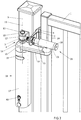
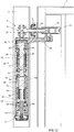
- the gate 1 shown in figure 1 is hingedly suspended at the top and at the bottom (not shown) from a support 3, more specifically from a pole, by means of a height adjustable eyebolt hinge 2.
- the eyebolt hinge 2 is a hinge as described in EP-B-1 528 202 or in EP-A-2 778 331 .
- a rail 4 is welded against the lateral side of the gate.
- a slidable gliding piece 5 is provided, into which two bolts 6 are screwed. With these bolts 6, a fastening member 7 projecting from the front of the gate 1 is mounted onto the gate 1 at an adjustable height.
- the projecting fastening member 7 is provided with an elongated hole 8 for attaching the eyebolt 9 of the eyebolt hinge 2.
- an elongated hole 8 for attaching the eyebolt 9 of the eyebolt hinge 2.
- Such an embodiment is shown in figure 10 .
- the eyebolt hinge 2 comprises a U-shaped hinge element 10 that is attached to the front of the pole 3, particularly by welding. On this hinge element 10, a hinge pin 11 is provided.
- the eyebolt 9 has an eye portion 12 that is hinged according to a hinge axis 13 onto the hinge pin 11.
- the eyebolt 9 further comprises a bolt portion 14 extending through the elongated hole 8 in the projecting fastening member 7.
- the bolt portion 14 of the eyebolt 9 thus has a portion that projects from the fastening member 7 of the gate over a distance, and that comprises the free end of the eyebolt.
- two adjustment nuts 15 are screwed onto the bolt portion 14 of the eyebolt 9 on either side of said fastening member 7, between which the projecting fastening member 7 is clamped.
- the adjustment nuts 15 allow the distance from the gate 1 to the pole 3 to be adjusted, whereby the distance over which the bolt portion 14 of the eyebolt projects from the fastening member 7 also varies.
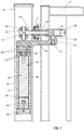
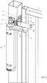
- the gate closer 16 comprises a body 17, an actuating arm 18 which is mounted rotatably according to a first rotational axis 19 onto the body 17 of the gate closer 16, an actuator 20, shown in figure 7 , in the body 17 for actuating the rotating actuating arm 18 and a coupling mechanism 21 for coupling the actuating arm 18 to the bolt portion 14 of the eyebolt 9.
- the body 17 of the gate closer 16 is configured to be mounted below the eyebolt hinge 2 onto the pole 3 with the rotational axis 19 of the actuating arm 18 substantially parallel to, and preferably substantially in line with the hinge axis 13 of the eyebolt hinge 2.
- the gate closer 16 can also be mounted onto the support above this lower eyebolt hinge 2.
- the gate closer 16 can also be mounted onto the support 3 above the upper eyebolt hinge 2 when the support projects a sufficient distance above the upper eyebolt hinge 2.
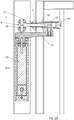
- the coupling mechanism 21 comprises an inner sleeve 22 arranged to be screwed onto the projecting portion of said bolt portion 14 over the free end of the bolt portion 14 of the eyebolt 9, and a cylindrical outer sleeve 23 arranged on the inner sleeve 22 so as to be slidable back and forth in the longitudinal direction of the bolt portion 14 of the eyebolt 9.
- the outer sleeve 23 has a cylindrical inner casing and the inner sleeve 22 has a cylindrical outer casing, wherein the inner casing of the outer sleeve 23 fits with some clearance around the outer casing of the inner sleeve 22.
- the outer sleeve 23 is further mounted onto the actuating arm 18 so as to be rotatable around a second rotational axis 24, which is parallel to the first rotational axis 19.
- the actuating arm 18 is thereto provided, at its free end, with a vertical opening 25, and the outer sleeve is provided with a protrusion 26 that fits in the opening 25 and that can rotate therein according to the second rotational axis 24.
- Both the opening 25 and the protrusion 26 are preferably cylindrical.
- a bolt 27 is screwed into the free end of the protrusion 26.
- the outer sleeve 23 has an open end that can be closed by means of a screwable cap 28.
- a hexagonal cavity for an Allan key is provided, by means of which both can be screwed tight.
- the hexagonal cavity in the screwable cap 28 is drilled out after screwing it tight, making the cavity cylindrical. In that way, the inner sleeve 22 can no longer be unscrewed, or can only partly be unscrewed, with the coupling mechanism always remaining attached on the eyebolt. A potential burglar can thus no longer detach the gate 1 from the support.
- the inner sleeve 22 preferably has a length so as to be screwable over the free end of the eyebolt 9 up against one of the two adjustment nuts 15. Not only does this allow the inner sleeve 22 to be fixed onto the bolt portion 14 of the eyebolt 9, by screwing the inner sleeve 22 sufficiently tight, but the inner sleeve 22 also provides a strengthening of the projecting portion of the eyebolt 9. In this way, the eyebolt 9 can better resist the considerable forces exerted onto it by the gate closer 16.
- the outer sleeve 23 herein preferably has an inner diameter that is preferably at least 15%, and more preferably at least 20% greater than the outer diameter of the bolt portion 14 of the eyebolt 9. The greater this difference in diameter, the further the outer sleeve 23 can be tilted over the eyebolt 9, and thus, the stronger the connection between both.
- the actuating arm 18 first of all needs to be of sufficient length. If the free end of the eyebolt 9 is located at a distance 29 (indicated in figure 8 ) from the hinge axis 13, and the second rotational axis 24 is at a first distance 30 from the first rotational axis 19, this first distance 30 needs to be sufficiently large when compared to the distance 29, wherein, however, the first distance does not always need to be larger than the distance 29 but may also be somewhat smaller.
- the first distance 30 is smaller than the distance between the hinge axis 13 and the free end of the eyebolt 9 plus the inner diameter of the outer sleeve 23.
- the second distance 31, being the distance 31 between the second rotational axis 24 and the free end of the outer sleeve 23 which is installed over the eyebolt 9, measured along the longitudinal direction of the outer sleeve 23, should be sufficiently small for the outer sleeve 23 to be tiltable onto the eyebolt 9 by rotating the actuating arm 18 around the first rotational axis 19 and rotating the outer sleeve 23 around the second rotational axis 24.
- the second distance 31 should preferably be chosen to be sufficiently large for the distance over which the outer sleeve 23 extends over the eyebolt 9, hereafter called third distance 32, to be sufficiently large.
- this third distance 32 i.e. the distance of the overlap between the outer sleeve 23 and the eyebolt 9 is important.
- this distance 32 is larger when the rotational axis 24 of the outer sleeve 23 is at a larger second distance 31 from the free end of the outer sleeve 23.
- the first distance 30 is preferably chosen to be sufficiently small, and the second distance 31 to be sufficiently large, so that when the gate closer 16 is mounted below the eyebolt hinge 2 with the first rotational axis 19 in line with the hinge axis 13, the third distance 32 is at least 45%, preferably at least 50% and more preferably at least 55% of the inner diameter of the outer sleeve 23.
- the first distance 30 is about 80% of the inner diameter of the outer sleeve 23 larger than the distance 29 between the hinge axis 13 and the free end of the eyebolt 9, and the second distance is about 143% of the inner diameter of the outer sleeve 23.
- the third distance 32 is substantially 60% of the inner diameter of the outer sleeve 23.
- the outer sleeve 23 can slide along its longitudinal direction over the inner sleeve 22, it remains possible to adjust the distance between the gate 1 and the support 3 by means of the eyebolt 9. In figure 7 , for instance, the gate is closer to the support 3 than in figure 9 . It is important to note that the distance 32 over which the outer sleeve 23 overlaps with the eyebolt 9 always remains the same. The strength of the coupling mechanism 21 thus also remains the same.
- the sliding connecting between both sleeves 22, 23 further offers the advantage that the gate closer 16 does not need to be mounted correctly onto the support 3 below the eyebolt hinge 2, with the rotational axis 19 of the actuating arm 18 in line with the hinge axis 13. Even if both axes are not in line with each other, the gate closer can function correctly.
- the actuator 20 provided inside the gate closer 16 may, as shown in figures 7 to 10 , comprise a motor, or, as shown in figure 12 , a spring mechanism.
- the motor may be a hydraulic motor, but an electric motor is preferred due to its compactness.
- an electric motor 33 is shown schematically inside the body 17 of the gate closer 16.
- This electric motor 33 comprises a motor body 34 with the coils required for actuating a rotating driving axis 35.
- This driving axis 35 extends at the top inside the actuating arm 18 of the gate closer to rotate it around the first rotational axis 19.
- the actuating arm 18 is mounted at the top in the body 17 of the gate closer 16 by means of a double ball bearing 36 so that it can rotate around the first rotational axis 19.
- the body 17 of the gate closer 16 is screwed onto the support 3 by means of two bolts 37 at the top and a third bolt 38.
- the motor body 34 has a cylindrical outer casing which fits into a cylindrical space in the body 17 of the gate closer 16. This way, the motor body 34 can be rotated in the body 17 of the gate closer 16. However, for actuating the actuating arm 18 it is required that the motor body 34 is locked in the body 17 of the gate closer 16.
- a locking mechanism 39 with a lock cylinder 40 is provided. By means of this locking mechanism 39 the motor body 34 can be locked or unlocked using a key. This allows the gate 1 to be opened manually, for instance during an electrical power failure.
- the gate By means of the motor, the gate can be both opened and closed.
- the motor is further provided with a control by means of which the resting position of the actuating arm 18 can be set. This allows the gate closer to be used both for a left-turning gate and for a right-turning gate.
- the gate closer shown in figure 12 does not have motor as its actuator 20 but a spring 41, more specifically a torsion spring. When opening the gate 1, this spring 41 is tensioned, and when closing the gate 1 the spring 41 causes the automatic closing of the gate 1.
- the gate closer further comprises a hydraulic damper 42 dampening the closing movement of the gate.
- the hydraulic damper 42 comprises a cylinder 43 divided into two chambers by means of a piston 44.
- the damper 42 is provided with a one-way valve that allows the hydraulic liquid to flow from one chamber to the other when opening the gate. When closing the gate, the valve is closed and the hydraulic liquid can only flow back to the other chamber through a narrow passage.
- the actuating arm 18 of the gate closer 16 is mounted at the top onto a shaft 46 extending throughout the gate closer 16 by means of a pin 45. Both at the top and at the bottom a double bearing 47, 48 is provided between the shaft 46 and the body 17 of the gate closer, so that the actuating arm is again mounted onto the body 17 of the gate closer 16 by means of a double ball bearing.
- the actuating arm 18 can be mounted in a similar way onto the shaft 46 by means of the pin 45.
- the gate closer 16 can be mounted onto the support 3 in two vertical positions, namely in one position for a left-turning gate and in the reversed position for a right-turning gate.
- the body 17 of the gate closer 16 is attached to the support 3 by means of two bolts 49, 50.
- the upper end of the torsion spring 41 is attached to the body 17 of the gate closer 16, while the bottom end of the torsion spring 41 is attached to the shaft 46, more specifically by intermediary of the pin 51.
- the bottom part of the body of the gate closer forms the cylinder 43 which is filled with a hydraulic liquid and sealed at the top and at the bottom by oil seals 52.
- a threaded sleeve 53 is fixed to the shaft 43 by means of a pin 54.
- the piston 44 itself is provided at the top with an internally threaded sleeve 55 screwed onto the sleeve 53 of the shaft 46. Because the piston 44 cannot rotate inside the cylinder 43, a rotating motion of the shaft 46 causes an upward and downward motion of the piston 44.
- a one-way valve is provided in the piston 44 (not shown in figure 12 ) which ensures that the hydraulic damper 42 provides substantially no dampening when opening the gate.
- a small channel 56 is provided which connects the upper chamber of the cylinder 43 to its bottom chamber.
- an adjustment screw 57 is screwed into this channel 56.
- the adjustment screw 57 is more specifically provided with a needle 58 that forms a needle valve by means of which the flow rate of the hydraulic liquid through het channel 56, or i.o.w. the dampening effect of the hydraulic damper 42, can be adjusted.
Landscapes
- Hinges (AREA)
- Gates (AREA)
- Closing And Opening Devices For Wings, And Checks For Wings (AREA)
Claims (20)
- Dispositif de fermeture de porte, adapté pour être installé sur une porte (1) qui est suspendu de manière articulée sur un côté d'un support (3) au moyen d'une charnière à boulon à œil (2), dans lequel ladite charnière à boulon à œil (2) comprend un élément de charnière (10) monté sur ledit côté du support (3), un goujon de charnière (11) disposé sur ledit élément de charnière (10) et un boulon à œil (9), ledit boulon à œil (9) ayant une partie d'œil (12) qui est articulée sur ledit élément de charnière (10) autour dudit goujon de charnière (11) selon un axe de charnière (13), et une partie de boulon (14) s'étendant à travers un élément de fixation (7) sur la porte (1) faisant saillie depuis ledit côté de la porte (1), dans lequel la partie de boulon (14) du boulon à œil (9) a une partie en saillie ayant une extrémité libre et faisant saillie sur le côté de l'élément de fixation (7) faisant face à l'écart dudit goujon de charnière (11) sur une distance de l'élément de fixation (7) de la porte (1), et dans lequel ledit élément de fixation (7) est serré entre deux écrous de réglage (15) sur la partie de boulon (14) du boulon à œil (9), lesquels écrous de réglage (15) sont disposés pour régler la distance sur laquelle la partie de boulon (14) du boulon à œil (9) fait saillie, et ainsi la distance entre la porte (1) et le support (3),ledit dispositif de fermeture de porte (16) comprenant un corps (17), un bras d'actionnement (18) qui est monté de manière rotative selon un premier axe de rotation (19) sur ledit corps (17), un actionneur (20) dans ledit corps pour actionner le bras d'actionnement rotatif (18) et un mécanisme de couplage (21) pour coupler le bras d'actionnement (18) à la partie de boulon (14) du boulon à œil (9), dans lequel le corps (17) du dispositif de fermeture de porte (16) est configuré pour être monté sous ladite charnière à boulon à œil (2) sur ledit support (3) avec ledit premier axe de rotation (19) sensiblement parallèle audit axe de charnière (13),caractérisé en ce queledit mécanisme de couplage (21) comprend un manchon interne (22) agencé pour être vissé sur l'extrémité libre de la partie de boulon (14) du boulon à œil (9) sur la partie en saillie de ladite partie de boulon (14), et un manchon externe (23) qui est monté sur le manchon interne (22) de manière à pouvoir coulisser en arrière et en avant dans la direction longitudinale de la partie de boulon (14) du boulon à œil (9), et qui est monté de manière rotative autour d'un second axe de rotation (24), qui est parallèle audit premier axe de rotation (19), sur le bras d'actionnement (18).
- Dispositif de fermeture de porte selon la revendication 1, caractérisé en ce que ledit manchon externe (23) a une extrémité ouverte, permettant au manchon interne (22) d'être vissé à travers le manchon externe (23) sur la partie en saillie du boulon à œil (9).
- Dispositif de fermeture de porte selon la revendication 2, caractérisé en ce que l'extrémité ouverte du manchon externe (23) est fermée au moyen d'un capuchon vissable (28).
- Dispositif de fermeture de porte selon l'une quelconque des revendications 1 à 3, caractérisé en ce que ledit manchon interne (22) a une longueur telle qu'il peut être vissé sur l'extrémité libre du boulon à œil (9) jusqu'à l'un des deux écrous de réglage (15).
- Dispositif de fermeture de porte selon l'une quelconque des revendications 1 à 3, caractérisé en ce que ledit manchon interne (22) a une longueur telle qu'il peut être vissé sur l'extrémité libre du boulon à œil (9) jusqu'à l'élément de fixation en saillie (7), en remplacement un des deux écrous de réglage (15).
- Dispositif de fermeture de porte selon l'une quelconque des revendications 1 à 5, caractérisé en ce que ledit manchon externe (23) a un diamètre interne et une extrémité libre agencée pour être installée sur la partie en saillie du boulon à œil (9), en ce que ledit second axe de rotation (24) est situé à une première distance (30) dudit premier axe de rotation (19), et en ce que ledit second axe de rotation (24) est situé à une seconde distance (31), mesurée dans la direction longitudinale du manchon externe (23), de l'extrémité libre du manchon externe (23), dans lequel ledit diamètre interne, ladite première distance (30) et ladite seconde distance (31) sont déterminés de sorte que, lorsque le dispositif de fermeture de porte (16) est monté sous la charnière à boulon à œil (2) avec ledit premier axe de rotation (19) en ligne avec l'axe de charnière (13), ledit manchon externe (23) peut être monté ou retiré sur la partie en saillie du boulon à œil (9) en l'absence du manchon interne (22), en faisant tourner le bras d'actionnement (18) autour dudit premier axe de rotation (19) et en faisant tourner le manchon externe (23) autour dudit second axe de rotation (24).
- Dispositif de fermeture de porte selon la revendication 6, caractérisé en ce que ladite première distance (30) et ladite seconde distance (31) sont déterminées de sorte que, lorsque le dispositif de fermeture de porte (16) est monté sous la charnière à boulon à œil (2) avec ledit premier axe de rotation (19) en ligne avec l'axe de charnière (13), ledit manchon externe (23) chevauche le boulon à œil (9) sur une troisième distance (32), laquelle troisième distance est au moins 45 %, de préférence au moins 50 % et plus préférablement au moins 55 % du diamètre interne du manchon externe (23).
- Dispositif de fermeture de porte selon la revendication 6 ou 7, caractérisé en ce que ladite première distance (30) est inférieure à la distance entre l'axe de charnière (13) et l'extrémité libre du boulon à œil (9) plus le diamètre interne du manchon externe (23).
- Dispositif de fermeture de porte selon l'une quelconque des revendications 1 à 8, caractérisé en ce que la partie de boulon (14) du boulon à œil (9) a un diamètre externe et ledit manchon externe (23) a un diamètre interne qui est supérieur d'au moins 15 %, de préférence d'au moins 20 %, au diamètre externe de la partie de boulon (14) du boulon à œil (9).
- Dispositif de fermeture de porte selon l'une quelconque des revendications 1 à 9, caractérisé en ce que ledit actionneur (20) comprend un moteur (33), notamment un moteur électrique ou un moteur hydraulique.
- Dispositif de fermeture de porte selon la revendication 10, caractérisé en ce que ledit moteur (33) est agencé pour faire tourner ledit bras d'actionnement (18) dans les deux directions pour ouvrir et pour fermer ladite porte (1).
- Dispositif de fermeture de porte selon la revendication 10 ou 11, caractérisé en ce que ledit moteur (33) est verrouillé dans le corps (17) du dispositif de fermeture de porte (16) au moyen d'un mécanisme de verrouillage (39) et en ce que le moteur (33) peut être déverrouillé au moyen de ce mécanisme de verrouillage (39) pour permettre au bras d'actionnement (18) d'être tourné manuellement.
- Dispositif de fermeture de porte selon l'une quelconque des revendications 1 à 9, caractérisé en ce que ledit actionneur (20) comprend un ressort (41) agencé pour solliciter ledit bras d'actionnement (18) dans une direction pour fermer ladite porte (1), et pour être tendu lors de la rotation du bras d'actionnement (18) dans l'autre direction, lors de l'ouverture de la porte (1).
- Dispositif de fermeture de porte selon l'une quelconque des revendications 1 à 13, caractérisé en ce que ledit bras d'actionnement (18) est monté sur le corps (17) du dispositif de fermeture de porte (16) au moyen d'un double roulement à billes (36, 47).
- Dispositif de fermeture de porte selon l'une quelconque des revendications 1 à 14, caractérisé en ce que le corps (17) du dispositif de fermeture de porte (16) est configuré pour être monté sur ledit support (3) avec ledit premier axe de rotation (19) sensiblement aligné comme un prolongement dudit axe de charnière (13).
- Dispositif de fermeture de porte selon l'une quelconque des revendications 1 à 15, caractérisé en ce que le bras d'actionnement (18) est muni d'une ouverture (25) et le manchon externe (23) est muni d'une saillie (26) qui s'adapte à l'intérieur de ladite ouverture (25) et peut y tourner selon ledit second axe de rotation (24).
- Dispositif de fermeture de porte selon la revendication 16, caractérisé en ce que ladite saillie (26) a une extrémité libre dans laquelle un boulon (27) est vissé pour fixer ladite saillie (26) dans ladite ouverture (25).
- Dispositif de fermeture de porte selon l'une quelconque des revendications 1 à 17, caractérisé en ce que ledit manchon interne (22) a une enveloppe extérieure cylindrique et ledit manchon externe (23) a une enveloppe interne cylindrique.
- Porte, muni d'un dispositif de fermeture de porte, dans laquelle ladite porte (1) est montée de manière articulée sur un côté d'un support (3) au moyen d'une charnière à boulon à œil (2), dans laquelle ladite charnière à boulon à œil (2) comprend un élément de charnière (10) monté sur ledit côté du support (3), un goujon de charnière (11) disposé sur ledit élément de charnière (10) et un boulon à œil (9), lequel boulon à œil (9) a une partie d'œil (12) qui est articulée sur ledit élément de charnière (10) autour dudit goujon de charnière (10) selon un axe de charnière (13), et une partie de boulon (14) s'étendant à travers un élément de fixation (7) sur la porte (1) faisant saillie depuis ledit côté de la porte (1), dans laquelle la partie de boulon (14) du boulon à œil (9) a une partie en saillie ayant une extrémité libre et faisant saillie sur le côté de l'élément de fixation (7) faisant face à l'écart dudit goujon de charnière (11) sur une distance de l'élément de fixation (7) de la porte (1), et dans laquelle ledit élément de fixation (7) est serré entre deux écrous de réglage (15) sur la partie de boulon (14) du boulon à œil (9), lesquels écrous de réglage (15) sont disposés pour régler la distance sur laquelle la partie de boulon (14) du boulon à œil (9) fait saillie, et ainsi la distance entre la porte (1) et le support (3),lequel dispositif de fermeture de porte (16) comprend un corps (17), un bras d'actionnement (18) qui est monté de manière rotative selon un premier axe de rotation (13) sur ledit corps (17), un actionneur (20) dans ledit corps (17) pour actionner le bras d'actionnement rotatif (18) et un mécanisme de couplage (21) pour coupler le bras d'actionnement (18) à la partie de boulon (14) du boulon à œil (9), dans laquelle le corps (17) du dispositif de fermeture de porte (16) est configuré pour être monté au-dessous ou au-dessus de ladite charnière à boulon à œil (2) sur ledit support (3) avec ledit premier axe de rotation (19) parallèle audit axe de charnière (13),caractérisée en ce queledit mécanisme de couplage (21) comprend un manchon interne (22) vissé sur ladite partie de boulon (14) sur l'extrémité libre de la partie de boulon (14) du boulon à œil (9), et un manchon externe (23) qui est monté sur le manchon interne (22) de manière à pouvoir coulisser en arrière et en avant dans la direction longitudinale de la partie de boulon (14) du boulon à œil (9), et qui est monté sur le bras d'actionnement (18) pour pouvoir tourner autour d'un second axe de rotation (24), qui est parallèle audit premier axe de rotation (19).
- Porte selon la revendication 19, caractérisée en ce que ledit dispositif de fermeture de porte (16) présente les caractéristiques selon l'une quelconque des revendications 2 à 18.
Priority Applications (1)
| Application Number | Priority Date | Filing Date | Title |
|---|---|---|---|
| PL18765601T PL3679215T3 (pl) | 2017-09-05 | 2018-08-31 | Samozamykacz bramy przystosowany do zamontowania na bramie z zawiasem ze śrubą oczkową |
Applications Claiming Priority (2)
| Application Number | Priority Date | Filing Date | Title |
|---|---|---|---|
| BE2017/5629A BE1025032B1 (nl) | 2017-09-05 | 2017-09-05 | Poortsluiter geschikt om op een poort met een oogboutscharnier geretrofit te worden |
| PCT/EP2018/073522 WO2019048359A1 (fr) | 2017-09-05 | 2018-08-31 | Dispositif de fermeture de porte pouvant être adapté sur une porte avec une charnière à boulon à œil |
Publications (2)
| Publication Number | Publication Date |
|---|---|
| EP3679215A1 EP3679215A1 (fr) | 2020-07-15 |
| EP3679215B1 true EP3679215B1 (fr) | 2021-09-15 |
Family
ID=59982205
Family Applications (1)
| Application Number | Title | Priority Date | Filing Date |
|---|---|---|---|
| EP18765601.2A Active EP3679215B1 (fr) | 2017-09-05 | 2018-08-31 | Ferme-porte adapté pour être monté ultérieurement sur un portail avec une charnière à boulon à oeil |
Country Status (6)
| Country | Link |
|---|---|
| EP (1) | EP3679215B1 (fr) |
| BE (1) | BE1025032B1 (fr) |
| DK (1) | DK3679215T3 (fr) |
| ES (1) | ES2896700T3 (fr) |
| PL (1) | PL3679215T3 (fr) |
| WO (1) | WO2019048359A1 (fr) |
Cited By (2)
| Publication number | Priority date | Publication date | Assignee | Title |
|---|---|---|---|---|
| WO2025073950A1 (fr) * | 2023-10-05 | 2025-04-10 | Locinox | Actionneur de porte |
| BE1032034B1 (nl) * | 2023-10-05 | 2025-05-12 | Locinox Nv | Een poortactuator |
Families Citing this family (11)
| Publication number | Priority date | Publication date | Assignee | Title |
|---|---|---|---|---|
| CN110593218B (zh) * | 2019-09-18 | 2024-08-16 | 中铁第五勘察设计院集团有限公司 | 一种双向挡水闸 |
| CN117072005A (zh) * | 2022-05-09 | 2023-11-17 | 布勒(无锡)商业有限公司 | 铰链装置及设备组件 |
| EP4400684A1 (fr) | 2023-01-13 | 2024-07-17 | Locinox | Ferme-porte et système de fermeture le comprenant |
| BE1032039B1 (nl) | 2023-10-05 | 2025-05-12 | Locinox Nv | Een poortactuator en een sluitsysteem omvattende hetzelfde |
| BE1032033B1 (nl) | 2023-10-05 | 2025-05-12 | Locinox Nv | Een poortactuator |
| BE1032121B1 (nl) | 2023-11-08 | 2025-06-10 | Locinox Nv | Een poortactuator |
| BE1032036B1 (nl) | 2023-10-05 | 2025-05-12 | Locinox Nv | Een poortactuator |
| EP4610454A1 (fr) | 2024-03-01 | 2025-09-03 | Locinox | Poteau de portail |
| EP4610453A1 (fr) | 2024-03-01 | 2025-09-03 | Locinox | Poteau de portail |
| EP4610468A1 (fr) | 2024-03-01 | 2025-09-03 | Locinox | Poteau de portail |
| EP4667697A1 (fr) | 2024-06-17 | 2025-12-24 | Locinox | Actionneur de grille électrique et système de fermeture le comprenant |
Family Cites Families (3)
| Publication number | Priority date | Publication date | Assignee | Title |
|---|---|---|---|---|
| BE1015758A3 (nl) | 2003-10-31 | 2005-08-02 | Talpe Joseph | Mechanisme voor het op een instelbare hoogte aan een steun ophangen van een poort. |
| EP2778331A1 (fr) | 2013-03-11 | 2014-09-17 | Joseph Talpe | Ensemble de charnière |
| EP3162996A1 (fr) * | 2015-10-30 | 2017-05-03 | Locinox | Dispositif de fermeture d'un élément de fermeture monté articulé sur un support |
-
2017
- 2017-09-05 BE BE2017/5629A patent/BE1025032B1/nl active IP Right Grant
-
2018
- 2018-08-31 DK DK18765601.2T patent/DK3679215T3/da active
- 2018-08-31 WO PCT/EP2018/073522 patent/WO2019048359A1/fr not_active Ceased
- 2018-08-31 PL PL18765601T patent/PL3679215T3/pl unknown
- 2018-08-31 ES ES18765601T patent/ES2896700T3/es active Active
- 2018-08-31 EP EP18765601.2A patent/EP3679215B1/fr active Active
Cited By (2)
| Publication number | Priority date | Publication date | Assignee | Title |
|---|---|---|---|---|
| WO2025073950A1 (fr) * | 2023-10-05 | 2025-04-10 | Locinox | Actionneur de porte |
| BE1032034B1 (nl) * | 2023-10-05 | 2025-05-12 | Locinox Nv | Een poortactuator |
Also Published As
| Publication number | Publication date |
|---|---|
| BE1025032B1 (nl) | 2018-10-03 |
| EP3679215A1 (fr) | 2020-07-15 |
| ES2896700T3 (es) | 2022-02-25 |
| RU2020112499A3 (fr) | 2022-01-10 |
| PL3679215T3 (pl) | 2022-01-24 |
| RU2020112499A (ru) | 2021-10-06 |
| WO2019048359A1 (fr) | 2019-03-14 |
| DK3679215T3 (da) | 2021-10-25 |
Similar Documents
| Publication | Publication Date | Title |
|---|---|---|
| EP3679215B1 (fr) | Ferme-porte adapté pour être monté ultérieurement sur un portail avec une charnière à boulon à oeil | |
| US20170122019A1 (en) | Device for closing a closure member hinged onto a support | |
| US9725940B2 (en) | Door hinge closing mechanism | |
| US20180010376A1 (en) | Hinge | |
| JP2009531575A (ja) | ゲート支持装置 | |
| CN102292511A (zh) | 门用铰链装置 | |
| US9416572B2 (en) | Adjustable swing-controlled hinge | |
| CN107567528A (zh) | 具有主驱动器和辅助驱动器的门驱动装置 | |
| KR101997196B1 (ko) | 댐핑력 조절이 가능한 플로어 힌지장치 | |
| PT1605126E (pt) | Dispositivo de fecho de portas | |
| US20200370352A1 (en) | Improvements in damped hinge assemblies | |
| CN106460432A (zh) | 用于门的轴承组件 | |
| EA017972B1 (ru) | Регулируемая угловая опора для створки окна, двери или т.п. | |
| KR20060100016A (ko) | 도어의 힌지축 제어장치 | |
| CA3020835C (fr) | Bras de chargement d'extremite | |
| RU2772699C2 (ru) | Закрывающий механизм для ворот, выполненный с возможностью установки на ворота с петлей с рым-болтом | |
| KR200338218Y1 (ko) | 도어 개폐 완충기의 텐션 조절장치 | |
| KR200373610Y1 (ko) | 도어 완충기의 텐션 조절장치 | |
| GB2420587A (en) | Biased door hinge in combination with a dampened door hinge | |
| KR200397642Y1 (ko) | 도어 경첩용 힌지 브래킷 | |
| CA2058965C (fr) | Ferme-porte | |
| CN110965869A (zh) | 一种外开手柄总成装配组件 | |
| GB2145769A (en) | Door closers | |
| US2187109A (en) | Door closer | |
| CN101839107A (zh) | 带有闭门控速装置并能门停的安全门 |
Legal Events
| Date | Code | Title | Description |
|---|---|---|---|
| STAA | Information on the status of an ep patent application or granted ep patent |
Free format text: STATUS: UNKNOWN |
|
| STAA | Information on the status of an ep patent application or granted ep patent |
Free format text: STATUS: THE INTERNATIONAL PUBLICATION HAS BEEN MADE |
|
| PUAI | Public reference made under article 153(3) epc to a published international application that has entered the european phase |
Free format text: ORIGINAL CODE: 0009012 |
|
| STAA | Information on the status of an ep patent application or granted ep patent |
Free format text: STATUS: REQUEST FOR EXAMINATION WAS MADE |
|
| 17P | Request for examination filed |
Effective date: 20200327 |
|
| AK | Designated contracting states |
Kind code of ref document: A1 Designated state(s): AL AT BE BG CH CY CZ DE DK EE ES FI FR GB GR HR HU IE IS IT LI LT LU LV MC MK MT NL NO PL PT RO RS SE SI SK SM TR |
|
| AX | Request for extension of the european patent |
Extension state: BA ME |
|
| DAV | Request for validation of the european patent (deleted) | ||
| DAX | Request for extension of the european patent (deleted) | ||
| GRAP | Despatch of communication of intention to grant a patent |
Free format text: ORIGINAL CODE: EPIDOSNIGR1 |
|
| STAA | Information on the status of an ep patent application or granted ep patent |
Free format text: STATUS: GRANT OF PATENT IS INTENDED |
|
| INTG | Intention to grant announced |
Effective date: 20210429 |
|
| GRAS | Grant fee paid |
Free format text: ORIGINAL CODE: EPIDOSNIGR3 |
|
| GRAA | (expected) grant |
Free format text: ORIGINAL CODE: 0009210 |
|
| STAA | Information on the status of an ep patent application or granted ep patent |
Free format text: STATUS: THE PATENT HAS BEEN GRANTED |
|
| AK | Designated contracting states |
Kind code of ref document: B1 Designated state(s): AL AT BE BG CH CY CZ DE DK EE ES FI FR GB GR HR HU IE IS IT LI LT LU LV MC MK MT NL NO PL PT RO RS SE SI SK SM TR |
|
| REG | Reference to a national code |
Ref country code: CH Ref legal event code: EP |
|
| REG | Reference to a national code |
Ref country code: DE Ref legal event code: R096 Ref document number: 602018023663 Country of ref document: DE |
|
| REG | Reference to a national code |
Ref country code: IE Ref legal event code: FG4D |
|
| REG | Reference to a national code |
Ref country code: AT Ref legal event code: REF Ref document number: 1430653 Country of ref document: AT Kind code of ref document: T Effective date: 20211015 |
|
| REG | Reference to a national code |
Ref country code: DK Ref legal event code: T3 Effective date: 20211021 |
|
| REG | Reference to a national code |
Ref country code: NL Ref legal event code: FP |
|
| REG | Reference to a national code |
Ref country code: LT Ref legal event code: MG9D |
|
| PG25 | Lapsed in a contracting state [announced via postgrant information from national office to epo] |
Ref country code: SE Free format text: LAPSE BECAUSE OF FAILURE TO SUBMIT A TRANSLATION OF THE DESCRIPTION OR TO PAY THE FEE WITHIN THE PRESCRIBED TIME-LIMIT Effective date: 20210915 Ref country code: RS Free format text: LAPSE BECAUSE OF FAILURE TO SUBMIT A TRANSLATION OF THE DESCRIPTION OR TO PAY THE FEE WITHIN THE PRESCRIBED TIME-LIMIT Effective date: 20210915 Ref country code: HR Free format text: LAPSE BECAUSE OF FAILURE TO SUBMIT A TRANSLATION OF THE DESCRIPTION OR TO PAY THE FEE WITHIN THE PRESCRIBED TIME-LIMIT Effective date: 20210915 Ref country code: FI Free format text: LAPSE BECAUSE OF FAILURE TO SUBMIT A TRANSLATION OF THE DESCRIPTION OR TO PAY THE FEE WITHIN THE PRESCRIBED TIME-LIMIT Effective date: 20210915 Ref country code: LT Free format text: LAPSE BECAUSE OF FAILURE TO SUBMIT A TRANSLATION OF THE DESCRIPTION OR TO PAY THE FEE WITHIN THE PRESCRIBED TIME-LIMIT Effective date: 20210915 Ref country code: BG Free format text: LAPSE BECAUSE OF FAILURE TO SUBMIT A TRANSLATION OF THE DESCRIPTION OR TO PAY THE FEE WITHIN THE PRESCRIBED TIME-LIMIT Effective date: 20211215 Ref country code: NO Free format text: LAPSE BECAUSE OF FAILURE TO SUBMIT A TRANSLATION OF THE DESCRIPTION OR TO PAY THE FEE WITHIN THE PRESCRIBED TIME-LIMIT Effective date: 20211215 |
|
| REG | Reference to a national code |
Ref country code: AT Ref legal event code: MK05 Ref document number: 1430653 Country of ref document: AT Kind code of ref document: T Effective date: 20210915 |
|
| REG | Reference to a national code |
Ref country code: ES Ref legal event code: FG2A Ref document number: 2896700 Country of ref document: ES Kind code of ref document: T3 Effective date: 20220225 |
|
| PG25 | Lapsed in a contracting state [announced via postgrant information from national office to epo] |
Ref country code: LV Free format text: LAPSE BECAUSE OF FAILURE TO SUBMIT A TRANSLATION OF THE DESCRIPTION OR TO PAY THE FEE WITHIN THE PRESCRIBED TIME-LIMIT Effective date: 20210915 Ref country code: GR Free format text: LAPSE BECAUSE OF FAILURE TO SUBMIT A TRANSLATION OF THE DESCRIPTION OR TO PAY THE FEE WITHIN THE PRESCRIBED TIME-LIMIT Effective date: 20211216 |
|
| PG25 | Lapsed in a contracting state [announced via postgrant information from national office to epo] |
Ref country code: AT Free format text: LAPSE BECAUSE OF FAILURE TO SUBMIT A TRANSLATION OF THE DESCRIPTION OR TO PAY THE FEE WITHIN THE PRESCRIBED TIME-LIMIT Effective date: 20210915 |
|
| PG25 | Lapsed in a contracting state [announced via postgrant information from national office to epo] |
Ref country code: IS Free format text: LAPSE BECAUSE OF FAILURE TO SUBMIT A TRANSLATION OF THE DESCRIPTION OR TO PAY THE FEE WITHIN THE PRESCRIBED TIME-LIMIT Effective date: 20220115 Ref country code: SM Free format text: LAPSE BECAUSE OF FAILURE TO SUBMIT A TRANSLATION OF THE DESCRIPTION OR TO PAY THE FEE WITHIN THE PRESCRIBED TIME-LIMIT Effective date: 20210915 Ref country code: SK Free format text: LAPSE BECAUSE OF FAILURE TO SUBMIT A TRANSLATION OF THE DESCRIPTION OR TO PAY THE FEE WITHIN THE PRESCRIBED TIME-LIMIT Effective date: 20210915 Ref country code: RO Free format text: LAPSE BECAUSE OF FAILURE TO SUBMIT A TRANSLATION OF THE DESCRIPTION OR TO PAY THE FEE WITHIN THE PRESCRIBED TIME-LIMIT Effective date: 20210915 Ref country code: PT Free format text: LAPSE BECAUSE OF FAILURE TO SUBMIT A TRANSLATION OF THE DESCRIPTION OR TO PAY THE FEE WITHIN THE PRESCRIBED TIME-LIMIT Effective date: 20220117 Ref country code: EE Free format text: LAPSE BECAUSE OF FAILURE TO SUBMIT A TRANSLATION OF THE DESCRIPTION OR TO PAY THE FEE WITHIN THE PRESCRIBED TIME-LIMIT Effective date: 20210915 Ref country code: CZ Free format text: LAPSE BECAUSE OF FAILURE TO SUBMIT A TRANSLATION OF THE DESCRIPTION OR TO PAY THE FEE WITHIN THE PRESCRIBED TIME-LIMIT Effective date: 20210915 Ref country code: AL Free format text: LAPSE BECAUSE OF FAILURE TO SUBMIT A TRANSLATION OF THE DESCRIPTION OR TO PAY THE FEE WITHIN THE PRESCRIBED TIME-LIMIT Effective date: 20210915 |
|
| REG | Reference to a national code |
Ref country code: DE Ref legal event code: R097 Ref document number: 602018023663 Country of ref document: DE |
|
| PLBE | No opposition filed within time limit |
Free format text: ORIGINAL CODE: 0009261 |
|
| STAA | Information on the status of an ep patent application or granted ep patent |
Free format text: STATUS: NO OPPOSITION FILED WITHIN TIME LIMIT |
|
| 26N | No opposition filed |
Effective date: 20220616 |
|
| PG25 | Lapsed in a contracting state [announced via postgrant information from national office to epo] |
Ref country code: SI Free format text: LAPSE BECAUSE OF FAILURE TO SUBMIT A TRANSLATION OF THE DESCRIPTION OR TO PAY THE FEE WITHIN THE PRESCRIBED TIME-LIMIT Effective date: 20210915 |
|
| PG25 | Lapsed in a contracting state [announced via postgrant information from national office to epo] |
Ref country code: MC Free format text: LAPSE BECAUSE OF FAILURE TO SUBMIT A TRANSLATION OF THE DESCRIPTION OR TO PAY THE FEE WITHIN THE PRESCRIBED TIME-LIMIT Effective date: 20210915 |
|
| REG | Reference to a national code |
Ref country code: CH Ref legal event code: PL |
|
| PG25 | Lapsed in a contracting state [announced via postgrant information from national office to epo] |
Ref country code: LU Free format text: LAPSE BECAUSE OF NON-PAYMENT OF DUE FEES Effective date: 20220831 Ref country code: LI Free format text: LAPSE BECAUSE OF NON-PAYMENT OF DUE FEES Effective date: 20220831 Ref country code: CH Free format text: LAPSE BECAUSE OF NON-PAYMENT OF DUE FEES Effective date: 20220831 |
|
| PG25 | Lapsed in a contracting state [announced via postgrant information from national office to epo] |
Ref country code: IE Free format text: LAPSE BECAUSE OF NON-PAYMENT OF DUE FEES Effective date: 20220831 |
|
| PG25 | Lapsed in a contracting state [announced via postgrant information from national office to epo] |
Ref country code: CY Free format text: LAPSE BECAUSE OF FAILURE TO SUBMIT A TRANSLATION OF THE DESCRIPTION OR TO PAY THE FEE WITHIN THE PRESCRIBED TIME-LIMIT Effective date: 20210915 |
|
| PG25 | Lapsed in a contracting state [announced via postgrant information from national office to epo] |
Ref country code: MK Free format text: LAPSE BECAUSE OF FAILURE TO SUBMIT A TRANSLATION OF THE DESCRIPTION OR TO PAY THE FEE WITHIN THE PRESCRIBED TIME-LIMIT Effective date: 20210915 Ref country code: HU Free format text: LAPSE BECAUSE OF FAILURE TO SUBMIT A TRANSLATION OF THE DESCRIPTION OR TO PAY THE FEE WITHIN THE PRESCRIBED TIME-LIMIT; INVALID AB INITIO Effective date: 20180831 |
|
| PG25 | Lapsed in a contracting state [announced via postgrant information from national office to epo] |
Ref country code: MT Free format text: LAPSE BECAUSE OF FAILURE TO SUBMIT A TRANSLATION OF THE DESCRIPTION OR TO PAY THE FEE WITHIN THE PRESCRIBED TIME-LIMIT Effective date: 20210915 |
|
| PGFP | Annual fee paid to national office [announced via postgrant information from national office to epo] |
Ref country code: NL Payment date: 20250723 Year of fee payment: 8 |
|
| PGFP | Annual fee paid to national office [announced via postgrant information from national office to epo] |
Ref country code: ES Payment date: 20250916 Year of fee payment: 8 |
|
| PGFP | Annual fee paid to national office [announced via postgrant information from national office to epo] |
Ref country code: DE Payment date: 20250827 Year of fee payment: 8 Ref country code: DK Payment date: 20250825 Year of fee payment: 8 |
|
| PGFP | Annual fee paid to national office [announced via postgrant information from national office to epo] |
Ref country code: PL Payment date: 20250812 Year of fee payment: 8 Ref country code: IT Payment date: 20250825 Year of fee payment: 8 |
|
| PGFP | Annual fee paid to national office [announced via postgrant information from national office to epo] |
Ref country code: BE Payment date: 20250723 Year of fee payment: 8 Ref country code: GB Payment date: 20250826 Year of fee payment: 8 |
|
| PGFP | Annual fee paid to national office [announced via postgrant information from national office to epo] |
Ref country code: FR Payment date: 20250723 Year of fee payment: 8 |
|
| PG25 | Lapsed in a contracting state [announced via postgrant information from national office to epo] |
Ref country code: TR Free format text: LAPSE BECAUSE OF FAILURE TO SUBMIT A TRANSLATION OF THE DESCRIPTION OR TO PAY THE FEE WITHIN THE PRESCRIBED TIME-LIMIT Effective date: 20210915 |