EP3679224B1 - Ausziehbarer ausleger einer bohranlage und bohranlage mit diesem ausziehbaren ausleger - Google Patents
Ausziehbarer ausleger einer bohranlage und bohranlage mit diesem ausziehbaren ausleger Download PDFInfo
- Publication number
- EP3679224B1 EP3679224B1 EP18740734.1A EP18740734A EP3679224B1 EP 3679224 B1 EP3679224 B1 EP 3679224B1 EP 18740734 A EP18740734 A EP 18740734A EP 3679224 B1 EP3679224 B1 EP 3679224B1
- Authority
- EP
- European Patent Office
- Prior art keywords
- hydraulic
- extendable boom
- conduit
- drilling machine
- boom
- Prior art date
- Legal status (The legal status is an assumption and is not a legal conclusion. Google has not performed a legal analysis and makes no representation as to the accuracy of the status listed.)
- Active
Links
Images
Classifications
-
- E—FIXED CONSTRUCTIONS
- E21—EARTH OR ROCK DRILLING; MINING
- E21B—EARTH OR ROCK DRILLING; OBTAINING OIL, GAS, WATER, SOLUBLE OR MELTABLE MATERIALS OR A SLURRY OF MINERALS FROM WELLS
- E21B7/00—Special methods or apparatus for drilling
- E21B7/02—Drilling rigs characterised by means for land transport with their own drive, e.g. skid mounting or wheel mounting
- E21B7/023—Drilling rigs characterised by means for land transport with their own drive, e.g. skid mounting or wheel mounting the mast being foldable or telescopically retractable
-
- E—FIXED CONSTRUCTIONS
- E21—EARTH OR ROCK DRILLING; MINING
- E21B—EARTH OR ROCK DRILLING; OBTAINING OIL, GAS, WATER, SOLUBLE OR MELTABLE MATERIALS OR A SLURRY OF MINERALS FROM WELLS
- E21B7/00—Special methods or apparatus for drilling
- E21B7/02—Drilling rigs characterised by means for land transport with their own drive, e.g. skid mounting or wheel mounting
-
- E—FIXED CONSTRUCTIONS
- E21—EARTH OR ROCK DRILLING; MINING
- E21B—EARTH OR ROCK DRILLING; OBTAINING OIL, GAS, WATER, SOLUBLE OR MELTABLE MATERIALS OR A SLURRY OF MINERALS FROM WELLS
- E21B7/00—Special methods or apparatus for drilling
- E21B7/02—Drilling rigs characterised by means for land transport with their own drive, e.g. skid mounting or wheel mounting
- E21B7/025—Rock drills, i.e. jumbo drills
-
- B—PERFORMING OPERATIONS; TRANSPORTING
- B66—HOISTING; LIFTING; HAULING
- B66C—CRANES; LOAD-ENGAGING ELEMENTS OR DEVICES FOR CRANES, CAPSTANS, WINCHES, OR TACKLES
- B66C13/00—Other constructional features or details
- B66C13/12—Arrangements of means for transmitting pneumatic, hydraulic, or electric power to movable parts of devices
- B66C13/14—Arrangements of means for transmitting pneumatic, hydraulic, or electric power to movable parts of devices to load-engaging elements or motors associated therewith
-
- B—PERFORMING OPERATIONS; TRANSPORTING
- B66—HOISTING; LIFTING; HAULING
- B66C—CRANES; LOAD-ENGAGING ELEMENTS OR DEVICES FOR CRANES, CAPSTANS, WINCHES, OR TACKLES
- B66C23/00—Cranes comprising essentially a beam, boom, or triangular structure acting as a cantilever and mounted for translatory of swinging movements in vertical or horizontal planes or a combination of such movements, e.g. jib-cranes, derricks, tower cranes
- B66C23/62—Constructional features or details
- B66C23/64—Jibs
- B66C23/70—Jibs constructed of sections adapted to be assembled to form jibs or various lengths
- B66C23/701—Jibs constructed of sections adapted to be assembled to form jibs or various lengths telescopic
- B66C23/705—Jibs constructed of sections adapted to be assembled to form jibs or various lengths telescopic telescoped by hydraulic jacks
-
- E—FIXED CONSTRUCTIONS
- E21—EARTH OR ROCK DRILLING; MINING
- E21B—EARTH OR ROCK DRILLING; OBTAINING OIL, GAS, WATER, SOLUBLE OR MELTABLE MATERIALS OR A SLURRY OF MINERALS FROM WELLS
- E21B7/00—Special methods or apparatus for drilling
- E21B7/02—Drilling rigs characterised by means for land transport with their own drive, e.g. skid mounting or wheel mounting
- E21B7/022—Control of the drilling operation; Hydraulic or pneumatic means for activation or operation
Definitions
- the invention relates to an extendable boom of a drill rig and to a drill rig comprising an extendable boom.
- hydraulic devices such as a rock drilling machines
- Such hydraulic devices often include several hydraulic components which need to be supplied with hydraulic fluid, and in some cases flushing medium and pressurised air also need to be supplied to the hydraulic device, such that additional conduits need to be provided along the movable arm.
- a rotation device for a boom of a mining or construction work rig is disclosed.
- the arrangement of WO 2006/096110 A1 comprises a hydraulic device in the form of a drilling machine.
- the hydraulic device therein is provided with hydraulic fluid via hoses arranged in flexible reel arrangements allowing the different parts of the rig arm arrangement to rotate and pivot with respect to each other.
- Such a system is problematic due to the fact that the hoses are exposed to the harsh environment of a mining or construction vehicle risking that a hose may rupture.
- a major part of the downtime of a mining or construction vehicle with a hydraulic device arranged on an arm that extends out from the vehicle is due to problems with the provision of hydraulic fluid in one way or another. Further, the many hoses may impede the visibility for the operator controlling the mining or construction vehicle.
- JP S60 4647 U relates to an earthmoving machine with a hydraulic cylinder arranged to govern extension of an extendable boom.
- An outer tube and an inner tube constitute the hydraulic conduits for feeding pressurized hydraulic fluid to hydraulic devices for actuating a bucket or a secondary boom.
- the hydraulic cylinder and the hydraulic conduits are arranged inside the extendable boom side by side, i.e. with the hydraulic conduits inside the extendable boom but outside of the hydraulic cylinder.
- US 3 664 527 A discloses a boom assembly of an earthmoving machine comprising a first and a second boom arms, the second boom arm being rotatable about the longitudinal axis of the boom assembly relative to the first boom arm.
- the first boom arm with two sections is extendable by means of a double acting hydraulic cylinder.
- Telescopic tubes are positioned within the boom assembly for supply of hydraulic fluid to hydraulic devices for actuating a bucket or controlling an arm movement.
- US 3 207 044 A discloses an extensible boom with a hoist drum mounted on the outer end of boom.
- the extensible boom houses a hydraulic cylinder and a hollow piston rod construction to control extension of the boom.
- a feeder tube arrangement is disposed within the cylinder body and the hollow piston rod, to provide a hydraulic circuit for actuating the hoist drum, which is functionally independent of the hydraulic circuit for the cylinder.
- An auger is also arranged on the boom and may be extended and retracted along the boom by a similar hydraulic cylinder and a hollow piston rod construction, which construction is arranged outside the boom.
- US 3 623 501 A discloses a telescopic boom assembly having a stacked hydraulic hose structure disposed in the assembly and mounted for removal therefrom as a unit.
- a two-stage hydraulic cylinder is disposed for effecting the telescopic movement.
- a hydraulic conduit is arranged inside of the telescopic boom for supply of hydraulic fluid to a hydraulic device for actuating a pole holder.
- EP 0 434 652 A1 discloses an extendable boom housing a hydraulic cylinder, a rotary motor and a turning motor arranged in a compact manner such that the extension and rotation movement of the extendable boom can be guided in a common bearing arrangement which allows savings of weight and cost.
- the hydraulic cylinder governs extension of the extendable boom.
- the ridges of the second boom member interact with grooves of the hydraulic cylinder, which enables synchronous rotations of the hydraulic cylinder and the second boom member independent of the position of the second boom member along the hydraulic cylinder.
- a holder carrying a rock drilling machine is mounted on the extendable boom.
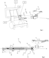
- a mining or construction vehicle 10 according to an aspect of the invention is shown.
- the mining or construction vehicle 10 comprises an extendable boom 12 with a first and a second telescopic section 13 and 14, respectively, extending in a longitudinal direction D1, i.e. the axial direction, of the extendable boom 12.
- the first telescopic section 13 is arranged to be connected to the mining or construction vehicle 10 and a hydraulic device (not shown) is arranged on a mounting device 11 in connection to a free end 18 of the second telescopic section 14 of the extendable boom 12.
- the vehicle is a drill rig and the hydraulic device is a hydraulic rock drilling machine, typically comprising a percussive drill hammer.
- the mounting device 11 is arranged in connection to the free end 18 of the second telescopic section 14, but the fact that it is arranged in connection to a free end 18 of the second telescopic section 14 of the extendable boom 12 should be construed as it may be arranged at a distance from the extendable boom 12, e.g. connected via a further boom or the like.
- the extendable boom 12 may comprise more than two telescopic sections, wherein additional sections may be telescopically arranged between the first and second telescopic sections 13 and 14.
- the mounting device 11 arranged to carry the hydraulic device is arranged on a pivot arm at the free end 18 of the extendable boom 12.
- the mounting device 11 may e.g. be comprised of a mounting plate, a bracket, a holder or a set of mounting holes for attachment of a hydraulic device.
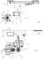
- the extendable boom 12 is shown in a longitudinal section in fig. 2 .
- a hydraulic cylinder 19 is arranged in connection to the extendable boom 12 to govern the extension of said extendable boom 12.
- the hydraulic cylinder 19 is arranged inside the extendable boom 12.
- the extendable boom 12 is connected to the hydraulic device arranged on the mounting device 11 via a first and a second rotation device 15 and 16, respectively.
- the first rotation device 15 is arranged at a free end 18 of the extendable boom 12 to provide a rotation R1 around a first axis A1 that is substantially parallel to the longitudinal direction D1.
- the first axis A1 coincides with and is parallel to the longitudinal direction D1 of the extendable boom 12.
- the second rotation device 16 is arranged to provide a rotation R2 around a second axis A2 that is arranged at an angle with respect to the first axis A1.
- the rotation devices are interconnected by an angle unit 32, which comprises an intermediate part 37 with a first attachment device for attachment to a rotating part of the first rotation device 15, and a second attachment device for attachment to the second rotation device 16.
- the first and second attachment devices of the intermediate part 37 are arranged at an angle with respect to each other, said angle corresponding to the angle between the first rotation axis A1 and the second rotation axis A2.
- This angle is preferably about 90° and preferably larger than 60° or more preferably larger than 80°, and preferably smaller than 120°, more preferably smaller than 110°.
- the hydraulic device arranged on the mounting device 11 needs pressurised hydraulic fluid to function.
- the pressurised hydraulic fluid is provided from a pressure source 30 on the mining or construction vehicle 10.
- the hydraulic conduits 17 for supply of hydraulic fluid to the hydraulic device are arranged through the extendable boom 12. Specifically, the hydraulic conduits 17 are arranged inside the hydraulic cylinder 19. Further, additional conduits, such as conduits for providing flushing medium and pressurised air to the hydraulic device are provided. In a preferred embodiment, such additional conduits are also arranged inside the extendable boom 12.
- the hydraulic cylinder 19 may be arranged outside of the extendable boom 12.
- the hydraulic conduits 17 may however still be arranged inside the extendable boom 12.
- both the hydraulic cylinder 19 and the hydraulic conduits 17 may be arranged inside the extendable boom 12, side by side, i.e. with the hydraulic conduits inside the extendable boom 12 but outside the hydraulic cylinder 19.
- the hydraulic conduits 17, which are arranged for supply of hydraulic fluid to the hydraulic device arranged on the mounting device 11, extend through both the first and second rotation devices 15 and 16.
- the hydraulic conduits 17 are arranged through only one of the rotation devices, either the first or second rotation device 15 or 16. In such a case, the hydraulic conduits 17 are arranged past the other rotation device on the outside of it.
- the hydraulic conduits 17 are arranged through the free end 18 of the extendable boom 12, i.e. through the free end of the second telescopic section 14.
- the hydraulic conduits 17 extend substantially in parallel with the extendable boom 12 in the longitudinal direction D1 out from the free end 18 of the extendable boom 12.
- the hydraulic conduits 17 are arranged to extend through an end part of the hydraulic cylinder 19 and further out through the free end 18 of the extendable boom 12.
- the conduits 17 for supply to the hydraulic device are telescopically extendable, which will be more closely described below.
- the first rotation device 15 is arranged at a free end 18 of the extendable boom 12, wherein the first rotation device 15 has a through hole and wherein the hydraulic conduits 17 are arranged through said through hole of the first rotation device 15.
- the second rotation device 16 also comprises a through hole, wherein the hydraulic conduits 17 are arranged through said through hole of the second rotation device 16.
- the rotation devices are hydraulically driven worm gear motors with an external drive allowing the hydraulic conduits 17 to pass through the centre of the first or second rotation device, or both.
- a skilled person will know that are other ways of providing a rotational motor with a central through hole allowing conduits to pass centrally, an example being a hydraulic motor with a centrally located swivel arrangement.
- each conduit is swiveled twice, on both sides of an angle of about 90°.
- a first set of swivels 23 are arranged to allow the conduits extending through the first rotation device to rotate around an axis that is substantially parallel to the first axis or rotation A1 of the first rotation device 15.
- a second set of swivels 24 are arranged to allow the conduits 17 to rotate around an axis that is substantially parallel to the second axis of rotation A2 of the second rotation device 16.
- Each swivel may e.g. be a rotatable hose coupling.
- the swivel arrangement may comprise one or two multi-swivels providing a swivel connection for a plurality of hydraulic conduits.
- such a multi-swivel may be a part of a rotation device 15 or 16, and provided centrally inside said rotation device.
- the conduits may be connected axially to the multi-swivel of the first rotation device 15 from the inside of the extendable boom 12.
- the swiveled conduits may extend either axially or radially out from the free end of the extendable boom.
- a similar arrangement may be arranged at the second rotation device 16, with conduits arriving either radially or axially with respect to the second axis of rotation A2 from the first rotation device.
- the swiveled fluid conduits preferably extend axially out from the second rotation device 16 towards the hydraulic device arranged on the mounting device 11. If the conduits are arranged radially from the first rotation device 15, they will extend axially out from the second rotation device 16, whereas they may extend either radially or axially to the hydraulic device if the conduits enter axially from the first rotation device 15.
- hydraulic connectors 27, e.g. individual connectors, are provided, which hydraulic connectors in conjunction with the set of swivels 23 and 24 form an angle that correspond to the angle between the first and second axis of rotation A1 and A2, respectively. In the shown embodiment, this angle is about 90°.
- the angle is preferably larger than 60° or more preferably larger than 80°, and smaller than 120°, more preferably smaller than 110° or even 100°.
- only one set of swivels, or one multi-swivel is arranged for any which one of the rotation devices, wherein the conduits are arranged to flex along with the rotation of the other rotation device.
- a valve unit 25 is arranged at the mounting device 11, or in connection to the second rotation device 16.
- the valve unit 25 is arranged to provide the different functions of the hydraulic device with a hydraulic pressure.
- the valve unit 25 allows the number of conduits that need to be arranged to the hydraulic device to be minimised.
- At least one of the hydraulic conduits 17 is a pressure line from a pressure source arranged on the mining or construction vehicle.
- a return line leading to tank needs to be arranged.
- a diverter valve 26, separate from the valve unit 25, may be arranged to provide the rotation motors 15 and 16 with pressurised hydraulic fluid.
- the hydraulic device is a rock drilling machine.
- a rock drilling machine normally needs three hydraulic pressurised inputs, a first input for the percussion of the drill string, a second input for the rotation of the drill string and a third input for the forward feed of the drilling machine in the drilling direction.
- these three inputs may be provided from one combined hydraulic supply conduit.
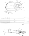
- Fig. 5 shows a partly cut view of an exemplary embodiment of hydraulic conduits 17A-D arranged inside a hydraulic cylinder 19 that is arranged to govern the extension of the extendable boom 12.
- the hydraulic conduits 17 are comprised of four different conduits, a first conduit 17A to a percussive unit of the drilling machine, a second conduit 17B to a rotation motor of the drilling machine, a third conduit 17C to a feed device for feeding the drilling machine back and forth, and a fourth conduit 17D for a return flow to tank.
- FIG. 5 Also shown in Fig. 5 are the hydraulic connections 34 and 35 providing the hydraulic cylinder 19 with hydraulic fluid, and a conduit 33 to the rod side of the hydraulic cylinder 19.
- Fig. 6 is a cut view along the longitudinal direction D1 of the hydraulic cylinder 19. From this view it is apparent that each hydraulic conduit 17A-D is telescopic, comprising two tubular sections each, whereof a smaller tubular section is arranged to slide within a relatively larger tubular section.
- the individual hydraulic conduits may also comprise three or more telescopic sections. Specifically, the embodiment with three telescopic sections may be made neutral with respect to pressure and volume, such that a conduit may expand lengthwise without affecting its interior volume or the pressure inside it.
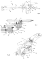
- the hydraulic conduits 17 extend through the piston end part 36, substantially parallel with the longitudinal direction D1 of the extendable boom 12.
- Fig. 7 it is shown how the hydraulic conduits 17 extend through the piston end part 36 from where they will continue through the free end of the extendable boom 12.
- a sensor 21 is arranged to monitor the extension of the extendable boom 12 in the longitudinal direction D1.
- the sensor 21 may be arranged on anyone of the moving parts, i.e. on the extendable boom 12 or on the hydraulic cylinder 19.
- a control unit 22 is arranged to control operation of the hydraulic device and to monitor other operations of the mining or construction vehicle 10, see fig. 1 .
- the control unit 22 is inter alia arranged to monitor commands issued by an operator, such as commands relating to the extension of the extendable boom 12 in the longitudinal direction D1.
- the control unit 22 may physically be arranged anywhere, e.g. on the mining or construction vehicle 10, on the extendable boom 12, or at a distant location in communication with a communication unit at the mining or construction vehicle 10.
- the control unit 22 is also arranged to compare the commanded extension of the extendable boom 12 with the actual extension as monitored by the sensor 21. Such a comparison may be made as a method of detecting a leak in anyone of the hydraulic conduits arranged inside the hydraulic cylinder 19. If the actual extension as monitored by the sensor 21 is greater than the commanded extension of the extendable boom 12 this may be due to a leak in one of the pressurised hydraulic conduits 17A-C. Namely, the leaking pressurised hydraulic fluid from the pressurised hydraulic conduits 17A-C will leak into the hydraulic cylinder, mixing with the hydraulic fluid of the hydraulic cylinder and causing the piston of the hydraulic cylinder to extend so as to extend the extendable boom 12. Alternatively, if a low-pressure conduit, such as the return conduit 17D, is broken fluid may leak from the hydraulic cylinder and into said return conduit 17D such that an undesired retraction of the extendable boom may be noted.
- a low-pressure conduit such as the return conduit 17D
- an alert signal may be issued, or under certain conditions the system may be shut down and/or the operation interrupted. The operation may be resumed only after the problem has been identified and attended to.
- the distinction between issuing a warning signal and system shut down may be decided by the magnitude of the discrepancy, such that when a discrepancy exceeding a first threshold is noted a warning signal is issued, and when a discrepancy exceeding a second threshold, which is greater than the first threshold, is noted the system is shut down and/or the operation interrupted.
- the control unit 22 may be arranged to govern a compensation of the discrepancy, e.g.
- the arrangement of detecting leaks inside a hydraulic cylinder may be used irrespective of where the hydraulic cylinder is arranged. It is however specifically useful in applications where a hydraulic device is arranged on an extendable boom such that hydraulic conduits will need to be arranged along or inside the extendable boom.
- the control unit 22 may also be arranged to control the operation of the hydraulic device in dependence of the extension of the extendable boom 12.
- a hydraulic device includes a hydraulic motor that works in a specific frequency.
- the hydraulic device is a drilling machine it comprises a percussion hammer producing strong hydraulic pulses by means of which a drill string is intermittently pushed further into the material being drilled to form a bore hole into/through the same.
- These pulses are produced with a specific frequency, which is adaptable as one of several drilling parameters in order to optimize a drilling operation.
- the frequency may e.g. be adapted as a function of the properties of the material in which the drilling is performed.
- a problem that needs to be considered with extendable hydraulic conduits 17 is the vibration of the hydraulic device, which may cause resonance problems in the hydraulic conduits. Resonance may lead to detrimental vibrations causing instability, fatigue and, as a worst case, total break-down of the system.
- Each conduit may be regarded as a trombone pipe with a specific resonance frequency, which is a direct function of the length of said hydraulic conduit. If this resonance frequency coincides with a frequency of a vibrating or oscillating hydraulic device, such as a rotating drilling machine or a percussion hammer, the conduit may start to self-oscillate, thereby risking serious negative consequences. Especially, the frequency of a percussive hammer of a hydraulic percussion rock drill needs to be considered.
- the percussions of the percussive creates pulsations that may propagate backwards through the hydraulic medium in the first conduit 17A to a percussive unit of the drilling machine. During a continuous drilling operation, these pulsations will have a frequency corresponding to the frequency of the percussive hammer.
- the control unit 22 may be arranged to operate a hydraulic device such as a percussive drilling machine so as to avoid operating frequencies that has been identified to be prone to produce resonances and/or self-oscillation. Hence, drilling frequencies that may be prone to produce resonances are identified for specific extensions of the extendable boom 12. Subsequently, during a drilling operation, the control unit 22 is arranged to compare a current extension of the extendable boom 12 with a current drilling frequency of the drilling machine. If it is noted that a commanded drilling frequency may be prone to produce a resonance at the current extension of the extendable boom 12, the control unit will issue a warning or a command to avoid said commanded drilling frequency. The drilling machine may then be set to operate at a different drilling frequency that has not been identified as prone to produce a resonance at the current extension of the extendable boom 12, or the extension of the extendable boom 12 may be altered.
- a hydraulic device such as a percussive drilling machine so as to avoid operating frequencies that has been identified to be prone to
- the set-up of the drilling or construction vehicle preferably set up so as to avoid an extension of the extendable boom corresponding to a length of a hydraulic conduit that may risk to interfere with the drilling frequency range to be used.
- a hydraulic device arranged in connection to an extendable boom, and specifically, a drilling end of a drilling machine at one specific location by adapting other parameters than the extension of the extendable boom, such as e.g. the position of the drilling or construction vehicle, the angles of the extendable boom with respect to both the vehicle and/or the feed beam.
- an attenuator may be arranged to attenuate the vibration of the hydraulic conduits.
- the fact that the hydraulic conduits 17 are arranged inside the hydraulic cylinder 19, embedded in a hydraulic fluid, will dampen their possibilities to oscillate and hence also restrict the self-oscillation of the hydraulic conduits 17.
- This is particularly useful for the conduit 17A to the percussive unit of the drilling machine, and in one embodiment, said embodiment not forming part of the invention, only the conduit 17A to the percussive unit of the drilling machine is embedded inside the hydraulic cylinder 19. Nevertheless, it may still be of importance to dampen the possibility of self-oscillation of the hydraulic conduits 17 by avoiding specific drilling frequencies in combination with specific extensions of the extendable boom 12.
- a hydraulic feed system 31 comprising a supply tank and a pump may be arranged in connection to the hydraulic cylinder 19 to compensate a fluid volume in at least one of the hydraulic conduits 17 for supply to a drilling machine.
- the control unit 22 may be part of the hydraulic feed system and is arranged to control a compensation by supplying a hydraulic flow to the hydraulic conduit corresponding to the increased volume of said hydraulic conduit.
- the control unit 22 may be configured to control a compensation by allowing a hydraulic flow corresponding to the decreased volume of said hydraulic conduit to escape from the hydraulic conduit.
- a consumer may be connected to the return line to make sure that too much hydraulic fluid is not drawn from the conduits.
Landscapes
- Engineering & Computer Science (AREA)
- Geology (AREA)
- Life Sciences & Earth Sciences (AREA)
- Mining & Mineral Resources (AREA)
- Environmental & Geological Engineering (AREA)
- Fluid Mechanics (AREA)
- Physics & Mathematics (AREA)
- General Life Sciences & Earth Sciences (AREA)
- Geochemistry & Mineralogy (AREA)
- Mechanical Engineering (AREA)
- Earth Drilling (AREA)
- Jib Cranes (AREA)
- Forklifts And Lifting Vehicles (AREA)
Claims (10)
- Ausziehbarer Ausleger (12) einer Bohranlage (10),wobei der ausziehbare Ausleger (12) mindestens einen ersten und einen zweiten Teleskopabschnitt (13, 14) umfasst, die sich in einer Längsrichtung (D1) erstrecken, wobei der erste Teleskopabschnitt (13) so angeordnet ist, dass er mit der Bohranlage (10) verbunden wird, der zweite Teleskopabschnitt (14) ein freies Ende (18) umfasst, wobei eine Befestigungsvorrichtung (11) in Verbindung mit dem freien Ende (18) des zweiten Teleskopabschnitts (14) in einem Abstand von dem ausziehbaren Ausleger (12) angeordnet ist unddie Befestigungsvorrichtung (11) so angeordnet ist, dass sie eine hydraulische Schlagbohrmaschine trägt, die so angeordnet ist, dass sie mit der Befestigungsvorrichtung (11) verbunden wird,wobei ein Hydraulikzylinder (19) in Verbindung mit dem ausziehbaren Ausleger (12) angeordnet ist, um das Ausziehen des ausziehbaren Auslegers (12) zu steuern, wobei der Hydraulikzylinder (19) innerhalb des ausziehbaren Auslegers (12) angeordnet ist,wobei innerhalb des Hydraulikzylinders (19) mindestens eine Hydraulikleitung (17) zur Zuführung von Hydraulikflüssigkeit zu der mit der Befestigungsvorrichtung (11) verbundenen hydraulischen Schlagbohrmaschine angeordnet ist, undwobei die mindestens eine Hydraulikleitung (17) durch das freie Ende (18) des zweiten Teleskopabschnitts (14) angeordnet ist.
- Ausziehbarer Ausleger (12) nach Anspruch 1, wobei sich die mindestens eine Hydraulikleitung (17) im Wesentlichen parallel zum ausziehbaren Ausleger (12) in der Längsrichtung (D1) von dem freien Ende (18) des zweiten Teleskopabschnitts (14) des ausziehbaren Auslegers (12) aus erstreckt.
- Ausziehbarer Ausleger (12) nach Anspruch 1 oder 2, wobei die mindestens eine Hydraulikleitung (17) zur Zuführung zu der hydraulischen Schlagbohrmaschine teleskopartig ausziehbar ist.
- Ausziehbarer Ausleger (12) nach einem der vorstehenden Ansprüche, wobei die hydraulische Schlagbohrmaschine eine Schlageinheit umfasst und wobei die mindestens eine Hydraulikleitung (17) aus einer ersten Leitung (17A) besteht, die zur Zuführung von Hydraulikflüssigkeit zu der Schlageinheit angeordnet ist.
- Ausziehbarer Ausleger (12) nach einem der Ansprüche 1-3, wobei die mindestens eine Hydraulikleitung (17) vier verschiedene Hydraulikleitungen umfasst, eine erste Leitung (17A) zu einer Schlageinheit der Bohrmaschine, eine zweite Leitung (17B) zu einem Rotationsmotor der Bohrmaschine, eine dritte Leitung (17C) zu einer Vorschubvorrichtung für den Vorwärts- und Rückwärtsvorschub der Bohrmaschine und eine vierte Leitung (17D) für einen Rückfluss zum Tank.
- Ausziehbarer Ausleger (12) nach einem der vorstehenden Ansprüche, weiter umfassend
einen Sensor (21), der so angeordnet ist, dass er das Ausziehen des ausziehbaren Auslegers (12) überwacht, und eine Steuereinheit (22), die so angeordnet ist, dass sie das überwachte Ausziehen mit dem befohlenen Ausziehen vergleicht. - Ausziehbarer Ausleger (12) nach Anspruch 6, wobei ein Warnsignal ausgegeben wird, wenn die Steuereinheit eine Abweichung zwischen dem überwachten Ausziehen und dem befohlenen Ausziehen des Hydraulikzylinders (19) erfasst.
- Ausziehbarer Ausleger (12) nach Anspruch 6 oder 7,wobei ein Vorschubsystem (31) zum Ausgleich eines Fluidvolumens in der mindestens einen Hydraulikleitung (17) zur Zuführung von Hydraulikflüssigkeit zu der hydraulischen Schlagbohrmaschine angeordnet ist, undwobei die Steuereinheit (22) so angeordnet ist, dass sie eine Zuführung von Hydraulikflüssigkeit zu der mindestens einen Hydraulikleitung (17) entsprechend dem vergrößerten Volumen der mindestens einen Hydraulikleitung (17) steuert, und,wenn die mindestens eine Hydraulikleitung (17) verdichtet wird, die Steuereinheit (22) so angeordnet ist, dass sie eine Abgabe von Hydraulikflüssigkeit aus der mindestens einen Hydraulikleitung (17) entsprechend dem verringerten Volumen der mindestens einen Hydraulikleitung (17) aufgrund der Tatsache, dass sie verdichtet wird, steuert.
- Ausziehbarer Ausleger (12) nach einem der Ansprüche 6-8,wobei die hydraulische Schlagbohrmaschine eine Gesteinsbohrmaschine ist, die mit verschiedenen Schlagfrequenzen arbeitet, undwobei die Steuereinheit (22) so angeordnet ist, dass sie den Betrieb der hydraulischen Schlagbohrmaschine steuert, sodass Schlagfrequenzen vermieden werden, von denen festgestellt wurde, dass sie dazu neigen, Resonanzen in der mindestens einen Hydraulikleitung (17) zu erzeugen, und/oder dass sie das Ausziehen des ausziehbaren Auslegers (12) steuert, sodass eine Länge der mindestens einen Hydraulikleitung (17), die eine gewünschte Schlagfrequenz stören kann, vermieden wird.
- Bohranlage (10), umfassend den ausziehbaren Ausleger (12) nach einem der vorstehenden Ansprüche.
Applications Claiming Priority (2)
| Application Number | Priority Date | Filing Date | Title |
|---|---|---|---|
| SE1751090A SE542480C2 (en) | 2017-09-08 | 2017-09-08 | Mining or construction vehicle enclosing a conduit arrangement |
| PCT/EP2018/065311 WO2019048094A1 (en) | 2017-09-08 | 2018-06-11 | MINING OR CONSTRUCTION VEHICLE AND HYDRAULIC CYLINDER CONDUIT COMPRISING A DUCT ARRANGEMENT |
Publications (3)
| Publication Number | Publication Date |
|---|---|
| EP3679224A1 EP3679224A1 (de) | 2020-07-15 |
| EP3679224C0 EP3679224C0 (de) | 2024-02-14 |
| EP3679224B1 true EP3679224B1 (de) | 2024-02-14 |
Family
ID=62916607
Family Applications (1)
| Application Number | Title | Priority Date | Filing Date |
|---|---|---|---|
| EP18740734.1A Active EP3679224B1 (de) | 2017-09-08 | 2018-06-11 | Ausziehbarer ausleger einer bohranlage und bohranlage mit diesem ausziehbaren ausleger |
Country Status (10)
| Country | Link |
|---|---|
| US (1) | US11661797B2 (de) |
| EP (1) | EP3679224B1 (de) |
| CN (1) | CN111051646B (de) |
| AU (1) | AU2018328654B2 (de) |
| CA (1) | CA3071343A1 (de) |
| PE (1) | PE20200672A1 (de) |
| RU (1) | RU2020113007A (de) |
| SE (1) | SE542480C2 (de) |
| WO (1) | WO2019048094A1 (de) |
| ZA (1) | ZA202000607B (de) |
Families Citing this family (5)
| Publication number | Priority date | Publication date | Assignee | Title |
|---|---|---|---|---|
| SE541217C2 (en) | 2017-09-08 | 2019-05-07 | Epiroc Rock Drills Ab | Mining or construction vehicle |
| PL3710394T3 (pl) | 2017-12-13 | 2024-06-10 | Joy Global Underground Mining Llc | Podpora narzędzia wiertniczego i wkręcającego |
| FI4008880T3 (fi) * | 2020-12-01 | 2023-12-18 | Sandvik Mining & Construction Oy | Pyörityslaite kaivosajoneuvon puomia varten ja kaivosajoneuvo |
| AU2022228085A1 (en) * | 2021-09-07 | 2023-03-23 | Joy Global Underground Mining Llc | Support for drilling and bolting tool |
| WO2026011210A1 (en) * | 2024-07-09 | 2026-01-15 | Technological Resources Pty Ltd | A safety system for a drilling machine |
Citations (2)
| Publication number | Priority date | Publication date | Assignee | Title |
|---|---|---|---|---|
| US3207044A (en) * | 1963-05-20 | 1965-09-21 | Thomas R Hall | Feeder tube cylinder |
| US3664527A (en) * | 1969-11-10 | 1972-05-23 | Clark Equipment Co | Material handling apparatus |
Family Cites Families (76)
| Publication number | Priority date | Publication date | Assignee | Title |
|---|---|---|---|---|
| US1851940A (en) | 1929-11-13 | 1932-03-29 | Orr H Williams | Closure for conduits and the like |
| US2813692A (en) | 1954-05-28 | 1957-11-19 | Boeing Co | Sealed bulkhead installations of electric wires |
| GB908133A (en) | 1959-12-31 | 1962-10-17 | Dowty Mining Equipment Ltd | Fluid-operated telescopic devices |
| US3187916A (en) | 1962-06-06 | 1965-06-08 | Shaft Machines Ltd | Mucking machines and excavators of the telescopic boom-type |
| FR1408620A (fr) | 1964-09-23 | 1965-08-13 | Super Oil Seals & Gaskets Ltd | Raccord tournant étanche utilisable dans un système hydraulique |
| US3315821A (en) | 1966-03-15 | 1967-04-25 | Grove Mfg Co | Four-section fully hydraulically operated boom |
| GB1234981A (en) | 1967-04-07 | 1971-06-09 | Lino Arcangeli | Improvements in or relating to drilling apparatus |
| SE303115B (de) | 1967-05-24 | 1968-08-19 | Atlas Copco Ab | |
| SE321909C (de) | 1968-03-12 | 1975-01-20 | Atlas Copco Ab | |
| US3623501A (en) * | 1970-07-13 | 1971-11-30 | Chance Co Ab | Continuous hydraulic hose structure for telescopic boom assembly |
| US3696712A (en) | 1970-09-28 | 1972-10-10 | Kidde & Co Walter | Multi-section hydraulic ram |
| GB1356022A (en) * | 1971-02-10 | 1974-06-12 | Dobson Park Ind | Impact tools or apparatus |
| US3776367A (en) | 1972-06-12 | 1973-12-04 | Fulton Industries | Mobile aerial platform |
| US3840128A (en) | 1973-07-09 | 1974-10-08 | N Swoboda | Racking arm for pipe sections, drill collars, riser pipe, and the like used in well drilling operations |
| US3920084A (en) | 1973-11-21 | 1975-11-18 | Jr Wayne B Russell | Extendable and retractible material delivery devices |
| US3980142A (en) | 1975-09-10 | 1976-09-14 | Grigoriev Vladimir Konstantino | Drilling boom |
| FR2328836A1 (fr) | 1975-10-22 | 1977-05-20 | Pk Experime | Bras de forage |
| US4023836A (en) | 1975-12-15 | 1977-05-17 | The Gates Rubber Company | Split flange retainer for flanged conduits |
| CA1061827A (en) | 1977-05-20 | 1979-09-04 | George A. Grace | Rotatable pipe coupling structure |
| ZA777581B (en) * | 1977-12-21 | 1979-05-30 | L Herron | Improvements in or relating to rock drilling rigs |
| US4199299A (en) | 1978-01-09 | 1980-04-22 | Petitto Mine Equipment Repair, Inc. | Material handling apparatus for use in a mine |
| DE3003377C2 (de) | 1980-01-31 | 1983-10-06 | Gewerkschaft Eisenhuette Westfalia, 4670 Luenen | Steckkupplung für Schlauchleitungsbündel |
| DE3015809A1 (de) | 1980-04-24 | 1981-10-29 | Gewerkschaft Eisenhütte Westfalia, 4670 Lünen | Armatur fuer ein- oder mehradrige schlauch- oder kabelleitungen |
| EP0066755A1 (de) | 1981-06-10 | 1982-12-15 | Intradym Maschinen Ag | Schlauchführungseinrichtung für eine Betonspritzanlage |
| US4459898A (en) | 1981-12-09 | 1984-07-17 | Nordson Corporation | Streamlined multi-axis robot wrist assembly with partially enclosed hydraulic and electrical lines to minimize the wrist envelope |
| FR2519690A1 (fr) | 1982-01-11 | 1983-07-18 | Montabert Ets | Dispositif d'asservissement electro-hydraulique de bras-support articule pour glissiere d'appareil de foration |
| DE3204102A1 (de) | 1982-02-06 | 1983-08-11 | Gewerkschaft Eisenhütte Westfalia, 4670 Lünen | Mehradriges hydraulisches oder pneumatisches kabel mit mehrfachschlauchkupplung |
| DE3216553A1 (de) | 1982-05-04 | 1983-11-10 | Gewerkschaft Eisenhütte Westfalia, 4670 Lünen | Anschlussstueck fuer mehradrige hydraulische oder pneumatische schlauchleitungen, insbesondere fuer hydraulische ausbausysteme |
| DE3235554A1 (de) | 1982-09-25 | 1984-03-29 | Gewerkschaft Eisenhütte Westfalia, 4670 Lünen | Steckkupplung fuer mehradrige hydraulische oder pneumatische kabel |
| JPS604647U (ja) * | 1983-06-18 | 1985-01-14 | セイレイ工業株式会社 | バツクホ−における油圧シリンダの油路構造 |
| FI84642C (fi) | 1989-03-10 | 1991-12-27 | Minkkinen Risto J | Anordning foer transport av fluider. |
| SE500903C2 (sv) | 1989-12-20 | 1994-09-26 | Atlas Copco Constr & Mining | Bergborrningsrigg |
| DE4222007C2 (de) | 1992-07-04 | 2001-11-15 | Eichhorn Friedrich Prof Dr | Vorrichtung zum Reinigen von Großbehältnissen, insbesondere Hochdruckreaktoren |
| DE4318872A1 (de) | 1993-06-07 | 1994-12-08 | Moeller Hamburg Gmbh Co Kg | Doppelrohr für eine pneumatische Förderung |
| US5458375A (en) | 1994-04-25 | 1995-10-17 | The Anspach Effort, Inc. | Rotary connector for fluid conduits |
| JP2951205B2 (ja) | 1994-06-17 | 1999-09-20 | 古河機械金属株式会社 | 多段伸縮ブームのホース保持構造 |
| FI96054C (fi) | 1994-08-30 | 1996-04-25 | Tamrock Oy | Sovitelma kallionporauslaitteen puomissa |
| US5558118A (en) | 1995-05-30 | 1996-09-24 | Mooring; Jonathon E. | System for remotely controlling the unreeling and take-up of a hose on a reel |
| JPH1052390A (ja) | 1996-08-12 | 1998-02-24 | Kyowa Kikai Seisakusho:Kk | 伸縮式配管 |
| DE19641789C1 (de) | 1996-10-10 | 1998-07-16 | Korthaus Ernst | Betonverteilersystem für Transportbeton |
| GB2321634A (en) | 1997-01-29 | 1998-08-05 | Weatherford Lamb | Tong positioning apparatus |
| DE29718478U1 (de) | 1997-10-17 | 1998-02-19 | Ec Engineering + Consulting Spezialmaschinen Gmbh, 89079 Ulm | Plungerzylinder als Hydraulikölzuführung |
| US5954143A (en) * | 1998-02-21 | 1999-09-21 | Mccabe; Howard Wendell | Remote controlled all-terrain drill unit |
| KR100365471B1 (ko) | 2000-02-19 | 2002-12-31 | 곽양진 | 다굴절크레인의 유압 전달장치에 의한 붐 인출장치 |
| US6435235B1 (en) | 2000-10-24 | 2002-08-20 | Caterpillar Inc. | Mounting for tree harvester head |
| LV12759B (lv) | 2001-06-01 | 2002-02-20 | Baltrotors, Sia | Grozāma uzmava |
| SE520498E8 (sv) | 2001-11-26 | 2015-10-20 | Komatsu Forest Ab | Anordning för upphängning av ett vridbart arbetsredskap |
| JP2004156299A (ja) | 2002-11-06 | 2004-06-03 | Hitachi Constr Mach Co Ltd | 建設機械の作業装置 |
| JP2005201323A (ja) | 2004-01-14 | 2005-07-28 | Mitsubishi Heavy Ind Ltd | 脈動低減装置又は脈動低減油圧装置 |
| US20050258295A1 (en) | 2004-05-24 | 2005-11-24 | Alonzo Wireman | Enclosed hose management system for sliding boom delimber |
| WO2006056849A2 (en) | 2004-11-29 | 2006-06-01 | Francois Maree Vorster | A pneumatic materials handling unit |
| SE528389C2 (sv) | 2005-03-11 | 2006-10-31 | Atlas Copco Rock Drills Ab | Vridanordning för en bom till en gruv- eller entreprenadrigg jämte rigg |
| JP4687172B2 (ja) | 2005-03-18 | 2011-05-25 | コベルコクレーン株式会社 | 伸縮ブーム |
| ATE393755T1 (de) | 2005-04-01 | 2008-05-15 | Cargotec Patenter Ab | Mehrstufiger teleskopausleger. |
| SE535073C2 (sv) | 2005-11-23 | 2012-04-03 | Motrac Ab | Teleskoparm och metod vid ett kranarrangemang |
| CN201071851Y (zh) | 2006-12-28 | 2008-06-11 | 长沙中联重工科技发展股份有限公司 | 多通道液压油缸 |
| KR20090059361A (ko) | 2007-12-06 | 2009-06-11 | 전진씨에스엠 주식회사 | 굴절사다리 소방차에 내장된 유압호스와 전원케이블설치구조 |
| FR2930004B1 (fr) | 2008-04-10 | 2013-02-08 | Commissariat Energie Atomique | Verin hydraulique et structure d'actionnement d'un bras manipulateur mettant en oeuvre au moins un tel verin |
| ES2341746B1 (es) | 2008-07-30 | 2011-05-17 | Bombas Boyser, S.L. | Amortiguador de pulsaciones para instalaciones de fluidos mediante tubo elastomerico multiple. |
| US7942208B2 (en) * | 2008-11-06 | 2011-05-17 | Purdue Research Foundation | System and method for blade level control of earthmoving machines |
| TR200902393A2 (tr) | 2009-03-27 | 2009-09-23 | Hi̇drokon Konya Hi̇droli̇k Maki̇na Sanayi̇ Ve Ti̇caret Li̇mi̇ted Şi̇rketi̇ | Katlanir bomlu vi̇nçlerde sirali bom uzatma ve geri̇ çekme si̇li̇ndi̇r si̇stemi̇nde yeni̇li̇k |
| FI121893B (fi) | 2009-04-20 | 2011-05-31 | Unisto Oy | Työkalun teleskooppisesti pitenevä varsi |
| GB2470609B (en) | 2009-05-30 | 2013-10-09 | Aker Subsea Ltd | Subsea hydraulic coupler |
| SE535386C2 (sv) | 2010-09-02 | 2012-07-17 | Tam Craft Ab | Teleskoperande cylinderanordning och fordon innefattande ett flertal sådana teleskoperande cylinderanordningar |
| DE102011115634B4 (de) | 2011-03-25 | 2021-12-30 | Tadano Demag Gmbh | Teleskopausleger |
| CN103958786A (zh) | 2011-11-30 | 2014-07-30 | 沃尔沃建造设备有限公司 | 用于动臂回转式挖掘机的液压管路固定装置 |
| US9050999B2 (en) * | 2013-01-25 | 2015-06-09 | Caterpillar Inc | System with smart steering force feedback |
| SE1300134A1 (sv) | 2013-02-20 | 2014-08-19 | Cranab Ab | Kranarm som bär en rotator |
| WO2014206471A1 (en) | 2013-06-27 | 2014-12-31 | Sandvik Mining And Construction Oy | Arrangement for controlling percussive drilling process |
| CN103470183B (zh) | 2013-08-26 | 2015-10-28 | 浙江海聚科技有限公司 | 利用钻机设备推进梁和支撑箱结构布置液压回路方法 |
| EP3059382B1 (de) | 2015-02-19 | 2017-10-11 | Sandvik Mining and Construction Oy | Bergbauausleger und verfahren zur unterstützung von schläuchen |
| CN104695871A (zh) | 2015-03-13 | 2015-06-10 | 盐城恒越电气有限公司 | 一种两臂液压锚杆钻车的钻臂装置 |
| SE541052C2 (sv) | 2015-09-30 | 2019-03-19 | Epiroc Rock Drills Ab | System och förfarande för borrplansgenerering, borrigg, datorprogram samt datorprogramprodukt |
| CN205370442U (zh) | 2016-02-24 | 2016-07-06 | 王占军 | 凿岩台车 |
| US20170129088A1 (en) | 2017-01-23 | 2017-05-11 | Caterpillar Inc. | Adaptive hammer control system |
| ES2957294T3 (es) * | 2017-04-04 | 2024-01-16 | Taimi R&D Inc | Conjunto de soporte para soportar de forma giratoria conductos hidráulicos |
-
2017
- 2017-09-08 SE SE1751090A patent/SE542480C2/en unknown
-
2018
- 2018-06-11 AU AU2018328654A patent/AU2018328654B2/en active Active
- 2018-06-11 CA CA3071343A patent/CA3071343A1/en active Pending
- 2018-06-11 WO PCT/EP2018/065311 patent/WO2019048094A1/en not_active Ceased
- 2018-06-11 US US16/645,410 patent/US11661797B2/en active Active
- 2018-06-11 RU RU2020113007A patent/RU2020113007A/ru unknown
- 2018-06-11 CN CN201880055216.4A patent/CN111051646B/zh active Active
- 2018-06-11 PE PE2020000200A patent/PE20200672A1/es unknown
- 2018-06-11 EP EP18740734.1A patent/EP3679224B1/de active Active
-
2020
- 2020-01-29 ZA ZA2020/00607A patent/ZA202000607B/en unknown
Patent Citations (2)
| Publication number | Priority date | Publication date | Assignee | Title |
|---|---|---|---|---|
| US3207044A (en) * | 1963-05-20 | 1965-09-21 | Thomas R Hall | Feeder tube cylinder |
| US3664527A (en) * | 1969-11-10 | 1972-05-23 | Clark Equipment Co | Material handling apparatus |
Also Published As
| Publication number | Publication date |
|---|---|
| RU2020113007A3 (de) | 2021-10-12 |
| WO2019048094A1 (en) | 2019-03-14 |
| CA3071343A1 (en) | 2019-03-14 |
| EP3679224A1 (de) | 2020-07-15 |
| US11661797B2 (en) | 2023-05-30 |
| RU2020113007A (ru) | 2021-10-08 |
| AU2018328654B2 (en) | 2024-03-07 |
| US20200284097A1 (en) | 2020-09-10 |
| ZA202000607B (en) | 2024-05-30 |
| CN111051646A (zh) | 2020-04-21 |
| AU2018328654A1 (en) | 2020-02-13 |
| SE542480C2 (en) | 2020-05-19 |
| CN111051646B (zh) | 2022-05-13 |
| EP3679224C0 (de) | 2024-02-14 |
| SE1751090A1 (en) | 2019-03-09 |
| PE20200672A1 (es) | 2020-06-11 |
Similar Documents
| Publication | Publication Date | Title |
|---|---|---|
| AU2020250307B2 (en) | Mining or construction vehicle | |
| EP3679224B1 (de) | Ausziehbarer ausleger einer bohranlage und bohranlage mit diesem ausziehbaren ausleger | |
| US12366163B2 (en) | Support for drilling and bolting tool | |
| JP5207768B2 (ja) | アースドリル | |
| AU2021379518A9 (en) | Feeder arrangement on a drill rig, and drill rig | |
| JP3026229B2 (ja) | 延長ロツド掘穿における削岩機送給装置 | |
| EP4405558B1 (de) | Hydraulische anordnung für eine gesteinsbohrmaschine | |
| JP7794501B2 (ja) | エネルギー回収装置 | |
| CN114245837A (zh) | 液压系统、采矿机器和控制液压致动器的方法 |
Legal Events
| Date | Code | Title | Description |
|---|---|---|---|
| STAA | Information on the status of an ep patent application or granted ep patent |
Free format text: STATUS: UNKNOWN |
|
| STAA | Information on the status of an ep patent application or granted ep patent |
Free format text: STATUS: THE INTERNATIONAL PUBLICATION HAS BEEN MADE |
|
| PUAI | Public reference made under article 153(3) epc to a published international application that has entered the european phase |
Free format text: ORIGINAL CODE: 0009012 |
|
| STAA | Information on the status of an ep patent application or granted ep patent |
Free format text: STATUS: REQUEST FOR EXAMINATION WAS MADE |
|
| 17P | Request for examination filed |
Effective date: 20200204 |
|
| AK | Designated contracting states |
Kind code of ref document: A1 Designated state(s): AL AT BE BG CH CY CZ DE DK EE ES FI FR GB GR HR HU IE IS IT LI LT LU LV MC MK MT NL NO PL PT RO RS SE SI SK SM TR |
|
| AX | Request for extension of the european patent |
Extension state: BA ME |
|
| DAV | Request for validation of the european patent (deleted) | ||
| DAX | Request for extension of the european patent (deleted) | ||
| STAA | Information on the status of an ep patent application or granted ep patent |
Free format text: STATUS: EXAMINATION IS IN PROGRESS |
|
| 17Q | First examination report despatched |
Effective date: 20210209 |
|
| GRAP | Despatch of communication of intention to grant a patent |
Free format text: ORIGINAL CODE: EPIDOSNIGR1 |
|
| STAA | Information on the status of an ep patent application or granted ep patent |
Free format text: STATUS: GRANT OF PATENT IS INTENDED |
|
| INTG | Intention to grant announced |
Effective date: 20231123 |
|
| GRAS | Grant fee paid |
Free format text: ORIGINAL CODE: EPIDOSNIGR3 |
|
| GRAA | (expected) grant |
Free format text: ORIGINAL CODE: 0009210 |
|
| STAA | Information on the status of an ep patent application or granted ep patent |
Free format text: STATUS: THE PATENT HAS BEEN GRANTED |
|
| AK | Designated contracting states |
Kind code of ref document: B1 Designated state(s): AL AT BE BG CH CY CZ DE DK EE ES FI FR GB GR HR HU IE IS IT LI LT LU LV MC MK MT NL NO PL PT RO RS SE SI SK SM TR |
|
| REG | Reference to a national code |
Ref country code: GB Ref legal event code: FG4D |
|
| REG | Reference to a national code |
Ref country code: CH Ref legal event code: EP |
|
| REG | Reference to a national code |
Ref country code: DE Ref legal event code: R096 Ref document number: 602018065199 Country of ref document: DE |
|
| REG | Reference to a national code |
Ref country code: IE Ref legal event code: FG4D |
|
| U01 | Request for unitary effect filed |
Effective date: 20240219 |
|
| U07 | Unitary effect registered |
Designated state(s): AT BE BG DE DK EE FI FR IT LT LU LV MT NL PT SE SI Effective date: 20240229 |
|
| REG | Reference to a national code |
Ref country code: LT Ref legal event code: MG9D |
|
| U20 | Renewal fee for the european patent with unitary effect paid |
Year of fee payment: 7 Effective date: 20240521 |
|
| PG25 | Lapsed in a contracting state [announced via postgrant information from national office to epo] |
Ref country code: IS Free format text: LAPSE BECAUSE OF FAILURE TO SUBMIT A TRANSLATION OF THE DESCRIPTION OR TO PAY THE FEE WITHIN THE PRESCRIBED TIME-LIMIT Effective date: 20240614 |
|
| PG25 | Lapsed in a contracting state [announced via postgrant information from national office to epo] |
Ref country code: GR Free format text: LAPSE BECAUSE OF FAILURE TO SUBMIT A TRANSLATION OF THE DESCRIPTION OR TO PAY THE FEE WITHIN THE PRESCRIBED TIME-LIMIT Effective date: 20240515 |
|
| PG25 | Lapsed in a contracting state [announced via postgrant information from national office to epo] |
Ref country code: RS Free format text: LAPSE BECAUSE OF FAILURE TO SUBMIT A TRANSLATION OF THE DESCRIPTION OR TO PAY THE FEE WITHIN THE PRESCRIBED TIME-LIMIT Effective date: 20240514 Ref country code: HR Free format text: LAPSE BECAUSE OF FAILURE TO SUBMIT A TRANSLATION OF THE DESCRIPTION OR TO PAY THE FEE WITHIN THE PRESCRIBED TIME-LIMIT Effective date: 20240214 |
|
| PG25 | Lapsed in a contracting state [announced via postgrant information from national office to epo] |
Ref country code: ES Free format text: LAPSE BECAUSE OF FAILURE TO SUBMIT A TRANSLATION OF THE DESCRIPTION OR TO PAY THE FEE WITHIN THE PRESCRIBED TIME-LIMIT Effective date: 20240214 |
|
| PG25 | Lapsed in a contracting state [announced via postgrant information from national office to epo] |
Ref country code: RS Free format text: LAPSE BECAUSE OF FAILURE TO SUBMIT A TRANSLATION OF THE DESCRIPTION OR TO PAY THE FEE WITHIN THE PRESCRIBED TIME-LIMIT Effective date: 20240514 Ref country code: NO Free format text: LAPSE BECAUSE OF FAILURE TO SUBMIT A TRANSLATION OF THE DESCRIPTION OR TO PAY THE FEE WITHIN THE PRESCRIBED TIME-LIMIT Effective date: 20240514 Ref country code: IS Free format text: LAPSE BECAUSE OF FAILURE TO SUBMIT A TRANSLATION OF THE DESCRIPTION OR TO PAY THE FEE WITHIN THE PRESCRIBED TIME-LIMIT Effective date: 20240614 Ref country code: HR Free format text: LAPSE BECAUSE OF FAILURE TO SUBMIT A TRANSLATION OF THE DESCRIPTION OR TO PAY THE FEE WITHIN THE PRESCRIBED TIME-LIMIT Effective date: 20240214 Ref country code: GR Free format text: LAPSE BECAUSE OF FAILURE TO SUBMIT A TRANSLATION OF THE DESCRIPTION OR TO PAY THE FEE WITHIN THE PRESCRIBED TIME-LIMIT Effective date: 20240515 Ref country code: ES Free format text: LAPSE BECAUSE OF FAILURE TO SUBMIT A TRANSLATION OF THE DESCRIPTION OR TO PAY THE FEE WITHIN THE PRESCRIBED TIME-LIMIT Effective date: 20240214 |
|
| PG25 | Lapsed in a contracting state [announced via postgrant information from national office to epo] |
Ref country code: PL Free format text: LAPSE BECAUSE OF FAILURE TO SUBMIT A TRANSLATION OF THE DESCRIPTION OR TO PAY THE FEE WITHIN THE PRESCRIBED TIME-LIMIT Effective date: 20240214 |
|
| PG25 | Lapsed in a contracting state [announced via postgrant information from national office to epo] |
Ref country code: PL Free format text: LAPSE BECAUSE OF FAILURE TO SUBMIT A TRANSLATION OF THE DESCRIPTION OR TO PAY THE FEE WITHIN THE PRESCRIBED TIME-LIMIT Effective date: 20240214 |
|
| PG25 | Lapsed in a contracting state [announced via postgrant information from national office to epo] |
Ref country code: SM Free format text: LAPSE BECAUSE OF FAILURE TO SUBMIT A TRANSLATION OF THE DESCRIPTION OR TO PAY THE FEE WITHIN THE PRESCRIBED TIME-LIMIT Effective date: 20240214 |
|
| PG25 | Lapsed in a contracting state [announced via postgrant information from national office to epo] |
Ref country code: CZ Free format text: LAPSE BECAUSE OF FAILURE TO SUBMIT A TRANSLATION OF THE DESCRIPTION OR TO PAY THE FEE WITHIN THE PRESCRIBED TIME-LIMIT Effective date: 20240214 |
|
| PG25 | Lapsed in a contracting state [announced via postgrant information from national office to epo] |
Ref country code: SK Free format text: LAPSE BECAUSE OF FAILURE TO SUBMIT A TRANSLATION OF THE DESCRIPTION OR TO PAY THE FEE WITHIN THE PRESCRIBED TIME-LIMIT Effective date: 20240214 |
|
| PG25 | Lapsed in a contracting state [announced via postgrant information from national office to epo] |
Ref country code: SM Free format text: LAPSE BECAUSE OF FAILURE TO SUBMIT A TRANSLATION OF THE DESCRIPTION OR TO PAY THE FEE WITHIN THE PRESCRIBED TIME-LIMIT Effective date: 20240214 Ref country code: SK Free format text: LAPSE BECAUSE OF FAILURE TO SUBMIT A TRANSLATION OF THE DESCRIPTION OR TO PAY THE FEE WITHIN THE PRESCRIBED TIME-LIMIT Effective date: 20240214 Ref country code: RO Free format text: LAPSE BECAUSE OF FAILURE TO SUBMIT A TRANSLATION OF THE DESCRIPTION OR TO PAY THE FEE WITHIN THE PRESCRIBED TIME-LIMIT Effective date: 20240214 Ref country code: CZ Free format text: LAPSE BECAUSE OF FAILURE TO SUBMIT A TRANSLATION OF THE DESCRIPTION OR TO PAY THE FEE WITHIN THE PRESCRIBED TIME-LIMIT Effective date: 20240214 |
|
| REG | Reference to a national code |
Ref country code: DE Ref legal event code: R097 Ref document number: 602018065199 Country of ref document: DE |
|
| PLBE | No opposition filed within time limit |
Free format text: ORIGINAL CODE: 0009261 |
|
| STAA | Information on the status of an ep patent application or granted ep patent |
Free format text: STATUS: NO OPPOSITION FILED WITHIN TIME LIMIT |
|
| 26N | No opposition filed |
Effective date: 20241115 |
|
| PG25 | Lapsed in a contracting state [announced via postgrant information from national office to epo] |
Ref country code: MC Free format text: LAPSE BECAUSE OF FAILURE TO SUBMIT A TRANSLATION OF THE DESCRIPTION OR TO PAY THE FEE WITHIN THE PRESCRIBED TIME-LIMIT Effective date: 20240214 |
|
| REG | Reference to a national code |
Ref country code: CH Ref legal event code: PL |
|
| GBPC | Gb: european patent ceased through non-payment of renewal fee |
Effective date: 20240611 |
|
| PG25 | Lapsed in a contracting state [announced via postgrant information from national office to epo] |
Ref country code: IE Free format text: LAPSE BECAUSE OF NON-PAYMENT OF DUE FEES Effective date: 20240611 |
|
| PG25 | Lapsed in a contracting state [announced via postgrant information from national office to epo] |
Ref country code: CH Free format text: LAPSE BECAUSE OF NON-PAYMENT OF DUE FEES Effective date: 20240630 |
|
| PG25 | Lapsed in a contracting state [announced via postgrant information from national office to epo] |
Ref country code: GB Free format text: LAPSE BECAUSE OF NON-PAYMENT OF DUE FEES Effective date: 20240611 |
|
| U20 | Renewal fee for the european patent with unitary effect paid |
Year of fee payment: 8 Effective date: 20250520 |
|
| PG25 | Lapsed in a contracting state [announced via postgrant information from national office to epo] |
Ref country code: CY Free format text: LAPSE BECAUSE OF FAILURE TO SUBMIT A TRANSLATION OF THE DESCRIPTION OR TO PAY THE FEE WITHIN THE PRESCRIBED TIME-LIMIT; INVALID AB INITIO Effective date: 20180611 |
|
| PG25 | Lapsed in a contracting state [announced via postgrant information from national office to epo] |
Ref country code: HU Free format text: LAPSE BECAUSE OF FAILURE TO SUBMIT A TRANSLATION OF THE DESCRIPTION OR TO PAY THE FEE WITHIN THE PRESCRIBED TIME-LIMIT; INVALID AB INITIO Effective date: 20180611 |