EP3679227B1 - Totzweig für die teilchenabscheidung für den kontinuierlichen online-betrieb - Google Patents
Totzweig für die teilchenabscheidung für den kontinuierlichen online-betrieb Download PDFInfo
- Publication number
- EP3679227B1 EP3679227B1 EP18773917.2A EP18773917A EP3679227B1 EP 3679227 B1 EP3679227 B1 EP 3679227B1 EP 18773917 A EP18773917 A EP 18773917A EP 3679227 B1 EP3679227 B1 EP 3679227B1
- Authority
- EP
- European Patent Office
- Prior art keywords
- debris
- dead leg
- cooling flow
- extractor
- cooling
- Prior art date
- Legal status (The legal status is an assumption and is not a legal conclusion. Google has not performed a legal analysis and makes no representation as to the accuracy of the status listed.)
- Active
Links
Images

Classifications
-
- F—MECHANICAL ENGINEERING; LIGHTING; HEATING; WEAPONS; BLASTING
- F01—MACHINES OR ENGINES IN GENERAL; ENGINE PLANTS IN GENERAL; STEAM ENGINES
- F01D—NON-POSITIVE DISPLACEMENT MACHINES OR ENGINES, e.g. STEAM TURBINES
- F01D25/00—Component parts, details, or accessories, not provided for in, or of interest apart from, other groups
- F01D25/002—Cleaning of turbomachines
-
- F—MECHANICAL ENGINEERING; LIGHTING; HEATING; WEAPONS; BLASTING
- F01—MACHINES OR ENGINES IN GENERAL; ENGINE PLANTS IN GENERAL; STEAM ENGINES
- F01D—NON-POSITIVE DISPLACEMENT MACHINES OR ENGINES, e.g. STEAM TURBINES
- F01D25/00—Component parts, details, or accessories, not provided for in, or of interest apart from, other groups
- F01D25/32—Collecting of condensation water; Drainage ; Removing solid particles
-
- F—MECHANICAL ENGINEERING; LIGHTING; HEATING; WEAPONS; BLASTING
- F01—MACHINES OR ENGINES IN GENERAL; ENGINE PLANTS IN GENERAL; STEAM ENGINES
- F01D—NON-POSITIVE DISPLACEMENT MACHINES OR ENGINES, e.g. STEAM TURBINES
- F01D5/00—Blades; Blade-carrying members; Heating, heat-insulating, cooling or antivibration means on the blades or the members
- F01D5/12—Blades
- F01D5/14—Form or construction
- F01D5/18—Hollow blades, i.e. blades with cooling or heating channels or cavities; Heating, heat-insulating or cooling means on blades
- F01D5/187—Convection cooling
-
- F—MECHANICAL ENGINEERING; LIGHTING; HEATING; WEAPONS; BLASTING
- F02—COMBUSTION ENGINES; HOT-GAS OR COMBUSTION-PRODUCT ENGINE PLANTS
- F02C—GAS-TURBINE PLANTS; AIR INTAKES FOR JET-PROPULSION PLANTS; CONTROLLING FUEL SUPPLY IN AIR-BREATHING JET-PROPULSION PLANTS
- F02C7/00—Features, components parts, details or accessories, not provided for in, or of interest apart form groups F02C1/00 - F02C6/00; Air intakes for jet-propulsion plants
- F02C7/04—Air intakes for gas-turbine plants or jet-propulsion plants
- F02C7/05—Air intakes for gas-turbine plants or jet-propulsion plants having provisions for obviating the penetration of damaging objects or particles
- F02C7/052—Air intakes for gas-turbine plants or jet-propulsion plants having provisions for obviating the penetration of damaging objects or particles with dust-separation devices
-
- F—MECHANICAL ENGINEERING; LIGHTING; HEATING; WEAPONS; BLASTING
- F05—INDEXING SCHEMES RELATING TO ENGINES OR PUMPS IN VARIOUS SUBCLASSES OF CLASSES F01-F04
- F05D—INDEXING SCHEME FOR ASPECTS RELATING TO NON-POSITIVE-DISPLACEMENT MACHINES OR ENGINES, GAS-TURBINES OR JET-PROPULSION PLANTS
- F05D2260/00—Function
- F05D2260/60—Fluid transfer
- F05D2260/607—Preventing clogging or obstruction of flow paths by dirt, dust, or foreign particles
Definitions
- the present invention is directed, in general, to removing debris from a flow path, and more particularly, to a system and method for removing debris from the flow path of components having cooling holes.
- Debris in the form of scaling oxidation can make its way inside turbine airfoils and clog the cooling holes. Clogged cooling holes may result in overheating and breaching of the airfoils, particularly the row two turbine vanes, requiring a forced outage to replace or repair the vanes.
- an in-line witch hat strainer may be used, which is located inside the cooling air pipes leading to the row two vanes.
- a strainer may cause an undesirable pressure drop, may clog, and may only be cleaned or inspected by shutting down the unit and removing the section of pipe containing it.
- Another approach may include using an in-line cyclonic separator.
- a separator may need to be tuned for each specific application, is relatively expensive, and may require a significant amount of pipe space compared to other approaches described herein.
- US 2011/067409A1 discloses a cooled turbine blade with a centrifugal particle separator wherein cooling flow is communicated to cooling holes via piping that includes a dead leg debris extractor, wherein the dead leg debris extractor includes a means to capture and retain debris from the cooling flow continuously during online operation of the turbine.
- the mixture of cooling air and microscopic dust particles enters through the inlet port.
- the mixture enters the centrifugal particle separator with a particular velocity that arises because of a pressure differential in the cooling network.
- the rotation creates a centrifugal force, slinging microscopic dust particles within the air flow away from the central axis.
- US 2011/067409 A1 further discloses a conical section arranged proximate to the first end of the centrifugal particle separator.
- the conical section tapers to a narrow exit portion, where a portion of air and filtered microscopic dust particles exit the centrifugal particle separator.
- EP 3106618A1 discloses a cooling system for a turbine blade comprising a particle collection chamber.
- the inertia of particulate carries the particulate into particle collection chamber where it is collected and prevented from entering the smaller cross-sectional area metering passage as pressurized air makes a sharp turn into metering passage.
- aspects of the present disclosure relate to a system and a method for removing debris from a flow path of a cooling flow.
- the aspects are met by the independent claims.
- Preferred embodiments are disclosed in the dependent claims.
- the system removes debris from a flow path of a cooling flow.
- the system includes at least one airfoil to which a cooling flow is communicated, the cooling flow flowing through the cooling holes in the airfoil to cool the airfoil.
- the cooling flow is communicated to the cooling holes through piping that includes a dead leg debris extractor.
- the dead leg debris extractor includes a means to capture and retain debris from the cooling flow continuously during online operation of the turbine.
- the method removes debris from a cooling flow communicated to cooling holes of an airfoil in a turbine.
- the method includes installing a dead leg extractor to piping communicating the cooling flow to the cooling holes of the airfoil and extracting debris from the cooling flow via the dead leg extractor continuously during operation of the turbine.
- Piping dead legs are commonly used in different industrial applications to remove debris or other unwanted substances from a flow path.
- the dead leg device is placed on the end of a 90° pipe turn and captures substances which have a higher density than the flow medium by simple inertia.
- dead leg devices typically accumulate debris over time and must be periodically cleaned out while the operating device is offline.
- a piping dead leg is used to remove and retain debris from a cooling flow path of a turbine engine.
- a dead leg extractor may be placed as described above at the end of a 90°pipe turn and includes features that will capture and retain almost all the debris in the cooling flow path over time. Additionally, the dead leg extractor allows for periodic removal of the retained debris while the turbine is in on-line operation. While a turbine engine and its corresponding vanes and blades are used throughout the disclosure to exemplify the proposed debris extractor, one skilled in the art would understand that the debris extractor may be utilized to remove debris en route via piping to components further downstream and in particular components including holes through which a fluid flows.
- the system includes a turbine having at least one airfoil via which a cooling flow is communicated to cooling holes in the airfoil via piping that includes a dead leg debris extractor.
- the dead leg debris extractor comprises a dead leg and a cone within the dead leg.
- the method includes installing the dead leg extractor to the piping communicating the cooling flow to the cooling holes of the airfoil and, during operation of the turbine continuously extracting debris from the cooling flow via the dead leg extractor.
- a turbine component for a gas turbine engine is shown in Fig. 1 in the form of a stationary turbine vane 10.
- the vane 10 includes an elongated airfoil having a body 15 with an outer wall 20 and an inner wall.
- the vane 10 may also include an outer shroud 25 at a first end of the vane 10 and an inner shroud 30, also known as a platform, at a second end of the vane 10.
- the vane 10 may be configured for use in a gas turbine engine.
- the body 15 of the vane may define one or more hollow pockets 35 to allow for a cooling fluid to flow therethrough for cooling of the vane 10.
- the temperatures to which blades and vanes of a gas turbine are exposed due to the flow of hot gas may be upwards of 450° C and possibly even as high as 1400-1600° C in the flow path.
- the vane 10 may additionally include a plurality of cooling holes 40 which are used to cool the internal wall of the vane 10. Extending spanwise within the hollow pockets, the vane 10 may include vane inserts 45 having cooling holes for further cooling.
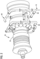
- Fig. 2 illustrates a perspective view of a gas turbine engine 50.
- Piping 60 is attached to the outer casing 55 for the purpose of bleeding cooling air from the compressor section and directing it to the vanes in the turbine section of the engine for cooling purposes.
- compressor debris in the form of oxidation and airborne particulates may also exist in the cooling air flow which may clog the cooling holes 40 of the vanes.
- a dead leg extractor 70,80 may be installed on the existing piping 60 attached to the outer casing 55 of the turbine engine.
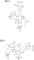
- FIG. 3 illustrates the dead leg extractor 70 in a vertical orientation
- Fig. 4 illustrates a horizontal orientation of the dead leg extractor 80.
- the embodiments shown include design features that enhance the amount and type of debris captured by the dead leg extractor 70, 80 while retaining the debris and preventing their escape back into the flow stream. Additionally, the embodiments allow for online removal or purging of the debris from the dead leg to permit the turbine 50 to be operated continuously without having to be shut down for dead leg cleaning.
- a cooling flow flows vertically through the piping 60 within an inlet pipe 61 until it reaches a piping junction 65.
- the cooling air continues to flow within the piping 60 through an outlet pipe 63, as shown by the arrows.
- Debris, having a higher density than the cooling air flow, by inertia, is projected into a dead leg extractor 70.
- the dead leg extractor 70 may comprise a dead leg 69, which may be a vertical extension of the inlet pipe 61 from the junction 65 as shown, and a ringed pipe segment 67.
- the ringed pipe segment 67 is a cone.
- the cone 67 in the dead leg extractor 70, 80 functions as a means to capture and retain the debris that enters the dead leg 69.
- the incorporation of a cone geometry in the dead leg 69 has been shown through laboratory testing to significantly reduce the amount of debris lost over time once captured in the dead leg 69, especially micron sized debris.
- the cone 67 includes a first opening through which a flow containing debris enters, a smaller second opening through which the flow exits and a height.
- An outer diameter of the cone 67 at the first opening may abut an inner diameter of the dead leg pipe 69 such that the entire flow enters the first opening.
- the height of the cone lies in a range of 8.5 to 16.5 x2,54cm.
- the second opening of the cone lies in a range of 4 to 6 x2,54cm. While some ranges have been given, it should be appreciated that other cone geometries may be used depending on the flow characteristics and piping characteristics involved in the implementation.
- the system may include a cutback feature 72. Testing has shown that approximately 10% of the debris would impinge on the corner of the joint at the junction 65 and flow downstream into the outlet pipe 63 with the cooling flow without such a cutback feature. With a cutback feature 72, the debris is more likely to enter the dead leg 69 instead.
- the cutback feature 72 may comprise angling the pipe at the lower portion of the joint so that debris is drawn down into the dead leg 69.
- the system may include the incorporation of a blow down valve 74 connected at an end of the dead leg 70, 80 opposite the junction 65.
- the blow down valve 74 may open periodically on a timer in order to blow out debris.
- the blow down valve 74 allows the dead leg 69 to be purged of debris (due to the positive internal pressure) while the system is operating.
- the purged debris may be disposed into a solid waste container, for example. No shut down would be required to clean the dead leg 69, as would be case with a traditional filter application such as the witch hat implementation.
- the pipe geometry may be optimized for both vertically and horizontally oriented dead legs 70, 80 to maximize debris capture and retention.
- a horizontal portion of the dead leg containing the cone 67 may have a slight downward slope ending in an elbow that flows into a vertically oriented portion of the dead leg 69.
- a blow down valve 74 may be disposed at the end of the vertically oriented portion. The slight downward slope allows gravity to prevent debris from accumulating underneath the cone 67, instead drawing it towards the blow down valve 74. In an embodiment, the slight downward slope lies in a range of 5-15 degrees.
- the proposed system and method reduces the risk of downstream damage, particularly to vanes of a gas turbine, in a turbine system.
- the proposed dead leg extractor can be implemented quickly, causes little if any decrease in cooling flow, carries low risk, takes up little piping space and requires little if any maintenance.
- the dead leg extractor may simply be installed onto the existing piping of a gas turbine engine as shown in the Fig. 2 .
- the dead leg extractor is further relatively inexpensive to manufacture and provides a simple solution that may be installed on newly manufactured turbines as well as already existing turbines.
Landscapes
- Engineering & Computer Science (AREA)
- Mechanical Engineering (AREA)
- General Engineering & Computer Science (AREA)
- Chemical & Material Sciences (AREA)
- Combustion & Propulsion (AREA)
- Turbine Rotor Nozzle Sealing (AREA)
Claims (8)
- System zur Entfernung von Teilchen aus einem Strömungspfad eines Kühlstroms, das Folgendes umfasst:eine Turbine (50), umfassend zumindest ein Tragflächenprofil (10), mit dem ein Kühlstrom verbunden ist, wobei der Kühlstrom durch die Kühllöcher (40) im Tragflächenprofil (10) strömt, um das Tragflächenprofil (10) zu kühlen, wobei der Kühlstrom mit den Kühllöchern (40) über eine Verrohrung (60) verbunden ist, die ein Einlassrohr (61), ein Auslassrohr (63), eine Abzweigung (65) zwischen dem Einlassrohr (61) und dem Auslassrohr (63) und einen Totzweig für die Teilchenabscheidung (70, 80) umfasst, wobei der Totzweig für die Teilchenabscheidung (70, 80) einen Totzweig (69) umfasst, der eine Verlängerung des Einlassrohres (61) von der Abzweigung (65) ist,wobei der Totzweig für die Teilchenabscheidung (70, 80) ein Mittel zum kontinuierlichen Einfangen und Halten von Teilchen aus dem Kühlstrom während eines Online-Betriebs der Turbine (50) umfasst,dadurch gekennzeichnet, dassder Totzweig für die Teilchenabscheidung (70, 80) ferner einen Kegel (67) innerhalb des Totzweigs (69) als das Mittel zum Einfangen und Halten von Teilchen und ein Abblaseventil (74), das an einem Ende des Totzweigs (70, 8) gegenüber der Abzweigung (65) verbunden ist, umfasst,wobei in einem Fall, dass der Kühlstrom vertikal im Inneren des Einlassrohres (61) strömt, der Totzweig eine vertikale Verlängerung des Einlassrohres (61) ist,wobei in einem Fall, in dem der Kühlstrom horizontal im Inneren des Einlassrohres (61) strömt, der Totzweig eine horizontale Verlängerung des Einlassrohres (61) ist und einen Teil mit einer leichten Abwärtsneigung umfasst, der den Kegel (67) enthält, verbunden mit einem vertikalen Teil, der das Abblaseventil (74) enthält, undwobei sich das Abblaseventil (74) über einen Timer periodisch öffnen kann, um Teilchen auszublasen.
- System nach Anspruch 1, wobei der Kegel (67) eine erste Öffnung, durch die der Kühlstrom eintritt, eine kleinere zweite Öffnung, durch die der Kühlstrom austritt, und eine Höhe umfasst,wobei ein Außendurchmesser des Kegels (67) an der ersten Öffnung an einem Innendurchmesser des Totzweigs für die Teilchenabscheidung (70, 80) anliegt, sodass der gesamte Kühlstrom in die erste Öffnung eintritt, undwobei der Kegel (67) Teilchen aus dem Kühlstrom einfängt und die Teilchen im Totzweig (69) hält.
- System nach Anspruch 2, wobei die Höhe des Kegels 67 in einem Bereich von 8,5 x 2,54 cm bis 16,5 x 2,54 cm ist.
- System nach Anspruch 2 oder 3, wobei der Durchmesser der zweiten Öffnung in einem Bereich von 4-6 x 2,54 cm ist.
- System nach einem der Ansprüche 1 bis 4, wobei der Totzweig für die Teilchenabscheidung (70, 80) eine Reduktion (72) an der Abzweigung (65) zwischen dem Einlassrohr 61 und dem Auslassrohr (63) umfasst.
- System nach Anspruch 1, wobei die leichte Abwärtsneigung in einem Bereich von 5-15 Grad liegt.
- System nach einem der Ansprüche 1 bis 6, wobei das Tragflächenprofil eine Turbinenschaufel (10) ist.
- Verfahren zur Entfernung von Teilchen aus einem Kühlstrom, der mit Kühllöchern (40) eines Tragflächenprofils (10) in einer Turbine (50) verbunden ist, das Folgendes umfasst:Installieren eines Systems nach einem der Ansprüche 1 bis 7,kontinuierliches Extrahieren von Teilchen aus dem Kühlstrom über den Totzweig für die Teilchenabscheidung (70, 80) während des Betriebs der Turbine (50), undBeseitigen der Teilchen im Totzweig (69) durch automatisches periodisches Öffnen des Abblaseventils 74 gemäß einem Timer über eine entsprechende Steuerung.
Applications Claiming Priority (3)
| Application Number | Priority Date | Filing Date | Title |
|---|---|---|---|
| US201762554839P | 2017-09-06 | 2017-09-06 | |
| US201862620738P | 2018-01-23 | 2018-01-23 | |
| PCT/US2018/049449 WO2019050879A1 (en) | 2017-09-06 | 2018-09-05 | DEAD END DEBRIS EXTRACTOR FOR CONTINUOUS LINE OPERATION |
Publications (2)
| Publication Number | Publication Date |
|---|---|
| EP3679227A1 EP3679227A1 (de) | 2020-07-15 |
| EP3679227B1 true EP3679227B1 (de) | 2024-11-27 |
Family
ID=63678694
Family Applications (1)
| Application Number | Title | Priority Date | Filing Date |
|---|---|---|---|
| EP18773917.2A Active EP3679227B1 (de) | 2017-09-06 | 2018-09-05 | Totzweig für die teilchenabscheidung für den kontinuierlichen online-betrieb |
Country Status (3)
| Country | Link |
|---|---|
| US (1) | US10920608B2 (de) |
| EP (1) | EP3679227B1 (de) |
| WO (1) | WO2019050879A1 (de) |
Family Cites Families (14)
| Publication number | Priority date | Publication date | Assignee | Title |
|---|---|---|---|---|
| US2806551A (en) * | 1951-10-16 | 1957-09-17 | Oswald X Heinrich | Centrifugal dust collector with laminar gas flow |
| US5039317A (en) * | 1990-07-05 | 1991-08-13 | Allied-Signal Inc. | Radial inflow particle separation method and apparatus |
| NO318709B1 (no) * | 2000-12-22 | 2005-05-02 | Statoil Asa | Innretning for separasjon av en vaeske fra en flerfase-fluidstrom |
| EP1640587B1 (de) * | 2004-09-22 | 2008-07-09 | Siemens Aktiengesellschaft | Kühlsystem für eine Gasturbine und Verfahren zum Kühlen einer Gasturbine |
| DE112007000718A5 (de) * | 2006-03-31 | 2009-02-26 | Alstom Technology Ltd. | Dampfturbinenanlage und zugehöriges Betriebsverfahren |
| US8176720B2 (en) | 2009-09-22 | 2012-05-15 | Siemens Energy, Inc. | Air cooled turbine component having an internal filtration system |
| JP5683336B2 (ja) | 2011-03-14 | 2015-03-11 | 三菱重工業株式会社 | ガスタービン |
| US20130145747A1 (en) * | 2011-12-07 | 2013-06-13 | Illinois Valley Holding Company | Particulate trap regeneration |
| US8876961B2 (en) * | 2012-02-21 | 2014-11-04 | Mann+Hummel Gmbh | Particle separator with deflector and lateral opening and air filter system |
| WO2014025647A2 (en) * | 2012-08-08 | 2014-02-13 | Illinois Valley Holding Company | Non-thermal particulate filter regeneration |
| JP6021540B2 (ja) * | 2012-09-12 | 2016-11-09 | 三菱日立パワーシステムズ株式会社 | 捕集装置及びこれを備えるガスタービンプラント |
| US9897006B2 (en) | 2015-06-15 | 2018-02-20 | General Electric Company | Hot gas path component cooling system having a particle collection chamber |
| US10563579B2 (en) * | 2015-11-18 | 2020-02-18 | Rolls-Royce North American Technologies Inc. | Air-inlet duct having a particle separator and an agglomerator for a gas turbine engine |
| US10294823B2 (en) * | 2016-05-23 | 2019-05-21 | United Technologies Corporation | Dirt evacuation devices |
-
2018
- 2018-09-05 US US16/644,694 patent/US10920608B2/en active Active
- 2018-09-05 EP EP18773917.2A patent/EP3679227B1/de active Active
- 2018-09-05 WO PCT/US2018/049449 patent/WO2019050879A1/en not_active Ceased
Also Published As
| Publication number | Publication date |
|---|---|
| WO2019050879A1 (en) | 2019-03-14 |
| EP3679227A1 (de) | 2020-07-15 |
| US10920608B2 (en) | 2021-02-16 |
| US20200291814A1 (en) | 2020-09-17 |
Similar Documents
| Publication | Publication Date | Title |
|---|---|---|
| CN105531012B (zh) | 用于燃气涡轮的过滤室及其维护方法 | |
| JP5779583B2 (ja) | 遠心圧縮機のための小滴キャッチャ | |
| US10322621B2 (en) | Inertial particle separator for air cycle machine | |
| CN204877682U (zh) | 用于涡轮机的碎片清除系统及对应的涡轮机 | |
| CN110139976B (zh) | 用于涡轮发动机的颗粒分离器组件 | |
| JP2010151132A (ja) | ターボ機械に流入する空気流から異物を除去するシステム及び方法 | |
| US8146445B2 (en) | Extractive probe for hot flue gas and process measurement | |
| US10265651B2 (en) | Compact water extractor | |
| EP1760260A2 (de) | Schmutzabscheider für die Luftzufuhr in einer Gasturbine und Gasturbine mit einem solchen Schmutzabscheider | |
| CN110319055A (zh) | 一种油烟分离风机的叶轮 | |
| CN104028052A (zh) | 一种气体净化设备 | |
| US11511222B2 (en) | Anti-contamination baffle for cooling air systems | |
| US10920608B2 (en) | Dead leg debris extractor for continuous on-line operation | |
| CN209005397U (zh) | 一种螺旋渐扩除尘器 | |
| RU2226121C1 (ru) | Инерционный очиститель газа | |
| CN111686519B (zh) | 旋风除尘装置 | |
| JP2020512556A (ja) | 原子炉における給水スパージャのノズルとその使用方法 | |
| CN113217901A (zh) | 一种颗粒物清除装置 | |
| CN209392890U (zh) | 一种高温烟气除尘装置 | |
| CN107716481B (zh) | 超临界二氧化碳系统锅炉吹管装置及方法 | |
| KR101647261B1 (ko) | 가스터빈의 이물질 제거장치 | |
| JP4051013B2 (ja) | オイルエリミネーター及び油脂分離回収装置 | |
| JPH0714450B2 (ja) | 集塵装置 | |
| JPS60166702A (ja) | ガスタ−ビンコンプレツサ翼の汚れ検知装置 | |
| JPH09262422A (ja) | 高温ガス用除塵装置 |
Legal Events
| Date | Code | Title | Description |
|---|---|---|---|
| STAA | Information on the status of an ep patent application or granted ep patent |
Free format text: STATUS: UNKNOWN |
|
| STAA | Information on the status of an ep patent application or granted ep patent |
Free format text: STATUS: THE INTERNATIONAL PUBLICATION HAS BEEN MADE |
|
| PUAI | Public reference made under article 153(3) epc to a published international application that has entered the european phase |
Free format text: ORIGINAL CODE: 0009012 |
|
| STAA | Information on the status of an ep patent application or granted ep patent |
Free format text: STATUS: REQUEST FOR EXAMINATION WAS MADE |
|
| 17P | Request for examination filed |
Effective date: 20200306 |
|
| AK | Designated contracting states |
Kind code of ref document: A1 Designated state(s): AL AT BE BG CH CY CZ DE DK EE ES FI FR GB GR HR HU IE IS IT LI LT LU LV MC MK MT NL NO PL PT RO RS SE SI SK SM TR |
|
| AX | Request for extension of the european patent |
Extension state: BA ME |
|
| DAV | Request for validation of the european patent (deleted) | ||
| DAX | Request for extension of the european patent (deleted) | ||
| STAA | Information on the status of an ep patent application or granted ep patent |
Free format text: STATUS: EXAMINATION IS IN PROGRESS |
|
| 17Q | First examination report despatched |
Effective date: 20210610 |
|
| GRAP | Despatch of communication of intention to grant a patent |
Free format text: ORIGINAL CODE: EPIDOSNIGR1 |
|
| STAA | Information on the status of an ep patent application or granted ep patent |
Free format text: STATUS: GRANT OF PATENT IS INTENDED |
|
| INTG | Intention to grant announced |
Effective date: 20240618 |
|
| GRAS | Grant fee paid |
Free format text: ORIGINAL CODE: EPIDOSNIGR3 |
|
| GRAA | (expected) grant |
Free format text: ORIGINAL CODE: 0009210 |
|
| STAA | Information on the status of an ep patent application or granted ep patent |
Free format text: STATUS: THE PATENT HAS BEEN GRANTED |
|
| AK | Designated contracting states |
Kind code of ref document: B1 Designated state(s): AL AT BE BG CH CY CZ DE DK EE ES FI FR GB GR HR HU IE IS IT LI LT LU LV MC MK MT NL NO PL PT RO RS SE SI SK SM TR |
|
| REG | Reference to a national code |
Ref country code: GB Ref legal event code: FG4D |
|
| REG | Reference to a national code |
Ref country code: CH Ref legal event code: EP |
|
| REG | Reference to a national code |
Ref country code: DE Ref legal event code: R096 Ref document number: 602018077004 Country of ref document: DE |
|
| REG | Reference to a national code |
Ref country code: IE Ref legal event code: FG4D |
|
| REG | Reference to a national code |
Ref country code: LT Ref legal event code: MG9D |
|
| REG | Reference to a national code |
Ref country code: NL Ref legal event code: MP Effective date: 20241127 |
|
| PG25 | Lapsed in a contracting state [announced via postgrant information from national office to epo] |
Ref country code: HR Free format text: LAPSE BECAUSE OF FAILURE TO SUBMIT A TRANSLATION OF THE DESCRIPTION OR TO PAY THE FEE WITHIN THE PRESCRIBED TIME-LIMIT Effective date: 20241127 Ref country code: IS Free format text: LAPSE BECAUSE OF FAILURE TO SUBMIT A TRANSLATION OF THE DESCRIPTION OR TO PAY THE FEE WITHIN THE PRESCRIBED TIME-LIMIT Effective date: 20250327 Ref country code: PT Free format text: LAPSE BECAUSE OF FAILURE TO SUBMIT A TRANSLATION OF THE DESCRIPTION OR TO PAY THE FEE WITHIN THE PRESCRIBED TIME-LIMIT Effective date: 20250327 |
|
| PG25 | Lapsed in a contracting state [announced via postgrant information from national office to epo] |
Ref country code: FI Free format text: LAPSE BECAUSE OF FAILURE TO SUBMIT A TRANSLATION OF THE DESCRIPTION OR TO PAY THE FEE WITHIN THE PRESCRIBED TIME-LIMIT Effective date: 20241127 Ref country code: NL Free format text: LAPSE BECAUSE OF FAILURE TO SUBMIT A TRANSLATION OF THE DESCRIPTION OR TO PAY THE FEE WITHIN THE PRESCRIBED TIME-LIMIT Effective date: 20241127 |
|
| REG | Reference to a national code |
Ref country code: AT Ref legal event code: MK05 Ref document number: 1745879 Country of ref document: AT Kind code of ref document: T Effective date: 20241127 |
|
| PG25 | Lapsed in a contracting state [announced via postgrant information from national office to epo] |
Ref country code: BG Free format text: LAPSE BECAUSE OF FAILURE TO SUBMIT A TRANSLATION OF THE DESCRIPTION OR TO PAY THE FEE WITHIN THE PRESCRIBED TIME-LIMIT Effective date: 20241127 |
|
| PG25 | Lapsed in a contracting state [announced via postgrant information from national office to epo] |
Ref country code: ES Free format text: LAPSE BECAUSE OF FAILURE TO SUBMIT A TRANSLATION OF THE DESCRIPTION OR TO PAY THE FEE WITHIN THE PRESCRIBED TIME-LIMIT Effective date: 20241127 |
|
| PG25 | Lapsed in a contracting state [announced via postgrant information from national office to epo] |
Ref country code: NO Free format text: LAPSE BECAUSE OF FAILURE TO SUBMIT A TRANSLATION OF THE DESCRIPTION OR TO PAY THE FEE WITHIN THE PRESCRIBED TIME-LIMIT Effective date: 20250227 |
|
| PG25 | Lapsed in a contracting state [announced via postgrant information from national office to epo] |
Ref country code: LV Free format text: LAPSE BECAUSE OF FAILURE TO SUBMIT A TRANSLATION OF THE DESCRIPTION OR TO PAY THE FEE WITHIN THE PRESCRIBED TIME-LIMIT Effective date: 20241127 Ref country code: AT Free format text: LAPSE BECAUSE OF FAILURE TO SUBMIT A TRANSLATION OF THE DESCRIPTION OR TO PAY THE FEE WITHIN THE PRESCRIBED TIME-LIMIT Effective date: 20241127 Ref country code: GR Free format text: LAPSE BECAUSE OF FAILURE TO SUBMIT A TRANSLATION OF THE DESCRIPTION OR TO PAY THE FEE WITHIN THE PRESCRIBED TIME-LIMIT Effective date: 20250228 |
|
| PG25 | Lapsed in a contracting state [announced via postgrant information from national office to epo] |
Ref country code: PL Free format text: LAPSE BECAUSE OF FAILURE TO SUBMIT A TRANSLATION OF THE DESCRIPTION OR TO PAY THE FEE WITHIN THE PRESCRIBED TIME-LIMIT Effective date: 20241127 |
|
| PG25 | Lapsed in a contracting state [announced via postgrant information from national office to epo] |
Ref country code: RS Free format text: LAPSE BECAUSE OF FAILURE TO SUBMIT A TRANSLATION OF THE DESCRIPTION OR TO PAY THE FEE WITHIN THE PRESCRIBED TIME-LIMIT Effective date: 20250227 |
|
| PG25 | Lapsed in a contracting state [announced via postgrant information from national office to epo] |
Ref country code: SM Free format text: LAPSE BECAUSE OF FAILURE TO SUBMIT A TRANSLATION OF THE DESCRIPTION OR TO PAY THE FEE WITHIN THE PRESCRIBED TIME-LIMIT Effective date: 20241127 |
|
| PG25 | Lapsed in a contracting state [announced via postgrant information from national office to epo] |
Ref country code: DK Free format text: LAPSE BECAUSE OF FAILURE TO SUBMIT A TRANSLATION OF THE DESCRIPTION OR TO PAY THE FEE WITHIN THE PRESCRIBED TIME-LIMIT Effective date: 20241127 |
|
| PG25 | Lapsed in a contracting state [announced via postgrant information from national office to epo] |
Ref country code: EE Free format text: LAPSE BECAUSE OF FAILURE TO SUBMIT A TRANSLATION OF THE DESCRIPTION OR TO PAY THE FEE WITHIN THE PRESCRIBED TIME-LIMIT Effective date: 20241127 |
|
| PG25 | Lapsed in a contracting state [announced via postgrant information from national office to epo] |
Ref country code: RO Free format text: LAPSE BECAUSE OF FAILURE TO SUBMIT A TRANSLATION OF THE DESCRIPTION OR TO PAY THE FEE WITHIN THE PRESCRIBED TIME-LIMIT Effective date: 20241127 |
|
| PG25 | Lapsed in a contracting state [announced via postgrant information from national office to epo] |
Ref country code: SK Free format text: LAPSE BECAUSE OF FAILURE TO SUBMIT A TRANSLATION OF THE DESCRIPTION OR TO PAY THE FEE WITHIN THE PRESCRIBED TIME-LIMIT Effective date: 20241127 |
|
| PG25 | Lapsed in a contracting state [announced via postgrant information from national office to epo] |
Ref country code: CZ Free format text: LAPSE BECAUSE OF FAILURE TO SUBMIT A TRANSLATION OF THE DESCRIPTION OR TO PAY THE FEE WITHIN THE PRESCRIBED TIME-LIMIT Effective date: 20241127 |
|
| PG25 | Lapsed in a contracting state [announced via postgrant information from national office to epo] |
Ref country code: IT Free format text: LAPSE BECAUSE OF FAILURE TO SUBMIT A TRANSLATION OF THE DESCRIPTION OR TO PAY THE FEE WITHIN THE PRESCRIBED TIME-LIMIT Effective date: 20241127 |
|
| REG | Reference to a national code |
Ref country code: DE Ref legal event code: R097 Ref document number: 602018077004 Country of ref document: DE |
|
| PG25 | Lapsed in a contracting state [announced via postgrant information from national office to epo] |
Ref country code: SE Free format text: LAPSE BECAUSE OF FAILURE TO SUBMIT A TRANSLATION OF THE DESCRIPTION OR TO PAY THE FEE WITHIN THE PRESCRIBED TIME-LIMIT Effective date: 20241127 |
|
| PLBE | No opposition filed within time limit |
Free format text: ORIGINAL CODE: 0009261 |
|
| STAA | Information on the status of an ep patent application or granted ep patent |
Free format text: STATUS: NO OPPOSITION FILED WITHIN TIME LIMIT |
|
| REG | Reference to a national code |
Ref country code: CH Ref legal event code: L10 Free format text: ST27 STATUS EVENT CODE: U-0-0-L10-L00 (AS PROVIDED BY THE NATIONAL OFFICE) Effective date: 20251008 |
|
| PGFP | Annual fee paid to national office [announced via postgrant information from national office to epo] |
Ref country code: DE Payment date: 20250926 Year of fee payment: 8 |
|
| 26N | No opposition filed |
Effective date: 20250828 |
|
| REG | Reference to a national code |
Ref country code: CH Ref legal event code: H13 Free format text: ST27 STATUS EVENT CODE: U-0-0-H10-H13 (AS PROVIDED BY THE NATIONAL OFFICE) Effective date: 20260504 |
|
| PG25 | Lapsed in a contracting state [announced via postgrant information from national office to epo] |
Ref country code: LU Free format text: LAPSE BECAUSE OF NON-PAYMENT OF DUE FEES Effective date: 20250905 |
|
| GBPC | Gb: european patent ceased through non-payment of renewal fee |
Effective date: 20250905 |
|
| REG | Reference to a national code |
Ref country code: BE Ref legal event code: MM Effective date: 20250930 |
|
| PG25 | Lapsed in a contracting state [announced via postgrant information from national office to epo] |
Ref country code: LT Free format text: LAPSE BECAUSE OF FAILURE TO SUBMIT A TRANSLATION OF THE DESCRIPTION OR TO PAY THE FEE WITHIN THE PRESCRIBED TIME-LIMIT Effective date: 20241127 |
|
| PG25 | Lapsed in a contracting state [announced via postgrant information from national office to epo] |
Ref country code: MC Free format text: LAPSE BECAUSE OF FAILURE TO SUBMIT A TRANSLATION OF THE DESCRIPTION OR TO PAY THE FEE WITHIN THE PRESCRIBED TIME-LIMIT Effective date: 20241127 |
|
| PG25 | Lapsed in a contracting state [announced via postgrant information from national office to epo] |
Ref country code: GB Free format text: LAPSE BECAUSE OF NON-PAYMENT OF DUE FEES Effective date: 20250905 |
|
| PG25 | Lapsed in a contracting state [announced via postgrant information from national office to epo] |
Ref country code: IE Free format text: LAPSE BECAUSE OF NON-PAYMENT OF DUE FEES Effective date: 20250905 Ref country code: CH Free format text: LAPSE BECAUSE OF NON-PAYMENT OF DUE FEES Effective date: 20250930 Ref country code: BE Free format text: LAPSE BECAUSE OF NON-PAYMENT OF DUE FEES Effective date: 20250930 |
|
| PG25 | Lapsed in a contracting state [announced via postgrant information from national office to epo] |
Ref country code: FR Free format text: LAPSE BECAUSE OF NON-PAYMENT OF DUE FEES Effective date: 20250930 |