EP3679247B1 - Procédé d'analyse de données de capteur relatives à une éolienne - Google Patents
Procédé d'analyse de données de capteur relatives à une éolienne Download PDFInfo
- Publication number
- EP3679247B1 EP3679247B1 EP18769961.6A EP18769961A EP3679247B1 EP 3679247 B1 EP3679247 B1 EP 3679247B1 EP 18769961 A EP18769961 A EP 18769961A EP 3679247 B1 EP3679247 B1 EP 3679247B1
- Authority
- EP
- European Patent Office
- Prior art keywords
- deviation
- image
- images
- data
- blade
- Prior art date
- Legal status (The legal status is an assumption and is not a legal conclusion. Google has not performed a legal analysis and makes no representation as to the accuracy of the status listed.)
- Active
Links
Images

Classifications
-
- F—MECHANICAL ENGINEERING; LIGHTING; HEATING; WEAPONS; BLASTING
- F03—MACHINES OR ENGINES FOR LIQUIDS; WIND, SPRING, OR WEIGHT MOTORS; PRODUCING MECHANICAL POWER OR A REACTIVE PROPULSIVE THRUST, NOT OTHERWISE PROVIDED FOR
- F03D—WIND MOTORS
- F03D17/00—Monitoring or testing of wind motors, e.g. diagnostics
-
- F—MECHANICAL ENGINEERING; LIGHTING; HEATING; WEAPONS; BLASTING
- F03—MACHINES OR ENGINES FOR LIQUIDS; WIND, SPRING, OR WEIGHT MOTORS; PRODUCING MECHANICAL POWER OR A REACTIVE PROPULSIVE THRUST, NOT OTHERWISE PROVIDED FOR
- F03D—WIND MOTORS
- F03D80/00—Details, components or accessories not provided for in groups F03D1/00 - F03D17/00
- F03D80/50—Maintenance or repair
-
- F—MECHANICAL ENGINEERING; LIGHTING; HEATING; WEAPONS; BLASTING
- F05—INDEXING SCHEMES RELATING TO ENGINES OR PUMPS IN VARIOUS SUBCLASSES OF CLASSES F01-F04
- F05B—INDEXING SCHEME RELATING TO WIND, SPRING, WEIGHT, INERTIA OR LIKE MOTORS, TO MACHINES OR ENGINES FOR LIQUIDS COVERED BY SUBCLASSES F03B, F03D AND F03G
- F05B2260/00—Function
- F05B2260/80—Diagnostics
-
- F—MECHANICAL ENGINEERING; LIGHTING; HEATING; WEAPONS; BLASTING
- F05—INDEXING SCHEMES RELATING TO ENGINES OR PUMPS IN VARIOUS SUBCLASSES OF CLASSES F01-F04
- F05B—INDEXING SCHEME RELATING TO WIND, SPRING, WEIGHT, INERTIA OR LIKE MOTORS, TO MACHINES OR ENGINES FOR LIQUIDS COVERED BY SUBCLASSES F03B, F03D AND F03G
- F05B2270/00—Control
- F05B2270/80—Devices generating input signals, e.g. transducers, sensors, cameras or strain gauges
- F05B2270/804—Optical devices
- F05B2270/8041—Cameras
-
- Y—GENERAL TAGGING OF NEW TECHNOLOGICAL DEVELOPMENTS; GENERAL TAGGING OF CROSS-SECTIONAL TECHNOLOGIES SPANNING OVER SEVERAL SECTIONS OF THE IPC; TECHNICAL SUBJECTS COVERED BY FORMER USPC CROSS-REFERENCE ART COLLECTIONS [XRACs] AND DIGESTS
- Y02—TECHNOLOGIES OR APPLICATIONS FOR MITIGATION OR ADAPTATION AGAINST CLIMATE CHANGE
- Y02E—REDUCTION OF GREENHOUSE GAS [GHG] EMISSIONS, RELATED TO ENERGY GENERATION, TRANSMISSION OR DISTRIBUTION
- Y02E10/00—Energy generation through renewable energy sources
- Y02E10/70—Wind energy
- Y02E10/72—Wind turbines with rotation axis in wind direction
Definitions
- the invention relates to the field of plant inspection, and in particular to a method for analysing sensor data related to a wind turbine.
- Turbine blades typically are made of fibre-reinforced composites, with resins such as polyester and epoxy, and with glass and carbon fibres as the reinforcing material. Defects of the blades can be caused by the impact of objects, lightning, erosion by rain and hail, mechanical stress and flexing, aging, etc. Owners and operators should obtain full transparency with respect to the health of their assets. The detailed knowledge about defects and their propagation over time is the most important prerequisite for preventive maintenance and repair, which are known to unlock great cost savings. In addition, it facilitates compliance with legislation and with requirements by insurance companies. For this reason, rotor blades and wind-turbine towers have to be inspected periodically.
- Such inspections are carried out manually by rope access teams.
- Highly trained inspection climbers visually identify defects over a blade surface of up to 500m 2 and record anomalies with handheld cameras.
- Current issues with traditional rope access inspection include: an aging plant population, requiring frequent inspections, increasing size of the turbines, with blades longer than 60 meters and towers higher than 100 meters, the inspection quality depends on the subjective judgement of the climbers, adverse weather conditions may limit the inspector's performance, damages can be detected by the rope team but full coverage and seamless digital documentation of the blade's health cannot be assured, reports are created mostly manually.
- the method for analysis of sensor data related to a wind turbine comprises the steps of
- the enhanced sensor data can be the result of an inspection mission which comprises an inspection pattern with settings or reference data for a UAV, for inspection sensors (such as a camera) and for sensors for navigation, and which defines positions of the UAV at which sensor readings (such as images) are to be taken, and/or areas or points to be inspected or photographed. positions of the UAV at which sensor readings (such as images) are to be taken, and/or areas or points to be inspected or photographed.
- the sensor data that is, each set of sensor data, is stored in combination with sensor metadata.
- This combination shall be called enhanced sensor data.
- the sensor data can in particular be image data.
- the sensor metadata can in particular comprise sensor pose data. Pose data describes the pose of an object in 3D space, that is the combination of its position and orientation. Further sensor metadata can describe parameters of the inspection sensor related to the captured sensor data. For example, if the sensor is a camera, the sensor metadata can be exposure time, focus settings, etc.
- storing each set of sensor data in association with sensor pose data comprises the steps of, during an inspection mission:
- the different data can be stored in association with a mission identifier that uniquely identifies the inspection mission and permits to link the data to mission data that characterises the mission as a whole, such as an identity of the turbine, a model type of the turbine, its geographic location, its owner or operator, etc...
- the reference flight path can be in terms of the trajectory and pose of the UAV or the trajectory and pose of the inspection sensor. The two are related by their relative position and the gimbal angles.
- the senor is a camera and the sensor data is image data, and the step of
- an image browser can be provided which allows for an integrated view of a plurality of images of the blade, in a manner that corresponds to the physical configuration of the inspection sensor or camera relative to the blade at the instant that the images were taken.
- images being “associated with the same vertical position” does not necessarily mean that the vertical positions are exactly the same, but can differ to a certain degree. Or it can mean that a vertical position comprised in the respective sensor pose data lies within a band of vertical positions of a given width.
- a vertical position comprised in the respective sensor pose data lies within a band of vertical positions of a given width.
- the images associated with the same horizontal position are captured as a sequence of images as the UAV follows an essentially vertical section of its flight path.
- the method comprises the step of displaying at least two images in a vertical column, and scrolling, according to a user input, the column in a vertical direction on the display device.
- the method comprises the steps of
- the horizontal position can be chosen to be the same in image coordinates. Alternatively, it can be chosen to be the same horizontal position on the blade, e.g. in a coordinate system of the blade (or "blade coordinates"), wherein the horizontal position can be defined and measured along the chord lines.
- the method comprises the steps of
- the selected linear feature can be, for example, the leading edge or trailing edge, a seam line or a weld line on the surface of the blade.
- the computer model of the blade which also comprises such linear features, and since the images can be mapped onto the model, the position of a feature in the model can be projected back into the images and used to select the portion of the image to be displayed in the magnified section.
- the senor is a camera and the sensor data is image data, and the step of
- deviation represents changes to the surface of a blade 3 that deviate from a normal or original state of the surface.
- a deviation is a defect, or a patch caused by repairing a defect.
- deviations are caused by events that change the state of the surface. Such events can be damage events or repair or maintenance events.
- Deviation data is a set of information describing a deviation. It can comprise one or more deviation images, a deviation categorization and a deviation location.
- a deviation image is a sub-image cut from an image along a bounding line, typically a bounding box.
- the deviation categorization comprises a type, severity, etc. of the deviation. It can also comprise an action recommendation, indicating a type of action for repairing a defect.
- the different data comprised by deviation data regarding a particular deviation or defect can be stored in association with a unique deviation identifier.
- the deviation location generally corresponds to the location of the deviation in 3D space. It can be can expressed in terms of a 3D reference system external to the blade, or one fixed to the blade, or in terms of a two-dimensional blade coordinate system on the surface of the blade. Therein, for example, one coordinate can give the position as measured from the root of the blade, the other the position on a chord line, measured from one of the edges
- the method comprises (for identifying deviations on the blade) the steps of
- the user input can be inputted by means of a pointing device such as a computer mouse, and by drawing the bounding line or a bounding box at least approximately comprising the deviation image.
- a pointing device such as a computer mouse
- the bounding line can be determined automatically from a single point of the deviation image. This point can be selected by the user or can be determined automatically.
- the bounding line or box can be determined automatically, for example, by using a standard box size or by determining an image patch around the selected point that shares image properties such as colour and/or structure with the selected point.
- This (determining a deviation location) can be done given the sensor pose data associated with the image and the 3D computer model of the blade.
- the sensor pose data allows to determine the relative position of the camera to the real blade at the time that the image was taken.
- the geometry of the camera is known, and can depend on settings of the camera, such as zoom and focus settings, which are part of the sensor metadata. This information allows to project, within the 3D computer model, a point in the image coordinate system back onto the 3D model of the blade and thereby determine the position on the blade.
- the location of the deviation image within the image can be determined from the bounding line, for example, as the centre of gravity of the image section determined by the bounding line.
- the method comprises (for identifying deviations on the blade) the steps of
- the step of automatically determining the location of the deviation image within the image can be part of the preceding computer-implemented analysis.
- it can be an output of an analysis performed with a convolutional neural network (CNN) or another machine learning method.
- CNN convolutional neural network
- it can be determined by the steps of
- the method comprises the steps of
- a deviation categorization comprises properties of the deviation. Further elements of a deviation categorization can comprise other deviation properties such as a size of the deviation. This can be expressed in blade coordinates. It can comprise a maximum elongation in each of the two coordinate directions.
- automatically determining the deviation categorization comprises the use of a classification method derived by supervised machine learning.
- a training set of deviation images with associated deviation categorizations that were established manually can be used to train a classification algorithm that will perform the automatic classification based on fresh deviation images.
- Such algorithms can use, for example, convolutional neural networks (CNN).
- the classification method can use as input, in addition to a deviation image, the associated deviation location. This allows to take into account the fact that certain defects are more likely to appear at certain locations on the blade. This can improve the efficiency and the quality of the classification. For example, defects due to lightning are more likely to occur near the tip, erosion is more likely to occur on the leading edge, cracks are more likely to occur at locations of high stress (which can be found by FEM simulation of the blade under load), etc.
- the method comprises the steps of
- deviation images extracted from different images are matched, showing the same physical deviation from different viewpoints and/or at different points in time.
- the comparing of the deviation location can be done automatically.
- the different viewpoints typically correspond to images or generally enhanced sensor data captured during the same inspection mission inspecting a single blade.
- the different points in time typically correspond to separate inspection missions inspecting the same blade at different times, e.g., months or years apart.
- the method comprises the step of
- a turbine operator can demonstrate compliance with legal and insurance companies' requirements.
- technical requirements can be specified to ensure safe and efficient operation of the turbine. Showing that a turbine or blade satisfies the requirements can help to extend the lifetime of the blade and/or the turbine.
- the method comprises the steps of
- deviation history data Such sets of deviation data from different inspections but pertaining to the same physical deviation can be called deviation history data.
- defect history data For a deviation that represents a defect that has not been repaired, it can also be called defect history data.
- Deviation history data can be augmented by information about repairs having taken place. Such information can be added manually. As a result, the deviation history data covers, for each deviation, its initial evolution as a defect, then a maintenance action such as repairing the defect, and then the further evolution of the repaired deviation, all at the same location on the blade.
- images from at least one earlier inspection mission are used in performing a computer-implemented analysis of an image to identify one or more deviation images, by comparing an image to an image of the same location on the blade from an earlier inspection mission. This makes it possible to identify deviations based on a difference in images, and/or to identify changes to a deviation over time.
- an analysis of defect progression over time is performed from the deviation history data and in particular defect history data from a plurality of inspection missions over a plurality of turbines having comparable types of blades. For example, a statistical model of the evolution of deviation properties as comprised in the deviation categorization can be automatically derived. This corresponds to a model of defect progression for the type of blades considered.
- the sequence of images thus comprises images that are to be displayed, and the manner of displaying them is automatically adapted according to an expected number of deviations This probability of occurrences can be considered as a probability distribution over the area of the blade.
- the probability of occurrences of deviations can also be expressed as an expected density of deviations or defects. For example, this can be a number of expected deviations or defects per image or per unit area within the image.
- the density is a scalar value associated with the image.
- the density has, for different locations in the image, separate values. These values can be represented by a density map associated with the image.
- the density maps of the images in combination, correspond to a density map covering the area of the blade.
- the images being displayed can be the original images or image data, or (processed) images generated by processing the former. Processing the images can involve an adaptation of colour and brightness parameters, and/or combining images by stitching and/or blending them together, or by switching from one image to the next as the virtual camera moves along its flight path. Alternatively or in addition, processing the images can involve a superposition of the images with associated density maps representing the probability of occurrences of deviations within the associated images, for example by a colouring or modification of the images according to the density. In such cases, the virtual flight path can be expressed in a coordinate system related to a plane in which the images lie.
- processing the images can involve generating a virtual view by mapping or projecting images on the computer model of the blade and rendering a view of the blade as seen from a virtual camera.
- the virtual flight path can be expressed in a 3D coordinate system of the computer model of the blade.
- one or more parameters that control the displaying of the sequence of images are from the set of:
- a flight path of a virtual camera - using the original or processed images - can be determined according to the probability of occurrences of deviations, by adapting its parameters, such as speed, distance from the blade (or magnification or zoom factor) and/or direction of view.
- the distance from the blade, or magnification or zoom factor correspond to the size of an area represented by an image.
- the flight path is generated from a reference flight path.
- the reference flight path can be generated from a statistical analysis of defect data across multiple wind turbines and blades of the same type, using defect annotations from human experts.
- the reference flight path can be adapted by modifying virtual camera flight parameters, such as zoom level and viewing direction according to the probability of occurrences of deviations.
- the flight path can be generated by first determining a set of areas with a relatively high expected density of deviations or defects ("hotspots"), then determining a path that covers all these areas (known algorithms for the travelling salesman problem can be used for this). Then, virtual camera flight parameters can be adapted as described above. As explained below, the expected density of deviations or probability of occurrences of deviations can be determined from the images by means of a machine learning system.
- the probability of occurrence of deviations in the image being displayed can be signalled to the user. This can be done by optical, acoustical, haptic (vibration) means, etc.
- Optical means can involve a display element on the display device, such as changing a colour of an area of the screen, changing a position of an indicator element along a scale, etc.
- the image browser software can display one or more of the following data: altitude or vertical position at which image is located, camera ISO, aperture and exposure settings, and/or the focus distance. For each defect or deviation, the location on the blade, e.g. expressed as distance from the blade root and from the leading edge, can also be displayed.
- the steps are performed of.
- the probability of occurrences of deviations within the image can be expressed as a set of one or more deviations, each deviation being associated with a categorization and an expected location in the image and/or on the blade. These two locations carry the same information, since one can be computed from the other. Given a set of deviations from one or more images, a corresponding density of deviations or defects in the images and/or on the blade surface can be computed.
- the position data associated with the image corresponds to its position on the blade. It can be expressed by a position and size (and optionally an angular orientation) of the image in the blade coordinate system and can be computed from the sensor pose data associated with the image.
- Machine learning can involve deep learning architectures such as deep neural networks, deep belief networks and recurrent neural networks.
- the machine learning system can be trained depending on the nature of the data used when applying it.
- training data can comprise images together with image position and size on the blade as input data, and deviation information, such as the probability of occurrences as output data.
- the input data can be image position alone, without regard to image content.
- the senor is a distance sensor and the sensor data is distance data, and the step of
- a set of distance measurements can, depending on the type of sensor, comprise a 2D depth map or a linear sequence of distance measurements from scanning distances within a plane.
- a set of distance measurements is associated with the pose of the distance sensor - which in turn can be determined from the pose of the UAV and the angles of the gimbal - at the time that the measurements were taken.
- This information can be combined, resulting in, for each set of distance measurements, a set of points in 3D space. For a linear scanner, these points lie within a plane in 3D space.
- a plurality of such sets of distance measurements can give, depending on the flight path and pose of the distance sensor, points in 3D space from all parts of the turbine that are of interest.
- the information from these points, representing a point cloud can be integrated in known ways to generate a 3D model from scratch, or to adapt parameters of a given 3D model.
- Methods for adapting parameters of a given 3D model to a point cloud can involve optimisation methods that vary the parameters of the 3D model until it achieves an optimal match with the point cloud.
- Optimisation methods can be deterministic or stochastic.
- Adapting a given model has the advantage that a priori information about the structure of the turbine is incorporated.
- the method comprises the following steps for acquiring sensor data related to a wind turbine, using an unmanned aerial vehicle (UAV) comprising at least one inspection sensor for acquiring the sensor data:
- UAV unmanned aerial vehicle
- a computer program for the analysis of sensor data related to a wind turbine is loadable into an internal memory of a digital computer or a computer system, and comprises computer-executable instructions to cause one or more processors of the computer or computer system execute the analysis method.
- a computer program product comprises a computer readable medium having the computer-executable instructions recorded thereon.
- the computer readable medium preferably is non-transitory; that is, tangible.
- the computer program is embodied as a reproducible computer-readable signal, and thus can be transmitted in the form of such a signal.
- the executing of the method can involve the computer program interacting with a user, by means of output devices such as a display, printer, etc. and input devices such as a keyboard, pointing device, touchscreen, etc.
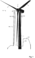
- FIG. 1 schematically shows a wind turbine 10 comprising a tower 1 supporting a nacelle enclosing a drive train driving an electrical generator via a gearbox.
- Turbine blades 3 are arranged on a hub to form a rotor 2 driving the drive train.
- Each blade 3 is typically secured at its root end 32, and then “spans" radially “outboard” to a free end or tip 31.
- the distance from the tip 31 to the root 32, at the opposite end of the blade 3, is called the “span.”
- the front, or leading edge 33 of the blade 3 connects the forward-most points of the blade 3 that first contact the air.
- the rear, or trailing edge 34 of the blade 3 is where airflow that has been separated by the leading edge 33 re-joins after passing over a suction surface or side 35 and a pressure surface or side 36 of the blade.
- chord line connects the leading and trailing edges of the blade 3 in the direction of the typical airflow across the blade.
- the length of the chord line is called the chord. Since many blades 10 change their chord over the span, the chord length is referred to as the "root chord,” near the root, and the “tip chord,” near the tip of the blade.
- the chord lines are arranged in the “chord planes” that extend through the streamlines on the corresponding pressure and suction surfaces of the blade.
- Figure 1 also shows a reference flight path 54a.
- the reference flight path 54a can be generated from a generic flight path 53 by scaling it according to the actual dimensions, expressed by a set of parameters, of the turbine 10 to be inspected.
- the flight path shows several sections 533 along which the UAV 4 moves along the span of the blade 3 on vertical paths, upward or downward. Each such vertical section covers the span of the blade 3, and thus images taken along one section cover one circumferential section of the blade.
- the vertical sections are arranged around the blade 3, and so the images 6 from all vertical sections together can provide a complete view of the surface of the blade 3.
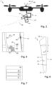
- FIG 2 schematically shows an unmanned aerial vehicle (UAV) 4, such as a multicopter, as it can be used in embodiments of the invention.
- UAV unmanned aerial vehicle
- It carries a inspection sensor 42 suspended by gimbal 41, rotatable about at least two or three Euler angles.
- the inspection sensor 42 typically is an optical camera and shall henceforth be referred to as such. However, other types of inspection sensors can be envisioned, such as devices operating in the non-optical ranges of the electromagnetic spectrum, range sensors etc.
- the camera 42 comprises a focus drive 43 for changing a focus setting of the camera lens.
- a 2D depth map comprises 3D information in that it comprises a 2D array of data, wherein the data indicates the distance from a point (such as a sensor) or in general also from a plane.
- the UAV 4 comprises a GPS 45 module and/or a further sensor 46, such as inertial sensor, gyroscope, barometer and/or compass.
- a flight controller 47 is arranged to integrate data from the GPS 45 and/or further sensor 46 and the distance sensor 44, and a computer model of an object to be inspected, such as a wind turbine 10, and to generate flight commands such as position or speed vectors to be executed by the UAV 4. This can be done by, at a given time and location, determining the pose of the UAV 4, comparing it to the pose according to the reference path, and calculating flight commands based on current pose, velocity and acceleration information to move the UAV to a next pose along the reference path at a future point in time.
- the reference path and the next pose typically includes reference speed vectors.
- Figure 3 illustrates a sequence of sensor data 71, in this case a sequence of images or image data 72 and its relation to other data.
- the image data 72 are captured at regular spatial intervals as the UAV 4 moves along the blade 3, along essentially vertical sections of the actual flight path 54b, going up or down.
- Each image is stored as a set of enhanced sensor data 7, comprising the sensor data 71, in this case image data 72, together with sensor metadata 73.
- the sensor metadata 73 comprises sensor pose data 74 representing the pose of the camera 42 when the image was captured, and further metadata 75, typically generated by the camera 42.
- the enhanced sensor data 7 can be associated with a mission identifier, e.g. a string of characters, that uniquely identifies the inspection mission.
- the image data 72 can use ca. 12 GB of computer storage.
- Figure 4 shows the sequence of images 6 presented on a display device 8, arranged in a grid 610, with rows comprising images 6a, 6c taken at essentially the same height (along the span of the blade 3, assuming that the blade 3 is in a vertical position, pointing downward). Columns comprise images 6a, 6b of the same vertical section of the blade 3. In embodiments, there are one or more rows, and one or more columns.
- a vertical grid scroll element 611 is configured to, according to user input, scroll the one or more columns of the grid 610 vertically. In the Figure, the vertical scroll position is such that the lowermost row, showing the tip from different angles, is only partly displayed.
- a horizontal scroll element (not shown in the figure) can be present as well.
- the images 6a, 6b, 6c show the blade 3 in front of a landscape, and on some images a deviation 69 being a defect is visible.
- the deviations 69 or defects seen in the three images in the middle row all correspond to the same physical defect.
- the dark region corresponds to a patch created when the blade 3 was repaired.
- sensor pose data 74 and further sensor metadata 75 associated with the image is displayed. Further information such as sensor metadata 73 pertaining to all the images can also be shown on the display 8 in association with the images 6.
- the user interface allows a user to select one of the images 6a, 6b, 6c for a magnified view, which is displayed as a magnified section 6d of the selected image.
- a zoom level or factor of magnification can be set by the user.
- the example shows a section of the image labelled 6c being magnified.
- the part in this "un-zoomed" image 6c that is being magnified is identified by a zoom frame 614.
- the magnified view comprises a vertical scroll element 612 and horizontal scroll element 613. Scrolling with these scroll elements moves the section of the image being magnified, which can be indicated by moving the zoom frame 614 within the un-zoomed image.
- the system can be configured to move the zoom frame to an adjacent, second image in the vertical or horizontal direction, depending on which border has been reached.
- the zoom frame can further be positioned at a location in the adjacent, second image that shows a physical location on the blade 3 is at or nearest to the physical location shown in the magnified section 6d in the previous, first image 6c.
- the physical location of image points or sections in each case can be computed by projecting these points, in a 3D model of the blade 3, back onto the modelled blade surface, as explained elsewhere in the present application.
- the zoom frame can be placed in the adjacent, second image at the same vertical or horizontal position, depending on whether a horizontal or vertical border of the images 6 was crossed, at which it was in the first image 6c.
- the zoom frame 614 can be made to follow a selected linear feature 615.
- This linear feature 615 can be defined in the 3D model. It can be a curve on the surface of the blade. Given a point on the linear feature 615, an image 6 comprising this point is automatically determined from its location in the 3D model and the image data 72 with associated sensor pose data 74, and displayed at a selected zoom level as a magnified section 6d. Operating a further scroll controller moves the point to be displayed along the linear feature 615 and updates the magnified section 6d.
- Such linear features can be the leading edge 33 or trailing edge 34, or a seam line 615.
- the images 6 in the middle row in the grid 610 and the magnified view 6d all show the same deviation, in this case a defect.
- the defect can be identified independently in each image 6, and based on the location of the defect on the blade, associated deviation data sets can be linked, indicating that they refer to the same physical defect.
- Figure 5 shows elements of an image 6, comprising a view of a blade 3, bounded by an image frame 61, with exemplary deviations 69.
- three of the deviations 69 represent defects, and one represents a patch on the surface caused by repairing a former defect.
- Each deviation 69 is associated with a bounding line 66, which can be a bounding box, another regular form such as an ellipse, or a freeform.
- a bounding line 66 can be drawn by a user or determined automatically by image analysis software.
- For each deviation 69 a deviation image 65 showing only a part of the image 6 comprising part or all of the deviation 69 is extracted.
- the bounding line 66 is a bounding box
- the deviation image 65 can be the part of the image 6 contained by the bounding box.
- Figure 6 shows a blade 3 and blade coordinate system.
- the blade coordinate system has a span coordinate x and a chord coordinate y.
- the span coordinate has its origin at the root 32 of the blade 3, and the chord coordinate at the leading edge 33.
- Points on the suction side 35 and pressure side 36 can be distinguished in chord coordinates by assigning them positive or negative values, respectively.
- Figure 7 shows deviation data 64 comprising
Landscapes
- Engineering & Computer Science (AREA)
- Life Sciences & Earth Sciences (AREA)
- Sustainable Development (AREA)
- Sustainable Energy (AREA)
- Chemical & Material Sciences (AREA)
- Combustion & Propulsion (AREA)
- Mechanical Engineering (AREA)
- General Engineering & Computer Science (AREA)
- Investigating Materials By The Use Of Optical Means Adapted For Particular Applications (AREA)
- Wind Motors (AREA)
- Image Analysis (AREA)
- Length Measuring Devices By Optical Means (AREA)
Claims (16)
- Méthode d'analyse et d'affichage des données de capteur relatives à une éolienne, comprenant les étapes suivantes- récupérer plusieurs ensembles de données de capteur augmentées (7), chacun comprenant des données de capteur (71) stockées en association avec des données de pose de capteur (74) qui définissent la pose d'un capteur (42, 44) au moment où les données de capteur (71) ont été acquises, le capteur étant une caméra (42) et les données de capteur (71) étant des données d'image (72) ;- afficher, sur un dispositif d'affichage (8), une ou plusieurs images (6) définies par les données d'image (72) ;- afficher au moins deux images (6) ordonnées en fonction des données de pose du capteur qui leur sont associées (74) ;caractérisé par le fait que l'étape consistant à- afficher au moins deux images (6) ordonnées en fonction des données de pose du capteur qui leur sont associées (74) ;comprend les étapes suivantes- déterminer une probabilité d'occurrence des défauts (69) dans les images d'une séquence d'images ;- afficher automatiquement la séquence d'images- modifier automatiquement, en fonction de cette probabilité, au moins un paramètre qui contrôle l'affichage de la séquence d'images.
- Procédé selon la revendication 1, dans lequel l'étape consistant à- afficher au moins deux images (6) ordonnées en fonction des données de pose du capteur (74) qui leur sont associées ;comprend au moins l'une des étapes suivantes- afficher au moins deux images (6a, 6c) dans une rangée horizontale, la position relative des images (6a, 6c) dans la rangée étant fonction d'une position horizontale relative comprise dans les données de pose du capteur (74) associées à chaque image (6a, 6c), les images (6a, 6c) dans la même rangée horizontale étant associées à la même position verticale comprise dans les données de pose du capteur (74) respectives ;- afficher au moins deux images (6a, 6b) dans une colonne verticale, la position relative des images (6a, 6b) dans la colonne étant fonction d'une position verticale relative comprise dans les données de pose du capteur (74) associées à chaque image (6a, 6b) ; les images (6a, 6b) dans la même colonne verticale étant associées à la même position horizontale comprise dans les données de pose du capteur (74).
- Le procédé de la revendication 2, comprenant l'étape consistant à afficher au moins deux images (6a, 6b) dans une colonne verticale et à faire défiler, en fonction d'une entrée de l'utilisateur, la colonne dans une direction verticale sur le dispositif d'affichage (8).
- La méthode de la revendication 3, comprenant les étapes suivantes- afficher une section agrandie (6d) d'une première image (6a) des au moins deux images (6a, 6b) dans la colonne verticale, la section agrandie (6d) montrant une partie de la première image (6a) à une position horizontale et avec un niveau d'agrandissement, et- faire défiler, en fonction d'une entrée de l'utilisateur, la section agrandie,- ainsi, lorsque la section agrandie (6d) atteint une limite supérieure ou inférieure de la première image (6a), changer l'affichage pour montrer une section agrandie (6d) d'une deuxième image adjacente (6b) avec le même niveau d'agrandissement et située à la même position horizontale à l'intérieur de la deuxième image (6b).
- La méthode de l'une des revendications 1 à 3, comprenant les étapes suivantes- saisie d'une sélection de l'utilisateur spécifiant une caractéristique linéaire sélectionnée de la lame (3) ;- afficher une section agrandie (6d) d'une première image (6a) montrant une partie de la caractéristique linéaire sélectionnée ;- saisie d'une commande de défilement et, en réponse à la commande de défilement, déplacement de la section agrandie (6d) pour suivre la caractéristique linéaire sélectionnée.
- La méthode de l'une des revendications 1 à 5, dans laquelle le capteur est une caméra (42) et les données du capteur (71) sont des données d'image (72), et dans laquelle l'étape consistant à- traiter la pluralité d'ensembles de données de capteur (71) en combinaison avec les données de pose de capteur (74), générant ainsi une vue intégrée sur les ensembles de données de capteur augmentées (7).comprend les étapes suivantes- identifier, dans les images (6) représentées par les données d'image (72), une ou plusieurs écarts (69) sur la lame (3) ;- déterminer automatiquement, pour chacun des un ou plusieurs écarts (69), un emplacement d'écart (68) définissant une localisation de l'écart (69) sur la lame (3) ;- stocker, pour chacun des un ou plusieurs défauts (69), la localisation du défaut (68) en tant que partie des données de défaut (64) associées au défaut (69).
- La méthode de la revendication 6, comprenant les étapes suivantes- présenter une image (6) à un utilisateur ;- introduire une entrée utilisateur qui spécifie une image de déviation (65) qui montre la déviation (69) dans l'image (6), en particulier dans laquelle l'entrée utilisateur spécifie une ligne de délimitation (66), en particulier une boîte de délimitation, délimitant l'image de déviation (65) du reste de l'image (6) ;- stocker l'image de déviation (65) en tant que partie des données de déviation associées à la déviation (69) ;et comprenant éventuellement les étapes suivantes- calculer l'emplacement du défaut (68) sur la lame en déterminant, sur la base de la ligne de délimitation (66), un emplacement de l'image du défaut (65) dans l'image (6) et en projetant cet emplacement sur un modèle informatique de la lame (3) ;- en stockant l'emplacement de la déviation (68) en tant que partie des données de déviation associées à la déviation (69).
- La méthode de la revendication 6, comprenant les étapes suivantes- effectuer une analyse mise en oeuvre par ordinateur d'une image (6) pour identifier une ou plusieurs images de déviation (65) montrant des déviations (69) dans l'image (6) ;- stocker l'image de déviation (65) en tant que partie des données de déviation associées à la déviation (69) ;et comprenant éventuellement l'étape consistant à- calculer l'emplacement du défaut (68) sur la lame en déterminant automatiquement un emplacement de l'image du défaut (65) dans l'image (6) et en projetant cet emplacement sur un modèle informatique de la lame (3) ;- stocker l'emplacement de la déviation (68) en tant que partie des données de déviation associées à la déviation (69).
- La méthode de l'une des revendications 6 à 8, comprenant les étapes suivantes- déterminer automatiquement ou manuellement, pour chacun des un ou plusieurs défauts (69), une catégorisation de défaut (67) définissant une ou plusieurs propriétés du défaut (69), comprenant au moins l'un des éléments suivants• un type de défaut (69),• une gravité du défaut (69),• une recommandation d'action pour traiter le défaut (69) ; et- stocker la catégorisation de l'écart (67) en tant que partie des données d'écart associées à l'écart (69).
- La méthode de la revendication 9, dans laquelle la détermination automatique de la catégorisation des défauts (67) comprend l'utilisation d'une méthode de classification dérivée de l'apprentissage automatique supervisé.
- La méthode de l'une des revendications 6 à 10, comprenant les étapes suivantes- pour deux ou plusieurs ensembles de données de déviation (64) représentant des déviations (69) identifiées dans des images différentes, comparer leurs emplacements de déviation (68) sur la lame (3), et,- si les emplacements sont les mêmes, stocker une association entre les deux ensembles de données de déviation (64) pour représenter le fait qu'ils se rapportent au même défaut physique (69).
- La méthode de l'une des revendications 6 à 11, comprenant l'étape consistant à- produire, sous une forme lisible par l'homme, un rapport concernant au moins une pale (3) ou l'ensemble des pales (3) d'une turbine (10), le rapport comprenant : une liste de défauts (69), et pour chaque défaut (69) au moins• une image de défaut (65),• une catégorisation des défauts (67) et un• un emplacement de défaut (68), et• éventuellement plus d'une image de déviation (65) s'il existe plus d'une image de déviation (65) pour la même déviation physique (69).
- La méthode de l'une des revendications 6 à 11, comprenant les étapes suivantes- maintenir une base de données qui comprend, pour au moins une lame (3), des données d'écart (64), et en particulier aussi des données de capteur augmentées (7), provenant d'une pluralité de missions d'inspection, dans laquelle des associations entre des ensembles de données d'écart (64) provenant de différentes inspections sont présentes, représentant le fait qu'elles se rapportent au même défaut physique (69) observé à différents moments ;- effectuer éventuellement une analyse d'une progression dans le temps des défauts représentés par les données de défaut (64) provenant d'une pluralité de missions d'inspection sur une pluralité de turbines (10), déterminant ainsi un modèle statistique de progression des défauts, et utiliser ce modèle statistique pour prédire, pour une pale sélectionnée (3), la progression des défauts et éventuellement planifier des actions de maintenance sur la pale (3).
- Méthode de la revendication 1, dans laquelle un ou plusieurs paramètres qui contrôlent l'affichage de la séquence d'images font partie de l'ensemble suivant :- une vitesse de changement dans l'affichage de la séquence d'images ;- un agrandissement des images- une sélection de sections d'images.
- La méthode de la revendication 1 ou 14 comprenant les étapes suivantes.- accepter une entrée de l'utilisateur ;- en fonction de l'entrée de l'utilisateur, effectuer l'une des opérations suivantes : arrêter, modifier la vitesse de changement ou rembobiner l'affichage de la séquence d'images.
- Le procédé de l'une des revendications 13 à 15, dans lequel l'étape consistant à- déterminer une probabilité d'occurrences des défauts (69) dans les images d'une séquence d'images qui doivent être affichées ;comprend les étapes suivantes- introduire une image et/ou des données de position associées à l'image de la séquence d'images dans un système d'apprentissage automatique qui est entraîné à associer une image et/ou des données de position associées à l'image à une probabilité d'occurrences de défauts (69) dans l'image, et récupérer la probabilité d'occurrences de défauts (69) à partir du système d'apprentissage automatique.
Applications Claiming Priority (2)
| Application Number | Priority Date | Filing Date | Title |
|---|---|---|---|
| EP17190208.3A EP3453874A1 (fr) | 2017-09-08 | 2017-09-08 | Procédé d'analyse de données de capteur relatives à une éolienne |
| PCT/EP2018/074105 WO2019048597A1 (fr) | 2017-09-08 | 2018-09-07 | Procédé d'analyse de données de capteur relatives à une éolienne |
Publications (3)
| Publication Number | Publication Date |
|---|---|
| EP3679247A1 EP3679247A1 (fr) | 2020-07-15 |
| EP3679247C0 EP3679247C0 (fr) | 2023-06-21 |
| EP3679247B1 true EP3679247B1 (fr) | 2023-06-21 |
Family
ID=59829303
Family Applications (2)
| Application Number | Title | Priority Date | Filing Date |
|---|---|---|---|
| EP17190208.3A Withdrawn EP3453874A1 (fr) | 2017-09-08 | 2017-09-08 | Procédé d'analyse de données de capteur relatives à une éolienne |
| EP18769961.6A Active EP3679247B1 (fr) | 2017-09-08 | 2018-09-07 | Procédé d'analyse de données de capteur relatives à une éolienne |
Family Applications Before (1)
| Application Number | Title | Priority Date | Filing Date |
|---|---|---|---|
| EP17190208.3A Withdrawn EP3453874A1 (fr) | 2017-09-08 | 2017-09-08 | Procédé d'analyse de données de capteur relatives à une éolienne |
Country Status (3)
| Country | Link |
|---|---|
| EP (2) | EP3453874A1 (fr) |
| ES (1) | ES2956065T3 (fr) |
| WO (1) | WO2019048597A1 (fr) |
Families Citing this family (13)
| Publication number | Priority date | Publication date | Assignee | Title |
|---|---|---|---|---|
| CN109751202B (zh) * | 2019-03-08 | 2023-10-20 | 上海中认尚科新能源技术有限公司 | 一种评估风电机组叶片增功装置性能的检测装置及方法 |
| CN110480331B (zh) * | 2019-09-17 | 2024-03-19 | 河北大唐国际新能源有限公司 | 用于标定风机叶片零位安装角的设备 |
| EP3839250A1 (fr) * | 2019-12-16 | 2021-06-23 | Siemens Gamesa Renewable Energy A/S | Procédé et appareil de surveillance mise en uvre par ordinateur pour une éolienne |
| US11428212B2 (en) | 2020-02-11 | 2022-08-30 | Inventus Holdings, Llc | Wind turbine drivetrain wear detection using azimuth variation clustering |
| WO2021173138A1 (fr) * | 2020-02-27 | 2021-09-02 | Lm Wind Power A/S | Système et procédé de surveillance de pales de rotor de turbine éolienne par imagerie infrarouge et apprentissage automatique |
| WO2021185593A1 (fr) * | 2020-03-17 | 2021-09-23 | Siemens Gamesa Renewable Energy A/S | Procédé d'imagerie d'une pale de rotor d'éolienne |
| CN112102403B (zh) * | 2020-08-11 | 2022-11-25 | 国网安徽省电力有限公司淮南供电公司 | 用于输电塔场景下的自主巡检无人机的高精度定位方法及其系统 |
| CN116529480B (zh) | 2020-10-19 | 2026-01-09 | 维斯塔斯风力系统集团公司 | 用于检测风力涡轮发电机叶片上的缺陷的方法和工具 |
| CN112561288B (zh) * | 2020-12-07 | 2024-08-13 | 东北大学 | 一种采用图像模型的风力发电机运行状态智能辩识方法 |
| EP4291772A1 (fr) | 2021-02-09 | 2023-12-20 | LM Wind Power A/S | Système et procédé d'inspection d'une partie de coque de pale d'éolienne |
| JP7022858B1 (ja) * | 2021-05-17 | 2022-02-18 | 株式会社日立パワーソリューションズ | 構造物表示装置、および、構造物表示方法 |
| CN113339206B (zh) * | 2021-06-10 | 2022-12-06 | 湖南圣尧智能科技股份有限公司 | 一种无人机风电巡检方法及无人机 |
| CN113867406B (zh) * | 2021-11-10 | 2024-07-12 | 广东电网能源发展有限公司 | 基于无人机的线路巡检方法、系统、智能设备和存储介质 |
Family Cites Families (5)
| Publication number | Priority date | Publication date | Assignee | Title |
|---|---|---|---|---|
| DE102011017564B4 (de) * | 2011-04-26 | 2017-02-16 | Airbus Defence and Space GmbH | Verfahren und System zum Prüfen einer Oberfläche auf Materialfehler |
| US8792705B2 (en) * | 2011-11-03 | 2014-07-29 | United Technologies Corporation | System and method for automated defect detection utilizing prior data |
| DE102013113326A1 (de) * | 2013-12-02 | 2015-06-03 | Hgz Patentvermarktungs Gmbh | Verfahren zum optischen Erfassen einer Windkraftanlage zu Prüfzwecken mit Hilfe eines Luftfahrzeuges |
| DE202015102791U1 (de) * | 2015-05-29 | 2015-07-01 | Nikolaus Kreuzhermes | System zur Erfassung von Bilddaten einer Oberfläche eines Objekts und Kamerasystem zur Verwendung in einem solchen System |
| WO2017050893A1 (fr) * | 2015-09-22 | 2017-03-30 | Pro-Drone Lda. | Inspection autonome de structures allongées à l'aide de véhicules aériens sans pilote |
-
2017
- 2017-09-08 EP EP17190208.3A patent/EP3453874A1/fr not_active Withdrawn
-
2018
- 2018-09-07 WO PCT/EP2018/074105 patent/WO2019048597A1/fr not_active Ceased
- 2018-09-07 ES ES18769961T patent/ES2956065T3/es active Active
- 2018-09-07 EP EP18769961.6A patent/EP3679247B1/fr active Active
Also Published As
| Publication number | Publication date |
|---|---|
| WO2019048597A1 (fr) | 2019-03-14 |
| EP3453874A1 (fr) | 2019-03-13 |
| EP3679247C0 (fr) | 2023-06-21 |
| EP3679247A1 (fr) | 2020-07-15 |
| ES2956065T3 (es) | 2023-12-12 |
Similar Documents
| Publication | Publication Date | Title |
|---|---|---|
| EP3679247B1 (fr) | Procédé d'analyse de données de capteur relatives à une éolienne | |
| Xu et al. | BrIM and UAS for bridge inspections and management | |
| US11508056B2 (en) | Drone inspection analytics for asset defect detection | |
| EP3679439B1 (fr) | Procédé et véhicule aérien sans pilote pour acquérir des données de détection relatives à une éolienne | |
| JP7030431B2 (ja) | 点検支援システム及び点検支援制御プログラム | |
| CN112904877A (zh) | 一种基于无人机的风机叶片自动巡检系统及方法 | |
| US20240078654A1 (en) | System and method for inspection of a wind turbine blade shell part | |
| CN118504810A (zh) | 一种输电线路智能巡检优化系统 | |
| CN113610749B (zh) | 基于神经网络的风机叶片缺陷检测方法 | |
| JP2018181235A (ja) | 報告書作成装置、風力発電設備点検システム、プログラム、及び風力発電設備の点検報告書の作成方法 | |
| JP7684408B2 (ja) | 第1および第2の解像度を使用して物体の特徴を検出するための方法、航空機、およびシステム | |
| CN116501091B (zh) | 基于无人机自动调整航线的风机巡检控制方法和装置 | |
| CN120369736A (zh) | 一种基于无人机的建筑外观缺陷检测方法以及系统 | |
| CN104299168A (zh) | 一种架空输电杆塔巡检飞行机器人的视点优选方法 | |
| CN120669254A (zh) | 基于无人机的风机叶片智能巡检方法及系统 | |
| CN114585950A (zh) | 用于对风力涡轮机具有影响的风现象的计算机实现的预报的方法 | |
| CN119536302B (zh) | 基于fast结构异常目标识别的无人机智能巡检方法及系统 | |
| CN117392087A (zh) | 一种基于图像识别的风电场叶片检测方法及系统 | |
| CN119848790A (zh) | 双曲玻璃幕墙损伤预测方法、装置及系统 | |
| CN118968347A (zh) | 一种结构损伤自适应识别方法及系统 | |
| CN120175589A (zh) | 一种海上风机检测方法、装置、设备及存储介质 | |
| CN119338901A (zh) | 缺陷位置的确定方法及装置、存储介质及电子装置 | |
| CN119645074A (zh) | 一种风机无人机自主巡检方法及系统 | |
| KR101692359B1 (ko) | 풍력 터빈 블레이드 영상진단시스템 | |
| Lin et al. | Bridge inspection with aerial robots and computer vision: A japanese national initiative |
Legal Events
| Date | Code | Title | Description |
|---|---|---|---|
| STAA | Information on the status of an ep patent application or granted ep patent |
Free format text: STATUS: UNKNOWN |
|
| STAA | Information on the status of an ep patent application or granted ep patent |
Free format text: STATUS: THE INTERNATIONAL PUBLICATION HAS BEEN MADE |
|
| PUAI | Public reference made under article 153(3) epc to a published international application that has entered the european phase |
Free format text: ORIGINAL CODE: 0009012 |
|
| STAA | Information on the status of an ep patent application or granted ep patent |
Free format text: STATUS: REQUEST FOR EXAMINATION WAS MADE |
|
| 17P | Request for examination filed |
Effective date: 20200227 |
|
| AK | Designated contracting states |
Kind code of ref document: A1 Designated state(s): AL AT BE BG CH CY CZ DE DK EE ES FI FR GB GR HR HU IE IS IT LI LT LU LV MC MK MT NL NO PL PT RO RS SE SI SK SM TR |
|
| AX | Request for extension of the european patent |
Extension state: BA ME |
|
| DAV | Request for validation of the european patent (deleted) | ||
| DAX | Request for extension of the european patent (deleted) | ||
| GRAP | Despatch of communication of intention to grant a patent |
Free format text: ORIGINAL CODE: EPIDOSNIGR1 |
|
| STAA | Information on the status of an ep patent application or granted ep patent |
Free format text: STATUS: GRANT OF PATENT IS INTENDED |
|
| INTG | Intention to grant announced |
Effective date: 20220802 |
|
| GRAJ | Information related to disapproval of communication of intention to grant by the applicant or resumption of examination proceedings by the epo deleted |
Free format text: ORIGINAL CODE: EPIDOSDIGR1 |
|
| STAA | Information on the status of an ep patent application or granted ep patent |
Free format text: STATUS: REQUEST FOR EXAMINATION WAS MADE |
|
| INTC | Intention to grant announced (deleted) | ||
| GRAP | Despatch of communication of intention to grant a patent |
Free format text: ORIGINAL CODE: EPIDOSNIGR1 |
|
| STAA | Information on the status of an ep patent application or granted ep patent |
Free format text: STATUS: GRANT OF PATENT IS INTENDED |
|
| INTG | Intention to grant announced |
Effective date: 20230102 |
|
| GRAS | Grant fee paid |
Free format text: ORIGINAL CODE: EPIDOSNIGR3 |
|
| GRAA | (expected) grant |
Free format text: ORIGINAL CODE: 0009210 |
|
| STAA | Information on the status of an ep patent application or granted ep patent |
Free format text: STATUS: THE PATENT HAS BEEN GRANTED |
|
| AK | Designated contracting states |
Kind code of ref document: B1 Designated state(s): AL AT BE BG CH CY CZ DE DK EE ES FI FR GB GR HR HU IE IS IT LI LT LU LV MC MK MT NL NO PL PT RO RS SE SI SK SM TR |
|
| REG | Reference to a national code |
Ref country code: CH Ref legal event code: EP |
|
| REG | Reference to a national code |
Ref country code: DE Ref legal event code: R096 Ref document number: 602018052138 Country of ref document: DE |
|
| REG | Reference to a national code |
Ref country code: AT Ref legal event code: REF Ref document number: 1581066 Country of ref document: AT Kind code of ref document: T Effective date: 20230715 |
|
| REG | Reference to a national code |
Ref country code: IE Ref legal event code: FG4D |
|
| U01 | Request for unitary effect filed |
Effective date: 20230711 |
|
| U07 | Unitary effect registered |
Designated state(s): AT BE BG DE DK EE FI FR IT LT LU LV MT NL PT SE SI Effective date: 20230728 |
|
| REG | Reference to a national code |
Ref country code: LT Ref legal event code: MG9D |
|
| U20 | Renewal fee for the european patent with unitary effect paid |
Year of fee payment: 6 Effective date: 20230905 |
|
| PG25 | Lapsed in a contracting state [announced via postgrant information from national office to epo] |
Ref country code: NO Free format text: LAPSE BECAUSE OF FAILURE TO SUBMIT A TRANSLATION OF THE DESCRIPTION OR TO PAY THE FEE WITHIN THE PRESCRIBED TIME-LIMIT Effective date: 20230921 |
|
| PG25 | Lapsed in a contracting state [announced via postgrant information from national office to epo] |
Ref country code: RS Free format text: LAPSE BECAUSE OF FAILURE TO SUBMIT A TRANSLATION OF THE DESCRIPTION OR TO PAY THE FEE WITHIN THE PRESCRIBED TIME-LIMIT Effective date: 20230621 Ref country code: HR Free format text: LAPSE BECAUSE OF FAILURE TO SUBMIT A TRANSLATION OF THE DESCRIPTION OR TO PAY THE FEE WITHIN THE PRESCRIBED TIME-LIMIT Effective date: 20230621 Ref country code: GR Free format text: LAPSE BECAUSE OF FAILURE TO SUBMIT A TRANSLATION OF THE DESCRIPTION OR TO PAY THE FEE WITHIN THE PRESCRIBED TIME-LIMIT Effective date: 20230922 |
|
| REG | Reference to a national code |
Ref country code: ES Ref legal event code: FG2A Ref document number: 2956065 Country of ref document: ES Kind code of ref document: T3 Effective date: 20231212 |
|
| PG25 | Lapsed in a contracting state [announced via postgrant information from national office to epo] |
Ref country code: SK Free format text: LAPSE BECAUSE OF FAILURE TO SUBMIT A TRANSLATION OF THE DESCRIPTION OR TO PAY THE FEE WITHIN THE PRESCRIBED TIME-LIMIT Effective date: 20230621 |
|
| PG25 | Lapsed in a contracting state [announced via postgrant information from national office to epo] |
Ref country code: IS Free format text: LAPSE BECAUSE OF FAILURE TO SUBMIT A TRANSLATION OF THE DESCRIPTION OR TO PAY THE FEE WITHIN THE PRESCRIBED TIME-LIMIT Effective date: 20231021 |
|
| PG25 | Lapsed in a contracting state [announced via postgrant information from national office to epo] |
Ref country code: SM Free format text: LAPSE BECAUSE OF FAILURE TO SUBMIT A TRANSLATION OF THE DESCRIPTION OR TO PAY THE FEE WITHIN THE PRESCRIBED TIME-LIMIT Effective date: 20230621 Ref country code: SK Free format text: LAPSE BECAUSE OF FAILURE TO SUBMIT A TRANSLATION OF THE DESCRIPTION OR TO PAY THE FEE WITHIN THE PRESCRIBED TIME-LIMIT Effective date: 20230621 Ref country code: RO Free format text: LAPSE BECAUSE OF FAILURE TO SUBMIT A TRANSLATION OF THE DESCRIPTION OR TO PAY THE FEE WITHIN THE PRESCRIBED TIME-LIMIT Effective date: 20230621 Ref country code: IS Free format text: LAPSE BECAUSE OF FAILURE TO SUBMIT A TRANSLATION OF THE DESCRIPTION OR TO PAY THE FEE WITHIN THE PRESCRIBED TIME-LIMIT Effective date: 20231021 Ref country code: CZ Free format text: LAPSE BECAUSE OF FAILURE TO SUBMIT A TRANSLATION OF THE DESCRIPTION OR TO PAY THE FEE WITHIN THE PRESCRIBED TIME-LIMIT Effective date: 20230621 |
|
| PG25 | Lapsed in a contracting state [announced via postgrant information from national office to epo] |
Ref country code: PL Free format text: LAPSE BECAUSE OF FAILURE TO SUBMIT A TRANSLATION OF THE DESCRIPTION OR TO PAY THE FEE WITHIN THE PRESCRIBED TIME-LIMIT Effective date: 20230621 |
|
| REG | Reference to a national code |
Ref country code: DE Ref legal event code: R097 Ref document number: 602018052138 Country of ref document: DE |
|
| PLBE | No opposition filed within time limit |
Free format text: ORIGINAL CODE: 0009261 |
|
| STAA | Information on the status of an ep patent application or granted ep patent |
Free format text: STATUS: NO OPPOSITION FILED WITHIN TIME LIMIT |
|
| 26N | No opposition filed |
Effective date: 20240322 |
|
| PG25 | Lapsed in a contracting state [announced via postgrant information from national office to epo] |
Ref country code: MC Free format text: LAPSE BECAUSE OF FAILURE TO SUBMIT A TRANSLATION OF THE DESCRIPTION OR TO PAY THE FEE WITHIN THE PRESCRIBED TIME-LIMIT Effective date: 20230621 |
|
| REG | Reference to a national code |
Ref country code: IE Ref legal event code: MM4A |
|
| PG25 | Lapsed in a contracting state [announced via postgrant information from national office to epo] |
Ref country code: IE Free format text: LAPSE BECAUSE OF NON-PAYMENT OF DUE FEES Effective date: 20230907 |
|
| PG25 | Lapsed in a contracting state [announced via postgrant information from national office to epo] |
Ref country code: IE Free format text: LAPSE BECAUSE OF NON-PAYMENT OF DUE FEES Effective date: 20230907 |
|
| U20 | Renewal fee for the european patent with unitary effect paid |
Year of fee payment: 7 Effective date: 20240916 |
|
| U1N | Appointed representative for the unitary patent procedure changed after the registration of the unitary effect |
Representative=s name: DOLLEYMORES; GB |
|
| PG25 | Lapsed in a contracting state [announced via postgrant information from national office to epo] |
Ref country code: CY Free format text: LAPSE BECAUSE OF FAILURE TO SUBMIT A TRANSLATION OF THE DESCRIPTION OR TO PAY THE FEE WITHIN THE PRESCRIBED TIME-LIMIT; INVALID AB INITIO Effective date: 20180907 |
|
| PG25 | Lapsed in a contracting state [announced via postgrant information from national office to epo] |
Ref country code: HU Free format text: LAPSE BECAUSE OF FAILURE TO SUBMIT A TRANSLATION OF THE DESCRIPTION OR TO PAY THE FEE WITHIN THE PRESCRIBED TIME-LIMIT; INVALID AB INITIO Effective date: 20180907 |
|
| REG | Reference to a national code |
Ref country code: CH Ref legal event code: U11 Free format text: ST27 STATUS EVENT CODE: U-0-0-U10-U11 (AS PROVIDED BY THE NATIONAL OFFICE) Effective date: 20251001 |
|
| PGFP | Annual fee paid to national office [announced via postgrant information from national office to epo] |
Ref country code: GB Payment date: 20250924 Year of fee payment: 8 |
|
| U20 | Renewal fee for the european patent with unitary effect paid |
Year of fee payment: 8 Effective date: 20250924 |
|
| PG25 | Lapsed in a contracting state [announced via postgrant information from national office to epo] |
Ref country code: TR Free format text: LAPSE BECAUSE OF FAILURE TO SUBMIT A TRANSLATION OF THE DESCRIPTION OR TO PAY THE FEE WITHIN THE PRESCRIBED TIME-LIMIT Effective date: 20230621 |
|
| PGFP | Annual fee paid to national office [announced via postgrant information from national office to epo] |
Ref country code: CH Payment date: 20251001 Year of fee payment: 8 |
|
| PGFP | Annual fee paid to national office [announced via postgrant information from national office to epo] |
Ref country code: ES Payment date: 20251001 Year of fee payment: 8 |