EP3679262B1 - Ensemble permettant de réaliser un assemblage à force entre un arbre adaptateur et un arbre au moyen d'un anneau de serrage - Google Patents
Ensemble permettant de réaliser un assemblage à force entre un arbre adaptateur et un arbre au moyen d'un anneau de serrage Download PDFInfo
- Publication number
- EP3679262B1 EP3679262B1 EP18759551.7A EP18759551A EP3679262B1 EP 3679262 B1 EP3679262 B1 EP 3679262B1 EP 18759551 A EP18759551 A EP 18759551A EP 3679262 B1 EP3679262 B1 EP 3679262B1
- Authority
- EP
- European Patent Office
- Prior art keywords
- adapter shaft
- shaft
- axial
- region
- clamping ring
- Prior art date
- Legal status (The legal status is an assumption and is not a legal conclusion. Google has not performed a legal analysis and makes no representation as to the accuracy of the status listed.)
- Active
Links
Images



Classifications
-
- F—MECHANICAL ENGINEERING; LIGHTING; HEATING; WEAPONS; BLASTING
- F16—ENGINEERING ELEMENTS AND UNITS; GENERAL MEASURES FOR PRODUCING AND MAINTAINING EFFECTIVE FUNCTIONING OF MACHINES OR INSTALLATIONS; THERMAL INSULATION IN GENERAL
- F16D—COUPLINGS FOR TRANSMITTING ROTATION; CLUTCHES; BRAKES
- F16D1/00—Couplings for rigidly connecting two coaxial shafts or other movable machine elements
- F16D1/06—Couplings for rigidly connecting two coaxial shafts or other movable machine elements for attachment of a member on a shaft or on a shaft-end
- F16D1/08—Couplings for rigidly connecting two coaxial shafts or other movable machine elements for attachment of a member on a shaft or on a shaft-end with clamping hub; with hub and longitudinal key
- F16D1/0847—Couplings for rigidly connecting two coaxial shafts or other movable machine elements for attachment of a member on a shaft or on a shaft-end with clamping hub; with hub and longitudinal key with radial clamping due to a radial screw
-
- F—MECHANICAL ENGINEERING; LIGHTING; HEATING; WEAPONS; BLASTING
- F16—ENGINEERING ELEMENTS AND UNITS; GENERAL MEASURES FOR PRODUCING AND MAINTAINING EFFECTIVE FUNCTIONING OF MACHINES OR INSTALLATIONS; THERMAL INSULATION IN GENERAL
- F16D—COUPLINGS FOR TRANSMITTING ROTATION; CLUTCHES; BRAKES
- F16D1/00—Couplings for rigidly connecting two coaxial shafts or other movable machine elements
- F16D1/02—Couplings for rigidly connecting two coaxial shafts or other movable machine elements for connecting two abutting shafts or the like
- F16D1/04—Couplings for rigidly connecting two coaxial shafts or other movable machine elements for connecting two abutting shafts or the like with clamping hub; with hub and longitudinal key
-
- F—MECHANICAL ENGINEERING; LIGHTING; HEATING; WEAPONS; BLASTING
- F16—ENGINEERING ELEMENTS AND UNITS; GENERAL MEASURES FOR PRODUCING AND MAINTAINING EFFECTIVE FUNCTIONING OF MACHINES OR INSTALLATIONS; THERMAL INSULATION IN GENERAL
- F16D—COUPLINGS FOR TRANSMITTING ROTATION; CLUTCHES; BRAKES
- F16D1/00—Couplings for rigidly connecting two coaxial shafts or other movable machine elements
- F16D1/10—Quick-acting couplings in which the parts are connected by simply bringing them together axially
- F16D1/104—Quick-acting couplings in which the parts are connected by simply bringing them together axially having retaining means rotating with the coupling and acting only by friction
Definitions
- the invention relates to an arrangement for the non-positive connection of an adapter shaft to a shaft by means of a clamping ring.
- the invention is therefore based on the object of further developing a non-positive connection between the shaft and the adapter shaft.
- an anti-loss device is formed by means of the second threaded pin, since it protrudes into a recess.
- the shrink connection i.e. non-positive connection, is effected by means of the first threaded pin.
- a high pressing force is effected by means of the first threaded pin and protection against loss by means of the second threaded pin.
- the depression is designed as a blind hole, in particular as a blind hole introduced from radially outside, in particular radially directed, ie in particular not designed to run radially through the wall of the adapter shaft.
- the advantage here is that the depression can be produced easily.
- that surface area of the adapter shaft on which the first threaded pin presses is designed as a flattened area, in particular as a flattened area oriented tangentially to the axis of rotation of the adapter shaft.
- the adapter shaft has axial slots, the axial slots being regularly spaced apart from one another in the circumferential direction and/or the axial slots being radially continuous and/or opening out at a first axial end of the adapter shaft, in particular into the environment.
- the advantage here is that a high level of elasticity can be achieved in a simple manner.
- the shaft is inserted into an area of the adapter shaft designed as a hollow shaft area, in particular arranged coaxially to the adapter shaft.
- the axial slots are designed to be open towards the axial end of the adapter shaft, so in particular they open into the environment, in particular ambient air.
- the area covered by the depression in the circumferential direction comprises the area covered by a first of the axial slots in the circumferential direction, and/or the area covered by the depression in the axial direction is encompassed by the area covered by the axial slot in the axial direction.
- the adapter shaft has a chamfer, in particular an insertion bevel, on its axial end region.
- a chamfer in particular an insertion bevel
- the clamping ring can be slipped on easily, since the chamfer is arranged on the radially outer surface, i.e. it is easier to slip on the clamping ring by reducing the wall thickness of the wall of the adapter shaft, i.e. the wall thickness of the hollow area of the adapter shaft, in increases in the axial direction, ie the clamping ring is arranged on an increasingly thick wall area during attachment.
- the clamping ring has an insertion bevel on its axial end area.
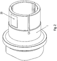
- the adapter shaft 1 has a hollow shaft area which has axially extending slots, ie axial slots.
- the axial slots are regularly spaced from one another in the circumferential direction and extend from the axially outer first end area of the adapter shaft 1 to an axial position which is arranged outside of the axial area covered by the clamping ring 4 .
- the preferred number of slots is three.
- a solid shaft is introduced into the adapter shaft 1 .
- This solid shaft is thus radially surrounded by the adapter shaft 1 .
- a first threaded pin 2 is screwed into a radially continuous threaded bore through the clamping ring 4 and presses on one arranged on the adapter shaft 1 Flattening 20.
- the adapter shaft 1 does not have a continuous recess for the first threaded pin 2.
- the flattened area 20 is embodied on the outside of the adapter shaft 1 and is aligned tangentially to the adapter shaft 1 , ie in particular perpendicularly to a radial direction which is aligned parallel to the normal direction of the flattened area 20 .
- the threaded pin 2 presses on the flattened area 20.
- the adapter shaft 1 In the axial area covered by the flattening 20, the adapter shaft 1 is cylindrical on its outer circumference, with the exception of the axial slots.
- a second threaded bore running radially through the clamping ring 4 is provided diametrically opposite the first threaded bore running through the clamping ring 4 .
- a bore 30 in the adapter shaft serves to press on the second threaded pin 3, the threaded area of which is screwed into the second radially continuous threaded bore arranged in the clamping ring.
- the bore 30 is designed as a blind hole, it overlaps with an axial slot.
- the second threaded pin 3 can thus be screwed into the second threaded bore, which runs radially through the clamping ring 4, and then presses against the bottom of the bore 30. In this way, it is secured against loss in the axial direction and in the circumferential direction.
- the axial slot preferably traverses the bore 30 centrally.
- the flattened area 20, ie that surface on which the first threaded pin 2 presses is diametrical arranged for bore 30. Since the first threaded pin 2 generates a very high contact pressure, the adapter shaft 1 can thus be shrunk without the bore 30 being displaced.
- the second threaded pin applies only a small contact pressure to the bottom surface 30 of the bore 30.
- the second threaded pin 3 has a much smaller diameter than the first threaded pin 2.
- the diameter of the second threaded bore is also much smaller, in particular at least three times smaller, than the diameter the first threaded hole.
- the adapter shaft 1 is secured in the circumferential direction.
- the first threaded pin 2 therefore has the function of pressing on the clamping ring 4 and thus causing the shaft to be clamped.
- An insertion bevel is preferably provided on the adapter shaft 1 , which causes the adapter shaft 1 to be pushed smoothly onto the clamping ring 4 .
- the clamping ring 4 is slipped onto the adapter shaft 1 in this way, the adapter shaft 1 is elastically deformed, in particular radially compressed, radially shrunk onto the shaft accommodated in the adapter shaft 1 .
- this elastic deformation can be effected with little effort.
- the adapter shaft 1 relaxes again and the shaft can thus be inserted without any particular effort.
- the non-positive connection is then established in that the threaded pin 2 presses on the flattened area 20 and the threaded pin 3 takes over the securing in the circumferential direction.
- the adapter shaft 1, the two threaded pins (2, 3) and the clamping ring 4 thus form a system for a non-positive connection.
- the inner wall of the clamping ring 4 is designed like a region of a rotating body, ie with a constant radial distance in every axial position, ie a radial distance that is independent of the circumferential position.
- the invention thus enables a clamping connection, in particular a shrink disk connection, between an adapter shaft and a shaft, in particular a solid shaft, with an integrated captive device.
Landscapes
- Engineering & Computer Science (AREA)
- General Engineering & Computer Science (AREA)
- Mechanical Engineering (AREA)
- Clamps And Clips (AREA)
Claims (10)
- Agencement destiné à relier un arbre adaptateur (1) à un arbre avec engagement positif, au moyen d'une bague de serrage (4),laquelle bague de serrage (4) est emboîtée sur l'arbre adaptateur (1),l'arbre étant emboîté dans ledit arbre adaptateur (1),sachant que ladite bague de serrage (4) est munie d'un premier perçage taraudé radialement ininterrompu dans lequel est vissé(e) une première partie vissable, en particulier un premier goujon fileté (2) exerçant une pression sur l'arbre adaptateur (1), laquelle bague de serrage (4) est dotée d'un second perçage taraudé radialement ininterrompu dans lequel est vissé(e) une seconde partie vissable, en particulier un second goujon fileté (3),ladite seconde partie vissable pénétrant, au moins partiellement, dans un renfoncement (30) de l'arbre adaptateur (1) et exerçant notamment une pression sur ledit arbre adaptateur (1),lequel arbre adaptateur (1) comporte des fentes axiales, sachant que lesdites fentes axiales sont distantes régulièrement les unes des autres dans la direction périphérique, et/ou que lesdites fentes axiales sont ininterrompues dans le sens radial et/ou débouchent au niveau d'une première extrémité axiale dudit arbre adaptateur (1), en particulier dans l'espace environnant,lesdites fentes axiales étant de réalisation ouverte en direction de ladite extrémité axiale de l'arbre adaptateur (1), c'est-à-dire qu'elles débouchent notamment dans l'espace environnant, en particulier dans l'air ambiant,caractérisé par le fait quela zone de la surface de l'arbre adaptateur (1), sur laquelle la première partie vissable (2) exerce une pression, est réalisée sous la forme d'un méplat (20), en particulier d'un méplat (20) orienté tangentiellement par rapport audit arbre adaptateur (1),sachant que la région couverte par le renfoncement (30) dans la direction périphérique inclut la région couverte, dans ladite direction périphérique, par une première fente au sein des fentes axiales,et sachant que la région couverte par ledit renfoncement, dans la direction axiale, est comprise dans la région couverte par ladite fente axiale dans ladite direction axiale.
- Agencement selon la revendication 1,
caractérisé par le fait que
le renfoncement (30) est réalisé sous la forme d'un perçage borgne, en particulier d'un perçage borgne pratiqué radialement depuis l'extérieur, notamment orienté dans le sens radial, c'est-à-dire, en particulier, non conçu pour traverser l'intégralité de la paroi de l'arbre adaptateur (1) dans le sens radial. - Agencement selon au moins l'une des revendications précédentes, caractérisé par le fait quela zone de la surface de l'arbre adaptateur (1), sur laquelle la première partie vissable (2) exerce une pression, est disposée diamétralement par rapport au renfoncement, en particulier dans la direction périphérique sur ledit arbre adaptateur (1),sachant notamment que la région, couverte axialement par ladite zone de surface, est en chevauchement avec la région couverte axialement par ledit renfoncement, ou inclut cette dernière.
- Agencement selon au moins l'une des revendications précédentes, caractérisé par le fait que
le méplat (20) est orienté perpendiculairement à une direction radiale orientée parallèlement à la direction normale dudit méplat (20). - Agencement selon au moins l'une des revendications précédentes, caractérisé par le fait que
l'arbre est emboîté dans une région de l'arbre adaptateur (1) réalisée sous la forme d'une zone d'arbre creux et est disposé, en particulier, coaxialement par rapport audit arbre adaptateur (1). - Agencement selon au moins l'une des revendications précédentes, caractérisé par le fait que
les fentes axiales sont de réalisation ouverte en direction de l'extrémité axiale de l'arbre adaptateur (1), c'est-à-dire qu'elles débouchent notamment dans l'espace environnant, en particulier dans l'air ambiant. - Agencement selon au moins l'une des revendications précédentes, caractérisé par le fait quela première partie vissable (2) est pourvue d'un diamètre au moins trois fois supérieur à celui de la seconde partie vissable (3) ;et/ou par le fait quele premier perçage taraudé est doté d'un diamètre au moins trois fois supérieur à celui du second perçage taraudé.
- Agencement selon au moins l'une des revendications précédentes, caractérisé par le fait que
l'arbre adaptateur (1) comporte un chanfrein, notamment un biseau d'insertion au niveau de sa région extrême axiale. - Agencement selon au moins l'une des revendications précédentes, caractérisé par le fait que
la bague de serrage comporte un biseau d'insertion au niveau de sa région extrême axiale. - Agencement selon au moins l'une des revendications précédentes, caractérisé par le fait que
les fentes axiales sont au nombre de trois.
Applications Claiming Priority (2)
| Application Number | Priority Date | Filing Date | Title |
|---|---|---|---|
| DE102017008438 | 2017-09-08 | ||
| PCT/EP2018/025218 WO2019048080A1 (fr) | 2017-09-08 | 2018-08-21 | Ensemble permettant de réaliser un assemblage à force entre un arbre adaptateur et un arbre au moyen d'un anneau de serrage |
Publications (2)
| Publication Number | Publication Date |
|---|---|
| EP3679262A1 EP3679262A1 (fr) | 2020-07-15 |
| EP3679262B1 true EP3679262B1 (fr) | 2022-05-04 |
Family
ID=63371649
Family Applications (1)
| Application Number | Title | Priority Date | Filing Date |
|---|---|---|---|
| EP18759551.7A Active EP3679262B1 (fr) | 2017-09-08 | 2018-08-21 | Ensemble permettant de réaliser un assemblage à force entre un arbre adaptateur et un arbre au moyen d'un anneau de serrage |
Country Status (5)
| Country | Link |
|---|---|
| US (2) | US11274706B2 (fr) |
| EP (1) | EP3679262B1 (fr) |
| CN (1) | CN111051718A (fr) |
| DE (1) | DE102018006590A1 (fr) |
| WO (1) | WO2019048080A1 (fr) |
Family Cites Families (17)
| Publication number | Priority date | Publication date | Assignee | Title |
|---|---|---|---|---|
| US2092985A (en) * | 1936-02-06 | 1937-09-14 | Ahlberg Bearing Company | Pillow block |
| US2432860A (en) * | 1945-02-01 | 1947-12-16 | Homer C Clatfelter | Adapter |
| US3276828A (en) * | 1965-11-17 | 1966-10-04 | Adamson Stephens Mfg Co | Antifriction bearings including means for coupling them to shafts |
| US3598432A (en) * | 1969-10-20 | 1971-08-10 | Designatronics Inc | Hub clamp |
| US3879046A (en) * | 1974-01-07 | 1975-04-22 | Babb Engineering Company | Rotary tool holders |
| US4074923A (en) * | 1976-12-20 | 1978-02-21 | Textron, Inc. | Locking mechanism for securing a bearing ring or the like to a shaft |
| US4896892A (en) * | 1988-12-30 | 1990-01-30 | Andrews Edward A | Tool holder bushing |
| US4958966A (en) * | 1988-12-30 | 1990-09-25 | Andrews Edward A | Tool holder bushing |
| US5601295A (en) * | 1995-12-29 | 1997-02-11 | Baker; Arthur A. | Tool holder system for industrial cutting tools |
| DE102004011361C5 (de) | 2004-03-05 | 2009-09-17 | Neugart Gmbh | Verbindung einer geschlitzten Hohlwelle oder dergleichen mit einer Welle oder einem Gegenstück |
| US7306375B2 (en) | 2005-11-02 | 2007-12-11 | Peer Bearing Company | Bearing locking collar retainer |
| US8944718B2 (en) * | 2010-09-23 | 2015-02-03 | C-Flex Bearing Co., Inc. | Clamping bushing |
| DE102011013887B4 (de) | 2011-03-07 | 2017-06-29 | Stöber Antriebstechnik GmbH & Co. KG | Klemmkupplung zur drehfesten Verbindung zweier drehender Teile, vorzugsweise Welle und Nabe |
| DE102012000537B4 (de) | 2012-01-16 | 2014-08-07 | Sew-Eurodrive Gmbh & Co Kg | Welle-Nabe-Verbindung, Adapter und Getriebemotor |
| CN105121881B (zh) * | 2013-05-23 | 2018-06-22 | 索尤若驱动有限及两合公司 | 轴毂连接结构和减速电机 |
| US9385508B2 (en) | 2013-07-26 | 2016-07-05 | Mieng Pai | Control of spatial mode distribution of a large-core laser diode system |
| CN203835994U (zh) | 2014-05-12 | 2014-09-17 | 温岭市宇龙宣机电有限公司 | 一种联轴器 |
-
2018
- 2018-08-21 US US16/645,786 patent/US11274706B2/en active Active
- 2018-08-21 WO PCT/EP2018/025218 patent/WO2019048080A1/fr not_active Ceased
- 2018-08-21 CN CN201880057287.8A patent/CN111051718A/zh active Pending
- 2018-08-21 EP EP18759551.7A patent/EP3679262B1/fr active Active
- 2018-08-21 DE DE102018006590.2A patent/DE102018006590A1/de active Pending
-
2022
- 2022-03-14 US US17/693,574 patent/US11614125B2/en active Active
Also Published As
| Publication number | Publication date |
|---|---|
| US11614125B2 (en) | 2023-03-28 |
| US20220196077A1 (en) | 2022-06-23 |
| WO2019048080A1 (fr) | 2019-03-14 |
| DE102018006590A1 (de) | 2019-03-14 |
| US11274706B2 (en) | 2022-03-15 |
| US20200271165A1 (en) | 2020-08-27 |
| EP3679262A1 (fr) | 2020-07-15 |
| CN111051718A (zh) | 2020-04-21 |
Similar Documents
| Publication | Publication Date | Title |
|---|---|---|
| EP3538792B1 (fr) | Engrenage planétaire muni d'une couronne logée dans une partie de carter | |
| EP2805078B1 (fr) | Accouplement d'arbre et moyeu, adaptateur et moteur d'entrainement | |
| EP3679261B1 (fr) | Ensemble permettant de réaliser un assemblage à force entre un arbre adaptateur et un arbre au moyen d'un anneau de serrage | |
| EP0509410B1 (fr) | Raccord pour tuyau souple | |
| DE3805702C1 (fr) | ||
| EP3679262A1 (fr) | Ensemble permettant de réaliser un assemblage à force entre un arbre adaptateur et un arbre au moyen d'un anneau de serrage | |
| DE102018004534A1 (de) | Verbindung, aufweisend eine in eine Hohlwelle zumindest teilweise eingesteckte Welle und ein auf die Hohlwelle aufgestecktes Ringteil und Planetengetriebe | |
| EP3642503B1 (fr) | Couplage comprenant un arbre au moins partiellement insere dans un arbre creux et un moyeu placé sur l'arbre creux et un engrenage planétaire | |
| EP3642501B1 (fr) | Connexion comprenant un arbre, un arbre creux et un anneau glisse sur l'arbre creux. train planetaire | |
| EP3318774A1 (fr) | Dispositif de raccordement permettant de raccorder un arbre à un composant | |
| EP3749872B1 (fr) | Procede de serrage d'une zone d'arbre creux sur un arbre au moyen d'une bague de serrage et dispositif pour la mise en oeuvre du procede | |
| EP3642502B1 (fr) | Couplage comprenant un arbre au moins partiellement insere dans un arbre creux et un moyeu placé sur l'arbre creux et un engrenage planétaire | |
| DE102019000425A1 (de) | Verfahren zum Klemmverbinden eines Hohlwellenbereichs mit einer Welle mittels eines Klemmrings und Anordnung zur Durchführung des Verfahrens | |
| EP3749874B1 (fr) | Procédé de fixation par serrage d'une zone d'arbre creux avec un arbre au moyen d'une bague de serrage et dispositif pour réaliser ce procédé | |
| EP3642504B1 (fr) | Couplage comprenant un arbre au moins partiellement insere dans un arbre creux et un moyeu placé sur l'arbre creux et un engrenage planétaire | |
| EP3642505B1 (fr) | Liaison conjointe ayant un arbre au moins partiellement inséré dans un arbre creux et une bague plaquée autour de l'arbre creux et un engrenage planétaire | |
| WO2020164801A1 (fr) | Ensemble pour le raccordement par serrage d'un arbre, boîte de vitesses à trains épicycloïdaux et procédé pour leur fabrication | |
| DE102018006591B4 (de) | Anordnung zur kraftschlüssigen Verbindung einer Adapterwelle mit einer Welle mittels eines Spannrings | |
| EP3818274A2 (fr) | Liaison avec serrage | |
| AT505131A2 (de) | Befestigungsring |
Legal Events
| Date | Code | Title | Description |
|---|---|---|---|
| STAA | Information on the status of an ep patent application or granted ep patent |
Free format text: STATUS: UNKNOWN |
|
| STAA | Information on the status of an ep patent application or granted ep patent |
Free format text: STATUS: THE INTERNATIONAL PUBLICATION HAS BEEN MADE |
|
| PUAI | Public reference made under article 153(3) epc to a published international application that has entered the european phase |
Free format text: ORIGINAL CODE: 0009012 |
|
| STAA | Information on the status of an ep patent application or granted ep patent |
Free format text: STATUS: REQUEST FOR EXAMINATION WAS MADE |
|
| 17P | Request for examination filed |
Effective date: 20200408 |
|
| AK | Designated contracting states |
Kind code of ref document: A1 Designated state(s): AL AT BE BG CH CY CZ DE DK EE ES FI FR GB GR HR HU IE IS IT LI LT LU LV MC MK MT NL NO PL PT RO RS SE SI SK SM TR |
|
| AX | Request for extension of the european patent |
Extension state: BA ME |
|
| DAV | Request for validation of the european patent (deleted) | ||
| DAX | Request for extension of the european patent (deleted) | ||
| GRAP | Despatch of communication of intention to grant a patent |
Free format text: ORIGINAL CODE: EPIDOSNIGR1 |
|
| STAA | Information on the status of an ep patent application or granted ep patent |
Free format text: STATUS: GRANT OF PATENT IS INTENDED |
|
| INTG | Intention to grant announced |
Effective date: 20211216 |
|
| GRAS | Grant fee paid |
Free format text: ORIGINAL CODE: EPIDOSNIGR3 |
|
| GRAA | (expected) grant |
Free format text: ORIGINAL CODE: 0009210 |
|
| STAA | Information on the status of an ep patent application or granted ep patent |
Free format text: STATUS: THE PATENT HAS BEEN GRANTED |
|
| AK | Designated contracting states |
Kind code of ref document: B1 Designated state(s): AL AT BE BG CH CY CZ DE DK EE ES FI FR GB GR HR HU IE IS IT LI LT LU LV MC MK MT NL NO PL PT RO RS SE SI SK SM TR |
|
| REG | Reference to a national code |
Ref country code: GB Ref legal event code: FG4D Free format text: NOT ENGLISH |
|
| REG | Reference to a national code |
Ref country code: CH Ref legal event code: EP |
|
| REG | Reference to a national code |
Ref country code: AT Ref legal event code: REF Ref document number: 1489348 Country of ref document: AT Kind code of ref document: T Effective date: 20220515 |
|
| REG | Reference to a national code |
Ref country code: IE Ref legal event code: FG4D Free format text: LANGUAGE OF EP DOCUMENT: GERMAN Ref country code: DE Ref legal event code: R096 Ref document number: 502018009593 Country of ref document: DE |
|
| REG | Reference to a national code |
Ref country code: LT Ref legal event code: MG9D |
|
| REG | Reference to a national code |
Ref country code: NL Ref legal event code: MP Effective date: 20220504 |
|
| PG25 | Lapsed in a contracting state [announced via postgrant information from national office to epo] |
Ref country code: SE Free format text: LAPSE BECAUSE OF FAILURE TO SUBMIT A TRANSLATION OF THE DESCRIPTION OR TO PAY THE FEE WITHIN THE PRESCRIBED TIME-LIMIT Effective date: 20220504 Ref country code: PT Free format text: LAPSE BECAUSE OF FAILURE TO SUBMIT A TRANSLATION OF THE DESCRIPTION OR TO PAY THE FEE WITHIN THE PRESCRIBED TIME-LIMIT Effective date: 20220905 Ref country code: NO Free format text: LAPSE BECAUSE OF FAILURE TO SUBMIT A TRANSLATION OF THE DESCRIPTION OR TO PAY THE FEE WITHIN THE PRESCRIBED TIME-LIMIT Effective date: 20220804 Ref country code: NL Free format text: LAPSE BECAUSE OF FAILURE TO SUBMIT A TRANSLATION OF THE DESCRIPTION OR TO PAY THE FEE WITHIN THE PRESCRIBED TIME-LIMIT Effective date: 20220504 Ref country code: LT Free format text: LAPSE BECAUSE OF FAILURE TO SUBMIT A TRANSLATION OF THE DESCRIPTION OR TO PAY THE FEE WITHIN THE PRESCRIBED TIME-LIMIT Effective date: 20220504 Ref country code: HR Free format text: LAPSE BECAUSE OF FAILURE TO SUBMIT A TRANSLATION OF THE DESCRIPTION OR TO PAY THE FEE WITHIN THE PRESCRIBED TIME-LIMIT Effective date: 20220504 Ref country code: GR Free format text: LAPSE BECAUSE OF FAILURE TO SUBMIT A TRANSLATION OF THE DESCRIPTION OR TO PAY THE FEE WITHIN THE PRESCRIBED TIME-LIMIT Effective date: 20220805 Ref country code: FI Free format text: LAPSE BECAUSE OF FAILURE TO SUBMIT A TRANSLATION OF THE DESCRIPTION OR TO PAY THE FEE WITHIN THE PRESCRIBED TIME-LIMIT Effective date: 20220504 Ref country code: ES Free format text: LAPSE BECAUSE OF FAILURE TO SUBMIT A TRANSLATION OF THE DESCRIPTION OR TO PAY THE FEE WITHIN THE PRESCRIBED TIME-LIMIT Effective date: 20220504 Ref country code: BG Free format text: LAPSE BECAUSE OF FAILURE TO SUBMIT A TRANSLATION OF THE DESCRIPTION OR TO PAY THE FEE WITHIN THE PRESCRIBED TIME-LIMIT Effective date: 20220804 |
|
| PG25 | Lapsed in a contracting state [announced via postgrant information from national office to epo] |
Ref country code: RS Free format text: LAPSE BECAUSE OF FAILURE TO SUBMIT A TRANSLATION OF THE DESCRIPTION OR TO PAY THE FEE WITHIN THE PRESCRIBED TIME-LIMIT Effective date: 20220504 Ref country code: PL Free format text: LAPSE BECAUSE OF FAILURE TO SUBMIT A TRANSLATION OF THE DESCRIPTION OR TO PAY THE FEE WITHIN THE PRESCRIBED TIME-LIMIT Effective date: 20220504 Ref country code: LV Free format text: LAPSE BECAUSE OF FAILURE TO SUBMIT A TRANSLATION OF THE DESCRIPTION OR TO PAY THE FEE WITHIN THE PRESCRIBED TIME-LIMIT Effective date: 20220504 Ref country code: IS Free format text: LAPSE BECAUSE OF FAILURE TO SUBMIT A TRANSLATION OF THE DESCRIPTION OR TO PAY THE FEE WITHIN THE PRESCRIBED TIME-LIMIT Effective date: 20220904 |
|
| PG25 | Lapsed in a contracting state [announced via postgrant information from national office to epo] |
Ref country code: SM Free format text: LAPSE BECAUSE OF FAILURE TO SUBMIT A TRANSLATION OF THE DESCRIPTION OR TO PAY THE FEE WITHIN THE PRESCRIBED TIME-LIMIT Effective date: 20220504 Ref country code: SK Free format text: LAPSE BECAUSE OF FAILURE TO SUBMIT A TRANSLATION OF THE DESCRIPTION OR TO PAY THE FEE WITHIN THE PRESCRIBED TIME-LIMIT Effective date: 20220504 Ref country code: RO Free format text: LAPSE BECAUSE OF FAILURE TO SUBMIT A TRANSLATION OF THE DESCRIPTION OR TO PAY THE FEE WITHIN THE PRESCRIBED TIME-LIMIT Effective date: 20220504 Ref country code: EE Free format text: LAPSE BECAUSE OF FAILURE TO SUBMIT A TRANSLATION OF THE DESCRIPTION OR TO PAY THE FEE WITHIN THE PRESCRIBED TIME-LIMIT Effective date: 20220504 Ref country code: DK Free format text: LAPSE BECAUSE OF FAILURE TO SUBMIT A TRANSLATION OF THE DESCRIPTION OR TO PAY THE FEE WITHIN THE PRESCRIBED TIME-LIMIT Effective date: 20220504 Ref country code: CZ Free format text: LAPSE BECAUSE OF FAILURE TO SUBMIT A TRANSLATION OF THE DESCRIPTION OR TO PAY THE FEE WITHIN THE PRESCRIBED TIME-LIMIT Effective date: 20220504 |
|
| REG | Reference to a national code |
Ref country code: DE Ref legal event code: R097 Ref document number: 502018009593 Country of ref document: DE |
|
| PLBE | No opposition filed within time limit |
Free format text: ORIGINAL CODE: 0009261 |
|
| STAA | Information on the status of an ep patent application or granted ep patent |
Free format text: STATUS: NO OPPOSITION FILED WITHIN TIME LIMIT |
|
| PG25 | Lapsed in a contracting state [announced via postgrant information from national office to epo] |
Ref country code: MC Free format text: LAPSE BECAUSE OF FAILURE TO SUBMIT A TRANSLATION OF THE DESCRIPTION OR TO PAY THE FEE WITHIN THE PRESCRIBED TIME-LIMIT Effective date: 20220504 Ref country code: AL Free format text: LAPSE BECAUSE OF FAILURE TO SUBMIT A TRANSLATION OF THE DESCRIPTION OR TO PAY THE FEE WITHIN THE PRESCRIBED TIME-LIMIT Effective date: 20220504 |
|
| REG | Reference to a national code |
Ref country code: CH Ref legal event code: PL |
|
| 26N | No opposition filed |
Effective date: 20230207 |
|
| GBPC | Gb: european patent ceased through non-payment of renewal fee |
Effective date: 20220821 |
|
| PG25 | Lapsed in a contracting state [announced via postgrant information from national office to epo] |
Ref country code: LU Free format text: LAPSE BECAUSE OF NON-PAYMENT OF DUE FEES Effective date: 20220821 Ref country code: LI Free format text: LAPSE BECAUSE OF NON-PAYMENT OF DUE FEES Effective date: 20220831 Ref country code: CH Free format text: LAPSE BECAUSE OF NON-PAYMENT OF DUE FEES Effective date: 20220831 |
|
| REG | Reference to a national code |
Ref country code: BE Ref legal event code: MM Effective date: 20220831 |
|
| PG25 | Lapsed in a contracting state [announced via postgrant information from national office to epo] |
Ref country code: SI Free format text: LAPSE BECAUSE OF FAILURE TO SUBMIT A TRANSLATION OF THE DESCRIPTION OR TO PAY THE FEE WITHIN THE PRESCRIBED TIME-LIMIT Effective date: 20220504 |
|
| PG25 | Lapsed in a contracting state [announced via postgrant information from national office to epo] |
Ref country code: IE Free format text: LAPSE BECAUSE OF NON-PAYMENT OF DUE FEES Effective date: 20220821 Ref country code: FR Free format text: LAPSE BECAUSE OF NON-PAYMENT OF DUE FEES Effective date: 20220831 |
|
| PG25 | Lapsed in a contracting state [announced via postgrant information from national office to epo] |
Ref country code: BE Free format text: LAPSE BECAUSE OF NON-PAYMENT OF DUE FEES Effective date: 20220831 |
|
| PG25 | Lapsed in a contracting state [announced via postgrant information from national office to epo] |
Ref country code: GB Free format text: LAPSE BECAUSE OF NON-PAYMENT OF DUE FEES Effective date: 20220821 |
|
| PG25 | Lapsed in a contracting state [announced via postgrant information from national office to epo] |
Ref country code: CY Free format text: LAPSE BECAUSE OF FAILURE TO SUBMIT A TRANSLATION OF THE DESCRIPTION OR TO PAY THE FEE WITHIN THE PRESCRIBED TIME-LIMIT Effective date: 20220504 |
|
| PG25 | Lapsed in a contracting state [announced via postgrant information from national office to epo] |
Ref country code: MK Free format text: LAPSE BECAUSE OF FAILURE TO SUBMIT A TRANSLATION OF THE DESCRIPTION OR TO PAY THE FEE WITHIN THE PRESCRIBED TIME-LIMIT Effective date: 20220504 Ref country code: HU Free format text: LAPSE BECAUSE OF FAILURE TO SUBMIT A TRANSLATION OF THE DESCRIPTION OR TO PAY THE FEE WITHIN THE PRESCRIBED TIME-LIMIT; INVALID AB INITIO Effective date: 20180821 |
|
| PG25 | Lapsed in a contracting state [announced via postgrant information from national office to epo] |
Ref country code: TR Free format text: LAPSE BECAUSE OF FAILURE TO SUBMIT A TRANSLATION OF THE DESCRIPTION OR TO PAY THE FEE WITHIN THE PRESCRIBED TIME-LIMIT Effective date: 20220504 |
|
| PG25 | Lapsed in a contracting state [announced via postgrant information from national office to epo] |
Ref country code: MT Free format text: LAPSE BECAUSE OF FAILURE TO SUBMIT A TRANSLATION OF THE DESCRIPTION OR TO PAY THE FEE WITHIN THE PRESCRIBED TIME-LIMIT Effective date: 20220504 |
|
| REG | Reference to a national code |
Ref country code: AT Ref legal event code: MM01 Ref document number: 1489348 Country of ref document: AT Kind code of ref document: T Effective date: 20230821 |
|
| PG25 | Lapsed in a contracting state [announced via postgrant information from national office to epo] |
Ref country code: AT Free format text: LAPSE BECAUSE OF NON-PAYMENT OF DUE FEES Effective date: 20230821 |
|
| PG25 | Lapsed in a contracting state [announced via postgrant information from national office to epo] |
Ref country code: AT Free format text: LAPSE BECAUSE OF NON-PAYMENT OF DUE FEES Effective date: 20230821 |
|
| PG25 | Lapsed in a contracting state [announced via postgrant information from national office to epo] |
Ref country code: BG Free format text: LAPSE BECAUSE OF FAILURE TO SUBMIT A TRANSLATION OF THE DESCRIPTION OR TO PAY THE FEE WITHIN THE PRESCRIBED TIME-LIMIT Effective date: 20220504 |
|
| PG25 | Lapsed in a contracting state [announced via postgrant information from national office to epo] |
Ref country code: BG Free format text: LAPSE BECAUSE OF FAILURE TO SUBMIT A TRANSLATION OF THE DESCRIPTION OR TO PAY THE FEE WITHIN THE PRESCRIBED TIME-LIMIT Effective date: 20220504 |
|
| PGFP | Annual fee paid to national office [announced via postgrant information from national office to epo] |
Ref country code: DE Payment date: 20250831 Year of fee payment: 8 |
|
| PGFP | Annual fee paid to national office [announced via postgrant information from national office to epo] |
Ref country code: AT Payment date: 20260410 Year of fee payment: 5 |
|
| PGFP | Annual fee paid to national office [announced via postgrant information from national office to epo] |
Ref country code: IT Payment date: 20260410 Year of fee payment: 9 |