EP3679307B1 - System zur rückgewinnung von wärme aus abwasser - Google Patents
System zur rückgewinnung von wärme aus abwasser Download PDFInfo
- Publication number
- EP3679307B1 EP3679307B1 EP18762342.6A EP18762342A EP3679307B1 EP 3679307 B1 EP3679307 B1 EP 3679307B1 EP 18762342 A EP18762342 A EP 18762342A EP 3679307 B1 EP3679307 B1 EP 3679307B1
- Authority
- EP
- European Patent Office
- Prior art keywords
- tank
- side wall
- wastewater
- transfer fluid
- heat transfer
- Prior art date
- Legal status (The legal status is an assumption and is not a legal conclusion. Google has not performed a legal analysis and makes no representation as to the accuracy of the status listed.)
- Active
Links
Images

Classifications
-
- F—MECHANICAL ENGINEERING; LIGHTING; HEATING; WEAPONS; BLASTING
- F24—HEATING; RANGES; VENTILATING
- F24H—FLUID HEATERS, e.g. WATER OR AIR HEATERS, HAVING HEAT-GENERATING MEANS, e.g. HEAT PUMPS, IN GENERAL
- F24H9/00—Details
- F24H9/0005—Details for water heaters
- F24H9/0042—Cleaning arrangements
-
- F—MECHANICAL ENGINEERING; LIGHTING; HEATING; WEAPONS; BLASTING
- F24—HEATING; RANGES; VENTILATING
- F24D—DOMESTIC- OR SPACE-HEATING SYSTEMS, e.g. CENTRAL HEATING SYSTEMS; DOMESTIC HOT-WATER SUPPLY SYSTEMS; ELEMENTS OR COMPONENTS THEREFOR
- F24D11/00—Central heating systems using heat accumulated in storage masses
- F24D11/002—Central heating systems using heat accumulated in storage masses water heating system
- F24D11/005—Central heating systems using heat accumulated in storage masses water heating system with recuperation of waste heat
-
- F—MECHANICAL ENGINEERING; LIGHTING; HEATING; WEAPONS; BLASTING
- F24—HEATING; RANGES; VENTILATING
- F24H—FLUID HEATERS, e.g. WATER OR AIR HEATERS, HAVING HEAT-GENERATING MEANS, e.g. HEAT PUMPS, IN GENERAL
- F24H9/00—Details
- F24H9/0005—Details for water heaters
- F24H9/001—Guiding means
- F24H9/0015—Guiding means in water channels
-
- F—MECHANICAL ENGINEERING; LIGHTING; HEATING; WEAPONS; BLASTING
- F28—HEAT EXCHANGE IN GENERAL
- F28D—HEAT-EXCHANGE APPARATUS, NOT PROVIDED FOR IN ANOTHER SUBCLASS, IN WHICH THE HEAT-EXCHANGE MEDIA DO NOT COME INTO DIRECT CONTACT
- F28D1/00—Heat-exchange apparatus having stationary conduit assemblies for one heat-exchange medium only, the media being in contact with different sides of the conduit wall, in which the other heat-exchange medium is a large body of fluid, e.g. domestic or motor car radiators
- F28D1/06—Heat-exchange apparatus having stationary conduit assemblies for one heat-exchange medium only, the media being in contact with different sides of the conduit wall, in which the other heat-exchange medium is a large body of fluid, e.g. domestic or motor car radiators with the heat-exchange conduits forming part of, or being attached to, the tank containing the body of fluid
-
- F—MECHANICAL ENGINEERING; LIGHTING; HEATING; WEAPONS; BLASTING
- F28—HEAT EXCHANGE IN GENERAL
- F28D—HEAT-EXCHANGE APPARATUS, NOT PROVIDED FOR IN ANOTHER SUBCLASS, IN WHICH THE HEAT-EXCHANGE MEDIA DO NOT COME INTO DIRECT CONTACT
- F28D21/00—Heat-exchange apparatus not covered by any of the groups F28D1/00 - F28D20/00
- F28D21/0001—Recuperative heat exchangers
- F28D21/0012—Recuperative heat exchangers the heat being recuperated from waste water or from condensates
-
- F—MECHANICAL ENGINEERING; LIGHTING; HEATING; WEAPONS; BLASTING
- F28—HEAT EXCHANGE IN GENERAL
- F28D—HEAT-EXCHANGE APPARATUS, NOT PROVIDED FOR IN ANOTHER SUBCLASS, IN WHICH THE HEAT-EXCHANGE MEDIA DO NOT COME INTO DIRECT CONTACT
- F28D7/00—Heat-exchange apparatus having stationary tubular conduit assemblies for both heat-exchange media, the media being in contact with different sides of a conduit wall
- F28D7/02—Heat-exchange apparatus having stationary tubular conduit assemblies for both heat-exchange media, the media being in contact with different sides of a conduit wall the conduits being helically coiled
- F28D7/026—Heat-exchange apparatus having stationary tubular conduit assemblies for both heat-exchange media, the media being in contact with different sides of a conduit wall the conduits being helically coiled the conduits of only one medium being helically coiled and formed by bent members, e.g. plates, the coils having a cylindrical configuration
-
- F—MECHANICAL ENGINEERING; LIGHTING; HEATING; WEAPONS; BLASTING
- F28—HEAT EXCHANGE IN GENERAL
- F28D—HEAT-EXCHANGE APPARATUS, NOT PROVIDED FOR IN ANOTHER SUBCLASS, IN WHICH THE HEAT-EXCHANGE MEDIA DO NOT COME INTO DIRECT CONTACT
- F28D7/00—Heat-exchange apparatus having stationary tubular conduit assemblies for both heat-exchange media, the media being in contact with different sides of a conduit wall
- F28D7/10—Heat-exchange apparatus having stationary tubular conduit assemblies for both heat-exchange media, the media being in contact with different sides of a conduit wall the conduits being arranged one within the other, e.g. concentrically
-
- F—MECHANICAL ENGINEERING; LIGHTING; HEATING; WEAPONS; BLASTING
- F28—HEAT EXCHANGE IN GENERAL
- F28D—HEAT-EXCHANGE APPARATUS, NOT PROVIDED FOR IN ANOTHER SUBCLASS, IN WHICH THE HEAT-EXCHANGE MEDIA DO NOT COME INTO DIRECT CONTACT
- F28D7/00—Heat-exchange apparatus having stationary tubular conduit assemblies for both heat-exchange media, the media being in contact with different sides of a conduit wall
- F28D7/10—Heat-exchange apparatus having stationary tubular conduit assemblies for both heat-exchange media, the media being in contact with different sides of a conduit wall the conduits being arranged one within the other, e.g. concentrically
- F28D7/106—Heat-exchange apparatus having stationary tubular conduit assemblies for both heat-exchange media, the media being in contact with different sides of a conduit wall the conduits being arranged one within the other, e.g. concentrically consisting of two coaxial conduits or modules of two coaxial conduits
-
- F—MECHANICAL ENGINEERING; LIGHTING; HEATING; WEAPONS; BLASTING
- F28—HEAT EXCHANGE IN GENERAL
- F28G—CLEANING OF INTERNAL OR EXTERNAL SURFACES OF HEAT-EXCHANGE OR HEAT-TRANSFER CONDUITS, e.g. WATER TUBES OR BOILERS
- F28G3/00—Rotary appliances
- F28G3/16—Rotary appliances using jets of fluid for removing debris
- F28G3/163—Rotary appliances using jets of fluid for removing debris from internal surfaces of heat exchange conduits
-
- E—FIXED CONSTRUCTIONS
- E03—WATER SUPPLY; SEWERAGE
- E03C—DOMESTIC PLUMBING INSTALLATIONS FOR FRESH WATER OR WASTE WATER; SINKS
- E03C1/00—Domestic plumbing installations for fresh water or waste water; Sinks
- E03C2001/005—Installations allowing recovery of heat from waste water for warming up fresh water
-
- F—MECHANICAL ENGINEERING; LIGHTING; HEATING; WEAPONS; BLASTING
- F24—HEATING; RANGES; VENTILATING
- F24D—DOMESTIC- OR SPACE-HEATING SYSTEMS, e.g. CENTRAL HEATING SYSTEMS; DOMESTIC HOT-WATER SUPPLY SYSTEMS; ELEMENTS OR COMPONENTS THEREFOR
- F24D2200/00—Heat sources or energy sources
- F24D2200/16—Waste heat
- F24D2200/20—Sewage water
-
- F—MECHANICAL ENGINEERING; LIGHTING; HEATING; WEAPONS; BLASTING
- F24—HEATING; RANGES; VENTILATING
- F24D—DOMESTIC- OR SPACE-HEATING SYSTEMS, e.g. CENTRAL HEATING SYSTEMS; DOMESTIC HOT-WATER SUPPLY SYSTEMS; ELEMENTS OR COMPONENTS THEREFOR
- F24D2220/00—Components of central heating installations excluding heat sources
- F24D2220/08—Storage tanks
-
- F—MECHANICAL ENGINEERING; LIGHTING; HEATING; WEAPONS; BLASTING
- F28—HEAT EXCHANGE IN GENERAL
- F28D—HEAT-EXCHANGE APPARATUS, NOT PROVIDED FOR IN ANOTHER SUBCLASS, IN WHICH THE HEAT-EXCHANGE MEDIA DO NOT COME INTO DIRECT CONTACT
- F28D20/00—Heat storage plants or apparatus in general; Regenerative heat-exchange apparatus not covered by groups F28D17/00 or F28D19/00
- F28D2020/0065—Details, e.g. particular heat storage tanks, auxiliary members within tanks
- F28D2020/0082—Multiple tanks arrangements, e.g. adjacent tanks, tank in tank
-
- Y—GENERAL TAGGING OF NEW TECHNOLOGICAL DEVELOPMENTS; GENERAL TAGGING OF CROSS-SECTIONAL TECHNOLOGIES SPANNING OVER SEVERAL SECTIONS OF THE IPC; TECHNICAL SUBJECTS COVERED BY FORMER USPC CROSS-REFERENCE ART COLLECTIONS [XRACs] AND DIGESTS
- Y02—TECHNOLOGIES OR APPLICATIONS FOR MITIGATION OR ADAPTATION AGAINST CLIMATE CHANGE
- Y02B—CLIMATE CHANGE MITIGATION TECHNOLOGIES RELATED TO BUILDINGS, e.g. HOUSING, HOUSE APPLIANCES OR RELATED END-USER APPLICATIONS
- Y02B30/00—Energy efficient heating, ventilation or air conditioning [HVAC]
- Y02B30/56—Heat recovery units
Definitions
- the present invention relates to the field of wastewater heat recovery systems.
- Wastewater from a building such as grey water or cooling water, contains calories that can be advantageously recovered and used, for example for heating the building itself. Recovering heat from wastewater thus makes it possible to limit the building's energy consumption.
- the building can be a building for any application, for example an office building, a residential building, a hotel or an industrial building.
- WO2010136681A2 discloses a wastewater heat recovery system, the heat recovery system comprising a wastewater retention tank and heat exchangers immersed in the wastewater inside the retention tank and provided for the circulation of a heat transfer fluid.
- FR2970071A1 discloses a grey water storage tank, the upper part of which is surrounded by a heat exchanger comprising a casing defining an annular space for the circulation of a heat transfer fluid, heat exchange fins being provided in the annular space to be immersed in the heat transfer fluid, these fins being able to be circular, spiral or straight.
- One of the aims of the invention is to propose a wastewater heat recovery system with improved efficiency.
- the invention provides a wastewater heat recovery system according to claim 1.
- the internal wastewater retention tank received in an external heat transfer fluid retention tank allows efficient heat exchange between the heat transfer fluid and the wastewater.
- the inner tank is immersed in the heat transfer fluid retained in the outer tank, and substantially the entire surface of the side wall of the outer tank can serve as a heat exchange surface between the waste water and the heat transfer fluid, which is beneficial to heat exchange.
- the conduit delimited in the inner tank forces the heat transfer fluid retained in the outer tank to circulate around the inner tank before exiting the outer tank, which avoids preferential paths of the heat transfer fluid in the outer tank and promotes heat exchange.
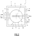
- Heat recovery system 2 illustrated on the Figures 1 And 2 is configured for heat recovery from building wastewater, such as grey water or building cooling water, by heat exchange between the wastewater and a heat transfer fluid.
- the building is intended for any application. For example, it is an office building, a residential building, a hotel or an industrial building.
- the heat recovery system 2 comprises an external tank 4 for retaining the heat transfer fluid, having a side wall 6, and an internal tank 8 for retaining the waste water, having a side wall 10, the internal tank 8 being arranged inside the external tank 4, for a heat exchange between the heat transfer fluid retained in the external tank 4 and the waste water retained in the internal tank 8, through the side wall 10 of the internal tank 8.
- the heat recovery system 2 comprises an annular retention space 12 delimited inside the external tank 4, between the side wall 6 of the external tank 4 and the side wall 10 of the internal tank 8.
- the retention space 12 surrounds the internal tank 8.
- the heat transfer fluid retained in the outer tank 4 fills the retention space 12.
- the inner tank 8 is immersed in the heat transfer fluid retained in the outer tank 4.
- the external tank 4 and the internal tank 8 extend along a longitudinal axis L.
- the longitudinal axis L is for example substantially vertical.
- the side wall 6 of the external tank 4 extends along the longitudinal axis L.
- the side wall 6 of the external tank 4 is for example cylindrical.
- the cross-section of the side wall 6 of the external tank 4 is, for example, polygonal.
- the cross-section of the side wall 6 of the external tank 4 is quadrangular, and more precisely square.
- the side wall 10 of the internal tank 8 extends along the longitudinal axis L.
- the side wall 10 of the internal tank 8 is cylindrical along the longitudinal axis L.
- the cross section of the side wall 10 of the internal tank 8 is for example circular.
- the external tank 4 has an inlet for the heat transfer fluid 14, for the entry of the heat transfer fluid into the external tank 4, and an outlet for the heat transfer fluid 16, for the exit of the heat transfer fluid from the external tank 4.
- One of the heat transfer fluid inlet 14 and the heat transfer fluid outlet 16 is located at the top of the external tank 4, the other being located at the bottom.
- the inlet for the heat transfer fluid 14 is located at the bottom of the external tank 4 and the outlet for the heat transfer fluid 16 is located at the top of the external tank 4.
- the internal tank 8 comprises a waste water inlet 18 and a waste water outlet 20.
- the waste water inlet 18 is located at the top of the internal tank 8 and the waste water outlet 20 is located at the bottom of the internal tank 8.
- the heat recovery system 2 has a waste water inlet duct 22 feeding the waste water inlet 18, and a waste water outlet duct 24 fed by the waste water outlet 20.
- the outlet duct 24 rises from the waste water outlet 20, so as to form a siphon.
- the heat recovery system 2 comprises a pipe ramp 26 arranged between the side wall 6 of the external tank 4 and the side wall 10 of the internal tank 8 so as to delimit, in the retention space 8, a circulation conduit 28 for the circulation of the heat transfer fluid, the circulation conduit 28 extending in a helix around the internal tank 8, from the inlet for the heat transfer fluid 14 to the outlet for the heat transfer fluid 16.
- the ramp 26 is arranged so that the heat transfer fluid entering the external tank 4 via the heat transfer fluid inlet 14 flows from the heat transfer fluid inlet 14 to the heat transfer fluid outlet 16 via the pipe duct 28.
- the heat transfer fluid circulates in a helix around the internal tank 8.
- the length of the path of the heat transfer fluid is increased compared to an essentially vertical path between the inlet for the heat transfer fluid 14 and the outlet for the heat transfer fluid 16. This promotes heat exchanges between the heat transfer fluid and the waste water.
- the circulation duct 28 is delimited by the ramp 26, the side wall 6 of the external tank 4 and the side wall 10 of the internal tank 8.
- the ramp 26 and the circulation conduit 28 extend in a helix around the internal tank 8, following the longitudinal axis L.
- the ramp 26 comprises several turns. Each turn of the circulation conduit 28 is delimited vertically between two consecutive turns of the ramp 26.
- the circulation conduit 28 comprises one or more turns.
- the circulation conduit 28 here comprises three turns.
- the circulation conduit 28 may comprise a single turn, two turns or more than three turns.
- the ramp 26 is here formed by a plate having an external edge 26A fixed on the side wall 6 of the external tank 4, and an internal edge 26B fixed on the side wall 10 of the internal tank 8.
- the external edge 26A of the ramp 26 is here formed of rectilinear sections to follow the side wall 8 of the external tank 4, which here has a polygonal cross section.
- the internal edge 26B of the ramp 26 is here rounded to follow the side wall 10 of the internal tank 8, which is of circular cross-section.
- the external tank 4 has a useful volume, for the retention of the heat transfer fluid, which is substantially equal to the difference between the internal volume of the external tank 4 and the external volume occupied by the internal tank 8.
- the external tank 4 is sized so that the useful volume is large in relation to the flow rate of the heat transfer fluid during operation, so that heat transfer fluid is retained in the external tank 4, being accumulated in excess in the external tank 4 compared to the flow rate of heat transfer fluid.
- the heat transfer fluid therefore remains in the external tank 4, which promotes heat exchanges with the waste water contained in the internal tank 8.
- the ratio of the useful volume of the external tank 4 to the length of the circulation conduit 28 between the inlet for the heat transfer fluid 14 and the outlet for the heat transfer fluid 16 is strictly greater than the area of the cross-section of the inlet for the heat transfer fluid 14.
- the linear flow rate of the heat transfer fluid in the circulation conduit 28 is strictly lower than that of the heat transfer fluid in the inlet for the heat transfer fluid 14.
- the slowing down of the heat transfer fluid promotes heat exchanges with the waste water contained in the external tank 4.
- the side wall 6 of the outer tank 4 and the side wall 10 of the inner tank 8 have cross sections of different shapes.
- the circulation duct 28 has a variable width on each turn of the circulation duct 28.
- the widest areas of the circulation duct 28 define areas of slowing down the flow rate of the heat transfer fluid and of storage of heat transfer fluid.
- the external tank 4 of polygonal, and in particular square, cross-section offers heat transfer fluid storage areas in the corners of the external tank 4, where the heat transfer fluid circulates at low speed.
- the external tank 4 of polygonal cross-section, and in particular square facilitates the integration of the heat recovery system 2 into a more complex assembly, while preserving the compactness of the heat recovery system 2.
- the inner tank 8 has a bottom 30 which is inclined towards a drain opening 32.
- the bottom 30 of the inner tank 8 is here conical, and converges from the lower end of the side wall 10 of the inner tank 8 towards the drain opening 32.
- the heat recovery system 2 includes a drain valve 34 arranged to control the flow of waste water through the drain opening 32.
- the outlet for waste water 20 is here formed in the bottom 30 of the internal tank 8, near the lower end of the side wall 10 of the internal tank 8.
- the external tank 4 here has a flat and substantially horizontal bottom 36.
- the heat recovery system 2 comprises a cleaning device 38 configured for cleaning the interior of the internal tank 8.
- the cleaning device 38 comprises for example one or more cleaning nozzles 40, each cleaning nozzle 40 being arranged to spray a cleaning fluid inside the internal tank 8, and a supply conduit 42 configured to supply each cleaning nozzle 40 with cleaning fluid from a source (not shown).
- Each cleaning nozzle 40 is permanently mounted inside the internal tank 8 to be able to carry out cleaning operations during use without having to open the internal tank 8.
- the cleaning device 38 comprises, for example, several cleaning nozzles 40 arranged along the supply duct 42. There are three cleaning nozzles 40 here.
- the heat recovery system 2 comprises a common cover 44 jointly closing the external tank 4 and the internal tank 8 received inside the external tank 4.
- the internal tank 8 has a large volume compared to the flow rate of the waste water, so that the waste water is retained in the internal tank 8.
- the heat transfer fluid circulates in the outer tank 4 by flowing from the heat transfer fluid inlet to the heat transfer fluid outlet along the conduit.
- the conduit 28 extending in a helix around the inner tank 8 forces the heat transfer fluid to circulate along the side wall of the inner tank 8 for better heat exchange.
- the external tank 4 is for example fluidically connected to a heat transfer fluid circuit for the circulation of the heat transfer fluid, the heat transfer fluid circuit further comprising at least one heat exchanger for a heat exchange between the heat transfer fluid and another fluid.
- the heat exchanger is thermally coupled to a heat pump circuit, the heat transfer fluid, and thus indirectly the waste water, being used as a heat source for the heat pump.
- Such a heat pump can be used, for example, for heating the building whose waste water feeds the heat recovery system 2.
- Heat recovery system 2 enables efficient heat recovery from waste water using a heat transfer fluid.
- the circulation duct forces the heat transfer fluid to rotate around the internal tank 8 to improve heat exchange.
- the circulation duct defined between the side walls of the internal tank 8 and the external tank 4 may have a cross section allowing slow circulation of the heat transfer fluid around the internal tank 8, conducive to efficient heat exchanges.
- Heat recovery system 2 can be manufactured easily and at low cost.
- the internal wastewater retention tank 8 defines a buffer tank in which the wastewater is retained. It therefore resides there for a certain time, which is favorable to the recovery of the heat contained in this wastewater, unlike a heat recovery system formed by a conduit in which the wastewater circulates without being retained.
- the heat recovery system 2 is configured so that the waste water circulates in the internal tank 8 by siphon effect.
- a quantity of waste water located at the bottom of the internal tank 8 exits the internal tank 8 from the bottom when a corresponding quantity enters the internal tank 8 from the top of the internal tank 8. This is achieved by the outlet conduit 24 rising from the outlet 20 to form a siphon.
- the heat recovery system 2 is configured so that the hottest waste water remains at the top and the coldest water remains at the bottom of the internal tank 8.
- the hottest wastewater is retained at the top of the internal tank 8 while the coldest wastewater is evacuated more quickly from the bottom of the internal tank 8, in particular due to the circulation by siphon effect. This promotes heat recovery.
- the heat transfer fluid circulating in the external tank 4 is also retained in this external tank 4 which promotes the recovery of heat from the waste water.
- the heat transfer fluid circulating in a heat transfer fluid circuit having a heat exchanger for heat exchange with another fluid is not in contact with the waste water or with the other fluid.
- the wastewater recovery system 2 limits the risks of pollution. It is of sanitary design.
- the internal tank 8 equipped with a drain valve 34 and a cleaning device 38 is easy to maintain.
Landscapes
- Engineering & Computer Science (AREA)
- Mechanical Engineering (AREA)
- General Engineering & Computer Science (AREA)
- Physics & Mathematics (AREA)
- Thermal Sciences (AREA)
- Chemical & Material Sciences (AREA)
- Combustion & Propulsion (AREA)
- Heat-Exchange Devices With Radiators And Conduit Assemblies (AREA)
Claims (11)
- Wärmerückgewinnungssystem (2) aus Brauchwasser durch Wärmeaustausch zwischen dem Brauchwasser und einem Wärmeträgerfluid, das Wärmerückgewinnungssystem (2) umfassend:- einen äußeren Behälter (4) zum Enthalten des Wärmeträgerfluids, wobei der äußere Behälter (4) eine Seitenwand (6) besitzt, wobei der äußere Behälter (4) einen Einlass für das Wärmeträgerfluid (14) und einen Auslass für das Wärmeträgerfluid (16) besitzt, wovon sich einer an einer Oberseite des äußeren Behälters (4) befindet und sich der andere an einer Unterseite des äußeren Behälters (4) befindet,- einen inneren Behälter (8) zum Enthalten des Brauchwassers, wobei der innere Behälter (8) eine Seitenwand (10) besitzt, wobei der innere Behälter (8) für einen Wärmeaustausch zwischen dem Wärmeträger und dem Brauchwasser über die Seitenwand (10) des inneren Behälters (8) im Innern des äußeren Behälters (4) angeordnet ist, wobei ein ringförmiger Rückhalteraum zwischen der Seitenwand (6) des äußeren Behälters (4) und der Seitenwand (10) des inneren Behälters (8) begrenzt ist, und- eine Kanalrampe (26), die zwischen der Seitenwand (6) des äußeren Behälters (4) und der Seitenwand (10) des inneren Behälters (8) angeordnet ist, um in dem Rückhalteraum eine Zirkulationsleitung (28) zu begrenzen, die sich für die Zirkulation des Wärmeträgerfluids von dem Einlass für das Wärmeträgerfluid (14) zu dem Auslass für das Wärmeträgerfluid (16) spiralförmig um den inneren Behälter (8) erstrecktwobei der innere Behälter (8) einen Einlass für das Brauchwasser (18) und einen Auslass für das Brauchwasser (20), der sich an einer Unterseite des inneren Behälters (8) befindet, aufweist, wobei das Wärmerückgewinnungssystem eine Einlassleitung (22) für das Brauchwasser, die den Einlass für das Brauchwasser (18) speist, und eine Auslassleitung (24) für das Brauchwasser aufweist, die von dem Auslass für das Brauchwasser (20) gespeist wird, wobei die Auslassleitung (24) von dem Auslass für das Brauchwasser (20) aufwärts verläuft, um einen Siphon zu bilden,
wobei das System dadurch gekennzeichnet ist, dass sich der Einlass für das Brauchwasser (18) an einer Oberseite des inneren Behälters (8) befindet. - Wärmerückgewinnungssystem nach Anspruch 1, wobei die Seitenwand (10) des inneren Behälters (8) von kreisförmigem Querschnitt ist.
- Wärmerückgewinnungssystem nach Anspruch 1 oder Anspruch 2, wobei der innere Behälter (8) einen Boden (30) besitzt, der zu einer Entleerungsöffnung (32) hin geneigt ist.
- Wärmerückgewinnungssystem nach Anspruch 3, wobei der Boden (30) konisch ist und von einem unteren Ende der Seitenwand (10) des inneren Behälters (8) zu der Entleerungsöffnung (32) hin konvergiert.
- Wärmerückgewinnungssystem nach Anspruch 3 oder 4, wobei der Auslass für das Brauchwasser (20) in dem Boden (30) des inneren Behälters (8) in der Nähe eines unteren Endes der Seitenwand (10) des inneren Behälters (8) gebildet ist.
- Wärmerückgewinnungssystem nach einem der vorherigen Ansprüche, umfassend eine Reinigungsvorrichtung (38), umfassend mindestens eine Reinigungsdüse (40) zum Sprühen eines Reinigungsfluids im Inneren des inneren Behälters (8).
- Wärmerückgewinnungssystem nach einem der vorherigen Ansprüche, umfassend ein Entleerungsventil (34), das angeordnet ist, um die Entleerung des inneren Behälters (8) zu steuern.
- Wärmerückgewinnungssystem nach einem der Ansprüche 1 bis 5, umfassend ein Entleerungsventil (34), das angeordnet ist, um den Durchfluss von Brauchwasser durch die Entleerungsöffnung (32) zu steuern.
- Wärmerückgewinnungssystem nach einem der vorherigen Ansprüche, wobei die Seitenwand (6) des äußeren Behälters (4) einen polygonalen Querschnitt besitzt.
- Wärmerückgewinnungssystem nach einem der vorherigen Ansprüche, wobei die Seitenwand (6) des äußeren Behälters (4) einen viereckigen Querschnitt besitzt.
- Wärmerückgewinnungssystem nach einem der vorherigen Ansprüche, wobei die Seitenwand (10) des inneren Behälters (8) und die Seitenwand (6) des äußeren Behälters (4) Querschnitte unterschiedlicher Formen aufweisen.
Applications Claiming Priority (2)
| Application Number | Priority Date | Filing Date | Title |
|---|---|---|---|
| FR1758320A FR3071044B1 (fr) | 2017-09-08 | 2017-09-08 | Systeme de recuperation de chaleur des eaux usees |
| PCT/EP2018/074229 WO2019048651A1 (fr) | 2017-09-08 | 2018-09-07 | Système de récupération de chaleur des eaux usées |
Publications (3)
| Publication Number | Publication Date |
|---|---|
| EP3679307A1 EP3679307A1 (de) | 2020-07-15 |
| EP3679307B1 true EP3679307B1 (de) | 2024-11-06 |
| EP3679307B8 EP3679307B8 (de) | 2024-12-11 |
Family
ID=60923607
Family Applications (1)
| Application Number | Title | Priority Date | Filing Date |
|---|---|---|---|
| EP18762342.6A Active EP3679307B8 (de) | 2017-09-08 | 2018-09-07 | System zur rückgewinnung von wärme aus abwasser |
Country Status (3)
| Country | Link |
|---|---|
| EP (1) | EP3679307B8 (de) |
| FR (1) | FR3071044B1 (de) |
| WO (1) | WO2019048651A1 (de) |
Families Citing this family (1)
| Publication number | Priority date | Publication date | Assignee | Title |
|---|---|---|---|---|
| JP7514779B2 (ja) * | 2021-02-15 | 2024-07-11 | 三菱重工業株式会社 | 熱交換器 |
Family Cites Families (4)
| Publication number | Priority date | Publication date | Assignee | Title |
|---|---|---|---|---|
| FR2946133B1 (fr) | 2009-05-26 | 2011-07-15 | Alain Moure | Dispositif de recuperation de chaleur a partir d'eaux usees, systeme thermique comprenant un tel dispositif et procede. |
| FR2970071B1 (fr) * | 2011-01-05 | 2017-05-12 | Lyonnaise Eaux France | Dispositif de recuperation de la chaleur sur les eaux grises |
| GB2510794A (en) * | 2012-07-25 | 2014-08-20 | Bohdan Majchrowski | Heat recovery systems |
| FR3038974A1 (fr) * | 2015-07-17 | 2017-01-20 | Patrick Berenguer | Systeme de recuperation de calories sur des eaux usees, procede de mise en oeuvre |
-
2017
- 2017-09-08 FR FR1758320A patent/FR3071044B1/fr active Active
-
2018
- 2018-09-07 EP EP18762342.6A patent/EP3679307B8/de active Active
- 2018-09-07 WO PCT/EP2018/074229 patent/WO2019048651A1/fr not_active Ceased
Also Published As
| Publication number | Publication date |
|---|---|
| FR3071044A1 (fr) | 2019-03-15 |
| EP3679307A1 (de) | 2020-07-15 |
| FR3071044B1 (fr) | 2020-03-13 |
| EP3679307B8 (de) | 2024-12-11 |
| WO2019048651A1 (fr) | 2019-03-14 |
Similar Documents
| Publication | Publication Date | Title |
|---|---|---|
| EP2435762B1 (de) | Vorrichtung zur wärmerückgewinnung aus abwasser, thermisches system mit einer derartigen vorrichtung und verfahren | |
| WO2010026352A2 (fr) | Système de chauffage avec récupération de chaleur des eaux usées optimisée | |
| BE1014488A5 (fr) | Bouche de fourniture d'air. | |
| FR2983566A1 (fr) | Brise-jet dispose a l'entree d'eau dans un reservoir de stockage d'eau chaude. | |
| EP3833467B1 (de) | Vorrichtung und verfahren zum inkontaktbringen eines gasstromes mit einem flüssigkeitsstrom, und verwendung der vorrichtung | |
| FR2525291A1 (fr) | Procede et installation pour elever un liquide d'un reservoir jusqu'a une cuve surelevee | |
| FR2977016A1 (fr) | Systeme d'energie thermique et procede pour le faire fonctionner | |
| EP3679307A1 (de) | System zur rückgewinnung von wärme aus abwasser | |
| FR2680193A1 (fr) | Toilettes economes en eau. | |
| EP2080975A1 (de) | Vorrichtung zum Wärmeaustausch zwischen Flüssigkeiten, die zwei verschiedenen Kreisläufen angehören | |
| FR3106878A1 (fr) | Echangeur de chaleur notamment pour bac à douche | |
| FR2970071A1 (fr) | Dispositif de recuperation de la chaleur sur les eaux grises | |
| FR2616883A1 (fr) | Bac d'epuration d'eau de generateur de vapeur | |
| EP1704289A1 (de) | Flüssigkeitsevakuierungsvorrichtung und entsprechende flüssigkeitsführungsvorrichtung | |
| FR2986861A1 (fr) | Accumulateur combine pour eau sanitaire | |
| FR2835010A1 (fr) | Procede de circulation et nettoyage de l'eau de piscines, implantation d'un systeme pour la mise en oeuvre du procede et multiplicateur de debit adapte | |
| FR3052540B1 (fr) | Systeme de recuperation de chaleur des eaux usees ameliore | |
| FR2850122A1 (fr) | Dispositif d'extraction de l'eau presente dans l'air par condensation | |
| EP1152659B1 (de) | Geräte zum ködern für jeden angeltypen und mit jeder köderart, am meer, am see, am fluss, am ufer oder vom boot aus | |
| EP0364381A1 (de) | Vorrichtung zur Klimatisierung von Innenluft | |
| FR2953510A1 (fr) | Purificateur d'eau saumatre a distillation solaire | |
| FR3148468A1 (fr) | Récupérateur de calories des eaux usées | |
| FR2713323A1 (fr) | Aéro-réfrigérants atmosphériques à ruissellement. | |
| FR3030028A1 (fr) | Dispositif de chauffage d'un flux d'eau par echange thermique avec un flux d'eau de drainage | |
| FR2942027A1 (fr) | Chauffage solaire |
Legal Events
| Date | Code | Title | Description |
|---|---|---|---|
| STAA | Information on the status of an ep patent application or granted ep patent |
Free format text: STATUS: UNKNOWN |
|
| STAA | Information on the status of an ep patent application or granted ep patent |
Free format text: STATUS: THE INTERNATIONAL PUBLICATION HAS BEEN MADE |
|
| PUAI | Public reference made under article 153(3) epc to a published international application that has entered the european phase |
Free format text: ORIGINAL CODE: 0009012 |
|
| STAA | Information on the status of an ep patent application or granted ep patent |
Free format text: STATUS: REQUEST FOR EXAMINATION WAS MADE |
|
| 17P | Request for examination filed |
Effective date: 20200408 |
|
| AK | Designated contracting states |
Kind code of ref document: A1 Designated state(s): AL AT BE BG CH CY CZ DE DK EE ES FI FR GB GR HR HU IE IS IT LI LT LU LV MC MK MT NL NO PL PT RO RS SE SI SK SM TR |
|
| AX | Request for extension of the european patent |
Extension state: BA ME |
|
| DAV | Request for validation of the european patent (deleted) | ||
| DAX | Request for extension of the european patent (deleted) | ||
| RIN1 | Information on inventor provided before grant (corrected) |
Inventor name: MOURE, ALAIN |
|
| STAA | Information on the status of an ep patent application or granted ep patent |
Free format text: STATUS: EXAMINATION IS IN PROGRESS |
|
| 17Q | First examination report despatched |
Effective date: 20221206 |
|
| GRAP | Despatch of communication of intention to grant a patent |
Free format text: ORIGINAL CODE: EPIDOSNIGR1 |
|
| STAA | Information on the status of an ep patent application or granted ep patent |
Free format text: STATUS: GRANT OF PATENT IS INTENDED |
|
| INTG | Intention to grant announced |
Effective date: 20240527 |
|
| GRAS | Grant fee paid |
Free format text: ORIGINAL CODE: EPIDOSNIGR3 |
|
| GRAA | (expected) grant |
Free format text: ORIGINAL CODE: 0009210 |
|
| STAA | Information on the status of an ep patent application or granted ep patent |
Free format text: STATUS: THE PATENT HAS BEEN GRANTED |
|
| AK | Designated contracting states |
Kind code of ref document: B1 Designated state(s): AL AT BE BG CH CY CZ DE DK EE ES FI FR GB GR HR HU IE IS IT LI LT LU LV MC MK MT NL NO PL PT RO RS SE SI SK SM TR |
|
| REG | Reference to a national code |
Ref country code: GB Ref legal event code: FG4D Free format text: NOT ENGLISH |
|
| REG | Reference to a national code |
Ref country code: DE Ref legal event code: R081 Ref document number: 602018076281 Country of ref document: DE Owner name: BIOFLUIDES, FR Free format text: FORMER OWNER: BIOFLUIDES, SAINT-FARGEAU-PONTHIERRY, FR |
|
| REG | Reference to a national code |
Ref country code: CH Ref legal event code: PK Free format text: RECTIFICATION B8 Ref country code: CH Ref legal event code: EP |
|
| REG | Reference to a national code |
Ref country code: DE Ref legal event code: R096 Ref document number: 602018076281 Country of ref document: DE |
|
| RAP2 | Party data changed (patent owner data changed or rights of a patent transferred) |
Owner name: BIOFLUIDES |
|
| REG | Reference to a national code |
Ref country code: IE Ref legal event code: FG4D Free format text: LANGUAGE OF EP DOCUMENT: FRENCH |
|
| REG | Reference to a national code |
Ref country code: LT Ref legal event code: MG9D |
|
| REG | Reference to a national code |
Ref country code: NL Ref legal event code: MP Effective date: 20241106 |
|
| PG25 | Lapsed in a contracting state [announced via postgrant information from national office to epo] |
Ref country code: IS Free format text: LAPSE BECAUSE OF FAILURE TO SUBMIT A TRANSLATION OF THE DESCRIPTION OR TO PAY THE FEE WITHIN THE PRESCRIBED TIME-LIMIT Effective date: 20250306 Ref country code: PT Free format text: LAPSE BECAUSE OF FAILURE TO SUBMIT A TRANSLATION OF THE DESCRIPTION OR TO PAY THE FEE WITHIN THE PRESCRIBED TIME-LIMIT Effective date: 20250306 Ref country code: HR Free format text: LAPSE BECAUSE OF FAILURE TO SUBMIT A TRANSLATION OF THE DESCRIPTION OR TO PAY THE FEE WITHIN THE PRESCRIBED TIME-LIMIT Effective date: 20241106 |
|
| PG25 | Lapsed in a contracting state [announced via postgrant information from national office to epo] |
Ref country code: FI Free format text: LAPSE BECAUSE OF FAILURE TO SUBMIT A TRANSLATION OF THE DESCRIPTION OR TO PAY THE FEE WITHIN THE PRESCRIBED TIME-LIMIT Effective date: 20241106 Ref country code: NL Free format text: LAPSE BECAUSE OF FAILURE TO SUBMIT A TRANSLATION OF THE DESCRIPTION OR TO PAY THE FEE WITHIN THE PRESCRIBED TIME-LIMIT Effective date: 20241106 |
|
| REG | Reference to a national code |
Ref country code: AT Ref legal event code: MK05 Ref document number: 1739721 Country of ref document: AT Kind code of ref document: T Effective date: 20241106 |
|
| PG25 | Lapsed in a contracting state [announced via postgrant information from national office to epo] |
Ref country code: BG Free format text: LAPSE BECAUSE OF FAILURE TO SUBMIT A TRANSLATION OF THE DESCRIPTION OR TO PAY THE FEE WITHIN THE PRESCRIBED TIME-LIMIT Effective date: 20241106 |
|
| PG25 | Lapsed in a contracting state [announced via postgrant information from national office to epo] |
Ref country code: ES Free format text: LAPSE BECAUSE OF FAILURE TO SUBMIT A TRANSLATION OF THE DESCRIPTION OR TO PAY THE FEE WITHIN THE PRESCRIBED TIME-LIMIT Effective date: 20241106 |
|
| PG25 | Lapsed in a contracting state [announced via postgrant information from national office to epo] |
Ref country code: NO Free format text: LAPSE BECAUSE OF FAILURE TO SUBMIT A TRANSLATION OF THE DESCRIPTION OR TO PAY THE FEE WITHIN THE PRESCRIBED TIME-LIMIT Effective date: 20250206 |
|
| PG25 | Lapsed in a contracting state [announced via postgrant information from national office to epo] |
Ref country code: LV Free format text: LAPSE BECAUSE OF FAILURE TO SUBMIT A TRANSLATION OF THE DESCRIPTION OR TO PAY THE FEE WITHIN THE PRESCRIBED TIME-LIMIT Effective date: 20241106 Ref country code: GR Free format text: LAPSE BECAUSE OF FAILURE TO SUBMIT A TRANSLATION OF THE DESCRIPTION OR TO PAY THE FEE WITHIN THE PRESCRIBED TIME-LIMIT Effective date: 20250207 Ref country code: AT Free format text: LAPSE BECAUSE OF FAILURE TO SUBMIT A TRANSLATION OF THE DESCRIPTION OR TO PAY THE FEE WITHIN THE PRESCRIBED TIME-LIMIT Effective date: 20241106 |
|
| PG25 | Lapsed in a contracting state [announced via postgrant information from national office to epo] |
Ref country code: PL Free format text: LAPSE BECAUSE OF FAILURE TO SUBMIT A TRANSLATION OF THE DESCRIPTION OR TO PAY THE FEE WITHIN THE PRESCRIBED TIME-LIMIT Effective date: 20241106 |
|
| PG25 | Lapsed in a contracting state [announced via postgrant information from national office to epo] |
Ref country code: RS Free format text: LAPSE BECAUSE OF FAILURE TO SUBMIT A TRANSLATION OF THE DESCRIPTION OR TO PAY THE FEE WITHIN THE PRESCRIBED TIME-LIMIT Effective date: 20250206 |
|
| PG25 | Lapsed in a contracting state [announced via postgrant information from national office to epo] |
Ref country code: SM Free format text: LAPSE BECAUSE OF FAILURE TO SUBMIT A TRANSLATION OF THE DESCRIPTION OR TO PAY THE FEE WITHIN THE PRESCRIBED TIME-LIMIT Effective date: 20241106 |
|
| PG25 | Lapsed in a contracting state [announced via postgrant information from national office to epo] |
Ref country code: DK Free format text: LAPSE BECAUSE OF FAILURE TO SUBMIT A TRANSLATION OF THE DESCRIPTION OR TO PAY THE FEE WITHIN THE PRESCRIBED TIME-LIMIT Effective date: 20241106 |
|
| PG25 | Lapsed in a contracting state [announced via postgrant information from national office to epo] |
Ref country code: RO Free format text: LAPSE BECAUSE OF FAILURE TO SUBMIT A TRANSLATION OF THE DESCRIPTION OR TO PAY THE FEE WITHIN THE PRESCRIBED TIME-LIMIT Effective date: 20241106 |
|
| PG25 | Lapsed in a contracting state [announced via postgrant information from national office to epo] |
Ref country code: SK Free format text: LAPSE BECAUSE OF FAILURE TO SUBMIT A TRANSLATION OF THE DESCRIPTION OR TO PAY THE FEE WITHIN THE PRESCRIBED TIME-LIMIT Effective date: 20241106 |
|
| PG25 | Lapsed in a contracting state [announced via postgrant information from national office to epo] |
Ref country code: CZ Free format text: LAPSE BECAUSE OF FAILURE TO SUBMIT A TRANSLATION OF THE DESCRIPTION OR TO PAY THE FEE WITHIN THE PRESCRIBED TIME-LIMIT Effective date: 20241106 |
|
| PG25 | Lapsed in a contracting state [announced via postgrant information from national office to epo] |
Ref country code: IT Free format text: LAPSE BECAUSE OF FAILURE TO SUBMIT A TRANSLATION OF THE DESCRIPTION OR TO PAY THE FEE WITHIN THE PRESCRIBED TIME-LIMIT Effective date: 20241106 |
|
| REG | Reference to a national code |
Ref country code: DE Ref legal event code: R097 Ref document number: 602018076281 Country of ref document: DE |
|
| PG25 | Lapsed in a contracting state [announced via postgrant information from national office to epo] |
Ref country code: SE Free format text: LAPSE BECAUSE OF FAILURE TO SUBMIT A TRANSLATION OF THE DESCRIPTION OR TO PAY THE FEE WITHIN THE PRESCRIBED TIME-LIMIT Effective date: 20241106 |
|
| PLBE | No opposition filed within time limit |
Free format text: ORIGINAL CODE: 0009261 |
|
| STAA | Information on the status of an ep patent application or granted ep patent |
Free format text: STATUS: NO OPPOSITION FILED WITHIN TIME LIMIT |
|
| 26N | No opposition filed |
Effective date: 20250807 |
|
| PGFP | Annual fee paid to national office [announced via postgrant information from national office to epo] |
Ref country code: LU Payment date: 20250929 Year of fee payment: 8 |
|
| PGFP | Annual fee paid to national office [announced via postgrant information from national office to epo] |
Ref country code: BE Payment date: 20250929 Year of fee payment: 8 |
|
| PGFP | Annual fee paid to national office [announced via postgrant information from national office to epo] |
Ref country code: FR Payment date: 20250929 Year of fee payment: 8 |
|
| REG | Reference to a national code |
Ref country code: CH Ref legal event code: U11 Free format text: ST27 STATUS EVENT CODE: U-0-0-U10-U11 (AS PROVIDED BY THE NATIONAL OFFICE) Effective date: 20251031 |
|
| REG | Reference to a national code |
Ref country code: CH Ref legal event code: R18 Free format text: ST27 STATUS EVENT CODE: U-0-0-R10-R18 (AS PROVIDED BY THE NATIONAL OFFICE) Effective date: 20260106 |
|
| PGFP | Annual fee paid to national office [announced via postgrant information from national office to epo] |
Ref country code: DE Payment date: 20251015 Year of fee payment: 8 |
|
| PGFP | Annual fee paid to national office [announced via postgrant information from national office to epo] |
Ref country code: CH Payment date: 20251031 Year of fee payment: 8 |