EP3679310B1 - System und verfahren zur gewinnung von neon und anderen nichtkondensierbaren gasen, sowie von xenon und krypton aus einer luftzerlegungsanlage - Google Patents
System und verfahren zur gewinnung von neon und anderen nichtkondensierbaren gasen, sowie von xenon und krypton aus einer luftzerlegungsanlage Download PDFInfo
- Publication number
- EP3679310B1 EP3679310B1 EP18743231.5A EP18743231A EP3679310B1 EP 3679310 B1 EP3679310 B1 EP 3679310B1 EP 18743231 A EP18743231 A EP 18743231A EP 3679310 B1 EP3679310 B1 EP 3679310B1
- Authority
- EP
- European Patent Office
- Prior art keywords
- stream
- column
- liquid nitrogen
- separation unit
- air separation
- Prior art date
- Legal status (The legal status is an assumption and is not a legal conclusion. Google has not performed a legal analysis and makes no representation as to the accuracy of the status listed.)
- Active
Links
Images






Classifications
-
- F—MECHANICAL ENGINEERING; LIGHTING; HEATING; WEAPONS; BLASTING
- F25—REFRIGERATION OR COOLING; COMBINED HEATING AND REFRIGERATION SYSTEMS; HEAT PUMP SYSTEMS; MANUFACTURE OR STORAGE OF ICE; LIQUEFACTION SOLIDIFICATION OF GASES
- F25J—LIQUEFACTION, SOLIDIFICATION OR SEPARATION OF GASES OR GASEOUS OR LIQUEFIED GASEOUS MIXTURES BY PRESSURE AND COLD TREATMENT OR BY BRINGING THEM INTO THE SUPERCRITICAL STATE
- F25J3/00—Processes or apparatus for separating the constituents of gaseous or liquefied gaseous mixtures involving the use of liquefaction or solidification
- F25J3/02—Processes or apparatus for separating the constituents of gaseous or liquefied gaseous mixtures involving the use of liquefaction or solidification by rectification, i.e. by continuous interchange of heat and material between a vapour stream and a liquid stream
- F25J3/04—Processes or apparatus for separating the constituents of gaseous or liquefied gaseous mixtures involving the use of liquefaction or solidification by rectification, i.e. by continuous interchange of heat and material between a vapour stream and a liquid stream for air
- F25J3/04642—Recovering noble gases from air
- F25J3/04745—Krypton and/or Xenon
-
- F—MECHANICAL ENGINEERING; LIGHTING; HEATING; WEAPONS; BLASTING
- F25—REFRIGERATION OR COOLING; COMBINED HEATING AND REFRIGERATION SYSTEMS; HEAT PUMP SYSTEMS; MANUFACTURE OR STORAGE OF ICE; LIQUEFACTION SOLIDIFICATION OF GASES
- F25J—LIQUEFACTION, SOLIDIFICATION OR SEPARATION OF GASES OR GASEOUS OR LIQUEFIED GASEOUS MIXTURES BY PRESSURE AND COLD TREATMENT OR BY BRINGING THEM INTO THE SUPERCRITICAL STATE
- F25J3/00—Processes or apparatus for separating the constituents of gaseous or liquefied gaseous mixtures involving the use of liquefaction or solidification
- F25J3/02—Processes or apparatus for separating the constituents of gaseous or liquefied gaseous mixtures involving the use of liquefaction or solidification by rectification, i.e. by continuous interchange of heat and material between a vapour stream and a liquid stream
- F25J3/04—Processes or apparatus for separating the constituents of gaseous or liquefied gaseous mixtures involving the use of liquefaction or solidification by rectification, i.e. by continuous interchange of heat and material between a vapour stream and a liquid stream for air
- F25J3/04006—Providing pressurised feed air or process streams within or from the air fractionation unit
- F25J3/04048—Providing pressurised feed air or process streams within or from the air fractionation unit by compression of cold gaseous streams, e.g. intermediate or oxygen enriched (waste) streams
- F25J3/0406—Providing pressurised feed air or process streams within or from the air fractionation unit by compression of cold gaseous streams, e.g. intermediate or oxygen enriched (waste) streams of nitrogen
-
- F—MECHANICAL ENGINEERING; LIGHTING; HEATING; WEAPONS; BLASTING
- F25—REFRIGERATION OR COOLING; COMBINED HEATING AND REFRIGERATION SYSTEMS; HEAT PUMP SYSTEMS; MANUFACTURE OR STORAGE OF ICE; LIQUEFACTION SOLIDIFICATION OF GASES
- F25J—LIQUEFACTION, SOLIDIFICATION OR SEPARATION OF GASES OR GASEOUS OR LIQUEFIED GASEOUS MIXTURES BY PRESSURE AND COLD TREATMENT OR BY BRINGING THEM INTO THE SUPERCRITICAL STATE
- F25J3/00—Processes or apparatus for separating the constituents of gaseous or liquefied gaseous mixtures involving the use of liquefaction or solidification
- F25J3/02—Processes or apparatus for separating the constituents of gaseous or liquefied gaseous mixtures involving the use of liquefaction or solidification by rectification, i.e. by continuous interchange of heat and material between a vapour stream and a liquid stream
- F25J3/04—Processes or apparatus for separating the constituents of gaseous or liquefied gaseous mixtures involving the use of liquefaction or solidification by rectification, i.e. by continuous interchange of heat and material between a vapour stream and a liquid stream for air
- F25J3/04006—Providing pressurised feed air or process streams within or from the air fractionation unit
- F25J3/04078—Providing pressurised feed air or process streams within or from the air fractionation unit providing pressurized products by liquid compression and vaporisation with cold recovery, i.e. so-called internal compression
- F25J3/0409—Providing pressurised feed air or process streams within or from the air fractionation unit providing pressurized products by liquid compression and vaporisation with cold recovery, i.e. so-called internal compression of oxygen
-
- F—MECHANICAL ENGINEERING; LIGHTING; HEATING; WEAPONS; BLASTING
- F25—REFRIGERATION OR COOLING; COMBINED HEATING AND REFRIGERATION SYSTEMS; HEAT PUMP SYSTEMS; MANUFACTURE OR STORAGE OF ICE; LIQUEFACTION SOLIDIFICATION OF GASES
- F25J—LIQUEFACTION, SOLIDIFICATION OR SEPARATION OF GASES OR GASEOUS OR LIQUEFIED GASEOUS MIXTURES BY PRESSURE AND COLD TREATMENT OR BY BRINGING THEM INTO THE SUPERCRITICAL STATE
- F25J3/00—Processes or apparatus for separating the constituents of gaseous or liquefied gaseous mixtures involving the use of liquefaction or solidification
- F25J3/02—Processes or apparatus for separating the constituents of gaseous or liquefied gaseous mixtures involving the use of liquefaction or solidification by rectification, i.e. by continuous interchange of heat and material between a vapour stream and a liquid stream
- F25J3/04—Processes or apparatus for separating the constituents of gaseous or liquefied gaseous mixtures involving the use of liquefaction or solidification by rectification, i.e. by continuous interchange of heat and material between a vapour stream and a liquid stream for air
- F25J3/04248—Generation of cold for compensating heat leaks or liquid production, e.g. by Joule-Thompson expansion
- F25J3/04284—Generation of cold for compensating heat leaks or liquid production, e.g. by Joule-Thompson expansion using internal refrigeration by open-loop gas work expansion, e.g. of intermediate or oxygen enriched (waste-)streams
- F25J3/0429—Generation of cold for compensating heat leaks or liquid production, e.g. by Joule-Thompson expansion using internal refrigeration by open-loop gas work expansion, e.g. of intermediate or oxygen enriched (waste-)streams of feed air, e.g. used as waste or product air or expanded into an auxiliary column
- F25J3/04296—Claude expansion, i.e. expanded into the main or high pressure column
-
- F—MECHANICAL ENGINEERING; LIGHTING; HEATING; WEAPONS; BLASTING
- F25—REFRIGERATION OR COOLING; COMBINED HEATING AND REFRIGERATION SYSTEMS; HEAT PUMP SYSTEMS; MANUFACTURE OR STORAGE OF ICE; LIQUEFACTION SOLIDIFICATION OF GASES
- F25J—LIQUEFACTION, SOLIDIFICATION OR SEPARATION OF GASES OR GASEOUS OR LIQUEFIED GASEOUS MIXTURES BY PRESSURE AND COLD TREATMENT OR BY BRINGING THEM INTO THE SUPERCRITICAL STATE
- F25J3/00—Processes or apparatus for separating the constituents of gaseous or liquefied gaseous mixtures involving the use of liquefaction or solidification
- F25J3/02—Processes or apparatus for separating the constituents of gaseous or liquefied gaseous mixtures involving the use of liquefaction or solidification by rectification, i.e. by continuous interchange of heat and material between a vapour stream and a liquid stream
- F25J3/04—Processes or apparatus for separating the constituents of gaseous or liquefied gaseous mixtures involving the use of liquefaction or solidification by rectification, i.e. by continuous interchange of heat and material between a vapour stream and a liquid stream for air
- F25J3/04406—Processes or apparatus for separating the constituents of gaseous or liquefied gaseous mixtures involving the use of liquefaction or solidification by rectification, i.e. by continuous interchange of heat and material between a vapour stream and a liquid stream for air using a dual pressure main column system
- F25J3/04412—Processes or apparatus for separating the constituents of gaseous or liquefied gaseous mixtures involving the use of liquefaction or solidification by rectification, i.e. by continuous interchange of heat and material between a vapour stream and a liquid stream for air using a dual pressure main column system in a classical double column flowsheet, i.e. with thermal coupling by a main reboiler-condenser in the bottom of low pressure respectively top of high pressure column
-
- F—MECHANICAL ENGINEERING; LIGHTING; HEATING; WEAPONS; BLASTING
- F25—REFRIGERATION OR COOLING; COMBINED HEATING AND REFRIGERATION SYSTEMS; HEAT PUMP SYSTEMS; MANUFACTURE OR STORAGE OF ICE; LIQUEFACTION SOLIDIFICATION OF GASES
- F25J—LIQUEFACTION, SOLIDIFICATION OR SEPARATION OF GASES OR GASEOUS OR LIQUEFIED GASEOUS MIXTURES BY PRESSURE AND COLD TREATMENT OR BY BRINGING THEM INTO THE SUPERCRITICAL STATE
- F25J3/00—Processes or apparatus for separating the constituents of gaseous or liquefied gaseous mixtures involving the use of liquefaction or solidification
- F25J3/02—Processes or apparatus for separating the constituents of gaseous or liquefied gaseous mixtures involving the use of liquefaction or solidification by rectification, i.e. by continuous interchange of heat and material between a vapour stream and a liquid stream
- F25J3/04—Processes or apparatus for separating the constituents of gaseous or liquefied gaseous mixtures involving the use of liquefaction or solidification by rectification, i.e. by continuous interchange of heat and material between a vapour stream and a liquid stream for air
- F25J3/04624—Processes or apparatus for separating the constituents of gaseous or liquefied gaseous mixtures involving the use of liquefaction or solidification by rectification, i.e. by continuous interchange of heat and material between a vapour stream and a liquid stream for air using integrated mass and heat exchange, so-called non-adiabatic rectification, e.g. dephlegmator, reflux exchanger
-
- F—MECHANICAL ENGINEERING; LIGHTING; HEATING; WEAPONS; BLASTING
- F25—REFRIGERATION OR COOLING; COMBINED HEATING AND REFRIGERATION SYSTEMS; HEAT PUMP SYSTEMS; MANUFACTURE OR STORAGE OF ICE; LIQUEFACTION SOLIDIFICATION OF GASES
- F25J—LIQUEFACTION, SOLIDIFICATION OR SEPARATION OF GASES OR GASEOUS OR LIQUEFIED GASEOUS MIXTURES BY PRESSURE AND COLD TREATMENT OR BY BRINGING THEM INTO THE SUPERCRITICAL STATE
- F25J3/00—Processes or apparatus for separating the constituents of gaseous or liquefied gaseous mixtures involving the use of liquefaction or solidification
- F25J3/02—Processes or apparatus for separating the constituents of gaseous or liquefied gaseous mixtures involving the use of liquefaction or solidification by rectification, i.e. by continuous interchange of heat and material between a vapour stream and a liquid stream
- F25J3/04—Processes or apparatus for separating the constituents of gaseous or liquefied gaseous mixtures involving the use of liquefaction or solidification by rectification, i.e. by continuous interchange of heat and material between a vapour stream and a liquid stream for air
- F25J3/04642—Recovering noble gases from air
-
- F—MECHANICAL ENGINEERING; LIGHTING; HEATING; WEAPONS; BLASTING
- F25—REFRIGERATION OR COOLING; COMBINED HEATING AND REFRIGERATION SYSTEMS; HEAT PUMP SYSTEMS; MANUFACTURE OR STORAGE OF ICE; LIQUEFACTION SOLIDIFICATION OF GASES
- F25J—LIQUEFACTION, SOLIDIFICATION OR SEPARATION OF GASES OR GASEOUS OR LIQUEFIED GASEOUS MIXTURES BY PRESSURE AND COLD TREATMENT OR BY BRINGING THEM INTO THE SUPERCRITICAL STATE
- F25J3/00—Processes or apparatus for separating the constituents of gaseous or liquefied gaseous mixtures involving the use of liquefaction or solidification
- F25J3/02—Processes or apparatus for separating the constituents of gaseous or liquefied gaseous mixtures involving the use of liquefaction or solidification by rectification, i.e. by continuous interchange of heat and material between a vapour stream and a liquid stream
- F25J3/04—Processes or apparatus for separating the constituents of gaseous or liquefied gaseous mixtures involving the use of liquefaction or solidification by rectification, i.e. by continuous interchange of heat and material between a vapour stream and a liquid stream for air
- F25J3/04642—Recovering noble gases from air
- F25J3/04648—Recovering noble gases from air argon
- F25J3/04654—Producing crude argon in a crude argon column
- F25J3/04666—Producing crude argon in a crude argon column as a parallel working rectification column of the low pressure column in a dual pressure main column system
- F25J3/04672—Producing crude argon in a crude argon column as a parallel working rectification column of the low pressure column in a dual pressure main column system having a top condenser
-
- F—MECHANICAL ENGINEERING; LIGHTING; HEATING; WEAPONS; BLASTING
- F25—REFRIGERATION OR COOLING; COMBINED HEATING AND REFRIGERATION SYSTEMS; HEAT PUMP SYSTEMS; MANUFACTURE OR STORAGE OF ICE; LIQUEFACTION SOLIDIFICATION OF GASES
- F25J—LIQUEFACTION, SOLIDIFICATION OR SEPARATION OF GASES OR GASEOUS OR LIQUEFIED GASEOUS MIXTURES BY PRESSURE AND COLD TREATMENT OR BY BRINGING THEM INTO THE SUPERCRITICAL STATE
- F25J3/00—Processes or apparatus for separating the constituents of gaseous or liquefied gaseous mixtures involving the use of liquefaction or solidification
- F25J3/02—Processes or apparatus for separating the constituents of gaseous or liquefied gaseous mixtures involving the use of liquefaction or solidification by rectification, i.e. by continuous interchange of heat and material between a vapour stream and a liquid stream
- F25J3/04—Processes or apparatus for separating the constituents of gaseous or liquefied gaseous mixtures involving the use of liquefaction or solidification by rectification, i.e. by continuous interchange of heat and material between a vapour stream and a liquid stream for air
- F25J3/04642—Recovering noble gases from air
- F25J3/04648—Recovering noble gases from air argon
- F25J3/04654—Producing crude argon in a crude argon column
- F25J3/04666—Producing crude argon in a crude argon column as a parallel working rectification column of the low pressure column in a dual pressure main column system
- F25J3/04672—Producing crude argon in a crude argon column as a parallel working rectification column of the low pressure column in a dual pressure main column system having a top condenser
- F25J3/04678—Producing crude argon in a crude argon column as a parallel working rectification column of the low pressure column in a dual pressure main column system having a top condenser cooled by oxygen enriched liquid from high pressure column bottoms
-
- F—MECHANICAL ENGINEERING; LIGHTING; HEATING; WEAPONS; BLASTING
- F25—REFRIGERATION OR COOLING; COMBINED HEATING AND REFRIGERATION SYSTEMS; HEAT PUMP SYSTEMS; MANUFACTURE OR STORAGE OF ICE; LIQUEFACTION SOLIDIFICATION OF GASES
- F25J—LIQUEFACTION, SOLIDIFICATION OR SEPARATION OF GASES OR GASEOUS OR LIQUEFIED GASEOUS MIXTURES BY PRESSURE AND COLD TREATMENT OR BY BRINGING THEM INTO THE SUPERCRITICAL STATE
- F25J3/00—Processes or apparatus for separating the constituents of gaseous or liquefied gaseous mixtures involving the use of liquefaction or solidification
- F25J3/02—Processes or apparatus for separating the constituents of gaseous or liquefied gaseous mixtures involving the use of liquefaction or solidification by rectification, i.e. by continuous interchange of heat and material between a vapour stream and a liquid stream
- F25J3/04—Processes or apparatus for separating the constituents of gaseous or liquefied gaseous mixtures involving the use of liquefaction or solidification by rectification, i.e. by continuous interchange of heat and material between a vapour stream and a liquid stream for air
- F25J3/04763—Start-up or control of the process; Details of the apparatus used
- F25J3/04866—Construction and layout of air fractionation equipments, e.g. valves, machines
- F25J3/04872—Vertical layout of cold equipments within in the cold box, e.g. columns, heat exchangers etc.
-
- F—MECHANICAL ENGINEERING; LIGHTING; HEATING; WEAPONS; BLASTING
- F25—REFRIGERATION OR COOLING; COMBINED HEATING AND REFRIGERATION SYSTEMS; HEAT PUMP SYSTEMS; MANUFACTURE OR STORAGE OF ICE; LIQUEFACTION SOLIDIFICATION OF GASES
- F25J—LIQUEFACTION, SOLIDIFICATION OR SEPARATION OF GASES OR GASEOUS OR LIQUEFIED GASEOUS MIXTURES BY PRESSURE AND COLD TREATMENT OR BY BRINGING THEM INTO THE SUPERCRITICAL STATE
- F25J2200/00—Processes or apparatus using separation by rectification
- F25J2200/04—Processes or apparatus using separation by rectification in a dual pressure main column system
- F25J2200/06—Processes or apparatus using separation by rectification in a dual pressure main column system in a classical double column flow-sheet, i.e. with thermal coupling by a main reboiler-condenser in the bottom of low pressure respectively top of high pressure column
-
- F—MECHANICAL ENGINEERING; LIGHTING; HEATING; WEAPONS; BLASTING
- F25—REFRIGERATION OR COOLING; COMBINED HEATING AND REFRIGERATION SYSTEMS; HEAT PUMP SYSTEMS; MANUFACTURE OR STORAGE OF ICE; LIQUEFACTION SOLIDIFICATION OF GASES
- F25J—LIQUEFACTION, SOLIDIFICATION OR SEPARATION OF GASES OR GASEOUS OR LIQUEFIED GASEOUS MIXTURES BY PRESSURE AND COLD TREATMENT OR BY BRINGING THEM INTO THE SUPERCRITICAL STATE
- F25J2200/00—Processes or apparatus using separation by rectification
- F25J2200/32—Processes or apparatus using separation by rectification using a side column fed by a stream from the high pressure column
-
- F—MECHANICAL ENGINEERING; LIGHTING; HEATING; WEAPONS; BLASTING
- F25—REFRIGERATION OR COOLING; COMBINED HEATING AND REFRIGERATION SYSTEMS; HEAT PUMP SYSTEMS; MANUFACTURE OR STORAGE OF ICE; LIQUEFACTION SOLIDIFICATION OF GASES
- F25J—LIQUEFACTION, SOLIDIFICATION OR SEPARATION OF GASES OR GASEOUS OR LIQUEFIED GASEOUS MIXTURES BY PRESSURE AND COLD TREATMENT OR BY BRINGING THEM INTO THE SUPERCRITICAL STATE
- F25J2200/00—Processes or apparatus using separation by rectification
- F25J2200/34—Processes or apparatus using separation by rectification using a side column fed by a stream from the low pressure column
-
- F—MECHANICAL ENGINEERING; LIGHTING; HEATING; WEAPONS; BLASTING
- F25—REFRIGERATION OR COOLING; COMBINED HEATING AND REFRIGERATION SYSTEMS; HEAT PUMP SYSTEMS; MANUFACTURE OR STORAGE OF ICE; LIQUEFACTION SOLIDIFICATION OF GASES
- F25J—LIQUEFACTION, SOLIDIFICATION OR SEPARATION OF GASES OR GASEOUS OR LIQUEFIED GASEOUS MIXTURES BY PRESSURE AND COLD TREATMENT OR BY BRINGING THEM INTO THE SUPERCRITICAL STATE
- F25J2205/00—Processes or apparatus using other separation and/or other processing means
- F25J2205/30—Processes or apparatus using other separation and/or other processing means using a washing, e.g. "scrubbing" or bubble column for purification purposes
-
- F—MECHANICAL ENGINEERING; LIGHTING; HEATING; WEAPONS; BLASTING
- F25—REFRIGERATION OR COOLING; COMBINED HEATING AND REFRIGERATION SYSTEMS; HEAT PUMP SYSTEMS; MANUFACTURE OR STORAGE OF ICE; LIQUEFACTION SOLIDIFICATION OF GASES
- F25J—LIQUEFACTION, SOLIDIFICATION OR SEPARATION OF GASES OR GASEOUS OR LIQUEFIED GASEOUS MIXTURES BY PRESSURE AND COLD TREATMENT OR BY BRINGING THEM INTO THE SUPERCRITICAL STATE
- F25J2205/00—Processes or apparatus using other separation and/or other processing means
- F25J2205/60—Processes or apparatus using other separation and/or other processing means using adsorption on solid adsorbents, e.g. by temperature-swing adsorption [TSA] at the hot or cold end
- F25J2205/66—Regenerating the adsorption vessel, e.g. kind of reactivation gas
- F25J2205/70—Heating the adsorption vessel
-
- F—MECHANICAL ENGINEERING; LIGHTING; HEATING; WEAPONS; BLASTING
- F25—REFRIGERATION OR COOLING; COMBINED HEATING AND REFRIGERATION SYSTEMS; HEAT PUMP SYSTEMS; MANUFACTURE OR STORAGE OF ICE; LIQUEFACTION SOLIDIFICATION OF GASES
- F25J—LIQUEFACTION, SOLIDIFICATION OR SEPARATION OF GASES OR GASEOUS OR LIQUEFIED GASEOUS MIXTURES BY PRESSURE AND COLD TREATMENT OR BY BRINGING THEM INTO THE SUPERCRITICAL STATE
- F25J2210/00—Processes characterised by the type or other details of the feed stream
- F25J2210/06—Splitting of the feed stream, e.g. for treating or cooling in different ways
-
- F—MECHANICAL ENGINEERING; LIGHTING; HEATING; WEAPONS; BLASTING
- F25—REFRIGERATION OR COOLING; COMBINED HEATING AND REFRIGERATION SYSTEMS; HEAT PUMP SYSTEMS; MANUFACTURE OR STORAGE OF ICE; LIQUEFACTION SOLIDIFICATION OF GASES
- F25J—LIQUEFACTION, SOLIDIFICATION OR SEPARATION OF GASES OR GASEOUS OR LIQUEFIED GASEOUS MIXTURES BY PRESSURE AND COLD TREATMENT OR BY BRINGING THEM INTO THE SUPERCRITICAL STATE
- F25J2210/00—Processes characterised by the type or other details of the feed stream
- F25J2210/40—Air or oxygen enriched air, i.e. generally less than 30mol% of O2
-
- F—MECHANICAL ENGINEERING; LIGHTING; HEATING; WEAPONS; BLASTING
- F25—REFRIGERATION OR COOLING; COMBINED HEATING AND REFRIGERATION SYSTEMS; HEAT PUMP SYSTEMS; MANUFACTURE OR STORAGE OF ICE; LIQUEFACTION SOLIDIFICATION OF GASES
- F25J—LIQUEFACTION, SOLIDIFICATION OR SEPARATION OF GASES OR GASEOUS OR LIQUEFIED GASEOUS MIXTURES BY PRESSURE AND COLD TREATMENT OR BY BRINGING THEM INTO THE SUPERCRITICAL STATE
- F25J2215/00—Processes characterised by the type or other details of the product stream
- F25J2215/04—Recovery of liquid products
-
- F—MECHANICAL ENGINEERING; LIGHTING; HEATING; WEAPONS; BLASTING
- F25—REFRIGERATION OR COOLING; COMBINED HEATING AND REFRIGERATION SYSTEMS; HEAT PUMP SYSTEMS; MANUFACTURE OR STORAGE OF ICE; LIQUEFACTION SOLIDIFICATION OF GASES
- F25J—LIQUEFACTION, SOLIDIFICATION OR SEPARATION OF GASES OR GASEOUS OR LIQUEFIED GASEOUS MIXTURES BY PRESSURE AND COLD TREATMENT OR BY BRINGING THEM INTO THE SUPERCRITICAL STATE
- F25J2215/00—Processes characterised by the type or other details of the product stream
- F25J2215/30—Helium
-
- F—MECHANICAL ENGINEERING; LIGHTING; HEATING; WEAPONS; BLASTING
- F25—REFRIGERATION OR COOLING; COMBINED HEATING AND REFRIGERATION SYSTEMS; HEAT PUMP SYSTEMS; MANUFACTURE OR STORAGE OF ICE; LIQUEFACTION SOLIDIFICATION OF GASES
- F25J—LIQUEFACTION, SOLIDIFICATION OR SEPARATION OF GASES OR GASEOUS OR LIQUEFIED GASEOUS MIXTURES BY PRESSURE AND COLD TREATMENT OR BY BRINGING THEM INTO THE SUPERCRITICAL STATE
- F25J2215/00—Processes characterised by the type or other details of the product stream
- F25J2215/32—Neon
-
- F—MECHANICAL ENGINEERING; LIGHTING; HEATING; WEAPONS; BLASTING
- F25—REFRIGERATION OR COOLING; COMBINED HEATING AND REFRIGERATION SYSTEMS; HEAT PUMP SYSTEMS; MANUFACTURE OR STORAGE OF ICE; LIQUEFACTION SOLIDIFICATION OF GASES
- F25J—LIQUEFACTION, SOLIDIFICATION OR SEPARATION OF GASES OR GASEOUS OR LIQUEFIED GASEOUS MIXTURES BY PRESSURE AND COLD TREATMENT OR BY BRINGING THEM INTO THE SUPERCRITICAL STATE
- F25J2215/00—Processes characterised by the type or other details of the product stream
- F25J2215/34—Krypton
-
- F—MECHANICAL ENGINEERING; LIGHTING; HEATING; WEAPONS; BLASTING
- F25—REFRIGERATION OR COOLING; COMBINED HEATING AND REFRIGERATION SYSTEMS; HEAT PUMP SYSTEMS; MANUFACTURE OR STORAGE OF ICE; LIQUEFACTION SOLIDIFICATION OF GASES
- F25J—LIQUEFACTION, SOLIDIFICATION OR SEPARATION OF GASES OR GASEOUS OR LIQUEFIED GASEOUS MIXTURES BY PRESSURE AND COLD TREATMENT OR BY BRINGING THEM INTO THE SUPERCRITICAL STATE
- F25J2215/00—Processes characterised by the type or other details of the product stream
- F25J2215/36—Xenon
-
- F—MECHANICAL ENGINEERING; LIGHTING; HEATING; WEAPONS; BLASTING
- F25—REFRIGERATION OR COOLING; COMBINED HEATING AND REFRIGERATION SYSTEMS; HEAT PUMP SYSTEMS; MANUFACTURE OR STORAGE OF ICE; LIQUEFACTION SOLIDIFICATION OF GASES
- F25J—LIQUEFACTION, SOLIDIFICATION OR SEPARATION OF GASES OR GASEOUS OR LIQUEFIED GASEOUS MIXTURES BY PRESSURE AND COLD TREATMENT OR BY BRINGING THEM INTO THE SUPERCRITICAL STATE
- F25J2215/00—Processes characterised by the type or other details of the product stream
- F25J2215/42—Nitrogen or special cases, e.g. multiple or low purity N2
-
- F—MECHANICAL ENGINEERING; LIGHTING; HEATING; WEAPONS; BLASTING
- F25—REFRIGERATION OR COOLING; COMBINED HEATING AND REFRIGERATION SYSTEMS; HEAT PUMP SYSTEMS; MANUFACTURE OR STORAGE OF ICE; LIQUEFACTION SOLIDIFICATION OF GASES
- F25J—LIQUEFACTION, SOLIDIFICATION OR SEPARATION OF GASES OR GASEOUS OR LIQUEFIED GASEOUS MIXTURES BY PRESSURE AND COLD TREATMENT OR BY BRINGING THEM INTO THE SUPERCRITICAL STATE
- F25J2215/00—Processes characterised by the type or other details of the product stream
- F25J2215/50—Oxygen or special cases, e.g. isotope-mixtures or low purity O2
-
- F—MECHANICAL ENGINEERING; LIGHTING; HEATING; WEAPONS; BLASTING
- F25—REFRIGERATION OR COOLING; COMBINED HEATING AND REFRIGERATION SYSTEMS; HEAT PUMP SYSTEMS; MANUFACTURE OR STORAGE OF ICE; LIQUEFACTION SOLIDIFICATION OF GASES
- F25J—LIQUEFACTION, SOLIDIFICATION OR SEPARATION OF GASES OR GASEOUS OR LIQUEFIED GASEOUS MIXTURES BY PRESSURE AND COLD TREATMENT OR BY BRINGING THEM INTO THE SUPERCRITICAL STATE
- F25J2220/00—Processes or apparatus involving steps for the removal of impurities
- F25J2220/02—Separating impurities in general from the feed stream
-
- F—MECHANICAL ENGINEERING; LIGHTING; HEATING; WEAPONS; BLASTING
- F25—REFRIGERATION OR COOLING; COMBINED HEATING AND REFRIGERATION SYSTEMS; HEAT PUMP SYSTEMS; MANUFACTURE OR STORAGE OF ICE; LIQUEFACTION SOLIDIFICATION OF GASES
- F25J—LIQUEFACTION, SOLIDIFICATION OR SEPARATION OF GASES OR GASEOUS OR LIQUEFIED GASEOUS MIXTURES BY PRESSURE AND COLD TREATMENT OR BY BRINGING THEM INTO THE SUPERCRITICAL STATE
- F25J2230/00—Processes or apparatus involving steps for increasing the pressure of gaseous process streams
- F25J2230/30—Compression of the feed stream
-
- F—MECHANICAL ENGINEERING; LIGHTING; HEATING; WEAPONS; BLASTING
- F25—REFRIGERATION OR COOLING; COMBINED HEATING AND REFRIGERATION SYSTEMS; HEAT PUMP SYSTEMS; MANUFACTURE OR STORAGE OF ICE; LIQUEFACTION SOLIDIFICATION OF GASES
- F25J—LIQUEFACTION, SOLIDIFICATION OR SEPARATION OF GASES OR GASEOUS OR LIQUEFIED GASEOUS MIXTURES BY PRESSURE AND COLD TREATMENT OR BY BRINGING THEM INTO THE SUPERCRITICAL STATE
- F25J2235/00—Processes or apparatus involving steps for increasing the pressure or for conveying of liquid process streams
- F25J2235/50—Processes or apparatus involving steps for increasing the pressure or for conveying of liquid process streams the fluid being oxygen
-
- F—MECHANICAL ENGINEERING; LIGHTING; HEATING; WEAPONS; BLASTING
- F25—REFRIGERATION OR COOLING; COMBINED HEATING AND REFRIGERATION SYSTEMS; HEAT PUMP SYSTEMS; MANUFACTURE OR STORAGE OF ICE; LIQUEFACTION SOLIDIFICATION OF GASES
- F25J—LIQUEFACTION, SOLIDIFICATION OR SEPARATION OF GASES OR GASEOUS OR LIQUEFIED GASEOUS MIXTURES BY PRESSURE AND COLD TREATMENT OR BY BRINGING THEM INTO THE SUPERCRITICAL STATE
- F25J2235/00—Processes or apparatus involving steps for increasing the pressure or for conveying of liquid process streams
- F25J2235/52—Processes or apparatus involving steps for increasing the pressure or for conveying of liquid process streams the fluid being oxygen enriched compared to air ("crude oxygen")
-
- F—MECHANICAL ENGINEERING; LIGHTING; HEATING; WEAPONS; BLASTING
- F25—REFRIGERATION OR COOLING; COMBINED HEATING AND REFRIGERATION SYSTEMS; HEAT PUMP SYSTEMS; MANUFACTURE OR STORAGE OF ICE; LIQUEFACTION SOLIDIFICATION OF GASES
- F25J—LIQUEFACTION, SOLIDIFICATION OR SEPARATION OF GASES OR GASEOUS OR LIQUEFIED GASEOUS MIXTURES BY PRESSURE AND COLD TREATMENT OR BY BRINGING THEM INTO THE SUPERCRITICAL STATE
- F25J2240/00—Processes or apparatus involving steps for expanding of process streams
- F25J2240/02—Expansion of a process fluid in a work-extracting turbine (i.e. isentropic expansion), e.g. of the feed stream
- F25J2240/10—Expansion of a process fluid in a work-extracting turbine (i.e. isentropic expansion), e.g. of the feed stream the fluid being air
-
- F—MECHANICAL ENGINEERING; LIGHTING; HEATING; WEAPONS; BLASTING
- F25—REFRIGERATION OR COOLING; COMBINED HEATING AND REFRIGERATION SYSTEMS; HEAT PUMP SYSTEMS; MANUFACTURE OR STORAGE OF ICE; LIQUEFACTION SOLIDIFICATION OF GASES
- F25J—LIQUEFACTION, SOLIDIFICATION OR SEPARATION OF GASES OR GASEOUS OR LIQUEFIED GASEOUS MIXTURES BY PRESSURE AND COLD TREATMENT OR BY BRINGING THEM INTO THE SUPERCRITICAL STATE
- F25J2245/00—Processes or apparatus involving steps for recycling of process streams
- F25J2245/50—Processes or apparatus involving steps for recycling of process streams the recycled stream being oxygen
-
- F—MECHANICAL ENGINEERING; LIGHTING; HEATING; WEAPONS; BLASTING
- F25—REFRIGERATION OR COOLING; COMBINED HEATING AND REFRIGERATION SYSTEMS; HEAT PUMP SYSTEMS; MANUFACTURE OR STORAGE OF ICE; LIQUEFACTION SOLIDIFICATION OF GASES
- F25J—LIQUEFACTION, SOLIDIFICATION OR SEPARATION OF GASES OR GASEOUS OR LIQUEFIED GASEOUS MIXTURES BY PRESSURE AND COLD TREATMENT OR BY BRINGING THEM INTO THE SUPERCRITICAL STATE
- F25J2250/00—Details related to the use of reboiler-condensers
- F25J2250/02—Bath type boiler-condenser using thermo-siphon effect, e.g. with natural or forced circulation or pool boiling, i.e. core-in-kettle heat exchanger
-
- F—MECHANICAL ENGINEERING; LIGHTING; HEATING; WEAPONS; BLASTING
- F25—REFRIGERATION OR COOLING; COMBINED HEATING AND REFRIGERATION SYSTEMS; HEAT PUMP SYSTEMS; MANUFACTURE OR STORAGE OF ICE; LIQUEFACTION SOLIDIFICATION OF GASES
- F25J—LIQUEFACTION, SOLIDIFICATION OR SEPARATION OF GASES OR GASEOUS OR LIQUEFIED GASEOUS MIXTURES BY PRESSURE AND COLD TREATMENT OR BY BRINGING THEM INTO THE SUPERCRITICAL STATE
- F25J2250/00—Details related to the use of reboiler-condensers
- F25J2250/10—Boiler-condenser with superposed stages
-
- F—MECHANICAL ENGINEERING; LIGHTING; HEATING; WEAPONS; BLASTING
- F25—REFRIGERATION OR COOLING; COMBINED HEATING AND REFRIGERATION SYSTEMS; HEAT PUMP SYSTEMS; MANUFACTURE OR STORAGE OF ICE; LIQUEFACTION SOLIDIFICATION OF GASES
- F25J—LIQUEFACTION, SOLIDIFICATION OR SEPARATION OF GASES OR GASEOUS OR LIQUEFIED GASEOUS MIXTURES BY PRESSURE AND COLD TREATMENT OR BY BRINGING THEM INTO THE SUPERCRITICAL STATE
- F25J2270/00—Refrigeration techniques used
- F25J2270/02—Internal refrigeration with liquid vaporising loop
-
- F—MECHANICAL ENGINEERING; LIGHTING; HEATING; WEAPONS; BLASTING
- F25—REFRIGERATION OR COOLING; COMBINED HEATING AND REFRIGERATION SYSTEMS; HEAT PUMP SYSTEMS; MANUFACTURE OR STORAGE OF ICE; LIQUEFACTION SOLIDIFICATION OF GASES
- F25J—LIQUEFACTION, SOLIDIFICATION OR SEPARATION OF GASES OR GASEOUS OR LIQUEFIED GASEOUS MIXTURES BY PRESSURE AND COLD TREATMENT OR BY BRINGING THEM INTO THE SUPERCRITICAL STATE
- F25J2270/00—Refrigeration techniques used
- F25J2270/42—Quasi-closed internal or closed external nitrogen refrigeration cycle
Definitions
- the present invention relates to a system and method for recovery of rare gases such as neon, helium, xenon, and krypton from an air separation plant, and more particularly, to a system and method for recovery of neon and other non-condensable gases that includes thermally linked non-condensable stripping column and xenon-krypton column arranged in operative association with an auxiliary condenser-reboiler and a second reflux condenser, all of which are fully integrated within an air separation unit.
- the recovered crude neon vapor stream contains greater than about 50% mole fraction of neon with the overall neon recovery being greater than about 95%.
- a crude xenon and krypton liquid stream is produced in the xenon-krypton column.
- a cryogenic air separation unit is typically designed, constructed and operated to meet the base-load product slate demands/requirements for one or more end-user customers and optionally the local or merchant liquid product market demands.
- Product slate requirements typically include a target volume of high pressure gaseous oxygen, as well as other primary co-products such as gaseous nitrogen, liquid oxygen, liquid nitrogen, and/or liquid argon.
- the air separation unit is typically designed and operated based, in part, on the selected design conditions, including the typical day ambient conditions as well as the available utility/power supply costs and conditions.
- rare gases such as neon, xenon, krypton and helium are capable of being extracted from a cryogenic air separation unit by means of a rare gas recovery system that produces a crude stream containing the targeted rare gases. Because of the low concentration of the rare gases in air, the recovery of these rare gas co-products is typically not designed into product slate requirements of the air separation unit and therefore the rare gas recovery systems are often not fully integrated into the air separation unit.
- neon may be recovered during the cryogenic distillation of air by passing a neon-containing stream from a cryogenic air separation unit through a stand-alone neon purification train, which may include a non-condensable stripping column and a non-cryogenic pressure swing, adsorption system to produce a crude neon product (See e.g. U.S. Patent No. 5,100,446 ).
- the crude neon product is then passed to a neon refinery where the crude neon stream is processed by removing helium and hydrogen to produce a refined neon product.
- the neon recovery system disclosed in U.S. Patent No. 5,100,446 has only moderate neon recovery about 80% because the neon containing stream that feeds to downstream neon stripping column is from non-condensable vent stream from main condenser-reboiler.
- the rare gas recovery systems are coupled or partially integrated into the air separation unit as shown in U.S. Patent Nos. 5,167,125 and 7,299,656 ; the rare gas recovery systems often adversely impact the design and operation of the air separation unit with respect to the production of the other components of air because a relatively large flow of nitrogen from the air separation unit must be taken in order to produce a crude neon vapor stream.
- a rare gas or non-condensable gas recovery system that can produce a crude neon vapor stream that contains greater than about 50% mole fraction of neon and demonstrate an overall neon recovery of greater than about 95% with minimal liquid nitrogen consumption and minimal impact on the argon recovery in the air separation unit.
- a rare gas recovery system that has overall neon recovery of greater than about 95% and can co-produce a crude neon vapor stream that contains greater than about 50% mole fraction of neon and greater than about 50% mole fraction of helium as well as produce commercial quantities of xenon and krypton.
- the present invention is an air separation unit having a rare gas recovery system as it is defined in claim 1.
- the present invention further is a method for rare gas recovery in an air separation unit as it is defined in claim 8.
- the crude neon vapor stream may also contain greater than about 10% mole fraction of helium.
- all or a portion of the oxygen-rich overhead may be directed back to the lower pressure column of the air separation unit or to the main heat exchange system of the air separation unit where it can be processed and taken as a gaseous oxygen product.
- the subcooled liquid nitrogen reflux streams in some or all of the disclosed embodiments may be subcooled via indirect heat exchange with a nitrogen column overhead of the lower pressure column of the air separation unit.
- other portions of the subcooled liquid nitrogen reflux stream may be directed to the lower pressure column as a reflux stream and/or taken as a liquid nitrogen product stream.
- Figs. 1 , 3 , 6 , 9 , and 11 there is shown simplified illustrations of a cryogenic air separation plant also commonly referred to as an air separation unit 10.
- the depicted air separation units include a main feed air compression train 20, a turbine air circuit 30, a booster air circuit 40, a main or primary heat exchanger system 50, a turbine based refrigeration circuit 60 and a distillation column system 70.
- the main feed air compression train, the optional turbine air circuit, and the booster air circuit collectively comprise the 'warm-end' air compression circuit.
- the main or primary heat exchanger, portions of the turbine based refrigeration circuit and portions of the distillation column system are referred to as the 'cold-end' systems/equipment that are typically housed in one or more insulated cold boxes.
- the incoming feed air 22 is typically drawn through an air suction filter house (ASFH) and is compressed in a multistage, intercooled main air compressor arrangement 24 to a pressure that can be between about 5 bar(a) and about 15 bar(a).
- This main air compressor arrangement 24 may include integrally geared compressor stages or a direct drive compressor stages, arranged in series or in parallel.
- the compressed air 26 exiting the main air compressor arrangement 24 is fed to an aftercooler or (not shown) with integral demister to remove the free moisture in the incoming feed air stream.
- the heat of compression from the final stages of compression for the main air compressor arrangement 24 is removed in aftercoolers by cooling the compressed feed air with cooling tower water.
- the condensate from this aftercooler as well as some of the intercoolers in the main air compression arrangement 24 is preferably piped to a condensate tank and used to supply water to other portions of the air separation plant.
- the cool, dry compressed air feed 26 is then purified in a pre-purification unit 28 to remove high boiling contaminants from the cool, dry compressed air feed.
- a pre-purification unit 28 typically contains two beds of alumina and/or molecular sieve operating in accordance with a temperature and/or pressure swing adsorption cycle in which moisture and other impurities, such as carbon dioxide, water vapor and hydrocarbons, are adsorbed. While one of the beds is used for pre-purification of the cool, dry compressed air feed while the other bed is regenerated, preferably with a portion of the waste nitrogen from the air separation unit.
- the two beds switch service periodically. Particulates are removed from the compressed, pre-purified feed air in a dust filter disposed downstream of the pre-purification unit 28 to produce the compressed, purified feed air stream 29.
- the compressed, purified feed air stream 29 is separated into oxygen-rich, nitrogen-rich, and argon-rich fractions (or argon product streams 170) in a plurality of distillation columns including a higher pressure column 72, a lower pressure column 74, and optionally, an argon column 76.
- the compressed, pre-purified feed air stream 29 is typically split into a plurality of feed air streams 42, 44, and 32, which may include a boiler air stream 42 and a turbine air stream 32.
- the boiler air stream 42 and turbine air stream 32 may be further compressed in compressors 41, 34, and 36 and subsequently cooled in aftercoolers 43, 39 and 37 to form compressed streams 49 and 33 which are then further cooled to temperatures required for rectification in the main heat exchanger 52.
- Cooling of the air streams 44, 45, and 35 in the main heat exchanger 52 is preferably accomplished by way of indirect heat exchange with the warming streams which include the oxygen streams 190, and nitrogen streams 193, 195 from the distillation column system 70 to produce cooled feed air streams 47, 46, and 38.
- cooled feed air stream 38 is expanded in the turbine based refrigeration circuit 60 to produce feed air stream 64 that is directed to the higher pressure column 72.
- Liquid air stream 46 is subsequently divided into liquid air streams 46A, 46B which are then partially expanded in expansion valve(s) 48, 49 for introduction into the higher pressure column 72 and the lower pressure column 74 while cooled feed air stream 47 is directed to the higher pressure column 72.
- Refrigeration for the air separation unit 10 is also typically generated by the turbine air stream circuit 30 and other associated cold and/or warm turbine arrangements, such as turbine 62 disposed within the turbine based refrigeration circuit 60 or any optional closed loop warm refrigeration circuits, as generally known in the art.
- the main or primary heat exchanger 52 is preferably a brazed aluminum plate-fin type heat exchanger.
- Such heat exchangers are advantageous due to their compact design, high heat transfer rates and their ability to process multiple streams. They are manufactured as fully brazed and welded pressure vessels. For small air separation units, a heat exchanger comprising a single core may be sufficient. For larger air separation units handling higher flows, the heat exchanger may be constructed from several cores which must be connected in parallel or series.
- Turbine based refrigeration circuits are often referred to as either a lower column turbine (LCT) arrangement or an upper column turbine (UCT) arrangement which are used to provide refrigeration to a two-column or three column cryogenic air distillation column systems.
- LCT lower column turbine
- UCT upper column turbine
- the compressed, cooled turbine air stream 35 is preferably at a pressure in the range from between about 20 bar(a) to about 60 bar(a).
- the compressed, cooled turbine air stream 35 is directed or introduced into main or primary heat exchanger 52 in which it is partially cooled to a temperature in a range of between about 160 and about 220 Kelvin to form a partially cooled, compressed turbine air stream 38 that is subsequently introduced into a turbo-expander 62 to produce a cold exhaust stream 64 that is introduced into the higher pressure column 72 of distillation column system 70.
- turbo-expander 62 may be coupled with booster compressor 36 used to further compress the turbine air stream 32, either directly or by appropriate gearing.
- the turbine based refrigeration circuit illustrated in Fig. 1 is shown as a lower column turbine (LCT) circuit where the expanded exhaust stream is fed to the higher pressure column 72 of the distillation column system 70, it is contemplated that the turbine based refrigeration circuit alternatively may be an upper column turbine (UCT) circuit where the turbine exhaust stream is directed to the lower pressure column. Still further, the turbine based refrigeration circuit may be a combination of an LCT circuit and UCT circuit.
- LCT lower column turbine
- UCT upper column turbine
- a portion of the purified and compressed feed air may be partially cooled in the primary heat exchanger, and then all or a portion of this partially cooled stream is diverted to a warm turbo-expander.
- the expanded gas stream or exhaust stream from the warm turbo-expander is then directed to the lower pressure column in the two-column or multi- column cryogenic air distillation column system.
- the cooling or supplemental refrigeration created by the expansion of the exhaust stream is thus imparted directly to the lower pressure column thereby alleviating some of the cooling duty of the main heat exchanger.
- the aforementioned components of the feed air streams namely oxygen, nitrogen, and argon are separated within the distillation column system 70 that includes a higher pressure column 72 and a lower pressure column 74. It is understood that if argon were a necessary product from the air separation unit 10, an argon column 76 and argon condenser 78 could be incorporated into the distillation column system 70.
- the higher pressure column 72 typically operates in the range from between about 20 bar(a) to about 60 bar(a) whereas the lower pressure column 74 operates at pressures between about 1.1 bar(a) to about 1.5 bar(a).
- the higher pressure column 72 and the lower pressure column 74 are preferably inked in a heat transfer relationship such that a nitrogen-rich vapor column overhead, extracted from proximate the top of higher pressure column as a stream 73, is condensed within a condenser-reboiler 75 located in the base of lower pressure column 74 against boiling an oxygen-rich liquid column bottoms 77.
- the boiling of oxygen-rich liquid column bottoms 77 initiates the formation of an ascending vapor phase within lower pressure column.
- the condensation produces a liquid nitrogen containing stream 81 that is divided into a reflux stream 83 that refluxes the lower pressure column to initiate the formation of descending liquid phase in such lower pressure column and a liquid nitrogen source stream 80 that is fed to the neon recovery system 100.
- Exhaust stream 64 from the turbine air refrigeration circuit 60 is introduced into the higher pressure column 72 along with the streams 46 and 47 for rectification by contacting an ascending vapor phase of such mixture within a plurality of mass transfer contacting elements, illustrated as trays 71, with a descending liquid phase that is initiated by reflux stream 83.
- Lower pressure column 74 is also provided with a plurality of mass transfer contacting elements, that can be trays or structured packing or random packing or other known elements in the art of cryogenic air separation.
- the contacting elements in the lower pressure column 74 are illustrated as structured packing 79.
- the separation occurring within lower pressure column 74 produces an oxygen-rich liquid column bottoms 77 extracted as an oxygen-rich liquid stream 90 and a nitrogen-rich vapor column overhead 91 that is extracted as a nitrogen product stream 95.
- the oxygen-rich liquid stream 90 may be pumped via pump 180 and taken as a pumped liquid oxygen product 185 or directed to the main heat exchanger 52 where it is warmed to produce a gaseous oxygen product stream 190.
- a waste stream 93 is also extracted from the lower pressure column 74 to control the purity of nitrogen product stream 95.
- Both nitrogen product stream 95 and waste stream 93 are passed through one or more subcooling units 99 designed to subcool the kettle stream 88 and/or the reflux stream.
- a portion of the cooled reflux stream 260 may optionally be taken as a liquid product stream 98 and the remaining portion may be introduced into lower pressure column 74 after passing through expansion valve 96.
- nitrogen product stream 95 and waste stream 93 are fully warmed within main or primary heat exchanger 52 to produce a warmed nitrogen product stream 195 and a warmed waste stream 193.
- the warmed waste stream 193 may be used to regenerate the adsorbents within the pre-purification unit 28.
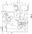
- Figs. 2 , 4 , 5 , 7 , and 8 schematically depict the non-condensable gas recovery system not according to the invention and configured for the enhanced recovery of a crude non-condensable gas stream, such as a crude neon containing vapor stream.
- an embodiment of the non-condensable gas recovery system 100 comprises a non-condensable stripping column (NSC) 210; a stripping column condenser 220, a cold compressor 230, and a neon upgrader 240.
- the non-condensable stripping column 210 is configured to receive a portion of nitrogen shelf vapor 215 from the higher pressure column 72 and a recycled portion of the boil-off nitrogen vapor 225 from the stripping column condenser 220. These two streams 215, 225 are combined and then further compressed in the nitrogen cold compressor 230.
- the further compressed nitrogen stream 235 is introduced proximate the bottom of the non-condensable stripping column 210 as an ascending vapor stream while the descending liquid reflux for the non-condensable stripping column 210 includes: (i) a stream of liquid nitrogen exiting the main condenser-reboiler 75; (ii) a stream of liquid nitrogen condensate exiting the stripping column condenser 227; and (iii) a stream of liquid nitrogen condensate 245 exiting the neon upgrader 240 (i.e. reflux condenser 242 ).
- the non-condensable stripping column 210 produces liquid nitrogen bottoms 212 and an overhead gas 214 containing higher concentrations of neon that is fed into stripping column condenser 220.
- the non-condensable stripping column 210 operates at a higher pressure than that of the higher pressure column 72 of the air separation unit 10 in order to provide the heat transfer temperature difference for the stripping column condenser 220. Because the non-condensable stripping column 210 is operated at a higher pressure than the high pressure column 72, the non-condensable stripping column 210 is preferably positioned at lower elevation than the stream of liquid nitrogen exiting the main condenser-reboiler 75 (i.e. shelf liquid take-off from high pressure column) such that descending liquid reflux would be fed to the non-condensable stripping column 210 by gaining gravity head. As the ascending vapor (i.e.
- stripping vapor rises along the non-condensable stripping column 210, the mass transfer occurring in the non-condensable stripping column 210 will concentrate the heavier components like oxygen, argon, nitrogen in the descending liquid phase, while the ascending vapor phase is enriched in light components like neon, hydrogen, and helium. As indicated above, the ascending vapor is introduced or fed to stripping column condenser 220.
- the stripping column condenser 220 is preferably a reflux type or non-reflux type brazed aluminum heat exchanger preferably integrated with the non-condensable stripping column 210.
- a small stream or portion of the nitrogen rich liquid column bottoms 212 from the non-condensable stripping column 210 provides the first condensing medium 216 for the stripping column condenser 220 while the remaining portion of the nitrogen rich liquid column bottoms 212 is the liquid nitrogen reflux stream 218 that is subcooled in a subcooler unit 99 against a stream of waste nitrogen 93 from the air separation unit 10.
- Portions of the subcooled liquid nitrogen reflux stream 218 may optionally be taken as liquid nitrogen product 217, diverted to the neon upgrader 240 or expanded in valve 219 and returned as a reflux stream 260 to the lower pressure column 74 of the air separation unit 10.
- the illustrated subcooler unit 99 may be an existing subcooler in the air separation unit 10 or may be a standalone subcooler unit that forms part of the non-condensable gas recovery system 100.
- the boil-off nitrogen vapor 225 from the stripping column condenser 220 is recycled back to the non-condensable stripping column 210 via the nitrogen cold compressor 230.
- non-condensables such as hydrogen, helium, neon are withdrawn from the non-condensable vent port as a non-condensable containing vent stream 229 which is directed or fed to the neon upgrader 240.
- the neon upgrader 240 preferably comprises a liquid nitrogen reflux condenser 242, a phase separator 244, and a nitrogen flow control valve 246.
- the liquid nitrogen reflux condenser 242 is preferably a reflux type brazed aluminum heat exchanger that condenses the non-condensable containing vent stream 229 against a second condensing medium 248, preferably a portion of the subcooled liquid nitrogen reflux stream.
- the boil-off stream 249 is removed from the neon recovery system 100 and fed into the waste stream 93.
- the residual vapor that does not condense within the liquid nitrogen reflux condenser 242 is withdrawn from the top of the liquid nitrogen reflux condenser 242 as a crude neon vapor stream 250 that contains greater than about 50% mole fraction of neon.
- the crude neon vapor stream preferably further contains greater than about 10% mole fraction of helium.
- the overall neon recovery for the illustrated non-condensable gas recovery system 100 is above 95%.
- An additional benefit of the depicted non-condensable gas recovery system 100 is that there is minimal liquid nitrogen consumption and since much of the liquid nitrogen is fed to the lower pressure column 74 of the air separation unit 10, there is minimal impact on the separation and recovery of other product slates for the air separation unit 10. This is because using an efficient cold compression system to recycle the boil-off nitrogen to the non-condensable stripping column and use of the nitrogen-rich column bottoms to provide refrigeration duty for the stripping column condenser 220.
- Fig. 4 and Fig. 5 are quite similar to that shown in Fig. 2 with corresponding elements and streams having corresponding reference numerals but numbered in the 300 series in Fig. 4 and in the 400 series in Fig. 5 .
- the primary differences between Fig. 2 and the embodiments of Figs. 4 and 5 being: the arrangement of the stripping column condenser 320, 420 and condensing mediums 322, 422; the elimination of nitrogen cold compressor 230; and the integration of the stripping column condenser 320, 420 with the distillation column system 70 of the air separation unit 10.
- the stripping column condenser 320 is a thermosyphon type condenser that may be a shell and tube condenser or a brazed aluminum heat exchanger that releases the non-condensable containing vent stream 329 into the reflux condenser 342 of the neon upgrader 340.
- the stripping column condenser 420 is a once-through boiling type condenser that may be a reflux type or non-reflux type condensing brazed aluminum heat exchanger that releases the non-condensable containing vent stream 429 into the reflux condenser 442 of the neon upgrader 440.
- the condensing medium for the stripping column condenser 320, 420 is a stream of liquid oxygen 322, 422 taken from the lower pressure column 72 of the air separation unit 10 and the boiled oxygen 324, 424 is returned to the lower pressure column 72 of the air separation unit 10. More specifically, liquid oxygen is preferably withdrawn from the sump of the lower pressure column 74 of the air separation unit 10 and fed by gravity to the boiling side of the stripper column condenser 320, 420. The liquid oxygen boils in the stripper column condenser 320, 420 to provide the refrigeration for vapor partial condensation.
- the stripper column condenser 320,420 operates at higher pressure than lower pressure column 74 of the air separation unit 10, the boil-off oxygen vapor 324, 424 is returned back to a location proximate the bottom of lower pressure column 74.
- the stripping column condenser 320, 420 is positioned below the lower pressure column sump to allow the oxygen flow to be driven by gravity in the embodiments shown in Fig. 4 and Fig. 5 .
- shelf vapor 315, 415 from the top of the high pressure column 72 is fed to the bottom of the non-condensable stripping column 320 as the ascending vapor while the descending liquid reflux for the non-condensable stripping column includes: (i) a stream of liquid nitrogen exiting the main condenser-reboiler 75; (ii) a stream of liquid nitrogen condensate exiting the stripping column condenser 327, 427; and (iii) a stream of liquid nitrogen condensate 345, 445 exiting the neon upgrader 340, 440 (i.e. reflux condenser 342, 442).
- the heavier components like oxygen, argon, nitrogen are concentrated in the descending liquid phase, while the ascending vapor phase is enriched in light components like neon, hydrogen, and helium.
- all of the liquid nitrogen bottoms 312, 412 from the non-condensable stripping column 310, 410 provide the liquid nitrogen reflux stream 318, 418 that is subcooled in a subcooler unit 99 against a stream of waste nitrogen 93 from the air separation unit 10.
- portions of the subcooled liquid nitrogen reflux stream may optionally be taken as liquid nitrogen product 317, 417, diverted as stream 348, 448 to the liquid nitrogen reflux condenser 342, 442 or expanded in valve 319, 419 and returned as a reflux stream 360, 460 to the lower pressure column 74 of air separation unit 10.
- the neon upgrader 340, 440 of Figs. 4 and 5 preferably comprises a liquid nitrogen reflux condenser 342, 442; a phase separator 344,444; and a nitrogen flow control valve 346, 446.
- the liquid nitrogen reflux condenser 342, 442 condenses the non-condensable containing vent stream 329, 429 against a second condensing medium 348, 448 preferably a portion of the subcooled liquid nitrogen reflux stream.
- the boil-off stream 349, 449 is removed from the neon recovery system 100 and fed into the waste stream 93.
- the residual vapor that does not condense within the liquid nitrogen reflux condenser 342, 442 is withdrawn from the top of the liquid nitrogen reflux condenser 342, 442 as a crude neon vapor stream 350, 450.
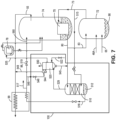
- non-condensable gas recovery system 100 comprises a non-condensable stripping column (NSC) 510, 610 and a condenser-reboiler 520, 620.
- the non-condensable stripping columns 510, 610 illustrated in Figs. 7 and 8 are configured to receive a portion of nitrogen shelf vapor 515, 615 from the higher pressure column 72 which is introduced proximate the bottom of the non-condensable stripping column 510, 610 as an ascending vapor stream.
- the descending liquid reflux for the non-condensable stripping column 510, 610 includes: (i) a stream of liquid nitrogen 80 exiting the main condenser-reboiler 75; and (ii) a stream of liquid nitrogen condensate 545, 645 exiting the condenser-reboiler 520, 620.
- the ascending vapor i.e. stripping vapor
- the mass transfer occurring in the non-condensable stripping column 510, 610 will concentrate the heavier components like oxygen, argon, and nitrogen in the descending liquid phase while the ascending vapor phase is enriched in lighter components like neon, hydrogen, and helium.
- the non-condensable stripping column 510, 610 produces liquid nitrogen bottoms 512, 612 and an overhead gas 529, 629 containing higher concentrations of non-condensables that is fed into the condenser-reboiler 520, 620.
- the liquid nitrogen bottoms 512, 612 from the non-condensable stripping column 510, 610 forms a liquid nitrogen reflux stream 518, 618 and is preferably subcooled in a subcooler unit 99 against a stream of waste nitrogen 93 from the air separation unit 10. Portions of the subcooled liquid nitrogen reflux stream may optionally be taken as liquid nitrogen product 517, 617; diverted to the condenser-reboiler 520, 620; or expanded in valve 519, 619 and returned as a reflux stream 560, 660 to the lower pressure column 74 of the air separation unit 10. Similar to the earlier described embodiments, the illustrated subcooler unit 99 may be an existing subcooler in the air separation unit 10 or may be a standalone unit that forms part of the non-condensable gas recovery system 100.
- the condenser-reboiler 520, 620 is preferably a two stage condenser-reboiler that provides two levels of refrigeration to partially condense most of the overhead vapor 529, 629 from the non-condensable stripping column 510, 610.
- the 7 is configured to receive the overhead gas 529 containing neon and other non-condensables from the non-condensable stripping column 510, a first condensing medium 522 that comprises a kettle boiling stream diverted from a nitrogen subcooler of the air separation unit 10, and a second condensing medium 548 that comprises a throttled portion via valve 546 of the subcooled liquid nitrogen reflux stream.
- the two-stage reflux condenser-reboiler 520 is configured to produce a stream of liquid nitrogen condensate 545 that is returned as reflux to the non-condensable stripping column 510, a two phase boil-off stream 525 that is directed to the argon condenser 78 of the air separation unit 10, and a crude neon vapor stream 550 that is withdrawn from the top of the condenser-reboiler 520 and that contains greater than about 50% mole fraction of neon.
- the crude neon vapor stream may further contain greater than about 10% mole fraction of helium.
- Boil-off stream 549 is removed from phase separator 544 and fed into the waste stream 93.
- the overall neon recovery for the illustrated non-condensable gas recovery system is above 95%.
- An additional benefit of the depicted non-condensable gas recovery system is that there is minimal liquid nitrogen consumption and since much of the liquid nitrogen is recycled back to the lower pressure column, there is minimal impact on the separation and recovery of other product slates in the air separation unit 10.
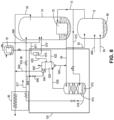
- the embodiment of Fig. 8 is quite similar to that shown in Fig. 7 with corresponding elements and streams having corresponding reference numerals but numbered in the 600 series in Fig. 8 and in the 500 series in Fig. 7 .
- the items designated by reference numerals 522, 525, 544, 545, 546, 548, 549, and 550 in Fig. 7 are the same or similar to the , the items designated by reference numerals 622, 625, 644, 645, 646, 648, 649, and 650 in Fig. 8 , respectively.
- the boiling stream 625 produced by the two stage reflux condenser-reboiler 620 is directed to a phase separator 670 with the resulting vapor stream 671 and liquid stream 672 being returned to intermediate locations of the lower pressure column 74 of the air separation unit 10.
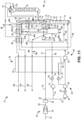
- Figs. 10 and 12 refer to embodiments of the invention and schematically depict the non-condensable gas recovery system configured for the enhanced recovery of a crude neon vapor stream and a crude xenon and krypton liquid stream.
- an embodiment of the non-condensable gas recovery system 100 comprises a non-condensable stripping column 710; a xenon-krypton column 770; a condenser-reboiler 720 disposed in the xenon-krypton column 770, and a neon upgrader 740.
- the non-condensable stripping column 710 is configured to receive a portion of nitrogen shelf vapor 715 from the higher pressure column 72 and introduced proximate the bottom of the non-condensable stripping column 710 as an ascending vapor stream while the descending liquid reflux for the non-condensable stripping column 710 includes: (i) a stream of liquid nitrogen exiting the main condenser-reboiler 75; (ii) a stream of liquid nitrogen condensate 727 exiting the condenser-reboiler 720; and (iii) a stream of liquid nitrogen condensate 745 exiting the neon upgrader 740 (i.e. reflux condenser 742 ).
- the mass transfer occurring in the non-condensable stripping column 710 will concentrate the heavier components like nitrogen in the descending liquid phase, while the ascending vapor phase is enriched in light components like neon, hydrogen, and helium.
- the ascending vapor is introduced or fed to condenser-reboiler 720.
- the non-condensable stripping column 710 produces liquid nitrogen bottoms 712 and an overhead gas 714 containing higher concentrations of rare gases that is fed into the condenser-reboiler 720 in the xenon-krypton column 770.
- the nitrogen rich liquid column bottoms 712 is extracted from the non-condensable stripping column 710 as liquid nitrogen reflux stream 718.
- the liquid nitrogen reflux stream 718 is subcooled in a subcooler unit 99 against a stream of waste nitrogen 93 from the air separation unit 10. Portions of the subcooled liquid nitrogen reflux stream 218 may optionally be taken as liquid nitrogen product 717, diverted to the neon upgrader 740 or expanded in valve 719 and returned as a reflux stream 760 to the lower pressure column 74 of the air separation unit 10.
- the subcooler unit 99 may be an existing subcooler in the air separation unit 10 or may be a standalone subcooler unit that forms part of the non-condensable gas recovery system 100.
- the xenon-krypton column 770 receives streams of liquid oxygen from the lower pressure column 74 of the air separation unit. Specifically, a stream of liquid oxygen 90 is withdrawn from the sump of the lower pressure column 74, pumped via pump 180 with the resulting pumped liquid oxygen stream 775 being fed to two locations on the xenon-krypton column 770.
- the primary liquid oxygen feed is proximate the top of the xenon-krypton column 770 serving as reflux for the xenon-krypton column 770.
- the secondary liquid oxygen feed is released in the xenon-krypton column 770 at an intermediate or lower section proximate the column sump for contaminant control purposes while maintaining xenon and krypton recovery.
- the liquid in the sump of the xenon-krypton column 770 is reboiled by the condenser-reboiler 720 against the condensing overhead vapor from the non-condensable stripping column 710.
- the boil-off oxygen vapor rises through the xenon-krypton column 770, enriching in oxygen and argon while the liquid concentrates in heavier components such as krypton and xenon.
- the krypton/xenon enriched oxygen liquid is withdrawn from xenon-krypton column 770 sump as a crude xenon and krypton liquid product 780
- the condenser-reboiler 720 is a once-through boiling type condenser that may be a reflux type or non-reflux type condensing brazed aluminum heat exchanger or thermosyphon type condenser that may be shell and tube condenser or brazed aluminum heat exchanger.
- non-condensables such as hydrogen, helium, neon are withdrawn from the non-condensable vent port as a non-condensable containing vent stream 729 which is directed or fed to the neon upgrader 740.
- the neon upgrader 740 preferably comprises a liquid nitrogen reflux condenser 742, a phase separator 744, and a nitrogen flow control valve 746.
- the liquid nitrogen reflux condenser 742 preferably condenses the non-condensable containing vent stream 729 against a second condensing medium 748, preferably a portion of the subcooled liquid nitrogen reflux stream.
- the boil-off stream 749 from the liquid nitrogen reflux condenser 742 is phase separated with the vapor being removed from the rare gas recovery system 100 and fed into the waste stream 93.
- the residual vapor that does not condense within the liquid nitrogen reflux condenser 742 is withdrawn from the top of the liquid nitrogen reflux condenser 742 as a crude neon vapor stream 750 that contains greater than about 50% mole fraction of neon.
- the crude neon vapor stream preferably further contains greater than about 10% mole fraction of helium.
- Fig. 12 is quite similar to that shown in Fig. 10 with corresponding elements and streams having corresponding reference numerals but numbered in the 700 series in Fig. 10 and in the 800 series in Fig. 12 .
- the primary difference between the embodiment of Fig. 10 and the embodiment of Figs. 12 is the production of oxygen products from the air separation unit 10.
- liquid oxygen stream 90 is withdrawn from the lower pressure column 74 and pressurized in LOX pump 180.
- the pumped liquid oxygen is split into two or more streams including: a liquid oxygen stream 775 to be introduced into the xenon-krypton column 770; a liquid oxygen product stream 185; and/or an oxygen product stream 186 that is vaporized in the main or primary heat exchanger 52 to produce pressurized gaseous oxygen product.
- the oxygen-rich overhead 785 from the xenon-krypton column 770 is returned to the lower pressure column 74.
- the liquid oxygen stream 90 is withdrawn from the lower pressure column 74 and pressurized in LOX pump 180.
- the pumped liquid oxygen 875 is directed to the non-condensable gas recovery system 100 with the oxygen-rich overhead 885 from the xenon-krypton column 870 is directed as stream 890 to the main or primary heat exchanger 52 where it can be vaporized to produce gaseous oxygen product.
- the neon upgrader 840 of Fig. 12 comprises a liquid nitrogen reflux condenser 842; a phase separator 844; and a nitrogen flow control valve 846.
- the liquid nitrogen reflux condenser 842 condenses the non-condensable containing vent stream 829 against a second condensing medium 848 which is a portion of the subcooled liquid nitrogen reflux stream.
- the boil-off stream 849 is removed from the rare gas recovery system 100 and fed into the waste stream 93.
- the residual vapor that does not condense within the liquid nitrogen reflux condenser 842 is withdrawn from the top of the liquid nitrogen reflux condenser 842 as a crude neon vapor stream 850.
- the overall neon recovery for the illustrated non-condensable gas recovery system 100 is above 95%.
- An additional benefit of the depicted non-condensable gas recovery system 100 is that because the condenser-reboiler 720, 820 thermally links both the non-condensable stripping column 710,810 and the xenon-krypton column 770, 870 (i.e. neon enriched non-condensable gas on the condensing side and krypton/xenon enriched liquid from the boiling side of the condenser-reboiler 720, 820, the arrangement has the ability to co-produce rare gases. And since most of the nitrogen used in the rare-gas recovery system is returned to the distillation column system of the air separation unit 10, there is minimal impact on the separation and recovery of other product slates by the air separation unit 10.
- Table 1 shows the results of the computer based process simulation for the recovery system and associated methods described with reference to Fig. 2 .
- the air separation unit is operated with incoming feed air stream of 134719 m 3 /h (4757.56 kcfh) and 1072 m 3 /h (37.86 kcfh) of liquid air stream to the higher pressure column at roughly 668.8 kPa (97 psia).
- Neon recovery is calculated by taking the flow rate of the crude neon stream (4.5 m 3 /h (0.16 kcfh)) times the neon content in the crude neon stream (51.89%) and dividing that number (2.35 m 3 /h (0.083024 kcfh)) by the contained neon in both main air stream (134720 m 3 /h (4757.56 kcfh) * 0.00182%) and liquid air stream (1072 m 3 /h (37.86 kcfh) * 0.00182%) into the distillation column system.
- the make-up of the crude neon vapor stream includes 51.89% neon and 15.25% helium.
- Table 2 shows the results of the computer based process simulation for the neon recovery system and associated methods described with reference to Fig. 4 .
- the air separation unit is operated with incoming feed air stream of 134720 m 3 /h (4757.56 kcfh) and 1072 m 3 /h (37.86 kcfh) of liquid air stream to the higher pressure column at roughly 668.8 kPa (97 psia).
- Table 3 shows the results of the computer based process simulation for the neon recovery system and associated methods described with reference to Fig. 7 .
- the air separation unit is operated with incoming feed air stream of 134720 m 3 /h (4757.56 kcfh) and 1072 m 3 /h (37.86 kcfh) of liquid air stream to the higher pressure column at roughly 668.8 kPa (97 psia).
- Table 4 shows the results of the computer based process simulation for the rare gas recovery system and associated methods described with reference to Fig. 10 .
- the air separation unit is operated with incoming feed air stream of 134720 m 3 /h (4757.56 kcfh) and 1072 m 3 /h (37.86 kcfh) of liquid air stream to the higher pressure column at roughly 668.8 kPa (97 psia).
- Table 5 shows the results of the computer based process simulation for the rare gas recovery system and associated methods described with reference to Fig. 12 .
- the air separation unit is operated with incoming feed air stream of 134719 m 3 /h (4757.56 kcfh) and 1072 m 3 /h (37.86 kcfh) of liquid air stream to the higher pressure column at roughly 668.8 kPa (97 psia).
Landscapes
- Engineering & Computer Science (AREA)
- Physics & Mathematics (AREA)
- Mechanical Engineering (AREA)
- Thermal Sciences (AREA)
- General Engineering & Computer Science (AREA)
- Health & Medical Sciences (AREA)
- Emergency Medicine (AREA)
- Separation By Low-Temperature Treatments (AREA)
Claims (14)
- Lufttrenneinheit (10), die ein Edelgaswiederherstellungssystem (100) aufweist, die Lufttrenneinheit umfassend ein Hauptluftkompressionssystem (20), ein Vorreinigungssystem (28), ein Wärmetauschersystem (52) und ein Rektifikationskolonnensystem, das eine Hochdruckkolonne (72) und eine Niederdruckkolonne (74) aufweist, die in einer Wärmeübertragungsbeziehung über einen Hauptkondensatorverdampfer (75) verbunden ist, wobei das Edelgaswiederherstellungssystem (100) umfasst:eine nicht kondensierbare Abtriebkolonne (710), die konfiguriert ist, um einen Strom von stickstoffreichem Shelf-Dampf (715) von der Hochdruckkolonne (72) aufzunehmen, wobei die nicht kondensierbare Abtriebkolonne konfiguriert ist, um Flüssigstickstoffkolonnenböden (712) und ein Edelgas herzustellen, das Kopfdestillat (714) enthält;eine Xenon-Krypton-Kolonne (770), die in einer Wärmeübertragungsbeziehung mit der nicht kondensierbaren Abtriebkolonne (710) über einen Hilfskondensatorverdampfer (720) verbunden ist, wobei die Xenon-Krypton-Kolonne konfiguriert ist, um einen ersten Strom von flüssigem Sauerstoff (775), der aus der Niederdruckkolonne (74) (10) gepumpt wird, und einen ersten Boil-Off-Strom von sauerstoffreichem Dampf aus dem Hilfskondensatorverdampfer aufzunehmen, wobei die Xenon-Krypton-Kolonne konfiguriert ist, um ein Xenon und Krypton herzustellen, das Kolonnenböden und ein sauerstoffreiches Kopfdestillat (785) enthält, wobei ein Abschnitt des Xenon und Krypton, der Kolonnenböden enthält, als ein roher flüssiger Xenon- und Kryptonstrom (780) entnommen wird;wobei der Hilfskondensatorverdampfer (720) konfiguriert ist, um das Edelgas, das das Kopfdestillat (714) enthält, von der nicht kondensierbaren Abtriebkolonne (710) und einem zweiten flüssigen Sauerstoffstrom als die Kühlquelle aufzunehmen, wobei der Hilfskondensatorverdampfer ferner konfiguriert ist, um einen Kondensatrückflussstrom (727), der in die nicht kondensierbare Abtriebkolonne freigesetzt wird oder auf diese gerichtet ist, den ersten Boil-Off-Strom von sauerstoffreichem Dampf, der in die Xenon-Krypton-Kolonne freigesetzt wird, und einen nicht kondensierbaren, enthaltenden Entlüftungsstrom (729) herzustellen;dadurch gekennzeichnet, dass das Edelgaswiederherstellungssystem (100) ferner einen Rückflusskondendator (742) umfasst, der konfiguriert ist, um den nicht kondensierbaren, enthaltenden Entlüftungsstrom (729) von dem Hilfskondensatorverdampfer (720) und einem Kondensationsmedium (748) aufzunehmen, wobei der Rückflusskondensator ferner konfiguriert ist, um ein Kondensat (745), das auf die nicht kondensierbare Abtriebkolonne gerichtet ist, und einen rohen Neondampfstrom (750) herzustellen, der mehr als etwa 50 % Molenbruch von Neon enthält; undeinen Unterkühler (99), der konfiguriert ist, um den gesamten oder einen Abschnitt der Flüssigstickstoffkolonnenböden (712) zu unterkühlen, um einen unterkühlten Flüssigstickstoffstrom herzustellen;wobei das Kondensationsmedium für den Rückflusskondensator (742) ein Abschnitt (748) des unterkühlten Flüssigstickstoffstroms ist; wobeidie nicht kondensierbare Abtriebkolonne konfiguriert ist, um einen Abschnitt eines Flüssigstickstoffkondensatstroms (80) von dem Hauptkondensatorverdampfer (75) aufzunehmen; und wobei der zweite flüssige Sauerstoffstrom von der Niederdruckkolonne (74) stammt.
- Lufttrenneinheit (10), die ein Edelgaswiederherstellungssystem (100) nach Anspruch 1 aufweist, wobei der Rückflusskondensator (742) ferner konfiguriert ist, um den rohen Neondampfstrom (750), der mehr als etwa 10 % Molenbruch von Helium aufweist, herzustellen.
- Lufttrenneinheit (10), die ein Edelgaswiederherstellungssystem (100) nach Anspruch 1 aufweist, wobei die Xenon-Krypton-Kolonne (770) ferner konfiguriert ist, um das gesamte oder einen Abschnitt des sauerstoffreichen Kopfdestillats zurück in die Niederdruckkolonne (74) zu leiten.
- Lufttrenneinheit (10), die ein Edelgaswiederherstellungssystem (100) nach Anspruch 1 aufweist, wobei die Xenon-Krypton-Kolonne (770) ferner konfiguriert ist, um das gesamte oder einen Abschnitt des sauerstoffreichen Kopfdestillats als ein gasförmiges Sauerstoffprodukt zu entnehmen.
- Lufttrenneinheit (10), die ein Edelgaswiederherstellungssystem (100) nach Anspruch 1 aufweist, wobei der Unterkühler (99) ferner konfiguriert ist, um den Flüssigstickstoffkolonnenboden (712) über indirekten Wärmeaustausch mit einem Stickstoffkolonnenkopfdestillat der Niederdruckkolonne (74) zu unterkühlen.
- Lufttrenneinheit (10), die ein Edelgaswiederherstellungssystem (100) nach Anspruch 1 aufweist, wobei der Unterkühler ferner konfiguriert ist, um einen ersten Abschnitt (748) des unterkühlten Flüssigstickstoffstroms zu dem Rückflusskondensator (742) als das Kondensationsmedium und einen zweiten Abschnitt des unterkühlten Flüssigstickstoffstroms zu der Niederdruckkolonne (74) als einen Rückflussstrom (760) zu leiten.
- Lufttrenneinheit (10), die ein Edelgaswiederherstellungssystem (100) nach Anspruch 1 aufweist, wobei der Unterkühler (99) ferner konfiguriert ist, um einen ersten Abschnitt des unterkühlten Flüssigstickstoffstroms in den Rückflusskondensator (742) als das Kondensationsmedium; einen zweiten Abschnitt des unterkühlten Flüssigstickstoffstroms in die Niederdruckkolonne (74) als einen Rückflussstrom zu leiten; und um einen dritten Abschnitt als einen Flüssigstickstoffproduktstrom zu entnehmen.
- Verfahren für eine Edelgaswiederherstellung in einer Lufttrenneinheit (10), die Lufttrenneinheit umfassend ein Hauptluftkompressionssystem (20), ein Vorreinigungssystem (28), ein Wärmetauschersystem (52) und ein Rektifikationskolonnensystem, das eine Hochdruckkolonne (72) und eine Niederdruckkolonne (74) aufweist, die in einer Wärmeübertragungsbeziehung über einen Hauptkondensatorreaktor (75) verbunden ist, das Verfahren umfassend die Schritte:Leiten eines Stroms von stickstoffreichem Shelf-Dampf von der Hochdruckkolonne (72) zu einer nicht kondensierbaren Abtriebkolonne (710), die konfiguriert ist, um einen Flüssigstickstoffkolonnenboden und ein Edelgas zu erzeugen, das Kopfdestillat enthält;Kondensieren von Stickstoff aus dem Edelgas, das Kopfdestillat enthält, in einem Hilfskondensatorverdampfer (720) gegen einen ersten Strom von flüssigem Sauerstoff, um ein Kondensat und einen nicht kondensierbaren, enthaltenden Entlüftungsstrom zu erzeugen, während der flüssige Sauerstoff verdampft oder teilweise verdampft wird, um einen ersten Boil-Off-Strom herzustellen, der aus der Verdampfung oder teilweisen Verdampfung des flüssigen Sauerstoffs ausgebildet wird;Pumpen eines zweiten Stroms von flüssigem Sauerstoff (775) von der Niederdruckkolonne (74) der Lufttrenneinheit (10) zu einer Xenon-Krypton-Kolonne (770), die in einer Wärmeübertragungsbeziehung mit der nicht kondensierbaren Abtriebkolonne (710) über den Hilfskondensatorverdampfer (720) verbunden ist;Lösen des ersten Boil-Off-Stroms von dem Hilfskondensatorverdampfer (720) in die Xenon-Krypton-Kolonne (710);und Entnehmen eines Abschnitts des Xenon und Krypton, der Kolonnenböden enthält, als einen rohen flüssigen Xenon-und Kryptonstrom (780);gekennzeichnet durch die Schritte:Leiten eines Stroms von Flüssigstickstoff (80) von dem Hauptkondensatorverdampfer (75) zu der nicht kondensierbaren Abtriebkolonne (710);Unterkühlen des gesamten oder eines Abschnitts des Flüssigstickstoffkolonnenbodens (718), um einen unterkühlten Flüssigstickstoffstrom (748) herzustellen; undLeiten des nicht kondensierbaren, enthaltenden Entlüftungsstroms (729) und eines ersten Abschnitts des unterkühlten Flüssigstickstoffstroms (748) zu einem Rückflusskondensator (742), wobei der Rückflusskondensator konfiguriert ist, um einen Kondensatstrom, der auf die nicht kondensierbare Abtriebkolonne (710) gerichtet ist, einen zweiten Boil-Off-Strom, der aus der Verdampfung oder teilweisen Verdampfung des Abschnitts des unterkühlten Flüssigstickstoffstroms ausgebildet wird, und einen rohen Neondampfstrom (750) herzustellen, der mehr als etwa 50 % Molenbruch von Neon enthält;wobei der erste Strom von flüssigem Sauerstoff von der Niederdruckkolonne (74) der Lufttrenneinheit stammt.
- Verfahren für eine Edelgaswiederherstellung nach Anspruch 8, wobei der rohe Neondampfstrom (750) ferner mehr als etwa 10 % Molenbruch von Helium enthält.
- Verfahren für eine Edelgaswiederherstellung nach Anspruch 8, ferner umfassend den Schritt des Leitens des gesamten oder eines Abschnitts des sauerstoffreichen Kopfdestillats zurück zu der Niederdruckkolonne (74) der Lufttrenneinheit (10).
- Verfahren für eine Edelgaswiederherstellung nach Anspruch 8, ferner umfassend den Schritt des Entnehmens des gesamten oder eines Abschnitts des sauerstoffreichen Kopfdestillats als ein gasförmiges Sauerstoffprodukt.
- Verfahren für eine Edelgaswiederherstellung nach Anspruch 8, wobei der Schritt des Unterkühlens des gesamten oder eines Abschnitts des Flüssigstickstoffkolonnenbodens (712), um einen unterkühlten Flüssigstickstoffstrom herzustellen, ferner das Unterkühlen des gesamten oder eines Abschnitts des Flüssigstickstoffkolonnenbodens über indirekten Wärmeaustausch mit einem Stickstoffkolonnenkopfdestillat der Niederdruckkolonne (74) der Lufttrenneinheit (10) umfasst, um den unterkühlten Flüssigstickstoffstrom herzustellen;
- Verfahren für eine Edelgaswiederherstellung nach Anspruch 8, ferner umfassend den Schritt des Leitens eines zweiten Abschnitts des unterkühlten Flüssigstickstoffstroms in die Niederdruckkolonne (74) der Lufttrenneinheit (10) als einen Rückflussstrom.
- Verfahren für eine Edelgaswiederherstellung nach Anspruch 13, ferner umfassend den Schritt des Entnehmens eines dritten Abschnitts des unterkühlten Flüssigstickstoffstroms als einen Flüssigstickstoffproduktstrom (717).
Applications Claiming Priority (2)
| Application Number | Priority Date | Filing Date | Title |
|---|---|---|---|
| US15/695,381 US10295254B2 (en) | 2017-09-05 | 2017-09-05 | System and method for recovery of non-condensable gases such as neon, helium, xenon, and krypton from an air separation unit |
| PCT/US2018/039757 WO2019050611A1 (en) | 2017-09-05 | 2018-06-27 | SYSTEM AND METHOD FOR RECOVERING NON-CONDENSABLE GASES SUCH AS NEON, HELIUM, XENON AND KRYPTON FROM AN AIR SEPARATION UNIT |
Publications (3)
| Publication Number | Publication Date |
|---|---|
| EP3679310A1 EP3679310A1 (de) | 2020-07-15 |
| EP3679310C0 EP3679310C0 (de) | 2023-08-23 |
| EP3679310B1 true EP3679310B1 (de) | 2023-08-23 |
Family
ID=62976234
Family Applications (1)
| Application Number | Title | Priority Date | Filing Date |
|---|---|---|---|
| EP18743231.5A Active EP3679310B1 (de) | 2017-09-05 | 2018-06-27 | System und verfahren zur gewinnung von neon und anderen nichtkondensierbaren gasen, sowie von xenon und krypton aus einer luftzerlegungsanlage |
Country Status (7)
| Country | Link |
|---|---|
| US (1) | US10295254B2 (de) |
| EP (1) | EP3679310B1 (de) |
| KR (1) | KR102339234B1 (de) |
| CN (1) | CN111065872B (de) |
| BR (1) | BR112020004022B1 (de) |
| CA (1) | CA3073932C (de) |
| WO (1) | WO2019050611A1 (de) |
Families Citing this family (15)
| Publication number | Priority date | Publication date | Assignee | Title |
|---|---|---|---|---|
| WO2018042336A2 (en) * | 2016-08-30 | 2018-03-08 | 8 Rivers Capital, Llc | Cryogenic air separation method for producing oxygen at high pressures |
| GB2571569A (en) * | 2018-03-02 | 2019-09-04 | Linde Ag | Cooling system |
| WO2021230913A1 (en) * | 2020-05-15 | 2021-11-18 | Praxair Technology, Inc. | Enhancements to a moderate pressure nitrogen and argon producing cryogenic air separation unit |
| CN112129040B (zh) * | 2020-09-27 | 2024-02-20 | 杭氧集团股份有限公司 | 一种液氙冷却、氙气再液化撬装装置及其方法 |
| US11512897B2 (en) * | 2021-01-14 | 2022-11-29 | Air Products And Chemicals, Inc. | Fluid recovery process and apparatus |
| CN112557157B (zh) * | 2021-02-28 | 2021-05-04 | 中国工程物理研究院核物理与化学研究所 | 一种基于特定装置的空气样品中氙的分离纯化收集方法 |
| TWI808870B (zh) * | 2022-08-11 | 2023-07-11 | 印能科技股份有限公司 | 氣體回收設備 |
| KR102909174B1 (ko) * | 2022-10-12 | 2026-01-08 | 한국가스공사 | 희귀가스 생산 시스템 및 이를 포함하는 액화수소 인수기지 |
| EP4417916A1 (de) * | 2023-02-17 | 2024-08-21 | Linde GmbH | Verfahren und vorrichtung zur kryogenen luftzerlegung mit einer geteilten hochdruckkolonne |
| CN115839601B (zh) * | 2023-02-27 | 2023-05-12 | 中科富海(杭州)气体工程科技有限公司 | 液体空分及氪氙预浓缩一体化设备 |
| US20240375958A1 (en) | 2023-05-12 | 2024-11-14 | Air Products And Chemicals, Inc. | Process and Apparatus for Xenon and or Krypton Recovery |
| CN117053502A (zh) * | 2023-09-06 | 2023-11-14 | 上海启元气体发展有限公司 | 一种制取粗氖氦的装置及制取方法 |
| JP2025092098A (ja) * | 2023-12-08 | 2025-06-19 | エア・ウォーター株式会社 | ネオンの製造方法およびネオンの製造装置 |
| CN117516067A (zh) * | 2023-12-15 | 2024-02-06 | 河南大学 | 一种提取氦氖氪氙的高效节能耦合精馏混合塔装置和方法 |
| US20250290692A1 (en) * | 2024-03-18 | 2025-09-18 | Air Products And Chemicals, Inc. | Apparatus and process for providing nitrogen and oxygen |
Family Cites Families (13)
| Publication number | Priority date | Publication date | Assignee | Title |
|---|---|---|---|---|
| US2497589A (en) | 1947-04-18 | 1950-02-14 | Air Reduction | Separation and recovery of the constituents of air |
| SU585728A1 (ru) | 1975-07-21 | 1981-03-23 | Одесский Технологический Институтхолодильной Промышленности | Способ обогащени неоно-гелиевой смеси |
| JPS6241572A (ja) | 1985-08-17 | 1987-02-23 | 日本酸素株式会社 | 空気分離装置におけるネオン及びヘリウムの濃縮方法 |
| JPH0746024B2 (ja) | 1986-02-20 | 1995-05-17 | 日本酸素株式会社 | 空気分離装置におけるクリプトン,キセノンの濃縮方法及び装置 |
| DE3722746A1 (de) | 1987-07-09 | 1989-01-19 | Linde Ag | Verfahren und vorrichtung zur luftzerlegung durch rektifikation |
| US5100446A (en) | 1991-01-07 | 1992-03-31 | Union Carbide Industrial Gases Technology Corporation | Crude neon production system |
| US5167125A (en) | 1991-04-08 | 1992-12-01 | Air Products And Chemicals, Inc. | Recovery of dissolved light gases from a liquid stream |
| JP3299069B2 (ja) | 1995-03-24 | 2002-07-08 | 日本エア・リキード株式会社 | 空気低温分離装置及びその分離方法 |
| US7299656B2 (en) | 2005-02-18 | 2007-11-27 | Praxair Technology, Inc. | Cryogenic rectification system for neon production |
| US20100221168A1 (en) | 2009-03-02 | 2010-09-02 | Joseph Theodore Bernstein | Cryogenic system for neon production |
| EP2322888B1 (de) | 2009-11-13 | 2019-01-02 | Linde Aktiengesellschaft | Verfahren und Vorrichtung zur Gewinnung eines Helium-Neon-Konzentrats aus Luft |
| CN104990366B (zh) | 2015-06-16 | 2017-11-14 | 浙江新锐空分设备有限公司 | 一种从空分装置液氮中提取粗氖氦产品的方法 |
| US10995982B2 (en) * | 2016-01-11 | 2021-05-04 | Praxair Technology, Inc. | System and method for rare gas recovery |
-
2017
- 2017-09-05 US US15/695,381 patent/US10295254B2/en active Active
-
2018
- 2018-06-27 CA CA3073932A patent/CA3073932C/en active Active
- 2018-06-27 EP EP18743231.5A patent/EP3679310B1/de active Active
- 2018-06-27 KR KR1020207008157A patent/KR102339234B1/ko active Active
- 2018-06-27 CN CN201880055204.1A patent/CN111065872B/zh active Active
- 2018-06-27 BR BR112020004022-3A patent/BR112020004022B1/pt active IP Right Grant
- 2018-06-27 WO PCT/US2018/039757 patent/WO2019050611A1/en not_active Ceased
Also Published As
| Publication number | Publication date |
|---|---|
| KR102339234B1 (ko) | 2021-12-14 |
| BR112020004022B1 (pt) | 2024-01-30 |
| CN111065872A (zh) | 2020-04-24 |
| CN111065872B (zh) | 2022-01-11 |
| EP3679310C0 (de) | 2023-08-23 |
| EP3679310A1 (de) | 2020-07-15 |
| BR112020004022A2 (pt) | 2020-09-08 |
| US10295254B2 (en) | 2019-05-21 |
| CA3073932C (en) | 2022-05-24 |
| US20190072326A1 (en) | 2019-03-07 |
| WO2019050611A1 (en) | 2019-03-14 |
| CA3073932A1 (en) | 2019-03-14 |
| KR20200040297A (ko) | 2020-04-17 |
Similar Documents
| Publication | Publication Date | Title |
|---|---|---|
| CA3073932C (en) | System and method for recovery of non-condensable gases such as neon, helium, xenon, and krypton from an air separation unit | |
| US10408536B2 (en) | System and method for recovery of neon and helium from an air separation unit | |
| US20080223077A1 (en) | Air separation method | |
| US9222726B2 (en) | Air separation method and apparatus with improved argon recovery | |
| US20220146195A1 (en) | Method for flexible recovery of argon from a cryogenic air separation unit | |
| US20230221069A1 (en) | Integrated nitrogen liquefier for a nitrogen and argon producing cryogenic air separation unit | |
| US11933539B2 (en) | Cryogenic air separation unit with argon condenser vapor recycle | |
| US20130019634A1 (en) | Air separation method and apparatus | |
| US11933538B2 (en) | System and method for recovery of nitrogen, argon, and oxygen in moderate pressure cryogenic air separation unit | |
| US20210356205A1 (en) | Enhancements to a moderate pressure nitrogen and argon producing cryogenic air separation unit | |
| BR112020003998B1 (pt) | Sistema e método de recuperação de neônio | |
| JPH08210771A (ja) | 空気を分離して窒素生成物を得る方法および装置 |
Legal Events
| Date | Code | Title | Description |
|---|---|---|---|
| STAA | Information on the status of an ep patent application or granted ep patent |
Free format text: STATUS: UNKNOWN |
|
| STAA | Information on the status of an ep patent application or granted ep patent |
Free format text: STATUS: THE INTERNATIONAL PUBLICATION HAS BEEN MADE |
|
| PUAI | Public reference made under article 153(3) epc to a published international application that has entered the european phase |
Free format text: ORIGINAL CODE: 0009012 |
|
| STAA | Information on the status of an ep patent application or granted ep patent |
Free format text: STATUS: REQUEST FOR EXAMINATION WAS MADE |
|
| 17P | Request for examination filed |
Effective date: 20200401 |
|
| AK | Designated contracting states |
Kind code of ref document: A1 Designated state(s): AL AT BE BG CH CY CZ DE DK EE ES FI FR GB GR HR HU IE IS IT LI LT LU LV MC MK MT NL NO PL PT RO RS SE SI SK SM TR |
|
| AX | Request for extension of the european patent |
Extension state: BA ME |
|
| RIN1 | Information on inventor provided before grant (corrected) |
Inventor name: TUO, HANFEI Inventor name: SHELAT, MAULIK, R. Inventor name: DEGENSTEIN, NICK, J. Inventor name: DRAY, JAMES, R. Inventor name: CHAKRAVARTHY, VIJAYARAGHAVAN, S. |
|
| DAV | Request for validation of the european patent (deleted) | ||
| DAX | Request for extension of the european patent (deleted) | ||
| GRAP | Despatch of communication of intention to grant a patent |
Free format text: ORIGINAL CODE: EPIDOSNIGR1 |
|
| STAA | Information on the status of an ep patent application or granted ep patent |
Free format text: STATUS: GRANT OF PATENT IS INTENDED |
|
| INTG | Intention to grant announced |
Effective date: 20230612 |
|
| GRAS | Grant fee paid |
Free format text: ORIGINAL CODE: EPIDOSNIGR3 |
|
| GRAA | (expected) grant |
Free format text: ORIGINAL CODE: 0009210 |
|
| STAA | Information on the status of an ep patent application or granted ep patent |
Free format text: STATUS: THE PATENT HAS BEEN GRANTED |
|
| AK | Designated contracting states |
Kind code of ref document: B1 Designated state(s): AL AT BE BG CH CY CZ DE DK EE ES FI FR GB GR HR HU IE IS IT LI LT LU LV MC MK MT NL NO PL PT RO RS SE SI SK SM TR |
|
| REG | Reference to a national code |
Ref country code: GB Ref legal event code: FG4D |
|
| REG | Reference to a national code |
Ref country code: CH Ref legal event code: EP |
|
| REG | Reference to a national code |
Ref country code: IE Ref legal event code: FG4D |
|
| REG | Reference to a national code |
Ref country code: DE Ref legal event code: R096 Ref document number: 602018055941 Country of ref document: DE |
|
| U01 | Request for unitary effect filed |
Effective date: 20230921 |
|
| U07 | Unitary effect registered |
Designated state(s): AT BE BG DE DK EE FI FR IT LT LU LV MT NL PT SE SI Effective date: 20231004 |
|
| PG25 | Lapsed in a contracting state [announced via postgrant information from national office to epo] |
Ref country code: GR Free format text: LAPSE BECAUSE OF FAILURE TO SUBMIT A TRANSLATION OF THE DESCRIPTION OR TO PAY THE FEE WITHIN THE PRESCRIBED TIME-LIMIT Effective date: 20231124 |
|
| PG25 | Lapsed in a contracting state [announced via postgrant information from national office to epo] |
Ref country code: IS Free format text: LAPSE BECAUSE OF FAILURE TO SUBMIT A TRANSLATION OF THE DESCRIPTION OR TO PAY THE FEE WITHIN THE PRESCRIBED TIME-LIMIT Effective date: 20231223 |
|
| PG25 | Lapsed in a contracting state [announced via postgrant information from national office to epo] |
Ref country code: RS Free format text: LAPSE BECAUSE OF FAILURE TO SUBMIT A TRANSLATION OF THE DESCRIPTION OR TO PAY THE FEE WITHIN THE PRESCRIBED TIME-LIMIT Effective date: 20230823 Ref country code: NO Free format text: LAPSE BECAUSE OF FAILURE TO SUBMIT A TRANSLATION OF THE DESCRIPTION OR TO PAY THE FEE WITHIN THE PRESCRIBED TIME-LIMIT Effective date: 20231123 Ref country code: IS Free format text: LAPSE BECAUSE OF FAILURE TO SUBMIT A TRANSLATION OF THE DESCRIPTION OR TO PAY THE FEE WITHIN THE PRESCRIBED TIME-LIMIT Effective date: 20231223 Ref country code: HR Free format text: LAPSE BECAUSE OF FAILURE TO SUBMIT A TRANSLATION OF THE DESCRIPTION OR TO PAY THE FEE WITHIN THE PRESCRIBED TIME-LIMIT Effective date: 20230823 Ref country code: GR Free format text: LAPSE BECAUSE OF FAILURE TO SUBMIT A TRANSLATION OF THE DESCRIPTION OR TO PAY THE FEE WITHIN THE PRESCRIBED TIME-LIMIT Effective date: 20231124 |
|
| PG25 | Lapsed in a contracting state [announced via postgrant information from national office to epo] |
Ref country code: PL Free format text: LAPSE BECAUSE OF FAILURE TO SUBMIT A TRANSLATION OF THE DESCRIPTION OR TO PAY THE FEE WITHIN THE PRESCRIBED TIME-LIMIT Effective date: 20230823 |
|
| PG25 | Lapsed in a contracting state [announced via postgrant information from national office to epo] |
Ref country code: ES Free format text: LAPSE BECAUSE OF FAILURE TO SUBMIT A TRANSLATION OF THE DESCRIPTION OR TO PAY THE FEE WITHIN THE PRESCRIBED TIME-LIMIT Effective date: 20230823 |
|
| PG25 | Lapsed in a contracting state [announced via postgrant information from national office to epo] |
Ref country code: SM Free format text: LAPSE BECAUSE OF FAILURE TO SUBMIT A TRANSLATION OF THE DESCRIPTION OR TO PAY THE FEE WITHIN THE PRESCRIBED TIME-LIMIT Effective date: 20230823 Ref country code: RO Free format text: LAPSE BECAUSE OF FAILURE TO SUBMIT A TRANSLATION OF THE DESCRIPTION OR TO PAY THE FEE WITHIN THE PRESCRIBED TIME-LIMIT Effective date: 20230823 Ref country code: ES Free format text: LAPSE BECAUSE OF FAILURE TO SUBMIT A TRANSLATION OF THE DESCRIPTION OR TO PAY THE FEE WITHIN THE PRESCRIBED TIME-LIMIT Effective date: 20230823 Ref country code: CZ Free format text: LAPSE BECAUSE OF FAILURE TO SUBMIT A TRANSLATION OF THE DESCRIPTION OR TO PAY THE FEE WITHIN THE PRESCRIBED TIME-LIMIT Effective date: 20230823 Ref country code: SK Free format text: LAPSE BECAUSE OF FAILURE TO SUBMIT A TRANSLATION OF THE DESCRIPTION OR TO PAY THE FEE WITHIN THE PRESCRIBED TIME-LIMIT Effective date: 20230823 |
|
| REG | Reference to a national code |
Ref country code: DE Ref legal event code: R097 Ref document number: 602018055941 Country of ref document: DE |
|
| PLBE | No opposition filed within time limit |
Free format text: ORIGINAL CODE: 0009261 |
|
| STAA | Information on the status of an ep patent application or granted ep patent |
Free format text: STATUS: NO OPPOSITION FILED WITHIN TIME LIMIT |
|
| U20 | Renewal fee for the european patent with unitary effect paid |
Year of fee payment: 7 Effective date: 20240613 |
|
| U1N | Appointed representative for the unitary patent procedure changed after the registration of the unitary effect |
Representative=s name: NOVAGRAAF GROUP; CH |
|
| 26N | No opposition filed |
Effective date: 20240524 |
|
| PG25 | Lapsed in a contracting state [announced via postgrant information from national office to epo] |
Ref country code: MC Free format text: LAPSE BECAUSE OF FAILURE TO SUBMIT A TRANSLATION OF THE DESCRIPTION OR TO PAY THE FEE WITHIN THE PRESCRIBED TIME-LIMIT Effective date: 20230823 |
|
| REG | Reference to a national code |
Ref country code: CH Ref legal event code: PL |
|
| GBPC | Gb: european patent ceased through non-payment of renewal fee |
Effective date: 20240627 |
|
| PG25 | Lapsed in a contracting state [announced via postgrant information from national office to epo] |
Ref country code: IE Free format text: LAPSE BECAUSE OF NON-PAYMENT OF DUE FEES Effective date: 20240627 |
|
| PG25 | Lapsed in a contracting state [announced via postgrant information from national office to epo] |
Ref country code: CH Free format text: LAPSE BECAUSE OF NON-PAYMENT OF DUE FEES Effective date: 20240630 |
|
| PG25 | Lapsed in a contracting state [announced via postgrant information from national office to epo] |
Ref country code: GB Free format text: LAPSE BECAUSE OF NON-PAYMENT OF DUE FEES Effective date: 20240627 |
|
| U20 | Renewal fee for the european patent with unitary effect paid |
Year of fee payment: 8 Effective date: 20250623 |
|
| PG25 | Lapsed in a contracting state [announced via postgrant information from national office to epo] |
Ref country code: CY Free format text: LAPSE BECAUSE OF FAILURE TO SUBMIT A TRANSLATION OF THE DESCRIPTION OR TO PAY THE FEE WITHIN THE PRESCRIBED TIME-LIMIT; INVALID AB INITIO Effective date: 20180627 |
|
| PG25 | Lapsed in a contracting state [announced via postgrant information from national office to epo] |
Ref country code: HU Free format text: LAPSE BECAUSE OF FAILURE TO SUBMIT A TRANSLATION OF THE DESCRIPTION OR TO PAY THE FEE WITHIN THE PRESCRIBED TIME-LIMIT; INVALID AB INITIO Effective date: 20180627 |
|
| PG25 | Lapsed in a contracting state [announced via postgrant information from national office to epo] |
Ref country code: TR Free format text: LAPSE BECAUSE OF FAILURE TO SUBMIT A TRANSLATION OF THE DESCRIPTION OR TO PAY THE FEE WITHIN THE PRESCRIBED TIME-LIMIT Effective date: 20230823 |
|
| U20 | Renewal fee for the european patent with unitary effect paid |
Year of fee payment: 9 Effective date: 20260626 |