EP3679319B1 - Système d'équilibrage de roues avec capteurs de mesure montés sur capot - Google Patents
Système d'équilibrage de roues avec capteurs de mesure montés sur capot Download PDFInfo
- Publication number
- EP3679319B1 EP3679319B1 EP18778681.9A EP18778681A EP3679319B1 EP 3679319 B1 EP3679319 B1 EP 3679319B1 EP 18778681 A EP18778681 A EP 18778681A EP 3679319 B1 EP3679319 B1 EP 3679319B1
- Authority
- EP
- European Patent Office
- Prior art keywords
- wheel assembly
- laser
- sensor
- rotational position
- vehicle wheel
- Prior art date
- Legal status (The legal status is an assumption and is not a legal conclusion. Google has not performed a legal analysis and makes no representation as to the accuracy of the status listed.)
- Active
Links
Images





Classifications
-
- G—PHYSICS
- G01—MEASURING; TESTING
- G01B—MEASURING LENGTH, THICKNESS OR SIMILAR LINEAR DIMENSIONS; MEASURING ANGLES; MEASURING AREAS; MEASURING IRREGULARITIES OF SURFACES OR CONTOURS
- G01B11/00—Measuring arrangements characterised by the use of optical techniques
- G01B11/24—Measuring arrangements characterised by the use of optical techniques for measuring contours or curvatures
-
- G—PHYSICS
- G01—MEASURING; TESTING
- G01B—MEASURING LENGTH, THICKNESS OR SIMILAR LINEAR DIMENSIONS; MEASURING ANGLES; MEASURING AREAS; MEASURING IRREGULARITIES OF SURFACES OR CONTOURS
- G01B11/00—Measuring arrangements characterised by the use of optical techniques
- G01B11/02—Measuring arrangements characterised by the use of optical techniques for measuring length, width or thickness
- G01B11/026—Measuring arrangements characterised by the use of optical techniques for measuring length, width or thickness by measuring distance between sensor and object
-
- G—PHYSICS
- G01—MEASURING; TESTING
- G01B—MEASURING LENGTH, THICKNESS OR SIMILAR LINEAR DIMENSIONS; MEASURING ANGLES; MEASURING AREAS; MEASURING IRREGULARITIES OF SURFACES OR CONTOURS
- G01B11/00—Measuring arrangements characterised by the use of optical techniques
- G01B11/26—Measuring arrangements characterised by the use of optical techniques for measuring angles or tapers; for testing the alignment of axes
- G01B11/275—Measuring arrangements characterised by the use of optical techniques for measuring angles or tapers; for testing the alignment of axes for testing wheel alignment
-
- G—PHYSICS
- G01—MEASURING; TESTING
- G01M—TESTING STATIC OR DYNAMIC BALANCE OF MACHINES OR STRUCTURES; TESTING OF STRUCTURES OR APPARATUS, NOT OTHERWISE PROVIDED FOR
- G01M1/00—Testing static or dynamic balance of machines or structures
- G01M1/02—Details of balancing machines or devices
-
- G—PHYSICS
- G01—MEASURING; TESTING
- G01M—TESTING STATIC OR DYNAMIC BALANCE OF MACHINES OR STRUCTURES; TESTING OF STRUCTURES OR APPARATUS, NOT OTHERWISE PROVIDED FOR
- G01M1/00—Testing static or dynamic balance of machines or structures
- G01M1/14—Determining imbalance
- G01M1/16—Determining imbalance by oscillating or rotating the body to be tested
- G01M1/28—Determining imbalance by oscillating or rotating the body to be tested with special adaptations for determining imbalance of the body in situ, e.g. of vehicle wheels
-
- G—PHYSICS
- G01—MEASURING; TESTING
- G01M—TESTING STATIC OR DYNAMIC BALANCE OF MACHINES OR STRUCTURES; TESTING OF STRUCTURES OR APPARATUS, NOT OTHERWISE PROVIDED FOR
- G01M1/00—Testing static or dynamic balance of machines or structures
- G01M1/30—Compensating imbalance
- G01M1/32—Compensating imbalance by adding material to the body to be tested, e.g. by correcting-weights
- G01M1/326—Compensating imbalance by adding material to the body to be tested, e.g. by correcting-weights the body being a vehicle wheel
Definitions
- the present application is related generally to a method and apparatus for identifying and measuring the location of imbalance correction planes on a vehicle wheel assembly mounted for rotation about a spindle shaft of a wheel balancing system, and in particular, towards a method and an apparatus for optically identifying and measuring the location of both an inner and an outer imbalance correction plane on the vehicle wheel assembly.
- Non-contact measurements systems have been developed which utilize optical or acoustical sensors to scan the contours of the wheel rim.
- optical triangulation sensors have been configured with a laser emitter and an associated optical receiver to automatically scan an illuminated laser point across the surface of the wheel rim. The laser is rotated about a pivot axis, while synchronously rotating the optical receiver about the same pivot axis to record the resulting reflected light. Processing of the observed location of the reflected light on the optical receiver using trigonometric algorithms yields a representation of displacement between the optical receiver and the illuminated laser point, from which a profile of the wheel rim surface is established and conveyed to the wheel balancer controller for further evaluation and selection of imbalance correction weight placement locations.
- Wheel balancing systems with optical measuring devices are known for example from documents US 7 199 873 B2 , US 2013/128281 A1 and WO 98/10261 A1 .
- Non-contact measurement systems which scan the contours of a wheel rim secured on a balancer spindle shaft typically require specialized computer software for interpreting the scanned wheel assembly contours, and accompanying hardware, including drive motors, controllers, and rotational position encoders. Accordingly, it would be advantageous to provide a vehicle wheel balancing system with a simplified non-contact measurement system capable of providing basic wheel rim dimensional data as well as measurement data associated with operator-selected locations on the wheel rim surface.
- the present disclosure sets forth an apparatus and method for use with a vehicle wheel balancing system to obtain non-contact measurements of basic wheel rim dimensions and distances to operator-selected locations on a surface of a wheel assembly secured to a spindle shaft of the wheel balancing system.
- a vehicle wheel balancing system having a spindle shaft for receiving a vehicle wheel assembly is provided with a non-contact measurement system to acquire measurement data associated with the inner (balancer facing) surfaces of a wheel assembly secured on the spindle shaft.
- the non-contact measurement system includes a fixed imaging sensor operating in conjunction with a laser emitter mounted for independent rotation about an axis.
- An adjustment knob coupled to the laser emitter facilitates manual rotation of the laser emitter about the rotation axis, enabling an operator to orient an emitted laser beam to strike a selected location on the wheel assembly inner surface within a laser beam emission plane.
- Observations by the fixed imaging sensor of the laser light reflected from the selected location are processed to triangulate a distance from the fixed imaging sensor to the illuminated point on the wheel assembly inner surface.
- the determined distance which may be represented as a voltage, together with the known geometric arrangement of the laser emitter, imaging sensor, and spindle shaft axis, provides an identification of an imbalance correction plane for the wheel assembly selected by the operator.
- a vehicle wheel balancing system having a spindle shaft for receiving a vehicle wheel assembly, together with a protective hood structure configured to open and close by arcuate movement about a support axis to partially enclose a wheel assembly secured to the spindle shaft during rotation, is provided with a non-contact measurement system to acquire measurement data associated with the wheel assembly outer surfaces (i.e., surfaces opposite from the balancer).
- the non-contact measurement system includes a displacement sensor assembly consisting of a laser emitter and imaging sensor secured in a fixed relationship on the protective hood structure.
- the laser emitter is orientated to emit a laser beam towards the wheel assembly outer surface as the protective hood structure traverses an arcuate path between an open position and a closed position, such that an illuminated point of laser light traverses across the outer surfaces of the wheel assembly, including a transition between a tire sidewall and wheel rim edge. Observations of the laser light reflected to the associated imaging sensor received are processed to triangulate a distance from the imaging sensor to the illuminated point on the wheel assembly outer surface.
- the observations may be acquiring over a range of arcuate movement for the hood structure, establishing a contour of the wheel assembly outer surface, or may be acquired when the hood structure is moved at a selected angular orientation, establishing a distance to a specific location on the wheel assembly surface, such as an installation plane for an outer clip-style imbalance correction weight.
- a vehicle wheel balancing system 100 consisting of a base or tub 102 supporting a spindle shaft 104 for receiving a vehicle wheel assembly W.
- Conventional drive systems (not shown) for rotationally driving the spindle shaft 104 are disposed within the base or tub 102, together with various well understood vibration sensors or transducers and associated support structures (not shown) for measuring imbalances forces exerted by the vehicle wheel assembly 200, consisting of a tire 200a and rim 200b, on the spindle shaft 104 during rotation.
- Electronic circuits comprising control logic for the vehicle wheel balancing system 100, including various input and output functionality, are additionally disposed within the base or tub 102, and are operatively coupled to appropriate conventional interface 106 devices such as foot pedals, operator controls, one or more display device(s), and optional network connections.
- a vehicle wheel assembly 200 When a vehicle wheel assembly 200 is secured on the spindle shaft 104 in a rotationally centered position with respect to an axis of rotation for the spindle, as shown in Figs. 2-3 , one surface 202 of the vehicle wheel assembly 200 faces the base or tub 102, and is referred to as facing inboard. The opposite surface 204 of the vehicle wheel assembly 200 is referred to as facing outboard, away from the base or tub 102.
- a vehicle wheel assembly 200 will be secured to the spindle shaft such that the wheel assembly inside face 202 (when mounted on a vehicle) is facing inboard. Reverse mountings, while uncommon, are possible, wherein the wheel assembly 200 is secured to the spindle shaft such that the inside face 202 is disposed in the outboard position along the spindle shaft 104, facing outboard.
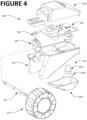
- the vehicle wheel balancing system 100 is provided with a non-contact measurement system 300 shown in Figure 4 , to acquire measurement data associated with the inboard surfaces 202 of a wheel assembly secured on the spindle shaft 102.
- the non-contact measurement system 300 includes a fixed receiver 302 having an optical detector 302a and associated optical elements 302b with a field of view, a laser emitter module 304 independently mounted in a rotational-sensor fixture 305 to a laser support shaft 306 for rotation about a longitudinal axis of the shaft 306, and control circuits 308 for operating the laser emitter and optical detector.
- the fixed receiver 302 and laser emitter module 304 may optionally be supported by a common mounting bracket 310 contained within upper and lower covers 310a, 310b, secured to the base or tub 102 in proximity to the spindle shaft 104, or may be mounted to the base or tub separately.
- the laser emitter module 304 When activated, the laser emitter module 304 is rotatable about an axis of the laser support shaft 306 to emit a laser beam 312a within an emission plane orthogonal to the rotational axis of the support shaft 306. Laser light 312b reflected from illuminated surfaces within the emission plane is observable within the field of view of the optical detector 302a.
- An adjustment knob 314 disposed adjacent to an external surface of the base or tub 102 is operatively coupled to the laser emitter module 304 to enable manual rotation of the laser emitter module about the support shaft axis 306.
- an operator orients the emitted laser beam 312a within the emission plane to illuminate a desired location on a surface of the wheel assembly, such as the inboard surface 202.
- a drive motor may be coupled to the laser emitter module 304 and controlled by the wheel balancer processor to selectively rotate the laser emitter module 304 about the axis of the support shaft 306, directing the emitted laser 312a to illuminate specific locations on the wheel assembly inboard surface 202, or sweeping the emitted laser beam 312a across a portion of the wheel assembly to scan a contour of the surfaces.
- the various components for rotating the laser emitter module 304 are configured such that once the laser emitter module 304 is rotated to emit the laser beam 312a at a desired orientation towards the wheel assembly surface 202, the laser emitter module 304 will remain at that orientation until subsequently moved by an intentional action (such as by manual rotation of the adjustment knob 314 or engagement of the drive motor if so configured).
- Laser light 312b reflected from the illuminated surfaces is filtered and/or focused by the optical elements 302b onto, and received by, the optical detector 302a of the fixed receiver 302.
- the focused reflected light forms an illuminated spot on a light-sensitive surface of the optical detector 302a, illuminating a cluster of light-receiving elements or pixels.
- Control circuits 308 process the light intensity data from these illuminated pixels to calculate a spatial location of a centroid for the illuminated spot on the surface of the optical detector 302a in pixel coordinates.
- an operator rotates the adjustment knob 314 to direct the laser beam 312a to illuminates a desired point on a wheel assembly surface, such as an intended placement plane for an imbalance correction weight on the inboard surface 202 or a wheel rim edge 208.
- Orientation of the laser emitter 304 about the axis of the support shaft 306 is tracked by means of a rotary encoder or other suitable rotational position sensor fixture 305, which generates a representative rotational position output signal for communication to the control logic 308 or processor of the wheel balancer system 100.
- the operator presses a button or actuates a foot pedal to signal the sensor module 300 to process the output of the fixed optical detector 302 and generate an output signal to the wheel balancer control logic which is representative of an angular orientation within the emission plane along which the reflected laser light 312b was received at the optical detector 302a, i.e., the incident angle.
- the generated output signal is an analog voltage signal which varies between bounding limits, such as 0.0 and 5.0 volts, in proportion to a location of centroid in at least one pixel dimension on the surface of the optical detector 302a.
- the form of the output signal generated for conveyance to the wheel balancer control logic may be in any format suitable for conveying the centroid location, including a proportional digital signal, direct numerical coordinate representation, etc.
- the specific relationship between the generated output signal and the angular orientation may be established by calibration to test surfaces at known distances, with one or more calibration factors stored for use by the control logic or processor of the wheel balancer system 100.
- the vehicle wheel balancing system 100 includes a protective hood structure 108 coupled to the base 102 by a support tube 104 which is configured for arcuate movement about a hood axis by a pivot assembly 112 including a rotational position sensor.
- a protective hood structure 108 and support tube 110 transitions through a range of movement between a raised position clear of the wheel assembly 200 secured to the spindle shaft 104, as shown in Figure 1 , and a lowered position partially enclosing the wheel assembly 200.
- a second non-contact measurement system 400 is disposed on the support tube 110 within a protective enclosure 402 to acquire measurement data associated with the outboard surfaces 204 of the wheel assembly 200.
- the second non-contact measurement system 400 includes a fixed laser emitter module 404, a fixed optical receiver 406 having an optical detector and associated lens assembly with a field of view, and control circuits 408 for operating the laser emitter 404 and optical detector 406.
- the laser emitter module, optical detector, and control circuits may be commonly mounted to a framework 410 enclosed within an upper cover 410a and lower cover 41 0b, and secured within the protective enclosure 402 secured to the support tube 110, or may be independently mounted there on.
- the outer sensor 400 is functionally similar to the first (inner) non-contact measurement system 300 for acquiring measurement data from the inboard surfaces 202 of the wheel assembly 200.
- the laser emitter module 404 When activated, the laser emitter module 404 emits a laser beam 414 towards the wheel assembly as best seen in Figure 3 .
- a radial distance of the emitted laser beam 414 from the axis of the spindle shaft 104 is dependent upon the current rotational position of the hood structure about the hood axis, as illustrated in Figure 6 .
- the hood rotational position is monitored by a Hall-effect sensor or other suitable rotational position sensor coupled to the support shaft 104 in the pivot assembly 112, and configured to send a rotational position output signal to the control logic or processor for the wheel balancing system 100.
- the focused reflected light forms an illuminated spot on a light sensitive surface of the optical detector 406, illuminating a cluster of light-receiving elements or pixels.
- the outer sensor control circuits 408 process the light intensity data from these illuminated pixels to calculate a spatial location of a centroid for the illuminated spot on the surface of the optical detector 406 in pixel coordinates.
- the optical path of laser light 414 reflected from the illuminated laser spot on the wheel assembly surface varies only with changes in the laser travel distance to the illuminated surface, altering the incident angle at which the reflected laser light is received at the optical detector 406, and hence the pixel coordinates for the calculated centroid location for the spot of reflected light on the optical detector light sensitive surface.
- Observations of the incident angle for the laser light 414 reflected to the imaging sensor of the outer sensor 400 are processed by the control logic or processor of the wheel balancing system 400, together with the output signal representing the rotational position of the protective hood 108, to triangulate a distance from the outer sensor 400 to the illuminated point on the outer surface 204 of the wheel assembly 200.
- the observations may be acquired over a range of arcuate movement for the protective hood structure 108, establishing a contour of the wheel assembly outer surface 204, or may be acquired when the protective hood structure 108 is disposed at a selected angular orientation, establishing a distance to a specific location on the wheel assembly outer surface 204 at a known radius from the axis of the spindle shaft 104, such as an outer wheel rim edge 208 for corresponding to an installation plane for an outer clip-style imbalance correction weight.
- the inboard non-contact sensor module 300 is first utilized by the operator to identify the inboard wheel rim edge 208 with the laser emitter 304, establishing the location of the inboard imbalance correction plane and the wheel rim edge radius.
- the second (or outer) non-contact sensor module 400 is automatically activated to acquire a distance measurement when the projection axis of laser 414 is at the measured radius for the inner wheel rim edge 208, thereby establishing the location of the outer wheel rim edge and outboard imbalance correction plane, and correspondingly, a width of the wheel rim 200 (or separation distance between in the inboard and outboard imbalance correction planes).
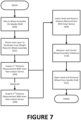
- a method for operating the wheel balancing system of the present disclosure is illustrated by the flow chart of Figure 7 .
- a wheel assembly 200 is mounted to the balancer spindle shaft 104 (Box 500).
- the operator next (at Box 502) rotates the adjustment knob 314 for the laser module 304 of the inner non-contact sensor module 300 to orient the emitted laser beam 312a to illuminate an inner or first weight plane on an inner surface 202 of the wheel assembly 200 for use with either an adhesive or clip-on imbalance correction weight.
- the operator triggers acquisition of a first distance measurement (Box 504).
- the operator may again rotate the adjustment knob 314 to orient the emitted laser 312a to illuminate a second weight plane on the inner surface 202 of the wheel assembly 200 for use with an adhesive imbalance correction weight, and again trigger acquisition of a distance measurement.
- the protective hood structure 108 is lowered (Box 508), and a distance measurement to the outer surface 204 of the wheel assembly 200 is acquired using the outer non-contact sensor module 400 as the hood movement traverses an arc across the wheel rim edge 208 transition between tire and wheel rim.
- the distance measurement from the outer non-contact sensor module defines a wheel rim width dimension, and an outer imbalance correction weight plane for use with a clip-on imbalance correction weight.
- the wheel balancer control logic may utilize information obtained from the inner and outer non-contact sensor modules 300, 400 to provide warnings to an operator during operation of the wheel balancer system 100. For example, since the laser emitter 304 of the inner sensor module 300 remains oriented towards the wheel assembly 200 inner surface 202 until changed by an operator, data from the inner sensor module 300 may be utilize as illustrated in the flow chart of Fig. 8 to warn an operator if measurement of a wheel dimension has not been completed before attempting to measure an imbalance in the wheel assembly 200.
- the wheel balancer control logic may be configured with suitable software instructions to compare a "last measured” distance based on data from the inner sensor module 300 with a "current" distance before activating a drive motor to rotate the spindle shaft 104 and a wheel assembly 200 mounted there on. If the comparison indicates a change in distance exceeding an acceptable tolerance, it is likely a new wheel assembly 200 has been mounted to the spindle shaft 104, and a new set of measurements should be acquired.
- an exemplary implementation of this process may include the following steps:
- Distance measurements acquired by the inner and outer non-contact sensor modules 300, 400 may be utilized to provide additional functionality to the wheel balancer system 100.
- the control logic of the wheel balancer system 100 is configured with software instructions to acquire periodic measurements of distance from the inner non-contact sensor module 300
- removal of a wheel assembly 200 previously secured to the spindle shaft 104 can be detected by identifying a significant change in the measured distance without any accompanying change in the orientation of the laser emitter 304. This change is a result of the wheel assembly 200 having been removed from the spindle shaft 104, such that the emitter laser 312a strikes the floor or some other distant surface instead of the wheel assembly inner surface 202.
- the control logic of the wheel balancer system 100 may be configured with software instructions to detect a miss-centered mounting of the wheel assembly 200 or an out-of-round damage condition for the wheel assembly.
- the inner laser emitter 304 oriented to illuminate a point on the wheel assembly inner surface 202
- periodic distance measurements are acquired as the wheel assembly 200 is rotated about the axis of the spindle shaft 104. Changes in the periodic distance measurements, without any accompanying changes in an orientation of the laser emitter 304, such as by rotation of the adjustment knob 314, are indicative of either a miss-centered mounting or potential wheel rim damage due to an out-of-round condition.
- the wheel balancer system may be configured to provide the operator with a suitable warning.
- the laser emitter 304 of the inner non-contact sensor 300 may be utilized to aid an operator in proper placement of an imbalance correction weight on the wheel assembly surface 202.
- the control logic for the wheel balancer 100 may be configured with software instructions to calculate one or more imbalance correction weight amounts for placement at specific rotational and axial positions about the wheel assembly 200 as is convention in the art. The operator is responsible for applying the correct amount of imbalance correction weight at the required locations.
- the control logic for the wheel balancer system 100 can be configured with software instructions to control the rotational position of the wheel assembly 200 on the axis of the spindle shaft 104, and to rotate the wheel assembly 200 such that the axial plane in which an imbalance correction weight is to be applied to the wheel assembly 200 is aligned with the emission plane of the inner laser emitter 304, such that a laser beam 312a projected from the laser emitter 304, at the correct orientation, will strike the inner surface 202 of the wheel assembly 200 at a location for placement of an imbalance correction weight.
- the control logic can automatically rotate the laser emitter 304 to the correct orientation at which to project the emitted the laser beam 312a.
- the control logic may be configured to provide the operator with visual guidance for rotating the adjustment knob 314 to orient the laser emitter 304 at the correct orientation to illuminate the weight placement location.
- the laser emitter 304 may be controlled to pulse the laser 312a at a varying rate proportional to the orientation at which the beam is emitted. A faster pulse indicates the orientation is near the target, while a slower pulse indicates it is further from the target.
- the laser emitter 304 may be controlled to emit the laser beam 312a in a steady-state configuration, illuminating the desired placement location on the wheel assembly inner surface 202. It will of course, be recognized that variety of other methods may be utilized to aid the operator in adjusting an orientation of the laser emitter 304 to align with a placement location on the wheel assembly 200 for an imbalance correction weight.
- a review of the distance measurements acquired by the inner non-contact sensor module 300 in response to operator input commands can be utilized by the control logic of the wheel balancer system 100 to identify the particular mode of imbalance correction intended by the operator.
- Modes of imbalance correction can include a clip-clip mode, a tape-tape mode, or a clip-tape mode, with "clip” or “tape” referring to the type of imbalance correction weight to be installed on the wheel assembly 200 at the inner and outer imbalance correction planes.
- clip-clip mode the operator will only be required to utilize the inner non-contact sensor module 300 to designate a single imbalance correction weight location, i.e., the inner wheel rim edge 208.
- the outer weight placement location will be measured automatically during the lowering of the protective hood structure 108, at the same radial dimension as identified with the inner non-contact sensor module 300.
- imbalance weights will be placed in two different imbalance correction planes on the inboard side of the wheel assembly 200, necessitating acquisition of two different measurements from the inboard non-contact sensor module 300.
- weights With a tape-tape mode, weights will be placed on the inner surfaces 202 of the wheel rim 208, at two different axial positions, and will likely be at similar radial dimensions.
- control logic of the wheel balancer system 100 may be configured with software instructions to detect when two sequential measurements from the inner non-contact sensor module 300, at different orientations of the laser emitter 304, identify locations on the wheel rim surface 202 having similar radial dimensions, and thereby automatically select the tape-tape imbalance correction mode.
- the control logic of the wheel balancer system 100 may be configured to detect when two sequential measurements from the inner non-contact sensor module 300, at different orientations of the laser emitter 304, identify locations on the wheel assembly 200 having radial dimensions which differ by more than a limit, and thereby automatically select the clip-tape imbalance correction mode.
- inner and outer sensor module distance measurement data may be utilized to achieve a variety of additional functions for the wheel balancer system 100, similar to features and functionality obtained using measurements of a wheel assembly obtained from traditional mechanical dataset arms.
- the outer non-contact sensor module 400 consists of a fixed laser emitter 404 in conjunction with a fixed optical detector 406
- fixed laser emitter 404 may be replaced by a laser emitter configured for rotation about at least one axis, similar to laser emitter 304, either under manual or automated control.
- the fixed laser emitter 404 may be replaced by gimbal-mounted laser emitter configured for rotational movement about at least one axis of rotation in response to commands from the control logic of the wheel balancer system 100.
- Providing rotational movement of the laser emitter 404 in the outer non-contact sensor module 400 provides a means by which the emitted laser beam 414 may be selectively positioned or swept across outer surfaces 204 of the wheel assembly 200 without the need to rotate or reposition the protective hood structure 108.
- the present disclosure can be embodied in-part in the form of computer-implemented processes and apparatuses for practicing those processes.
- the present disclosure can also be embodied in-part in the form of computer program code containing instructions embodied in tangible media, or another computer readable non-transitory storage medium, wherein, when the computer program code is loaded into, and executed by, an electronic device such as a computer, micro-processor or logic circuit, the device becomes an apparatus for practicing the present disclosure.
- the present disclosure can also be embodied in-part in the form of computer program code, for example, whether stored in a non-transitory storage medium, loaded into and/or executed by a computer, or transmitted over some transmission medium, wherein, when the computer program code is loaded into and executed by a computer, the computer becomes an apparatus for practicing the present disclosure.
- the computer program code segments configure the microprocessor to create specific logic circuits.
Landscapes
- Physics & Mathematics (AREA)
- General Physics & Mathematics (AREA)
- Testing Of Balance (AREA)
- Length Measuring Devices By Optical Means (AREA)
Claims (16)
- Système d'équilibrage de roue ayant une structure de base (102) supportant un arbre de broche (104) pour recevoir de manière coaxiale un ensemble roue de véhicule (200), un appareil mesurant par voie optique l'ensemble roue de véhicule (200), et un processeur configuré pour faire fonctionner le système d'équilibrage de roue (100) ; comprenant :un capteur sans contact (300) fixé à la structure de base (102), ledit capteur sans contact (300) comprenant un premier capteur optique fixe (302), une première logique de commande (308) et un premier émetteur laser (304) monté sur un arbre de support de laser (306) pour un mouvement de rotation indépendant dudit premier capteur optique fixe (302), ledit premier émetteur laser (304) étant aligné pour projeter un faisceau laser (312a) vers une surface intérieure (202) de l'ensemble roue de véhicule (200) ; etun mécanisme de réglage (314) couplé de manière fonctionnelle audit premier émetteur laser (304) pour faire tourner ledit premier émetteur laser autour d'un axe dudit arbre de support (306), dans lequel une orientation du faisceau laser (312a) dans un plan d'émission est sensible à une position de rotation dudit premier émetteur laser (304) ;un capteur de position de rotation (305) associé audit premier émetteur laser (304), ledit capteur de position de rotation (305) étant configuré pour générer un second signal de sortie vers ledit processeur, ledit second signal de sortie étant représentatif d'une position de rotation dudit premier émetteur laser (304) autour d'un axe dudit arbre de support de laser (306) ;dans lequel ladite première logique de commande (308) est configurée pour recevoir une sortie provenant dudit premier capteur optique fixe (302) en réponse à une position de pixel sur une surface photosensible dudit premier capteur optique fixe (302) éclairé par un premier spot de lumière réfléchie (312b) par un point sur ladite surface intérieure (202) éclairé par ledit premier faisceau laser (312a) dans ledit plan d'émission ; etdans lequel ladite première logique de commande (308) est configurée en outre pour utiliser et ladite sortie provenant dudit premier capteur optique fixe (302) pour générer vers ledit processeur un signal de sortie qui est représentatif d'un angle d'incidence dans ledit plan d'émission le long duquel ledit premier spot de lumière laser réfléchie (312b) est reçu au niveau d'un détecteur optique (302a) depuis ladite surface intérieure (202).
- Système selon la revendication 1, dans lequel ladite première logique de commande (308) est sensible à un signal d'entrée déclenché par un opérateur pour générer ledit signal de sortie représentatif dudit angle d'incidence.
- Système selon la revendication 1, dans lequel ledit mécanisme de réglage (314) est un bouton de réglage actionnable manuellement.
- Système selon la revendication 1, dans lequel ledit mécanisme de réglage (314) comprend un moteur d'entraînement sensible à une sortie provenant dudit processeur pour modifier une orientation dudit premier émetteur laser (314) autour dudit axe de l'arbre de support de laser (306).
- Système selon la revendication 1, dans lequel le système d'équilibrage de roue (100) comprend en outre une structure de capot de protection (108) fixée à la structure de base (102) sur un arbre de support de capot (110) pour un mouvement arqué autour d'un axe de capot entre une position ouverte dégagée de l'ensemble roue de véhicule (200) et une position fermée enfermant partiellement l'ensemble roue de véhicule (200) ; comprenant en outre :un capteur extérieur sans contact (400) fixé à la structure de capot de protection (108), ledit capteur extérieur sans contact (400) comprenant un second capteur optique fixe (406), une seconde logique de commande (408) et un second émetteur laser (404), ledit second émetteur laser étant fixé pour projeter un second faisceau laser (414) vers une surface extérieure (204) de l'ensemble roue de véhicule (200) ; etun capteur de position de rotation (112) associé à la structure de capot de protection (108), ledit capteur de position de rotation (112) étant configuré pour générer un signal de sortie de position de capot vers ledit processeur représentatif d'une position de rotation de l'arbre de support de capot (110) autour dudit axe de capot ;dans lequel ladite seconde logique de commande (408) est configurée pour recevoir une sortie provenant dudit second capteur optique fixe (406) en réponse à une position de pixel sur une surface photosensible dudit second capteur optique fixe (406) pour un second spot de lumière laser réfléchie par un point sur ladite surface extérieure (204) éclairé par ledit second faisceau laser (414) ; etdans lequel ladite seconde logique de commande (408) est configurée en outre pour utiliser ladite sortie provenant dudit second capteur optique fixe (406) conjointement avec une sortie provenant dudit capteur de position de rotation (112) représentative d'une position de rotation associée de la structure de capot de protection (108) autour dudit arbre de support de capot (110), pour générer un second signal de sortie vers ledit processeur qui est représentatif d'un angle d'incidence au niveau dudit second capteur optique fixe (406) pour ladite lumière laser réfléchie depuis ladite surface extérieure (204).
- Système selon la revendication 5, dans lequel ladite première logique de commande (308) est sensible à un signal d'entrée déclenché par un opérateur pour générer ledit premier signal de sortie représentatif dudit angle d'incidence de ladite lumière réfléchie par ladite surface intérieure (202) ; et
dans lequel ladite seconde logique de commande (408) est sensible à un signal d'entrée déclenché par un processeur pour générer ledit second signal de sortie représentatif dudit angle d'incidence de ladite lumière réfléchie par ladite surface extérieure (204). - Système selon la revendication 6, dans lequel ledit signal d'entrée déclenché par un processeur est associé à ladite position de rotation de l'arbre de support de capot (110) autour dudit axe de capot.
- Système d'équilibrage de roue ayant une structure de base (102) supportant un arbre de broche (104) pour recevoir de manière coaxiale un ensemble roue de véhicule (200), un appareil mesurant par voie optique l'ensemble roue de véhicule (200), une structure de capot de protection (108) fixée à la structure de base (102) sur un arbre de support (110) pour un mouvement arqué autour d'un axe de capot entre une position ouverte dégagée de l'ensemble roue de véhicule (200) et une position fermée enfermant partiellement l'ensemble roue de véhicule (200), et un processeur configuré pour faire fonctionner le système d'équilibrage de roue (100) ; comprenant :un capteur sans contact (400) fixé à la structure de capot de protection (108), ledit capteur sans contact (400) comprenant un capteur optique fixe (406) et un émetteur laser fixe (404) orienté pour projeter un faisceau laser (414) vers une surface extérieure (204) de l'ensemble roue de véhicule (200) pendant ledit mouvement arqué de la structure de capot de protection (108) ;un capteur de position de rotation (112) associé à ladite structure de capot de protection (108), ledit capteur de position de rotation (112) étant configuré pour générer un signal de sortie de position de capot vers ledit processeur représentatif d'une position de rotation de l'arbre de support de capot (110) autour dudit axe de capot ;une logique de commande (408) associée audit capteur sans contact (400), ladite logique de commande (408) étant configurée pour recevoir une sortie provenant dudit capteur optique fixe (406) en réponse à une position de pixel sur une surface photosensible dudit capteur optique fixe (406) d'un spot de lumière laser réfléchi par un point sur ladite surface extérieure (204) éclairé par ledit faisceau laser (414) pendant ledit mouvement arqué de la structure de capot de protection (108) ;dans lequel ladite logique de commande (408) est configurée en outre pour utiliser ladite sortie provenant dudit capteur optique fixe (406) pour générer un signal de sortie vers ledit processeur qui est représentatif d'un angle d'incidence au niveau dudit capteur optique fixe (406) pour ladite lumière laser réfléchie par ladite surface extérieure (204) ; etdans lequel ledit processeur est configuré pour utiliser ledit signal de sortie de position de capot et ledit signal de sortie représentatif dudit angle d'incidence pour trianguler une distance allant dudit capteur sans contact (400) jusqu'audit point éclairé sur ladite surface extérieure (204).
- Procédé de mesure optique d'un ensemble roue de véhicule (200) reçu de manière coaxiale sur un arbre de broche (104) d'un système d'équilibrage de roue (100) selon la revendication 1, le procédé comprenant les étapes suivantes :fournir un capteur de mesure interne sans contact (300) sur une structure de base (102) du système d'équilibrage de roue (100) pour acquérir des mesures à partir d'une surface intérieure (202) de l'ensemble roue de véhicule (200), ledit capteur de mesure interne sans contact (300) comprenant un émetteur laser (304) monté sur un arbre de support de laser (306) pour faire tourner et émettre un faisceau laser (312a) dans un plan d'émission croisant ladite surface intérieure (202), et un récepteur fixe ayant un détecteur optique (302) sensible à la lumière laser réfléchie (312b) reçue au niveau d'une surface photosensible du détecteur optique (302) et réfléchie par ladite surface intérieure (202) pour identifier un angle d'incidence de ladite lumière laser réfléchie (312b) ;fournir un capteur de position de rotation (305) configuré pour générer un signal de sortie représentatif d'une position de rotation de l'émetteur laser (304) autour d'un axe dudit arbre de support de laser (306) ; etdéterminer, en utilisant ledit angle d'incidence identifié de la lumière laser réfléchie au niveau dudit récepteur fixe et ledit signal de sortie de capteur de position de rotation, au moins une distance linéaire allant dudit capteur de mesure sans contact (300) jusqu'à un point sur ladite surface intérieure (202) éclairé par ledit faisceau laser émis (312a).
- Procédé selon la revendication 9, dans lequel ladite au moins une distance linéaire est un déplacement radial dudit point éclairé sur ladite surface intérieure (202) à partir d'un axe de l'arbre de broche (104).
- Procédé selon la revendication 9, comprenant en outre l'étape consistant à faire tourner manuellement ledit émetteur laser (304) autour dudit axe de l'arbre de support de laser (306) pour éclairer un point sélectionné sur ladite surface intérieure (202) de l'ensemble roue du véhicule (200).
- Procédé selon la revendication 11, dans lequel ledit point sélectionné est situé sur un bord de jante intérieur (208) de l'ensemble roue de véhicule (200).
- Procédé selon la revendication 11, dans lequel ledit point sélectionné est situé dans un plan de correction de déséquilibre de l'ensemble roue de véhicule (200).
- Procédé selon la revendication 9, comprenant en outre :fournir un capteur de mesure externe sans contact (400) sur une structure de capot de protection (108) du système d'équilibrage de roue (100) pour acquérir des mesures à partir d'une surface extérieure (204) de l'ensemble roue de véhicule (100), ledit capteur de mesure externe sans contact (400) comprenant un émetteur laser fixe (404) pour émettre un faisceau laser (414) vers ladite surface extérieure (204), et un détecteur optique stationnaire (406) sensible à la lumière laser réfléchie (312b) reçue au niveau d'une surface photosensible du détecteur optique stationnaire (406) depuis ladite surface extérieure (204) pour identifier un angle d'incidence de ladite lumière laser réfléchie (312b) ; etdéterminer, en utilisant ledit angle d'incidence identifié de la lumière laser réfléchie depuis ladite surface extérieure (204), et une configuration connue dudit capteur de mesure externe sans contact (400), au moins une distance linéaire associée à un point sur ladite surface extérieure (204) éclairé par ledit faisceau laser émis (414).
- Procédé selon la revendication 14, comprenant en outre :fournir un second capteur de position de rotation (112) configuré pour générer un signal de sortie représentatif d'une position de rotation de la structure de capot de protection (108) autour d'un axe d'un arbre de support de capot (110) ;dans lequel ladite étape de détermination de ladite au moins une distance linéaire associée à un point sur ladite surface extérieure (204) est sensible audit signal de sortie représentatif de ladite position de rotation de la structure de capot de protection (108) indiquant que ledit émetteur laser fixe (404) dudit capteur de position de rotation externe (400) est positionné pour émettre ledit faisceau laser (414) le long d'un axe à une distance radiale sélectionnée à partir d'un axe dudit arbre de broche (104).
- Procédé selon la revendication 15, dans lequel ladite distance radiale sélectionnée est identifiée par un opérateur utilisant ledit capteur de mesure interne sans contact (300) pour éclairer un point sur ladite surface intérieure (202) de l'ensemble roue de véhicule (200).
Applications Claiming Priority (2)
| Application Number | Priority Date | Filing Date | Title |
|---|---|---|---|
| US201762554214P | 2017-09-05 | 2017-09-05 | |
| PCT/US2018/049176 WO2019050799A1 (fr) | 2017-09-05 | 2018-08-31 | Système d'équilibrage de roues avec capteurs de mesure montés sur capot |
Publications (3)
| Publication Number | Publication Date |
|---|---|
| EP3679319A1 EP3679319A1 (fr) | 2020-07-15 |
| EP3679319C0 EP3679319C0 (fr) | 2024-05-29 |
| EP3679319B1 true EP3679319B1 (fr) | 2024-05-29 |
Family
ID=63684514
Family Applications (1)
| Application Number | Title | Priority Date | Filing Date |
|---|---|---|---|
| EP18778681.9A Active EP3679319B1 (fr) | 2017-09-05 | 2018-08-31 | Système d'équilibrage de roues avec capteurs de mesure montés sur capot |
Country Status (3)
| Country | Link |
|---|---|
| US (1) | US11015920B2 (fr) |
| EP (1) | EP3679319B1 (fr) |
| WO (1) | WO2019050799A1 (fr) |
Families Citing this family (7)
| Publication number | Priority date | Publication date | Assignee | Title |
|---|---|---|---|---|
| US10794789B2 (en) | 2016-02-09 | 2020-10-06 | Carlo Buzzi | Method and machine for balancing a vehicle wheel |
| KR102633349B1 (ko) * | 2018-03-02 | 2024-02-06 | 빅 다이쇼와 가부시키가이샤 | 회전 공구의 밸런스 및 오실레이션 조정 시스템, 밸런스 및 오실레이션 계측 장치, 밸런스 및 오실레이션 조정 방법, 및 공구 홀더 |
| JP7220690B2 (ja) * | 2020-09-17 | 2023-02-10 | 北海道電力株式会社 | 回転軸の振れ見測定システム、制御装置及び振れ見測定方法 |
| IT202100018713A1 (it) | 2021-07-16 | 2023-01-16 | Snap On Equip Srl Unico Socio | Metodo e apparato per determinare le dimensioni geometriche di una ruota |
| JP7282299B1 (ja) | 2021-12-28 | 2023-05-29 | 小野谷機工株式会社 | ホイールバランサ測定装置 |
| JP7503859B1 (ja) | 2022-12-16 | 2024-06-21 | 小野谷機工株式会社 | ホイールバランス測定装置 |
| USD1113521S1 (en) * | 2024-06-26 | 2026-02-17 | Hunter Engineering Company | Hood for a wheel balancing system |
Citations (2)
| Publication number | Priority date | Publication date | Assignee | Title |
|---|---|---|---|---|
| US20130128281A1 (en) * | 2010-07-30 | 2013-05-23 | Sicam S.R.L. | Method for detecting the shape and/or dimensions of a wheel on vehicle repair workshop machines or the like |
| US20170091922A1 (en) * | 2014-05-05 | 2017-03-30 | Hexagon Technology Center Gmbh | Surveying system |
Family Cites Families (7)
| Publication number | Priority date | Publication date | Assignee | Title |
|---|---|---|---|---|
| US5189912A (en) * | 1988-09-07 | 1993-03-02 | Interbalco Ag | Ultrasonic wheel measuring apparatus and wheel balancer incorporating same |
| EP0925489B9 (fr) * | 1996-09-06 | 2007-11-21 | Snap-On Equipment Europe Limited | Machine a equilibrer les roues |
| US7355687B2 (en) * | 2003-02-20 | 2008-04-08 | Hunter Engineering Company | Method and apparatus for vehicle service system with imaging components |
| US7199873B2 (en) * | 2004-01-27 | 2007-04-03 | Snap-On Equipment Srl A Unico Socio | Method and apparatus for balancing a motor vehicle wheel |
| IT1393375B1 (it) * | 2008-09-12 | 2012-04-20 | Sicam Srl | Macchina equilibratrice per l'equilibratura di ruote di veicoli |
| ITTO20120540A1 (it) * | 2012-06-20 | 2013-12-21 | M & B Engineering S R L | Macchina e metodo per l'equilibratura delle ruote di un veicolo |
| US10794789B2 (en) * | 2016-02-09 | 2020-10-06 | Carlo Buzzi | Method and machine for balancing a vehicle wheel |
-
2018
- 2018-08-31 EP EP18778681.9A patent/EP3679319B1/fr active Active
- 2018-08-31 WO PCT/US2018/049176 patent/WO2019050799A1/fr not_active Ceased
- 2018-08-31 US US16/642,761 patent/US11015920B2/en active Active
Patent Citations (2)
| Publication number | Priority date | Publication date | Assignee | Title |
|---|---|---|---|---|
| US20130128281A1 (en) * | 2010-07-30 | 2013-05-23 | Sicam S.R.L. | Method for detecting the shape and/or dimensions of a wheel on vehicle repair workshop machines or the like |
| US20170091922A1 (en) * | 2014-05-05 | 2017-03-30 | Hexagon Technology Center Gmbh | Surveying system |
Also Published As
| Publication number | Publication date |
|---|---|
| EP3679319C0 (fr) | 2024-05-29 |
| WO2019050799A1 (fr) | 2019-03-14 |
| EP3679319A1 (fr) | 2020-07-15 |
| US20200191561A1 (en) | 2020-06-18 |
| US11015920B2 (en) | 2021-05-25 |
Similar Documents
| Publication | Publication Date | Title |
|---|---|---|
| EP3679319B1 (fr) | Système d'équilibrage de roues avec capteurs de mesure montés sur capot | |
| CN101358839B (zh) | 确定车轮几何尺寸的方法和设备 | |
| CN101055232B (zh) | 光学扫描车轮的充气轮胎胎面的方法 | |
| US7355687B2 (en) | Method and apparatus for vehicle service system with imaging components | |
| US7466430B2 (en) | Method and apparatus for optically scanning a pneumatic tire of a vehicle wheel | |
| EP2332749B1 (fr) | Procédé et appareil pour déterminer la dimension géométrique d'une roue de véhicule avec des capteurs optiques | |
| US8113049B2 (en) | Method and a machine for balancing vehicle wheels | |
| US6535281B2 (en) | Method and apparatus for optically scanning a vehicle wheel | |
| US7735367B2 (en) | Vehicle wheel balancer system with projection display | |
| US10605600B2 (en) | Surveying system | |
| NL9100127A (nl) | Wielbalanceerinrichting, uitloopmeetinrichting, inrichting voor het bepalen van de fysieke configuratie van een lichaam, en werkwijze voor het bepalen van fysische kenmerken van een lichaam. | |
| JP6653028B2 (ja) | レーザー受信機に入射する受信ビームと回転レーザービームとを比較するための方法 | |
| EP3629056A1 (fr) | Alignement de capteur de détection d'objets | |
| US10267659B2 (en) | Angle detecting device and surveying instrument | |
| US20210080578A1 (en) | Three-dimensional survey apparatus, three-dimensional survey method, and three-dimensional survey program | |
| US20150185106A1 (en) | Machine and method for balancing the wheels of a vehicle | |
| CN110332898A (zh) | 轮毂内径的检测系统及方法 | |
| CN112834174A (zh) | 镜头光学品质检测装置 | |
| JP2004132975A (ja) | 回転本体、特に自動車のホイール用の釣合い試験機 | |
| JPWO2020184238A1 (ja) | 光学制御装置および、これを含むヘッドアップディスプレイ装置 | |
| JP3012050B2 (ja) | 位置検出方法および位置検出装置 | |
| JP2021135256A (ja) | 形状測定装置及び形状測定方法 | |
| JPH0319498B2 (fr) | ||
| JPH073331B2 (ja) | 非球面形状測定装置 |
Legal Events
| Date | Code | Title | Description |
|---|---|---|---|
| STAA | Information on the status of an ep patent application or granted ep patent |
Free format text: STATUS: UNKNOWN |
|
| STAA | Information on the status of an ep patent application or granted ep patent |
Free format text: STATUS: THE INTERNATIONAL PUBLICATION HAS BEEN MADE |
|
| PUAI | Public reference made under article 153(3) epc to a published international application that has entered the european phase |
Free format text: ORIGINAL CODE: 0009012 |
|
| STAA | Information on the status of an ep patent application or granted ep patent |
Free format text: STATUS: REQUEST FOR EXAMINATION WAS MADE |
|
| 17P | Request for examination filed |
Effective date: 20200228 |
|
| AK | Designated contracting states |
Kind code of ref document: A1 Designated state(s): AL AT BE BG CH CY CZ DE DK EE ES FI FR GB GR HR HU IE IS IT LI LT LU LV MC MK MT NL NO PL PT RO RS SE SI SK SM TR |
|
| AX | Request for extension of the european patent |
Extension state: BA ME |
|
| DAV | Request for validation of the european patent (deleted) | ||
| DAX | Request for extension of the european patent (deleted) | ||
| STAA | Information on the status of an ep patent application or granted ep patent |
Free format text: STATUS: EXAMINATION IS IN PROGRESS |
|
| 17Q | First examination report despatched |
Effective date: 20220630 |
|
| GRAP | Despatch of communication of intention to grant a patent |
Free format text: ORIGINAL CODE: EPIDOSNIGR1 |
|
| STAA | Information on the status of an ep patent application or granted ep patent |
Free format text: STATUS: GRANT OF PATENT IS INTENDED |
|
| INTG | Intention to grant announced |
Effective date: 20240307 |
|
| GRAS | Grant fee paid |
Free format text: ORIGINAL CODE: EPIDOSNIGR3 |
|
| GRAA | (expected) grant |
Free format text: ORIGINAL CODE: 0009210 |
|
| STAA | Information on the status of an ep patent application or granted ep patent |
Free format text: STATUS: THE PATENT HAS BEEN GRANTED |
|
| AK | Designated contracting states |
Kind code of ref document: B1 Designated state(s): AL AT BE BG CH CY CZ DE DK EE ES FI FR GB GR HR HU IE IS IT LI LT LU LV MC MK MT NL NO PL PT RO RS SE SI SK SM TR |
|
| REG | Reference to a national code |
Ref country code: CH Ref legal event code: EP |
|
| REG | Reference to a national code |
Ref country code: IE Ref legal event code: FG4D |
|
| REG | Reference to a national code |
Ref country code: DE Ref legal event code: R096 Ref document number: 602018070086 Country of ref document: DE |
|
| U01 | Request for unitary effect filed |
Effective date: 20240614 |
|
| U07 | Unitary effect registered |
Designated state(s): AT BE BG DE DK EE FI FR IT LT LU LV MT NL PT SE SI Effective date: 20240625 |
|
| U20 | Renewal fee for the european patent with unitary effect paid |
Year of fee payment: 7 Effective date: 20240827 |
|
| PG25 | Lapsed in a contracting state [announced via postgrant information from national office to epo] |
Ref country code: IS Free format text: LAPSE BECAUSE OF FAILURE TO SUBMIT A TRANSLATION OF THE DESCRIPTION OR TO PAY THE FEE WITHIN THE PRESCRIBED TIME-LIMIT Effective date: 20240929 |
|
| PG25 | Lapsed in a contracting state [announced via postgrant information from national office to epo] |
Ref country code: HR Free format text: LAPSE BECAUSE OF FAILURE TO SUBMIT A TRANSLATION OF THE DESCRIPTION OR TO PAY THE FEE WITHIN THE PRESCRIBED TIME-LIMIT Effective date: 20240529 |
|
| PG25 | Lapsed in a contracting state [announced via postgrant information from national office to epo] |
Ref country code: GR Free format text: LAPSE BECAUSE OF FAILURE TO SUBMIT A TRANSLATION OF THE DESCRIPTION OR TO PAY THE FEE WITHIN THE PRESCRIBED TIME-LIMIT Effective date: 20240830 |
|
| PG25 | Lapsed in a contracting state [announced via postgrant information from national office to epo] |
Ref country code: ES Free format text: LAPSE BECAUSE OF FAILURE TO SUBMIT A TRANSLATION OF THE DESCRIPTION OR TO PAY THE FEE WITHIN THE PRESCRIBED TIME-LIMIT Effective date: 20240529 |
|
| PG25 | Lapsed in a contracting state [announced via postgrant information from national office to epo] |
Ref country code: PL Free format text: LAPSE BECAUSE OF FAILURE TO SUBMIT A TRANSLATION OF THE DESCRIPTION OR TO PAY THE FEE WITHIN THE PRESCRIBED TIME-LIMIT Effective date: 20240529 |
|
| PG25 | Lapsed in a contracting state [announced via postgrant information from national office to epo] |
Ref country code: PL Free format text: LAPSE BECAUSE OF FAILURE TO SUBMIT A TRANSLATION OF THE DESCRIPTION OR TO PAY THE FEE WITHIN THE PRESCRIBED TIME-LIMIT Effective date: 20240529 Ref country code: NO Free format text: LAPSE BECAUSE OF FAILURE TO SUBMIT A TRANSLATION OF THE DESCRIPTION OR TO PAY THE FEE WITHIN THE PRESCRIBED TIME-LIMIT Effective date: 20240829 Ref country code: IS Free format text: LAPSE BECAUSE OF FAILURE TO SUBMIT A TRANSLATION OF THE DESCRIPTION OR TO PAY THE FEE WITHIN THE PRESCRIBED TIME-LIMIT Effective date: 20240929 Ref country code: HR Free format text: LAPSE BECAUSE OF FAILURE TO SUBMIT A TRANSLATION OF THE DESCRIPTION OR TO PAY THE FEE WITHIN THE PRESCRIBED TIME-LIMIT Effective date: 20240529 Ref country code: GR Free format text: LAPSE BECAUSE OF FAILURE TO SUBMIT A TRANSLATION OF THE DESCRIPTION OR TO PAY THE FEE WITHIN THE PRESCRIBED TIME-LIMIT Effective date: 20240830 Ref country code: ES Free format text: LAPSE BECAUSE OF FAILURE TO SUBMIT A TRANSLATION OF THE DESCRIPTION OR TO PAY THE FEE WITHIN THE PRESCRIBED TIME-LIMIT Effective date: 20240529 Ref country code: RS Free format text: LAPSE BECAUSE OF FAILURE TO SUBMIT A TRANSLATION OF THE DESCRIPTION OR TO PAY THE FEE WITHIN THE PRESCRIBED TIME-LIMIT Effective date: 20240829 |
|
| PG25 | Lapsed in a contracting state [announced via postgrant information from national office to epo] |
Ref country code: CZ Free format text: LAPSE BECAUSE OF FAILURE TO SUBMIT A TRANSLATION OF THE DESCRIPTION OR TO PAY THE FEE WITHIN THE PRESCRIBED TIME-LIMIT Effective date: 20240529 |
|
| PG25 | Lapsed in a contracting state [announced via postgrant information from national office to epo] |
Ref country code: SK Free format text: LAPSE BECAUSE OF FAILURE TO SUBMIT A TRANSLATION OF THE DESCRIPTION OR TO PAY THE FEE WITHIN THE PRESCRIBED TIME-LIMIT Effective date: 20240529 Ref country code: RO Free format text: LAPSE BECAUSE OF FAILURE TO SUBMIT A TRANSLATION OF THE DESCRIPTION OR TO PAY THE FEE WITHIN THE PRESCRIBED TIME-LIMIT Effective date: 20240529 |
|
| PG25 | Lapsed in a contracting state [announced via postgrant information from national office to epo] |
Ref country code: SM Free format text: LAPSE BECAUSE OF FAILURE TO SUBMIT A TRANSLATION OF THE DESCRIPTION OR TO PAY THE FEE WITHIN THE PRESCRIBED TIME-LIMIT Effective date: 20240529 |
|
| PG25 | Lapsed in a contracting state [announced via postgrant information from national office to epo] |
Ref country code: SM Free format text: LAPSE BECAUSE OF FAILURE TO SUBMIT A TRANSLATION OF THE DESCRIPTION OR TO PAY THE FEE WITHIN THE PRESCRIBED TIME-LIMIT Effective date: 20240529 Ref country code: SK Free format text: LAPSE BECAUSE OF FAILURE TO SUBMIT A TRANSLATION OF THE DESCRIPTION OR TO PAY THE FEE WITHIN THE PRESCRIBED TIME-LIMIT Effective date: 20240529 Ref country code: RO Free format text: LAPSE BECAUSE OF FAILURE TO SUBMIT A TRANSLATION OF THE DESCRIPTION OR TO PAY THE FEE WITHIN THE PRESCRIBED TIME-LIMIT Effective date: 20240529 Ref country code: CZ Free format text: LAPSE BECAUSE OF FAILURE TO SUBMIT A TRANSLATION OF THE DESCRIPTION OR TO PAY THE FEE WITHIN THE PRESCRIBED TIME-LIMIT Effective date: 20240529 |
|
| REG | Reference to a national code |
Ref country code: CH Ref legal event code: PL |
|
| PLBE | No opposition filed within time limit |
Free format text: ORIGINAL CODE: 0009261 |
|
| STAA | Information on the status of an ep patent application or granted ep patent |
Free format text: STATUS: NO OPPOSITION FILED WITHIN TIME LIMIT |
|
| PG25 | Lapsed in a contracting state [announced via postgrant information from national office to epo] |
Ref country code: MC Free format text: LAPSE BECAUSE OF FAILURE TO SUBMIT A TRANSLATION OF THE DESCRIPTION OR TO PAY THE FEE WITHIN THE PRESCRIBED TIME-LIMIT Effective date: 20240529 Ref country code: CH Free format text: LAPSE BECAUSE OF NON-PAYMENT OF DUE FEES Effective date: 20240831 |
|
| 26N | No opposition filed |
Effective date: 20250303 |
|
| PG25 | Lapsed in a contracting state [announced via postgrant information from national office to epo] |
Ref country code: IE Free format text: LAPSE BECAUSE OF NON-PAYMENT OF DUE FEES Effective date: 20240831 |
|
| U20 | Renewal fee for the european patent with unitary effect paid |
Year of fee payment: 8 Effective date: 20250827 |
|
| PGFP | Annual fee paid to national office [announced via postgrant information from national office to epo] |
Ref country code: GB Payment date: 20250827 Year of fee payment: 8 |
|
| PG25 | Lapsed in a contracting state [announced via postgrant information from national office to epo] |
Ref country code: CY Free format text: LAPSE BECAUSE OF FAILURE TO SUBMIT A TRANSLATION OF THE DESCRIPTION OR TO PAY THE FEE WITHIN THE PRESCRIBED TIME-LIMIT; INVALID AB INITIO Effective date: 20180831 |
|
| PG25 | Lapsed in a contracting state [announced via postgrant information from national office to epo] |
Ref country code: HU Free format text: LAPSE BECAUSE OF FAILURE TO SUBMIT A TRANSLATION OF THE DESCRIPTION OR TO PAY THE FEE WITHIN THE PRESCRIBED TIME-LIMIT; INVALID AB INITIO Effective date: 20180831 |