EP3679436B1 - Analyse de procédés sur lit de poudre - Google Patents
Analyse de procédés sur lit de poudre Download PDFInfo
- Publication number
- EP3679436B1 EP3679436B1 EP18793572.1A EP18793572A EP3679436B1 EP 3679436 B1 EP3679436 B1 EP 3679436B1 EP 18793572 A EP18793572 A EP 18793572A EP 3679436 B1 EP3679436 B1 EP 3679436B1
- Authority
- EP
- European Patent Office
- Prior art keywords
- predefined
- workpiece
- volume elements
- standard deviations
- moving average
- Prior art date
- Legal status (The legal status is an assumption and is not a legal conclusion. Google has not performed a legal analysis and makes no representation as to the accuracy of the status listed.)
- Active
Links
Images






Classifications
-
- G—PHYSICS
- G05—CONTROLLING; REGULATING
- G05B—CONTROL OR REGULATING SYSTEMS IN GENERAL; FUNCTIONAL ELEMENTS OF SUCH SYSTEMS; MONITORING OR TESTING ARRANGEMENTS FOR SUCH SYSTEMS OR ELEMENTS
- G05B19/00—Program-control systems
- G05B19/02—Program-control systems electric
- G05B19/418—Total factory control, i.e. centrally controlling a plurality of machines, e.g. direct or distributed numerical control [DNC], flexible manufacturing systems [FMS], integrated manufacturing systems [IMS] or computer integrated manufacturing [CIM]
- G05B19/41875—Total factory control, i.e. centrally controlling a plurality of machines, e.g. direct or distributed numerical control [DNC], flexible manufacturing systems [FMS], integrated manufacturing systems [IMS] or computer integrated manufacturing [CIM] characterised by quality surveillance of production
-
- B—PERFORMING OPERATIONS; TRANSPORTING
- B22—CASTING; POWDER METALLURGY
- B22F—WORKING METALLIC POWDER; MANUFACTURE OF ARTICLES FROM METALLIC POWDER; MAKING METALLIC POWDER; APPARATUS OR DEVICES SPECIALLY ADAPTED FOR METALLIC POWDER
- B22F10/00—Additive manufacturing of workpieces or articles from metallic powder
- B22F10/30—Process control
- B22F10/38—Process control to achieve specific product aspects, e.g. surface smoothness, density, porosity or hollow structures
-
- B—PERFORMING OPERATIONS; TRANSPORTING
- B22—CASTING; POWDER METALLURGY
- B22F—WORKING METALLIC POWDER; MANUFACTURE OF ARTICLES FROM METALLIC POWDER; MAKING METALLIC POWDER; APPARATUS OR DEVICES SPECIALLY ADAPTED FOR METALLIC POWDER
- B22F12/00—Apparatus or devices specially adapted for additive manufacturing; Auxiliary means for additive manufacturing; Combinations of additive manufacturing apparatus or devices with other processing apparatus or devices
- B22F12/90—Means for process control, e.g. cameras or sensors
-
- B—PERFORMING OPERATIONS; TRANSPORTING
- B29—WORKING OF PLASTICS; WORKING OF SUBSTANCES IN A PLASTIC STATE IN GENERAL
- B29C—SHAPING OR JOINING OF PLASTICS; SHAPING OF MATERIAL IN A PLASTIC STATE, NOT OTHERWISE PROVIDED FOR; AFTER-TREATMENT OF THE SHAPED PRODUCTS, e.g. REPAIRING
- B29C64/00—Additive manufacturing, i.e. manufacturing of three-dimensional [3D] objects by additive deposition, additive agglomeration or additive layering, e.g. by 3D printing, stereolithography or selective laser sintering
- B29C64/30—Auxiliary operations or equipment
- B29C64/386—Data acquisition or data processing for additive manufacturing
- B29C64/393—Data acquisition or data processing for additive manufacturing for controlling or regulating additive manufacturing processes
-
- B—PERFORMING OPERATIONS; TRANSPORTING
- B33—ADDITIVE MANUFACTURING TECHNOLOGY
- B33Y—ADDITIVE MANUFACTURING, i.e. MANUFACTURING OF THREE-DIMENSIONAL [3D] OBJECTS BY ADDITIVE DEPOSITION, ADDITIVE AGGLOMERATION OR ADDITIVE LAYERING, e.g. BY 3D PRINTING, STEREOLITHOGRAPHY OR SELECTIVE LASER SINTERING
- B33Y50/00—Data acquisition or data processing for additive manufacturing
- B33Y50/02—Data acquisition or data processing for additive manufacturing for controlling or regulating additive manufacturing processes
-
- G—PHYSICS
- G01—MEASURING; TESTING
- G01N—INVESTIGATING OR ANALYSING MATERIALS BY DETERMINING THEIR CHEMICAL OR PHYSICAL PROPERTIES
- G01N21/00—Investigating or analysing materials by the use of optical means, i.e. using sub-millimetre waves, infrared, visible or ultraviolet light
- G01N21/17—Systems in which incident light is modified in accordance with the properties of the material investigated
- G01N21/55—Specular reflectivity
-
- G—PHYSICS
- G05—CONTROLLING; REGULATING
- G05B—CONTROL OR REGULATING SYSTEMS IN GENERAL; FUNCTIONAL ELEMENTS OF SUCH SYSTEMS; MONITORING OR TESTING ARRANGEMENTS FOR SUCH SYSTEMS OR ELEMENTS
- G05B19/00—Program-control systems
- G05B19/02—Program-control systems electric
- G05B19/18—Numerical control [NC], i.e. automatically operating machines, in particular machine tools, e.g. in a manufacturing environment, so as to execute positioning, movement or co-ordinated operations by means of program data in numerical form
- G05B19/4097—Numerical control [NC], i.e. automatically operating machines, in particular machine tools, e.g. in a manufacturing environment, so as to execute positioning, movement or co-ordinated operations by means of program data in numerical form characterised by using design data to control NC machines, e.g. CAD/CAM
- G05B19/4099—Surface or curve machining, making three-dimensional [3D] objects, e.g. desktop manufacturing
-
- B—PERFORMING OPERATIONS; TRANSPORTING
- B22—CASTING; POWDER METALLURGY
- B22F—WORKING METALLIC POWDER; MANUFACTURE OF ARTICLES FROM METALLIC POWDER; MAKING METALLIC POWDER; APPARATUS OR DEVICES SPECIALLY ADAPTED FOR METALLIC POWDER
- B22F10/00—Additive manufacturing of workpieces or articles from metallic powder
- B22F10/20—Direct sintering or melting
- B22F10/28—Powder bed fusion, e.g. selective laser melting [SLM] or electron beam melting [EBM]
-
- B—PERFORMING OPERATIONS; TRANSPORTING
- B22—CASTING; POWDER METALLURGY
- B22F—WORKING METALLIC POWDER; MANUFACTURE OF ARTICLES FROM METALLIC POWDER; MAKING METALLIC POWDER; APPARATUS OR DEVICES SPECIALLY ADAPTED FOR METALLIC POWDER
- B22F10/00—Additive manufacturing of workpieces or articles from metallic powder
- B22F10/80—Data acquisition or data processing
- B22F10/85—Data acquisition or data processing for controlling or regulating additive manufacturing processes
-
- B—PERFORMING OPERATIONS; TRANSPORTING
- B29—WORKING OF PLASTICS; WORKING OF SUBSTANCES IN A PLASTIC STATE IN GENERAL
- B29C—SHAPING OR JOINING OF PLASTICS; SHAPING OF MATERIAL IN A PLASTIC STATE, NOT OTHERWISE PROVIDED FOR; AFTER-TREATMENT OF THE SHAPED PRODUCTS, e.g. REPAIRING
- B29C64/00—Additive manufacturing, i.e. manufacturing of three-dimensional [3D] objects by additive deposition, additive agglomeration or additive layering, e.g. by 3D printing, stereolithography or selective laser sintering
- B29C64/10—Processes of additive manufacturing
- B29C64/141—Processes of additive manufacturing using only solid materials
- B29C64/153—Processes of additive manufacturing using only solid materials using layers of powder being selectively joined, e.g. by selective laser sintering or melting
-
- B—PERFORMING OPERATIONS; TRANSPORTING
- B33—ADDITIVE MANUFACTURING TECHNOLOGY
- B33Y—ADDITIVE MANUFACTURING, i.e. MANUFACTURING OF THREE-DIMENSIONAL [3D] OBJECTS BY ADDITIVE DEPOSITION, ADDITIVE AGGLOMERATION OR ADDITIVE LAYERING, e.g. BY 3D PRINTING, STEREOLITHOGRAPHY OR SELECTIVE LASER SINTERING
- B33Y10/00—Processes of additive manufacturing
-
- C—CHEMISTRY; METALLURGY
- C04—CEMENTS; CONCRETE; ARTIFICIAL STONE; CERAMICS; REFRACTORIES
- C04B—LIME, MAGNESIA; SLAG; CEMENTS; COMPOSITIONS THEREOF, e.g. MORTARS, CONCRETE OR LIKE BUILDING MATERIALS; ARTIFICIAL STONE; CERAMICS; REFRACTORIES; TREATMENT OF NATURAL STONE
- C04B2235/00—Aspects relating to ceramic starting mixtures or sintered ceramic products
- C04B2235/60—Aspects relating to the preparation, properties or mechanical treatment of green bodies or pre-forms
- C04B2235/602—Making the green bodies or pre-forms by moulding
- C04B2235/6026—Computer aided shaping, e.g. rapid prototyping
-
- G—PHYSICS
- G05—CONTROLLING; REGULATING
- G05B—CONTROL OR REGULATING SYSTEMS IN GENERAL; FUNCTIONAL ELEMENTS OF SUCH SYSTEMS; MONITORING OR TESTING ARRANGEMENTS FOR SUCH SYSTEMS OR ELEMENTS
- G05B2219/00—Program-control systems
- G05B2219/30—Nc systems
- G05B2219/32—Operator till task planning
- G05B2219/32177—Computer assisted quality surveyance, caq
-
- G—PHYSICS
- G05—CONTROLLING; REGULATING
- G05B—CONTROL OR REGULATING SYSTEMS IN GENERAL; FUNCTIONAL ELEMENTS OF SUCH SYSTEMS; MONITORING OR TESTING ARRANGEMENTS FOR SUCH SYSTEMS OR ELEMENTS
- G05B2219/00—Program-control systems
- G05B2219/30—Nc systems
- G05B2219/49—Nc machine tool, till multiple
- G05B2219/49023—3-D printing, layer of powder, add drops of binder in layer, new powder
-
- Y—GENERAL TAGGING OF NEW TECHNOLOGICAL DEVELOPMENTS; GENERAL TAGGING OF CROSS-SECTIONAL TECHNOLOGIES SPANNING OVER SEVERAL SECTIONS OF THE IPC; TECHNICAL SUBJECTS COVERED BY FORMER USPC CROSS-REFERENCE ART COLLECTIONS [XRACs] AND DIGESTS
- Y02—TECHNOLOGIES OR APPLICATIONS FOR MITIGATION OR ADAPTATION AGAINST CLIMATE CHANGE
- Y02P—CLIMATE CHANGE MITIGATION TECHNOLOGIES IN THE PRODUCTION OR PROCESSING OF GOODS
- Y02P10/00—Technologies related to metal processing
- Y02P10/25—Process efficiency
-
- Y—GENERAL TAGGING OF NEW TECHNOLOGICAL DEVELOPMENTS; GENERAL TAGGING OF CROSS-SECTIONAL TECHNOLOGIES SPANNING OVER SEVERAL SECTIONS OF THE IPC; TECHNICAL SUBJECTS COVERED BY FORMER USPC CROSS-REFERENCE ART COLLECTIONS [XRACs] AND DIGESTS
- Y02—TECHNOLOGIES OR APPLICATIONS FOR MITIGATION OR ADAPTATION AGAINST CLIMATE CHANGE
- Y02P—CLIMATE CHANGE MITIGATION TECHNOLOGIES IN THE PRODUCTION OR PROCESSING OF GOODS
- Y02P90/00—Enabling technologies with a potential contribution to greenhouse gas [GHG] emissions mitigation
- Y02P90/02—Total factory control, e.g. smart factories, flexible manufacturing systems [FMS] or integrated manufacturing systems [IMS]
Definitions
- the invention relates to a method and a device for analyzing and/or monitoring generative manufacturing processes, in particular laser-based processes, in particular powder bed processes, wherein measured values for at least one process emission are recorded.
- Generative manufacturing processes - or additive manufacturing - can be classified in different ways.
- Laser-based additive manufacturing processes or laser additive manufacturing processes use a laser as a selective tool.
- So-called powder bed-based 3D printing processes also known as powder bed fusion processes (PBF processes for short), in particular laser beam melting and laser sintering processes, are also well known to those skilled in generative manufacturing.
- Powder layers are deposited in a defined manner and then thermally sintered or fused, in particular using electromagnetic radiation, e.g. a laser. After the printing process, the components are freed of powder.
- process emissions can also be generated and recorded during so-called electron beam melting.
- the process light can be recorded in various ways (on-axis / off-axis) using a wide variety of measuring devices (pyrometers, bolometers, thermal imaging cameras, photodiodes, high-speed cameras (CCD / CMOS)).
- pyrometers bolometers
- thermal imaging cameras photodiodes
- CCD / CMOS high-speed cameras
- the current state of the art is mostly limited to simple outputs of the recorded mean values and variances or the simple output of generated layer images (melt pool maps). These should then be evaluated by the user through "comparison”.
- the invention is based on the object of proposing a method for assessing component properties based on measured process values.
- a method according to the invention for analyzing and/or monitoring a generative manufacturing process in particular a laser-based manufacturing process, in particular a laser beam melting process, in the, for example, layer-by-layer production of a workpiece or for analyzing and/or monitoring a, in particular with a powder bed process layered workpiece, comprises the method steps according to claim 1.
- Process emissions occur in particular in the form of radiation, in particular electromagnetic wave radiation, and are recorded in a given band, in particular in a given electromagnetic wave spectrum.
- One form of process emission is the so-called process glow. It occurs, for example, in laser beam melting through partially ionized, vaporized powder, which vapor escapes from the melt pool and emits a broadband glow, usually in the near infrared range.
- the process glow can be seen as a kind of signature of the melting process, since every material emits differently.
- a device for analyzing a generative manufacturing process and for analyzing a workpiece produced by the generative manufacturing process, in particular layer by layer, comprises at least one suitably designed sensor for recording measured values for at least one process light representing Measured quantity as measured values for at least one process emission during the manufacture of the workpiece.
- reflection values of the melt pool are recorded as measured values, in particular with a photodiode and/or with a high-speed camera.
- a further developed device accordingly has at least one photodiode and/or a high-speed camera.
- measured values for several measured variables can be recorded and evaluated according to the described procedure.
- a suitable monitoring system includes, for example, a pyrometer, bolometer, a thermographic camera, a photodiode and/or a high-speed camera (CCD / CMOS) for recording reflection values of the melt pool that represent the process lighting. These can be stored per layer based on the melt pool position in order to be able to be evaluated subsequently using the appropriate computing unit.
- CCD / CMOS high-speed camera
- volume elements of the workpiece In this process, several measurement values are recorded for several specified volume elements of the workpiece.
- the individual volume elements of the workpiece do not have to be the same size and accordingly the same number of measurement values do not have to be recorded and evaluated for each volume element. However, as already explained above, the number of these per volume element should be large enough for the subsequent statistical evaluation.
- the number of volume elements per workpiece for the analysis of the generative manufacturing process and/or the workpiece is also specified accordingly.
- the workpiece is manufactured layer by layer, for example using a powder bed process.
- a volume element of the workpiece can correspond exactly to one layer of the workpiece manufactured layer by layer.
- the individual, predefined volume elements of the workpiece are then of different sizes or contain different numbers of measured values.
- any points, lines or areas of a layer of the layered workpiece could be specified as volume elements. Since a layer always has a minimum layer thickness and width, which depends in particular on the powder size of the starting material used, even any points or lines have a volume.
- the measured values are in a layer and can therefore be represented two-dimensionally, but represent volume elements with predefined layer thicknesses. Thus, several volume elements per layer are conceivable.
- each predefined volume element delimits a predefined area of exactly one layer of the layered workpiece. This means that there are not several layers, but only one layer per volume element.
- volume elements of a layer can be specified to be the same size. Different layer sizes can then be used to obtain different numbers of volume elements per layer. Alternatively, the same number of volume elements per layer could be specified, but then possibly with different sizes.
- a mean value and a standard deviation are calculated from the measured values of the process emissions for each given volume element. This means that mean values and standard deviations are available for each volume element, for example each layer produced.
- the device according to the invention for analyzing a generative manufacturing process and for analyzing a workpiece produced using the generative manufacturing process, in particular layer by layer therefore further comprises at least one appropriately designed computing unit for forming mean values and standard deviations from the measured values to the individual, specified volume elements of the workpiece.
- the distribution of the standard deviations over a number of specified volume elements, in particular over the entire workpiece and thus including all volume elements and their corresponding standard deviations, is then checked as a measure of the process quality. In further training, it is checked whether the distribution of the standard deviations is a normal distribution.
- the computing unit of a correspondingly further developed device for analyzing a generative manufacturing process and for analyzing a product produced using the generative manufacturing process is suitably designed.
- a further development of the method according to the invention provides that two-dimensional distributions of the calculated standard deviations and the calculated mean values are checked to see whether they are normally distributed in order to draw conclusions about the process quality. Tuples of mean values and standard deviations are therefore first formed for the respective volume elements and these are plotted in a two-dimensional coordinate system for a predetermined number of volume elements, in particular for all volume elements of the manufactured workpiece. The shape of the point cloud is then used to determine whether the manufacturing process was error-free.
- the shape and position of the point cloud are used to determine the process quality.
- a device for analyzing a generative manufacturing process, in particular a powder bed process, and for analyzing a workpiece produced in layers using the generative manufacturing process, in particular the powder bed process, comprises a computing unit as defined in claim 8.
- the method according to the invention for analyzing and/or monitoring a generative manufacturing process, in particular a laser-based powder bed process, in particular a laser beam melting process, in the layer-by-layer production of a workpiece or for analyzing and/or monitoring a workpiece produced in layers using a generative manufacturing process, in particular a laser-based powder bed process comprises the method steps mentioned in claim 1.
- Coefficients of variation are formed as quotients of the mean values and the corresponding standard deviations.
- the inverse coefficients of variation are their reciprocal values, i.e. quotients of standard deviations and mean values, which are also included here.
- the moving average of the coefficients of variation or the inverse coefficients of variation over a window of given volume elements is used to check the distribution of the standard deviations of the given volume elements.
- the moving average of the coefficients of variation is therefore considered a measure of the distribution of the standard deviations. If it lies within a given interval, it can be assumed that the distribution of the standard deviations is a normal distribution.
- the typical process glow of the melt pool in known powder bed processes is recorded with a suitable monitoring system, in particular comprising suitable measuring sensors, and then evaluated using at least one suitable computing unit.
- a suitable monitoring system in particular comprising suitable measuring sensors, and then evaluated using at least one suitable computing unit.
- at least one mean value and one standard deviation are formed over a predetermined window, for example over a selected area, i.e. over a predetermined volume element or over the entire layer.
- the variation coefficients or the inverse variation coefficients are then formed for at least one volume element, but in particular for several, for example for each layer.
- Moving averages of the variation coefficients or the inverse variation coefficients are calculated over a predetermined number of volume elements, in particular immediately adjacent volume elements and thus volume elements manufactured consecutively in terms of process technology. If the moving average deviates, i.e. if it exceeds a predetermined interval, which can also be adjusted in a sliding manner, an error is detected.
- the specified interval can therefore indicate a corresponding confidence interval.
- the specified interval could therefore also be called a confidence interval.
- Several different intervals can also be specified. This then checks whether the moving average lies within at least one of the specified intervals.
- the predetermined interval is exceeded by the variation coefficient or the inverse variation coefficient, it is concluded that an error has occurred, for example that the melt pool was unstable and/or that the workpiece is faulty.
- An error signal can then be generated and output.
- the interval itself can be sliding over several or all volume elements.
- the specified windows include a specified number of sliding averages of variation coefficients and thus represent a specified number of volume elements.
- An interval can therefore be specified for each window that differs from intervals in other windows. For example, if the curve is rising, i.e. if the sliding averages are increasing, the limits of the intervals can also be specified as increasing. These can vary over several layers and thus over the entire workpiece. In theory, it is also possible to adjust the interval limits over a layer, depending on the number and size of the specified windows.
- the interval is specified as a function of the moving averages over the specified window.
- the interval limits can be specified as a function of the moving averages over the specified window, for example they have the same distance around an average of the averages over the specified window of specified volume elements.
- the variance of the moving averages is also and especially checked within the specified interval over the specified window as a measure of the process quality. First, the variance or standard deviation of the moving averages over the specified window is calculated and then examined. If the variance is small, it can be concluded that the process is error-free.
- the course of the moving averages can also and in particular be checked within the specified interval over the specified window as a measure of the process quality.
- the invention thus proposes a standardized and targeted approach to data analysis and its evaluation.
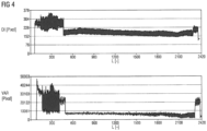
- FIGs 1 to 4 are shown as outputs of measured reflection values known from the state of the art.
- the reflection values represent the process lighting.
- the measured values of the Figures 1 to 4 come from a melt pool monitoring system called "QM-Meltpool 2D" from “Concept Laser” from General Electric (GE). They show examples of manufacturing process values of components which were subsequently subjected to at least one material test, in particular statistical destructive tests, and were found to be "good” or faultless or “bad” or faulty. The evaluation of the components based on the Figures 1 to 4 as such is not possible at first.
- An error indication depends on the choice of opacity curves. These are defined by the respective operator and are therefore not a reliable indicator of an error in the component.
- the quality assessment using image stack-processed melt pool maps (state of the art) is by no means standardized.
- An additional problem here is the poor resolution in the Z direction:
- the indication of defects depends on the opacity limits set by the operator. Defects must be detected over several slices, e.g. if an abnormality is detected in one slice (according to the user's own opacity setting), the layer below and above must be compared to see whether a corresponding error indication is also present in the same place. An error can only be suspected if error indications extend over several slices. However, this could also be due to the selected opacity limits (not an error, just an incorrect setting).
- the invention is based on a Fig. 5 to Fig. 9
- the method illustrated here enables an analytical quality assessment of the process flow based on the measured values recorded for at least one measurement variable representing the process lighting.
- Fig. 5 to Fig. 9 The diode signal was used as an example.
- the data should, if necessary, be separated by exposure step, i.e. evaluated separately in the categories area and contour exposure (F) and (pure) contour exposure (C) in order to minimize the range of variation. This results in normally distributed populations for the respective exposure step groups according to Fig.6 .
- the laser is usually operated with less power in a first layer during production in order to only melt the edge of the layer.
- a subsequent, second layer it is operated with more power in order to melt the first and second layers over the entire surface. It therefore seems sensible to separate and process the data according to the exposure step, i.e. into pure contour exposure and contour and surface exposure. This is done independently of the recording method (diode or camera). The moving average of the coefficients of variation can thus be formed separately according to the exposure step.
- Fig.6 now shows a dot diagram in which the tuples of mean and standard deviation (here, for example, on the diode signals) are shown across all layers. It can be seen that the tuples of good components follow a normal distribution, while the tuples of bad components are clearly (abnormally) scattered. The different regions can be traced back to the exposure steps (pure contour exposure or contour and area exposure in the respective exposure step).
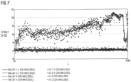
- Fig.7 shows an example of the plot of the inverse coefficients of variation (mean/standard deviation) for diode and/or camera over a window of given layers (point clouds of the Fig.7 ), as well as the moving average (MA COV) as solid lines in the point clouds.
- the diagram shows the mean values of the diode intensities across the layers, which results from the pure, unprocessed transfer of the CSV data.
- the diagram from unprocessed data from several components shows that the quality assessment based on a simple comparison of the recorded signals does not provide clear information about the process quality and that a quality indication is not possible given the existing noise.
- the A dark curve enclosing a light area represents a faulty process.
- Fig.9 shows, as already indicated above, a statistical evaluation of the material characteristics recorded by means of destructive testing of components. This can be used to demonstrate the connection between the process signal and the resulting component properties.
- the outliers are those that show strongly varying (possibly inverse) coefficients of variation in the signal analysis.
- two samples are outliers - their mechanical properties are correlated with the signal curve.
- One advantage of the invention is a numerically based, quantifiable evaluation of the process.
- the algorithm is simple and efficient. Its functionality has been empirically proven using series of tests. Complex processing algorithms and image analyses can thus be avoided.
- the algorithm allows a direct quality forecast. Due to its simplicity, it could also be suitable for online process monitoring, a so-called closed-loop control. Furthermore, process characteristics can be assessed quickly and efficiently and thus adequate quality control can be carried out. Errors in the optical system of a PBF system can be identified immediately and without focus measurement or laser power measurement, etc.
- a device for analyzing a generative manufacturing process, in particular a powder bed process, and for analyzing a workpiece produced layer by layer using the generative manufacturing process, in particular layer by layer, in particular using a powder bed process, comprises at least one sensor for detecting measured values for at least one process emission during the manufacture of the workpiece, in particular for detecting measured values for at least one measured variable representing the process light, and at least one computing unit which is suitably designed for forming mean values and standard deviations from the measured values for predetermined volume elements of the workpiece, in particular also for forming coefficients of variation for the respective volume elements and for forming a moving average of the coefficients of variation over a window of predetermined volume elements, and for checking a distribution of the calculated standard deviations of several predetermined volume elements as a measure of the process quality, in particular for checking the position of the moving average within a predetermined interval.
- Mean values and standard deviations for the measured values of specified volume elements are calculated and it is checked whether the calculated standard deviations are normally distributed for several specified volume elements, in particular for the entire part of the component to be checked.
- the distribution of the standard deviations is a measure of the process quality.
- volume elements Due to the three-dimensionality of the layers produced, they are referred to as volume elements.
- One- or two-dimensional point or line elements cannot be recorded. Areas of the individual layers correspond to sections through the workpiece (cutting planes). The thicknesses of the layers are often essentially constant. Layers of different sizes are created by areas of different sizes, less by different layer thicknesses. The measured values for the volume elements depict the two-dimensional area, but represent a volume element with a given layer thickness.
- the process emissions recorded by the sensors usually occur in a limited band, for example in the near infrared range in the case of SRM.
- the sensors are therefore suitable for recording measured values from a given spectrum.
Landscapes
- Engineering & Computer Science (AREA)
- Chemical & Material Sciences (AREA)
- Manufacturing & Machinery (AREA)
- Materials Engineering (AREA)
- Physics & Mathematics (AREA)
- Automation & Control Theory (AREA)
- General Physics & Mathematics (AREA)
- Analytical Chemistry (AREA)
- Optics & Photonics (AREA)
- Quality & Reliability (AREA)
- General Engineering & Computer Science (AREA)
- Mechanical Engineering (AREA)
- Immunology (AREA)
- Pathology (AREA)
- Biochemistry (AREA)
- Health & Medical Sciences (AREA)
- Life Sciences & Earth Sciences (AREA)
- General Health & Medical Sciences (AREA)
- Human Computer Interaction (AREA)
- Length Measuring Devices By Optical Means (AREA)
- Powder Metallurgy (AREA)
- Investigating Materials By The Use Of Optical Means Adapted For Particular Applications (AREA)
Claims (10)
- Procédé d'analyse d'un procédé de fabrication génératif, dans lequel on détecte des valeurs de mesure se rapportant à au moins une émission de processus lors de la fabrication d'une pièce, dans lequel on calcule des valeurs moyennes et des écart-types des valeurs moyennes d'éléments de volume donnés à l'avance de la pièce, dans lequel on détecte, comme valeurs de mesure se rapportant à la au moins une émission de processus lors de la fabrication de la pièce, des valeurs de mesure se rapportant à au moins une grandeur de mesure représentant une luminescence de processus et dans lequel on contrôle une répartition des écart-types calculés de plusieurs éléments de volume donnés à l'avance comme mesure de la qualité du processus,
caractérisé en ce qu'
à partir des valeurs moyennes et des écart-types calculés, on forme des coefficients de variation, on forme une valeur moyenne mobile des coefficients de variation par une fenêtre d'éléments de volume donnés à l'avance et on contrôle, si la valeur moyenne mobile se trouve dans un intervalle donné à l'avance, si l'intervalle donné à l'avance est dépassé, on en déduit qu'il y a un défaut, et on prescrit l'intervalle en fonction des valeurs moyennes mobiles sur la fenêtre donnée à l'avance. - Procédé suivant la revendication 1, caractérisé en ce que, en présence d'une répartition normale des écart-types calculés de plusieurs éléments de volume donnés à l'avance, on conclue à un processus sans défaut.
- Procédé suivant l'une des revendications 1 ou 2, caractérisé en ce que l'on contrôle des répartitions en deux dimensions des écart-types calculés et des valeurs moyennes calculées, sur le point savoir si ceux-ci sont répartis normalement pour décider de la qualité du processus.
- Procédé suivant la revendication 1, caractérisé en ce que l'on contrôle la variance des valeurs moyennes mobiles sur la fenêtre donnée à l'avance comme mesure de la qualité du processus.
- Procédé suivant la revendication 1, caractérisé en ce que l'on contrôle la courbe des valeurs moyennes mobiles sur la fenêtre donnée à l'avance comme mesure de la qualité du processus.
- Procédé suivant l'une des revendications 1 à 5, caractérisé en ce que l'on détecte des valeurs de mesure se rapportant à des réflexions du bain de fusion.
- Procédé suivant l'une des revendications 1 à 6, caractérisé en ce que l'on détecte et on évalue des valeurs de mesure se rapportant à plusieurs grandeurs de mesure.
- Dispositif d'analyse d'un procédé de fabrication génératif et d'analyse d'une pièce fabriquée par un procédé de fabrication génératif, comprenant au moins un enregistreur de valeurs de mesure pour la détection de valeurs de mesure se rapportant à au moins une émission de processus lors de la fabrication de la pièce et comprenant au moins une unité informatique, qui est constituée de manière appropriée à la formation de valeurs moyennes et d'écart-types, à partir des valeurs de mesure se rapportant à des éléments de volume donnés à l'avance de la pièce,dans lequel le au moins un enregistreur de valeurs de mesure est constitué de manière appropriée à la détection de valeurs de mesure se rapportant à au moins une grandeur de mesure représentant la luminescence du processus,caractérisé en ce que la au moins une unité informatique est constituée de manière appropriée à la formation de coefficients de variation des éléments de volume respectifs pour la formation de valeurs moyennes mobiles des coefficients de variation sur une fenêtre d'éléments de volume donnés à l'avance, pour le contrôle de la position de la valeur moyenne mobile dans un intervalle donné à l'avance, pour décider d'un défaut, si l'intervalle donné à l'avance est dépassé, et pour la prescription de l'intervalle en fonction des valeurs moyennes mobiles sur la fenêtre donnée à l'avance.
- Procédé suivant la revendication 8, caractérisé en ce que l'unité informatique est constituée de manière appropriée pour le contrôle d'une répartition des écart-types calculés de plusieurs éléments de volume donnés à l'avance comme mesure de la qualité du processus.
- Procédé suivant l'une des revendications 8 ou 9, caractérisé en ce qu'il comporte au moins une photodiode et/ou au moins un appareil photographique à grande vitesse de détection de valeurs de mesure se rapportant à au moins une émission de processus lors de la fabrication de la pièce.
Applications Claiming Priority (2)
| Application Number | Priority Date | Filing Date | Title |
|---|---|---|---|
| DE102017219860 | 2017-11-08 | ||
| PCT/EP2018/077541 WO2019091684A1 (fr) | 2017-11-08 | 2018-10-10 | Analyse de procédés sur lit de poudre |
Publications (3)
| Publication Number | Publication Date |
|---|---|
| EP3679436A1 EP3679436A1 (fr) | 2020-07-15 |
| EP3679436C0 EP3679436C0 (fr) | 2024-08-07 |
| EP3679436B1 true EP3679436B1 (fr) | 2024-08-07 |
Family
ID=64023979
Family Applications (1)
| Application Number | Title | Priority Date | Filing Date |
|---|---|---|---|
| EP18793572.1A Active EP3679436B1 (fr) | 2017-11-08 | 2018-10-10 | Analyse de procédés sur lit de poudre |
Country Status (4)
| Country | Link |
|---|---|
| US (1) | US20210191372A1 (fr) |
| EP (1) | EP3679436B1 (fr) |
| ES (1) | ES2991039T3 (fr) |
| WO (1) | WO2019091684A1 (fr) |
Families Citing this family (4)
| Publication number | Priority date | Publication date | Assignee | Title |
|---|---|---|---|---|
| US11867638B2 (en) * | 2020-10-28 | 2024-01-09 | Lawrence Livermore National Security, Llc | System and method for in situ inspection of defects in additively manufactured parts using high speed melt pool pyrometry |
| US20230294201A1 (en) * | 2020-11-04 | 2023-09-21 | Proterial, Ltd. | Method for predicting defect of additive-manufactured product and method for manufacturing additive-manufactured product |
| JP7819018B2 (ja) * | 2021-05-21 | 2026-02-24 | 三菱重工業株式会社 | 検査システム及びその方法並びにプログラム |
| WO2025017205A1 (fr) * | 2023-07-19 | 2025-01-23 | Interspectral Ab | Contrôle qualité de fabrication additive |
Family Cites Families (20)
| Publication number | Priority date | Publication date | Assignee | Title |
|---|---|---|---|---|
| US7624174B2 (en) * | 2003-05-22 | 2009-11-24 | Microsoft Corporation | Self-learning method and system for detecting abnormalities |
| DE102007056984A1 (de) * | 2007-11-27 | 2009-05-28 | Eos Gmbh Electro Optical Systems | Verfahren zum Herstellen eines dreidimensionalen Objekts mittels Lasersintern |
| DE102010003814B4 (de) * | 2009-10-05 | 2017-03-23 | Alfons Tschritter Gmbh | Verfahren zur automatischen Dosierung und Dosiervorrichtung |
| WO2012000648A1 (fr) * | 2010-06-28 | 2012-01-05 | Precitec Kg | Procédé de commande en boucle fermée d'une opération de traitement laser et tête de traitement de matériau au laser utilisant ce procédé |
| US10124410B2 (en) * | 2010-09-25 | 2018-11-13 | Ipg Photonics Corporation | Methods and systems for coherent imaging and feedback control for modification of materials |
| US8868362B2 (en) * | 2012-01-06 | 2014-10-21 | General Electric Company | Electric power metering accuracy |
| JP6318674B2 (ja) * | 2014-02-13 | 2018-05-09 | 富士ゼロックス株式会社 | 障害予測システム、障害予測装置およびプログラム |
| EP2918395B1 (fr) * | 2014-03-12 | 2018-07-04 | Rolls-Royce Corporation | Fabrication additive comprenant une image couche par couche |
| US20150283613A1 (en) * | 2014-04-02 | 2015-10-08 | Arcam Ab | Method for fusing a workpiece |
| DE102014216567A1 (de) * | 2014-08-21 | 2016-02-25 | MTU Aero Engines AG | Verfahren zur Gütebestimmung eines additiv gefertigten Bauteils |
| GB2535710A (en) * | 2015-02-24 | 2016-08-31 | Siemens Ag | Computer device and method for detecting correlations within data |
| US10030825B2 (en) * | 2015-08-03 | 2018-07-24 | Philips Lighting Holding B.V. | Lighting assembly with an optical element for reducing color over angle variation |
| ES2983485T3 (es) * | 2015-11-16 | 2024-10-23 | Renishaw Plc | Método y aparato de fabricación aditiva |
| JP6789646B2 (ja) * | 2016-03-11 | 2020-11-25 | キヤノン株式会社 | 情報処理装置、制御方法、及びプログラム |
| WO2017186851A1 (fr) * | 2016-04-28 | 2017-11-02 | Trinamix Gmbh | Détecteur pour détecter optiquement au moins un objet |
| JP6617855B2 (ja) * | 2017-06-30 | 2019-12-11 | Jfeスチール株式会社 | 転炉の操業監視方法および転炉の操業方法 |
| US11097350B2 (en) * | 2017-07-24 | 2021-08-24 | Raytheon Technologies Corporation | Pre-fusion laser sintering for metal powder stabilization during additive manufacturing |
| JP6735925B2 (ja) * | 2017-08-08 | 2020-08-05 | 三菱重工業株式会社 | 内部欠陥検出システム、三次元積層造形装置、内部欠陥検出方法、三次元積層造形物の製造方法、及び、三次元積層造形物 |
| US20190099945A1 (en) * | 2017-09-29 | 2019-04-04 | Disney Enterprises, Inc. | Composite materials for three dimensional (3d) printing objects for construction applications |
| US11327870B2 (en) * | 2019-01-08 | 2022-05-10 | General Electric Company | System and methods for generating fault indications for an additive manufacturing process based on a probabilistic comparison of the outputs of multiple process models to measured sensor data |
-
2018
- 2018-10-10 EP EP18793572.1A patent/EP3679436B1/fr active Active
- 2018-10-10 ES ES18793572T patent/ES2991039T3/es active Active
- 2018-10-10 US US16/762,585 patent/US20210191372A1/en not_active Abandoned
- 2018-10-10 WO PCT/EP2018/077541 patent/WO2019091684A1/fr not_active Ceased
Also Published As
| Publication number | Publication date |
|---|---|
| EP3679436C0 (fr) | 2024-08-07 |
| ES2991039T3 (es) | 2024-12-02 |
| US20210191372A1 (en) | 2021-06-24 |
| EP3679436A1 (fr) | 2020-07-15 |
| WO2019091684A1 (fr) | 2019-05-16 |
Similar Documents
| Publication | Publication Date | Title |
|---|---|---|
| EP3679436B1 (fr) | Analyse de procédés sur lit de poudre | |
| DE102018129441B4 (de) | System zur Überwachung eines Laserbearbeitungsprozesses, Laserbearbeitungssystem sowie Verfahren zur Überwachung eines Laserbearbeitungsprozesses | |
| DE102015017470B4 (de) | Fehlererkennung für additive fertigungssysteme | |
| EP2993541B1 (fr) | Procédé pour évaluer la qualité d'un composant fabriqué à l'aide d'un procédé de fabrication additif | |
| DE102018102828B4 (de) | Verfahren zur Überwachung eines Schutzglases | |
| EP3044571B1 (fr) | Procédé et dispositif de vérification d'un système d'inspection servant à détecter des défauts de surfaces | |
| DE102015204800B3 (de) | Verfahren und Vorrichtung zur Qualitätsbeurteilung eines mittels eines additiven Herstellungsverfahrens hergestellten Bauteils | |
| DE102013003760A1 (de) | Verfahren und Vorrichtung zur Qualitätsbeurteilung eines mittels eines generativen Lasersinter- und/oder Laserschmelzverfahrens hergestellten Bauteils | |
| EP4150295B1 (fr) | Procédé mis en oeuvre par ordinateur permettant la surveillance de l'état d'un dispositif d'examen d'objets et produit programme informatique correspondant | |
| EP3310510B1 (fr) | Dispositif de fabrication additive avec instrument de mesure | |
| EP2498157B1 (fr) | Dispositif de commande et procédé de commande pour une machine de fabrication d'articles de l'industrie de traitement du tabac en forme de tige | |
| DE102020104462A1 (de) | Verfahren zum Analysieren einer Schweißverbindung beim Laserschweißen von Werkstücken | |
| DE102013215362A1 (de) | Verfahren und Vorrichtung zum Bestimmen einer Einschweißtiefe beim Laserschweißen | |
| EP3488305B1 (fr) | Procédé et dispositif de détermination de la qualité d'un composant | |
| EP3956736B1 (fr) | Procédé mis en oeuvre par ordinateur pour la détermination de défauts d'un objet fabriqué au moyen d'un processus de fabrication additive | |
| DE102017210692A1 (de) | Lebensdauerbestimmungsvorrichtung; Lebensdauerbestimmungsverfahren, und Programm für Schneidwerkzeug | |
| WO2020099323A1 (fr) | Procédé pour détecter une zone de travail d'un dispositif de fabrication additive, et dispositif de fabrication pour une fabrication additive d'éléments à partir d'une matière pulvérulente | |
| DE10103255B4 (de) | Verfahren zur automatischen Beurteilung von Laserbearbeitungsprozessen | |
| DE102016122830A1 (de) | Verfahren und Anordnung zur Abstandsmessung | |
| WO2023017178A1 (fr) | Procédé et système d'analyse d'un processus d'usinage laser sur la base d'un spectrogramme | |
| DE102018214307B4 (de) | System und Verfahren zur Qualitätsprüfung bei der Herstellung von Einzelteilen | |
| DE102011079484A1 (de) | Verfahren und System zur Emissivitätsbestimmung | |
| DE102021107544B4 (de) | Verfahren zur Normierung von Sensorsignalen für die Überwachung eines Laserbearbeitungsprozesses, Verfahren zum Überwachen eines Laserbeitungsprozesses und Laserbearbeitungssystem | |
| EP3789743B1 (fr) | Système et procédé de génération d'un signal de prédiction ainsi que caméra thermique | |
| DE102005032686A1 (de) | Verfahren und Anordnung zum Untersuchen eines Messobjekts mittels invasiver Strahlung |
Legal Events
| Date | Code | Title | Description |
|---|---|---|---|
| STAA | Information on the status of an ep patent application or granted ep patent |
Free format text: STATUS: UNKNOWN |
|
| STAA | Information on the status of an ep patent application or granted ep patent |
Free format text: STATUS: THE INTERNATIONAL PUBLICATION HAS BEEN MADE |
|
| PUAI | Public reference made under article 153(3) epc to a published international application that has entered the european phase |
Free format text: ORIGINAL CODE: 0009012 |
|
| STAA | Information on the status of an ep patent application or granted ep patent |
Free format text: STATUS: REQUEST FOR EXAMINATION WAS MADE |
|
| 17P | Request for examination filed |
Effective date: 20200407 |
|
| AK | Designated contracting states |
Kind code of ref document: A1 Designated state(s): AL AT BE BG CH CY CZ DE DK EE ES FI FR GB GR HR HU IE IS IT LI LT LU LV MC MK MT NL NO PL PT RO RS SE SI SK SM TR |
|
| AX | Request for extension of the european patent |
Extension state: BA ME |
|
| DAV | Request for validation of the european patent (deleted) | ||
| DAX | Request for extension of the european patent (deleted) | ||
| STAA | Information on the status of an ep patent application or granted ep patent |
Free format text: STATUS: EXAMINATION IS IN PROGRESS |
|
| 17Q | First examination report despatched |
Effective date: 20211206 |
|
| GRAP | Despatch of communication of intention to grant a patent |
Free format text: ORIGINAL CODE: EPIDOSNIGR1 |
|
| STAA | Information on the status of an ep patent application or granted ep patent |
Free format text: STATUS: GRANT OF PATENT IS INTENDED |
|
| INTG | Intention to grant announced |
Effective date: 20240325 |
|
| GRAS | Grant fee paid |
Free format text: ORIGINAL CODE: EPIDOSNIGR3 |
|
| GRAA | (expected) grant |
Free format text: ORIGINAL CODE: 0009210 |
|
| STAA | Information on the status of an ep patent application or granted ep patent |
Free format text: STATUS: THE PATENT HAS BEEN GRANTED |
|
| AK | Designated contracting states |
Kind code of ref document: B1 Designated state(s): AL AT BE BG CH CY CZ DE DK EE ES FI FR GB GR HR HU IE IS IT LI LT LU LV MC MK MT NL NO PL PT RO RS SE SI SK SM TR |
|
| REG | Reference to a national code |
Ref country code: GB Ref legal event code: FG4D Free format text: NOT ENGLISH |
|
| REG | Reference to a national code |
Ref country code: CH Ref legal event code: EP |
|
| REG | Reference to a national code |
Ref country code: IE Ref legal event code: FG4D Free format text: LANGUAGE OF EP DOCUMENT: GERMAN |
|
| REG | Reference to a national code |
Ref country code: DE Ref legal event code: R096 Ref document number: 502018014992 Country of ref document: DE |
|
| U01 | Request for unitary effect filed |
Effective date: 20240807 |
|
| U07 | Unitary effect registered |
Designated state(s): AT BE BG DE DK EE FI FR IT LT LU LV MT NL PT RO SE SI Effective date: 20240902 |
|
| U20 | Renewal fee for the european patent with unitary effect paid |
Year of fee payment: 7 Effective date: 20241018 |
|
| REG | Reference to a national code |
Ref country code: ES Ref legal event code: FG2A Ref document number: 2991039 Country of ref document: ES Kind code of ref document: T3 Effective date: 20241202 |
|
| PG25 | Lapsed in a contracting state [announced via postgrant information from national office to epo] |
Ref country code: NO Free format text: LAPSE BECAUSE OF FAILURE TO SUBMIT A TRANSLATION OF THE DESCRIPTION OR TO PAY THE FEE WITHIN THE PRESCRIBED TIME-LIMIT Effective date: 20241107 |
|
| PG25 | Lapsed in a contracting state [announced via postgrant information from national office to epo] |
Ref country code: PL Free format text: LAPSE BECAUSE OF FAILURE TO SUBMIT A TRANSLATION OF THE DESCRIPTION OR TO PAY THE FEE WITHIN THE PRESCRIBED TIME-LIMIT Effective date: 20240807 Ref country code: GR Free format text: LAPSE BECAUSE OF FAILURE TO SUBMIT A TRANSLATION OF THE DESCRIPTION OR TO PAY THE FEE WITHIN THE PRESCRIBED TIME-LIMIT Effective date: 20241108 |
|
| PG25 | Lapsed in a contracting state [announced via postgrant information from national office to epo] |
Ref country code: IS Free format text: LAPSE BECAUSE OF FAILURE TO SUBMIT A TRANSLATION OF THE DESCRIPTION OR TO PAY THE FEE WITHIN THE PRESCRIBED TIME-LIMIT Effective date: 20241207 |
|
| PG25 | Lapsed in a contracting state [announced via postgrant information from national office to epo] |
Ref country code: HR Free format text: LAPSE BECAUSE OF FAILURE TO SUBMIT A TRANSLATION OF THE DESCRIPTION OR TO PAY THE FEE WITHIN THE PRESCRIBED TIME-LIMIT Effective date: 20240807 |
|
| PG25 | Lapsed in a contracting state [announced via postgrant information from national office to epo] |
Ref country code: RS Free format text: LAPSE BECAUSE OF FAILURE TO SUBMIT A TRANSLATION OF THE DESCRIPTION OR TO PAY THE FEE WITHIN THE PRESCRIBED TIME-LIMIT Effective date: 20241107 |
|
| PG25 | Lapsed in a contracting state [announced via postgrant information from national office to epo] |
Ref country code: RS Free format text: LAPSE BECAUSE OF FAILURE TO SUBMIT A TRANSLATION OF THE DESCRIPTION OR TO PAY THE FEE WITHIN THE PRESCRIBED TIME-LIMIT Effective date: 20241107 Ref country code: PL Free format text: LAPSE BECAUSE OF FAILURE TO SUBMIT A TRANSLATION OF THE DESCRIPTION OR TO PAY THE FEE WITHIN THE PRESCRIBED TIME-LIMIT Effective date: 20240807 Ref country code: NO Free format text: LAPSE BECAUSE OF FAILURE TO SUBMIT A TRANSLATION OF THE DESCRIPTION OR TO PAY THE FEE WITHIN THE PRESCRIBED TIME-LIMIT Effective date: 20241107 Ref country code: IS Free format text: LAPSE BECAUSE OF FAILURE TO SUBMIT A TRANSLATION OF THE DESCRIPTION OR TO PAY THE FEE WITHIN THE PRESCRIBED TIME-LIMIT Effective date: 20241207 Ref country code: HR Free format text: LAPSE BECAUSE OF FAILURE TO SUBMIT A TRANSLATION OF THE DESCRIPTION OR TO PAY THE FEE WITHIN THE PRESCRIBED TIME-LIMIT Effective date: 20240807 Ref country code: GR Free format text: LAPSE BECAUSE OF FAILURE TO SUBMIT A TRANSLATION OF THE DESCRIPTION OR TO PAY THE FEE WITHIN THE PRESCRIBED TIME-LIMIT Effective date: 20241108 |
|
| PG25 | Lapsed in a contracting state [announced via postgrant information from national office to epo] |
Ref country code: SM Free format text: LAPSE BECAUSE OF FAILURE TO SUBMIT A TRANSLATION OF THE DESCRIPTION OR TO PAY THE FEE WITHIN THE PRESCRIBED TIME-LIMIT Effective date: 20240807 |
|
| PG25 | Lapsed in a contracting state [announced via postgrant information from national office to epo] |
Ref country code: CZ Free format text: LAPSE BECAUSE OF FAILURE TO SUBMIT A TRANSLATION OF THE DESCRIPTION OR TO PAY THE FEE WITHIN THE PRESCRIBED TIME-LIMIT Effective date: 20240807 |
|
| PG25 | Lapsed in a contracting state [announced via postgrant information from national office to epo] |
Ref country code: SK Free format text: LAPSE BECAUSE OF FAILURE TO SUBMIT A TRANSLATION OF THE DESCRIPTION OR TO PAY THE FEE WITHIN THE PRESCRIBED TIME-LIMIT Effective date: 20240807 |
|
| PLBE | No opposition filed within time limit |
Free format text: ORIGINAL CODE: 0009261 |
|
| STAA | Information on the status of an ep patent application or granted ep patent |
Free format text: STATUS: NO OPPOSITION FILED WITHIN TIME LIMIT |
|
| PG25 | Lapsed in a contracting state [announced via postgrant information from national office to epo] |
Ref country code: MC Free format text: LAPSE BECAUSE OF FAILURE TO SUBMIT A TRANSLATION OF THE DESCRIPTION OR TO PAY THE FEE WITHIN THE PRESCRIBED TIME-LIMIT Effective date: 20240807 |
|
| 26N | No opposition filed |
Effective date: 20250508 |
|
| PG25 | Lapsed in a contracting state [announced via postgrant information from national office to epo] |
Ref country code: IE Free format text: LAPSE BECAUSE OF NON-PAYMENT OF DUE FEES Effective date: 20241010 |
|
| U20 | Renewal fee for the european patent with unitary effect paid |
Year of fee payment: 8 Effective date: 20251020 |
|
| U1H | Name or address of the proprietor changed after the registration of the unitary effect |
Owner name: SIEMENS MOBILITY GMBH; DE |
|
| PGFP | Annual fee paid to national office [announced via postgrant information from national office to epo] |
Ref country code: GB Payment date: 20251111 Year of fee payment: 8 |
|
| REG | Reference to a national code |
Ref country code: CH Ref legal event code: U11 Free format text: ST27 STATUS EVENT CODE: U-0-0-U10-U11 (AS PROVIDED BY THE NATIONAL OFFICE) Effective date: 20260114 |
|
| PG25 | Lapsed in a contracting state [announced via postgrant information from national office to epo] |
Ref country code: CY Free format text: LAPSE BECAUSE OF FAILURE TO SUBMIT A TRANSLATION OF THE DESCRIPTION OR TO PAY THE FEE WITHIN THE PRESCRIBED TIME-LIMIT; INVALID AB INITIO Effective date: 20181010 |
|
| PG25 | Lapsed in a contracting state [announced via postgrant information from national office to epo] |
Ref country code: HU Free format text: LAPSE BECAUSE OF FAILURE TO SUBMIT A TRANSLATION OF THE DESCRIPTION OR TO PAY THE FEE WITHIN THE PRESCRIBED TIME-LIMIT; INVALID AB INITIO Effective date: 20181010 |
|
| PGFP | Annual fee paid to national office [announced via postgrant information from national office to epo] |
Ref country code: ES Payment date: 20260119 Year of fee payment: 8 |
|
| PGFP | Annual fee paid to national office [announced via postgrant information from national office to epo] |
Ref country code: CH Payment date: 20260114 Year of fee payment: 8 |