EP3679689B1 - Verfahren zur konfiguration und / oder wartung eines heimautomatisierungssystems für ein gebäude und zugehöriges heimautomatisierungssystem - Google Patents
Verfahren zur konfiguration und / oder wartung eines heimautomatisierungssystems für ein gebäude und zugehöriges heimautomatisierungssystem Download PDFInfo
- Publication number
- EP3679689B1 EP3679689B1 EP18759346.2A EP18759346A EP3679689B1 EP 3679689 B1 EP3679689 B1 EP 3679689B1 EP 18759346 A EP18759346 A EP 18759346A EP 3679689 B1 EP3679689 B1 EP 3679689B1
- Authority
- EP
- European Patent Office
- Prior art keywords
- home automation
- network
- resources
- automation system
- communicating
- Prior art date
- Legal status (The legal status is an assumption and is not a legal conclusion. Google has not performed a legal analysis and makes no representation as to the accuracy of the status listed.)
- Active
Links
Images


Classifications
-
- H—ELECTRICITY
- H04—ELECTRIC COMMUNICATION TECHNIQUE
- H04L—TRANSMISSION OF DIGITAL INFORMATION, e.g. TELEGRAPHIC COMMUNICATION
- H04L12/00—Data switching networks
- H04L12/28—Data switching networks characterised by path configuration, e.g. LAN [Local Area Networks] or WAN [Wide Area Networks]
- H04L12/2803—Home automation networks
- H04L12/2807—Exchanging configuration information on appliance services in a home automation network
- H04L12/2809—Exchanging configuration information on appliance services in a home automation network indicating that an appliance service is present in a home automation network
-
- E—FIXED CONSTRUCTIONS
- E06—DOORS, WINDOWS, SHUTTERS, OR ROLLER BLINDS IN GENERAL; LADDERS
- E06B—FIXED OR MOVABLE CLOSURES FOR OPENINGS IN BUILDINGS, VEHICLES, FENCES OR LIKE ENCLOSURES IN GENERAL, e.g. DOORS, WINDOWS, BLINDS, GATES
- E06B9/00—Screening or protective devices for wall or similar openings, with or without operating or securing mechanisms; Closures of similar construction
-
- G—PHYSICS
- G05—CONTROLLING; REGULATING
- G05B—CONTROL OR REGULATING SYSTEMS IN GENERAL; FUNCTIONAL ELEMENTS OF SUCH SYSTEMS; MONITORING OR TESTING ARRANGEMENTS FOR SUCH SYSTEMS OR ELEMENTS
- G05B15/00—Systems controlled by a computer
- G05B15/02—Systems controlled by a computer electric
-
- H—ELECTRICITY
- H04—ELECTRIC COMMUNICATION TECHNIQUE
- H04L—TRANSMISSION OF DIGITAL INFORMATION, e.g. TELEGRAPHIC COMMUNICATION
- H04L12/00—Data switching networks
- H04L12/28—Data switching networks characterised by path configuration, e.g. LAN [Local Area Networks] or WAN [Wide Area Networks]
- H04L12/2803—Home automation networks
- H04L12/2816—Controlling appliance services of a home automation network by calling their functionalities
- H04L12/282—Controlling appliance services of a home automation network by calling their functionalities based on user interaction within the home
-
- H—ELECTRICITY
- H04—ELECTRIC COMMUNICATION TECHNIQUE
- H04L—TRANSMISSION OF DIGITAL INFORMATION, e.g. TELEGRAPHIC COMMUNICATION
- H04L12/00—Data switching networks
- H04L12/28—Data switching networks characterised by path configuration, e.g. LAN [Local Area Networks] or WAN [Wide Area Networks]
- H04L12/2803—Home automation networks
- H04L12/2816—Controlling appliance services of a home automation network by calling their functionalities
- H04L12/2821—Avoiding conflicts related to the use of home appliances
-
- H—ELECTRICITY
- H04—ELECTRIC COMMUNICATION TECHNIQUE
- H04L—TRANSMISSION OF DIGITAL INFORMATION, e.g. TELEGRAPHIC COMMUNICATION
- H04L12/00—Data switching networks
- H04L12/28—Data switching networks characterised by path configuration, e.g. LAN [Local Area Networks] or WAN [Wide Area Networks]
- H04L12/2803—Home automation networks
- H04L12/283—Processing of data at an internetworking point of a home automation network
- H04L12/2832—Interconnection of the control functionalities between home networks
-
- H—ELECTRICITY
- H04—ELECTRIC COMMUNICATION TECHNIQUE
- H04L—TRANSMISSION OF DIGITAL INFORMATION, e.g. TELEGRAPHIC COMMUNICATION
- H04L67/00—Network arrangements or protocols for supporting network services or applications
- H04L67/01—Protocols
- H04L67/12—Protocols specially adapted for proprietary or special-purpose networking environments, e.g. medical networks, sensor networks, networks in vehicles or remote metering networks
-
- H—ELECTRICITY
- H04—ELECTRIC COMMUNICATION TECHNIQUE
- H04L—TRANSMISSION OF DIGITAL INFORMATION, e.g. TELEGRAPHIC COMMUNICATION
- H04L67/00—Network arrangements or protocols for supporting network services or applications
- H04L67/50—Network services
- H04L67/51—Discovery or management thereof, e.g. service location protocol [SLP] or web services
-
- G—PHYSICS
- G05—CONTROLLING; REGULATING
- G05B—CONTROL OR REGULATING SYSTEMS IN GENERAL; FUNCTIONAL ELEMENTS OF SUCH SYSTEMS; MONITORING OR TESTING ARRANGEMENTS FOR SUCH SYSTEMS OR ELEMENTS
- G05B2219/00—Program-control systems
- G05B2219/10—Plc systems
- G05B2219/16—Plc to applications
- G05B2219/163—Domotique, domestic, home control, automation, smart, intelligent house
-
- G—PHYSICS
- G05—CONTROLLING; REGULATING
- G05B—CONTROL OR REGULATING SYSTEMS IN GENERAL; FUNCTIONAL ELEMENTS OF SUCH SYSTEMS; MONITORING OR TESTING ARRANGEMENTS FOR SUCH SYSTEMS OR ELEMENTS
- G05B2219/00—Program-control systems
- G05B2219/20—Pc systems
- G05B2219/25—Pc structure of the system
- G05B2219/25011—Domotique, I-O bus, home automation, building automation
-
- G—PHYSICS
- G05—CONTROLLING; REGULATING
- G05B—CONTROL OR REGULATING SYSTEMS IN GENERAL; FUNCTIONAL ELEMENTS OF SUCH SYSTEMS; MONITORING OR TESTING ARRANGEMENTS FOR SUCH SYSTEMS OR ELEMENTS
- G05B2219/00—Program-control systems
- G05B2219/20—Pc systems
- G05B2219/25—Pc structure of the system
- G05B2219/25168—Domotique, access through internet protocols
-
- G—PHYSICS
- G05—CONTROLLING; REGULATING
- G05B—CONTROL OR REGULATING SYSTEMS IN GENERAL; FUNCTIONAL ELEMENTS OF SUCH SYSTEMS; MONITORING OR TESTING ARRANGEMENTS FOR SUCH SYSTEMS OR ELEMENTS
- G05B2219/00—Program-control systems
- G05B2219/20—Pc systems
- G05B2219/26—Pc applications
- G05B2219/2642—Domotique, domestic, home control, automation, smart house
Definitions
- the present invention relates to a method of configuring and / or maintaining a home automation system for a building as well as an associated home automation system.
- the invention relates to the field of building automation, both for commercial buildings and residential buildings, whether individual or collective.
- Automations are the sets of rules that govern the control of electrical equipment by a programmable supervision system, in order to ensure better comfort for the occupants of the building or to optimize energy consumption. These automations are controlled by a programmable supervision system, in order to ensure better comfort for the occupants of the building or to optimize energy consumption.
- These applications are designated under the term “Technical Building Management” or, more generally, under the expression “Building Automation Systems” in English.
- home automation In the residential sector, automations are more often referred to by the term “home automation”. To simplify, hereinafter, the term home automation will be used to designate both residential and tertiary applications.
- the equipment of the same building is connected to a control unit, which has the function of supervising this equipment and controlling its operation.
- This connection is often made by connecting the equipment by dedicated wire links.
- each device is connected directly to the control unit by means of one or more cables, in a master / slave configuration.
- this connection is made by connecting the equipment to a common data bus, such as a multipoint bus allowing a bidirectional connection, for example of the RS485 type.
- This data bus is connected to the central unit, so as to form a network which allows the exchange of data between the equipment and the control unit.
- this situation also offers limited flexibility, since any modification after installation requires rewiring the network, either to add new equipment or to modify its distribution in the building.
- this known situation has limits in terms of the number of devices that can be accommodated in the network.
- solutions of the RS485 type commonly used have limited addressing capacities, and in practice only allow a maximum of 255 individual devices to be connected on the same bus. This limit is prohibitive when it comes to equipping large buildings and / or comprising a large number of equipment to be managed.
- contemporary applications make it necessary to be able to manage an increasingly large number of equipment, for example in the context of the Internet of Things or the so-called intelligent management of buildings.
- communicating elements home automation equipment or network equipment
- communicating elements are used at very high frequencies. weak.
- an actuator is used on average four times per day, for a total use of about five minutes per day. It therefore remains inactive for almost 99.7% of the time.
- Each communicating element includes one or more microprocessors, which are also underused.
- a home automation system comprising several communicating devices, a large part of the computing power of the home automation system is in fact unused.
- the home automation system is managed by a central control unit capable of performing a predefined number of functions.
- a problem arises when one wishes to develop the home automation system. If the capacity limit of the control unit is reached, no additional functions can be added without changing the central control unit. Likewise, in such a home automation system, it is impossible to add a functionality not supported by the central control unit without changing the latter.
- the invention more particularly intends to remedy by proposing a simple solution for configuring, or even reconfiguring, a home automation system for buildings, as well as for ensuring the maintenance of this home automation system.
- the invention relates to a method according to claim 1.
- this method of configuring a home automation system for a building is implemented by a configuration device, the home automation system comprising a plurality of communicating elements. in order to perform a plurality of home automation functions and a communication network to which the communicating elements are connected, each communicating element comprising a network interface having a network address.
- the communication network makes it possible to manage a large number of home automation equipment within the building, while exhibiting increased flexibility in installation and development.
- the invention relates to a system according to claim 6.
- this home automation system for a building is configured by the configuration method according to one of claims 1 to 5.
- the invention relates to a method according to claim 12.
- it is a method of maintaining a home automation system according to one of claims 6 to 11.
- the invention will be described with reference to a particular embodiment in which the network architecture of the home automation system for a building corresponds to the architecture of the building.
- This example is in no way limiting and the invention can be applied to other network architectures.
- the figure 1 represents a building 2, comprising several zones Z1, Z2, Z3, Z4.
- Building 2 is equipped with a home automation system 4 which comprises a set of home automation equipment distributed in the areas of building 2, as well as a control system for these home automation equipment.
- the home automation system 4 is here intended to provide comfort and / or energy management functions for the building 2, such as heating, ventilation and air conditioning, as well as lighting management and opening control functions. , such as blinds or roller shutters placed in front of windows of building 2 and / or security functions such as room surveillance and alarm.
- the home automation equipment set includes home automation equipment such as controllable home automation devices 6, control points 8 and sensors 10.
- the control system comprises in particular a programmable control unit 12 and a communication network 14, internal to the building 2, the communication network 14 being arranged to allow communication of the home automation equipment of the home automation system 4 with the control unit 12.
- the home automation equipment of the home automation system 4 which is connected to this communication network 14 is, in what follows, said to belong to the communication network 14.
- the home automation equipment and the control system are here connected to one or more power sources, not shown, of building 2.
- the zones of building 2 correspond to portions of building 2 which are located inside and / or outside this building and which are each intended to receive part of the home automation equipment of the home automation system 4.
- Building 2 can be an office complex, or a residential building, or a commercial or industrial building, or any combination of these uses. It may in particular be a building or a detached house.
- home automation is not limited to purely domestic and residential use.
- areas of building 2 correspond to levels of building 2, such as floors or basements.
- These zones can also be rooms or groups of rooms of building 2, possibly separated from each other by partitions, these rooms being able to be distributed within one or more levels of building 2.
- These zones can also correspond to rooms. facades or parts of a facade, such as a part of a facade corresponding to the same floor.
- These zones can be delimited independently of the physical structure of the building 2.
- the same room of the building 2 can include several zones. Such zones can also be located outside the building 2, for example when they correspond to a facade or a portion of the facade of the building 2.
- zones are for example defined during the design of the building 2 and / or during the design and / or the installation of the home automation system 4.
- the areas of the building 2 are distinct from each other.
- areas of the building 2 can overlap and / or be nested with one another.
- zones here denoted Z1, Z2, Z3 and Z4, are defined with reference to building 2.
- this number may be different. It is in particular adapted according to the configuration of building 2 and the functions of the home automation system 4.
- zones Z1, Z2, Z3 and Z4 are schematically illustrated inside the same floor of building 2.
- each controllable home automation device 6 comprises an actuator that can be controlled by means of at least one control signal.
- controllable home automation devices 6 are here illustrated identically. However, they may differ from each other and perform different functions within the home automation system 4.
- the actuator of the apparatus 6 contains an electric motor coupled with a mechanical load and arranged to move and / or regulate an element of the building 2.
- the mechanical load of the device 6 is a blackout shutter, such as a panel, a blind or an opaque curtain, associated with at least one opening of the building 2, such as a window or a bay window.
- a blackout shutter such as a panel, a blind or an opaque curtain
- the movement of this blackout shutter makes it possible to regulate the amount of sunlight received by the building 2 through this opening.
- the mechanical load of the device 6 is a compressor suitable for implementing an expansion-compression cycle of a heat transfer fluid within a refrigeration system of building 2, such as an air conditioner or a heat pump, in order to regulate the temperature inside the building 2.
- the mechanical load of the device 6 is a pump or a fan intended to set in motion a volume of fluid within the building 2, for example to suck or blow air within a ventilation system, or to circulate water or a heat transfer fluid in a dedicated pipe.
- the actuator of the apparatus 6 can control an electrical switching device, in order to control the switching on and off of a light source, such as a battery of neon lamps or light-emitting diodes, at the same time. within the building 2.
- a light source such as a battery of neon lamps or light-emitting diodes
- the controllable home automation device 6 can also be lighting, for example, interior or exterior lighting or a lighting control system, an alarm system, or even a video camera, in particular a video surveillance camera.
- a control point 8 is intended to receive control instructions from a user of the building 2, in order to control, directly or indirectly, one or more of the controllable home automation devices 6 and / or to control the control unit. command 12.
- each control point 8 comprises here a man-machine interface, not shown, comprising data entry means, such as one or more switches and / or one or more pushbuttons and / or one or more. rotary knobs and / or a touch screen.
- the control point 8 can also include a connection interface for connecting to it external control means, for example one or more individual switches arranged around the control point 8 and being connected by a wired link to the latter.
- the man-machine interface of the control point 8 may also include display means, such as indicator lights and / or an electronic screen, for example with liquid crystal, to display, intended for the user, information. relating to the operation of the home automation system 4 or to instructions entered on said man-machine interface.
- display means such as indicator lights and / or an electronic screen, for example with liquid crystal, to display, intended for the user, information. relating to the operation of the home automation system 4 or to instructions entered on said man-machine interface.
- the control points 8 can take the form of a portable remote control associated with a fixed receiver or, as a variant, of a fixed control terminal secured to a wall of the building 2.
- control points 8 are illustrated identically here, but they may differ from one another and perform different functions within the home automation system 4.
- Each sensor 10 is intended to convert one or more physical quantities relating to the state of the building 2 or of its environment or of a home automation equipment into one or more signals proportional to this physical quantity.
- This signal is, for example, an electrical signal, a light signal or a radiofrequency signal.
- This signal can be transmitted by the sensor to at least one home automation device and / or the control system, for example, to the control unit 12.
- One or more sensors 10 can be integrated into a controllable home automation device 6, to a control point 8 or even to the control unit 12.
- the home automation installation 4 can also include one or more independent sensors to these elements.
- the physical quantities measured by the sensors 10 are, without limitation, a temperature, for example a temperature of a wall or of the ambient air, a humidity level, a luminosity value, or a value.
- a temperature for example a temperature of a wall or of the ambient air
- a humidity level for example of a wall or of the ambient air
- a luminosity value for example of a light-emitting diode
- a value for example of water, gas or electricity
- the opening state of a roller shutter the position of an opening such as a window, motorized or not or the presence or absence of a user.
- sensors 10 are shown here identically but may have differences between them within the home automation system 4.
- each home automation device comprises a network interface 40, which allows it to communicate on the network 14 and which will be defined later in the description.
- zone Z1 comprises three controllable home automation devices 6, a control point 8 and a sensor 10.
- Zone Z2 has three controllable home automation devices 6.
- Zone Z3 comprises a home automation device 6, a control point 8 and a sensor 10.
- Zone Z4 includes a home automation device 6 and a sensor 10.
- controllable home automation devices 6 of zone Z2 are suitable for moving blackout shutters fitted to openings of building 2 made in this zone Z2.
- controllable home automation devices 6 of the zone Z1 here form part of an air conditioning and refrigeration system for the air circulating in the zone Z1. Their operation is regulated as a function of control commands received by the control point 8 and as a function of a temperature measured by the sensor 10 located in this zone Z1.
- Each home automation device of the home automation system including in particular the devices 6, the control points 8 and the sensors 10, is connected to the control unit 12 via the communications network 14 and for this purpose comprises a network interface 40 to connect to this communications network 14.
- each home automation device 6 receives control signals via the communications network 14.
- Each control point 8 transmits the control instructions received via the communications network 14.
- Each sensor 10 sends the measured information. through the communications network 14.
- the communication takes place by an exchange of messages, for example in the form of packets, these messages each containing a header, which includes a destination of the message, and payload data, such as a command command or a value of. physical quantity measured by a sensor.
- messages for example in the form of packets, these messages each containing a header, which includes a destination of the message, and payload data, such as a command command or a value of. physical quantity measured by a sensor.
- the communication protocol used is an IP (“Internet Protocol”) protocol, for example the IPv6 protocol.
- IPv6 Internet Protocol
- IPv4 IPv4 protocol
- the figure 2 shows in more detail the example of the communication network 14 of the figure 1 .
- the home automation equipment 6, 8, 10 associated with zones Z3 and Z4 of building 2 are not illustrated therein.
- the communication network 14 is a hierarchical network with several hierarchy levels, also called ranks. It comprises a main network B, which comprises in particular a common data bus, forming a backbone physical link 20, also called “backbone” in English, to which the control unit 12 is connected.
- main network B which comprises in particular a common data bus, forming a backbone physical link 20, also called “backbone” in English, to which the control unit 12 is connected.
- the communication network 14 also includes at least one sub-network, denoted generically by the reference SN.
- This sub-network comprises network equipment 22, 24, which is directly connected to the backbone link 20 via a network interface 40 and which forms the head of this sub-network SN.
- It may be an interconnection network equipment item, also called a gateway 22, intended to interconnect two parts of distinct networks, for example, of different technologies.
- It can also be a router 24 when the main network B and the subnetwork SN are of the same nature. Gateways and routers behave similarly except that the router does not convert data transmission formats.
- These two network devices are intermediate elements of the communication network 14 ensuring the routing of the packets. Their role is to send packets from one network interface 40 to another according to a set of rules forming a routing table.
- two gateways 22 are connected to the backbone link 20, thus forming two distinct subnetworks SN1 and SN2. Only one of these two subnetworks, bearing the reference SN1, is described in what follows.
- the number of SN subnets may be different.
- the SN subnets are directly connected to the main network via gateways, and have an associated first rank in the hierarchical network.
- Each sub-network SN contains at least one home automation device 6, 8, 10 of the home automation system 4, connected to the corresponding gateway 22 via a physical link 26, preferably wired.
- the communication network 14 further comprises sub-sub-networks of a rank lower than that of the sub-networks SN, and are denoted generically by the reference SSN.
- Each SSN sub-sub-network comprises network equipment, advantageously a router 24, connecting it to an SN sub-network or to a sub-sub-network hierarchical level higher than his own.
- the network equipment 22, 24 forms the head of this SSN sub-sub-network.
- each sub-sub-sub-network SSN1 and SSN2 has an associated rank "n-1"
- the sub-sub-sub-network SSN3 has a rank "n-2" .
- Each router 24 at the head of the rank “n-1” sub-subnetwork is connected to a gateway 22 via a physical link 26, preferably wired.
- each network equipment 22, 24 head of a sub-subnetwork of rank "nk”, with k greater than or equal to 2 is connected to a router 24 of higher rank "n -k + 1 ”, via a physical link 26, preferably wired.
- the hierarchical network can include up to twelve hierarchy levels, including that of the main network B.
- Each SSN sub-sub-network comprises one or more home automation devices 6, 8, 10, connected to the corresponding router 24 via a physical link 26, each home automation device being connected to the physical link 26 using their respective network interfaces 40.
- the home automation devices connected, via the same physical link 26, to the same router 24 are here said to be part of the same local subnet.
- the SN subnetworks and each SSN subnetwork of lower rank than that of the SN subnetwork are each associated with a zone of the building 2.
- An SN sub-network and / or an SSN sub-sub-network is said to be “associated” with a zone Z1, Z2, Z3, Z4 of building 2 when the home automation devices 6, 8, 10 belonging to this sub-network are themselves themselves associated with this zone, for example because they are physically located inside this zone Z1, Z2, Z3, Z4 of building 2.
- the number and structure of SN sub-networks and SSN sub-sub-networks, as well as their association with the zones of building 2, are preferably chosen according to the configuration of building 2 and the functionalities fulfilled by home automation system 4 .
- the physical links 26 are multipoint serial data buses of the RS485 or EIA-485 type.
- the physical link 26 which connects each network device 22, 24 to one another and which connects them to the home automation devices 6, 8, 10 is an RS485 type multipoint serial data bus.
- a physical link 26 of the RS485 type has advantages in this communication network 14, because it makes it possible to use very long data buses, for example up to 1 km long, without degrading the network too much. quality of the signal circulating there. Limiting the number of home automation equipment 6, 8, 10 and / or network equipment 22, 24 connected on the same physical link 26 is not penalizing, thanks to the hierarchical architecture which makes it possible to connect a large number of subnets.
- control unit 12 is adapted to be connected to an external data network 30, such as the Internet network, independently of the communication network 14.
- an external data network such as the Internet network
- control unit 12 can communicate with a remote computer server connected to this external network 30, for example to send reports on the operating state of the home automation system 4 for diagnostic purposes, or to receive flight instructions.
- the control unit 12 can also communicate via the external network 30 with one or more remote users, for example provided with a communication terminal such as a computer 32, an intelligent mobile telephone device or “ smartphones ” in English, a tablet. touchscreen or any other equivalent equipment.
- the communication network 14 is adapted to operate according to a predefined communication protocol, such as the IP protocol, in order to ensure communication between the communicating elements of the home automation system 4 which are connected to this communication network 14.
- a predefined communication protocol such as the IP protocol
- the communication protocol used is the IPv6 protocol.
- This communication protocol is implemented here using the network interfaces 40 which equip the various home automation equipment 6, 8, 10 and network equipment 22, 24 of the home automation system 4 which are connected by the communication network 14, in particular by virtue of their network interface 40.
- communicating element will denote the network equipment 22, 24 and the communicating elements 6, 8, 10.
- the routers 24 and the gateway (s) 22 include specific network interfaces.
- these network interfaces each implement a protocol stack, that is to say a stack of protocol layers, each protocol layer relying on those below in order to provide additional functionality.
- the figure 3 schematically represents the network interface of a communicating element.
- the function of the network interface of a communicating element is to connect this communicating element to one or more communication networks. It thus allows it to communicate with the other communicating elements of the network (s) to which it is connected.
- each network interface 40 comprises a network controller 42, a memory 44 and an input-output module 46, also called “transceiver” in English, the input-output module 46 being here provided with a connector arranged for physically connecting the input-output module 46 to a physical layer of the communication network 14.
- the physical layer of the communication network 14 is partly formed by the physical links 26.
- the network controller 42 comprises an electronic computer, for example one or more processors, microprocessors or any other equivalent means, programmed to process the data passing through the communication network 14 and through the connector of the input-output module 46.
- the network controller 42 is programmed to automatically process the data received by the input-output module 46 and being intended for the network interface 40.
- the processing can for example consist in extracting and decoding the content of packets received by the network interface and / or transmit this content to the home automation equipment with which it is associated.
- the network controller 42 is programmed to automatically prepare the data sent by the home automation equipment to which it is associated, with a view to their sending to one or more home automation equipment connected to the communication network 14.
- the network controller 42 is suitable for implementing program code instructions making it possible to execute steps of the network address configuration method according to the invention.
- the RS485 type data buses used here to form, in particular, the physical link 26, each comprise a pair of conductive wires, preferably twisted.
- a carrier signal is emitted, for example in the form of an electrical voltage between this pair of conductive wires, this voltage being able to take predefined values so as to encode information, for example in a binary way.
- the shape of the carrier signal is for example defined by the TIA / EIA-485-A standard.
- link 26 is a bidirectional link of the “half-duplex” type.
- the memory 44 here contains a network address, not shown, which uniquely identifies the interface 40 on the network 14 and which therefore identifies the corresponding home automation equipment on the network 4.
- the network interface 40 is here compatible with the standard. IPv6.
- the network address is an IP address, preferably of the IPv6 type.
- the memory 44 advantageously contains executable instructions to ensure the previously described operation of the controller 42.
- the figure 4 schematically represents a generic network device 60 intended to be used in the network 14.
- the device 60 corresponds for example to the router 24.
- This equipment 60 comprises an electronic computer 62, a computer memory 64, a first network interface 66 and a second network interface 68.
- the interface 66 is for example intended to be connected to a first sub-network, while the interface 68 is intended to be connected to a second sub-network, of a lower rank than the first sub-network.
- the network interfaces 66 and 68 are, for example, each physically similar to the interface 40.
- the device 60 has a network address 50 which identifies it at least within the first subnet.
- the electronic computer 62 is in particular programmed to ensure routing of the data packets arriving from the part of the network associated with one or the other of the interfaces 66 or 68 to a part of the network accessible through the other interface 66 or 68, depending on the destination of these data packets.
- the equipment 60 here comprises a routing table, for example recorded in the memory 64.
- interfaces 66 and 68 are here compatible with RS485 type data buses. Everything that is described with reference to interfaces 40 therefore applies to interfaces 66 and 68.
- Gateway 22 operates similarly to apparatus 60 described above, except that here network interface 66 is connected with backbone 20.
- the communication protocol used by the network 14 makes it possible to ensure the addressing of the messages exchanged between the elements of the system 44 by a packet switching mechanism.
- the first device when an element of the system 4, such as a control point, needs to send data to another element of the system 4, such as a device 6, then the first device generates a message containing the data to send and containing the address of the destination element.
- the message is thus routed within the network 14 until it reaches its destination. More precisely, the message intended for a local device belonging to the same group passes through the intermediary of the bus 26.
- the message intended for a device located outside the group is routed by means of the router 24 associated with this group, which it does. redirects to the corresponding sub-network, possibly via the equipment 22 and the backbone link 20.
- the network protocol used within the communication network 14 and, in particular, implemented by the network interfaces 40 here comprises several interlinked protocol layers. These protocol layers are each implemented by the protocol stack of each network interface 40 by software and / or electronic means, in particular thanks to the network controller 42.
- the home automation system 4 also includes a software application layer, programmed to form a home automation system 4 according to a REST compatible architecture, for “REpresentational State Transfer” also called “RESTful” architecture.
- This application programming software interface comprises a set of functions and / or predefined methods, preferably implemented identically on all the communicating elements of the communication network 14.
- the resources of each home automation device 6, 8, 10 and of each network device 22, 24 are represented in a uniform, standardized way, and are accessible by the application programming software interface without having to worry about the underlying structure of the communicating element 6, 8, 10, 22, 24 .
- Each communicating element 6, 8, 10, 22, 24 comprises an electronic computer, not illustrated, which is programmed to implement this application programming software interface, using executable software instructions.
- this electronic computer comprises one or more programmable logic computing units, such as a microprocessor or a microcontroller.
- This electronic computer also includes a data storage medium as well as a computer working memory.
- executable software instructions for implementing the programming software interface application are stored in the data storage medium.
- This data storage medium and this working computer memory can, as a variant, both be implemented on the same non-volatile information recording medium, such as a Flash memory module.
- the electronic computer of the network interface 40 makes it possible to exchange data within the communication network 14, for example with other nodes of the communication network provided with a similar application.
- the electronic computer is programmed to interact with the protocol stack implemented by the network interface 40, and preferably, to interact more particularly with the protocol layer of the network interface 40 previously described.
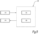
- each communicating element 6, 8, 10, 22, 24 is represented in the form of one or more software objects 70, an example of which is illustrated generically on the diagram. figure 5 , within this application layer.
- each software object 70 is a software representation of at least part of a communicating element, implemented by the electronic computer described above and incorporated in this communicating element 6, 8, 10, 22, 24.
- a same communicating element can thus comprise several software objects 70, preferably organized according to a hierarchical tree structure with a so-called “father” object comprising one or more “child” software objects.
- each communicating element implements one or more software objects 70 which represent this communicating element abstractly in the form of resources.
- the home automation system includes three types of resource: inputs 72, outputs 74 and logical units 76.
- each software object 70 has one or more inputs 72, one or more outputs 74 and / or one or more logical units 76
- Each of these resources has a defined state 78 which may vary over time.
- the state of a wind sensor can correspond to the measured wind speed.
- State 78 is implemented here by a data structure, such as a numeric variable, a Boolean variable or a character string, which is stored in the data storage medium or in the working memory.
- a data structure such as a numeric variable, a Boolean variable or a character string, which is stored in the data storage medium or in the working memory.
- all of the software objects 70 are structured in a similar fashion.
- the inputs 72 correspond to the communicating elements making it possible to supply data at the input of the home automation system 4. They may be, for example, sensors. or control point.
- the data can correspond to a signal representative of a physical quantity, for example a physical quantity associated with a home automation function in the building 2, such as a temperature, a wind speed or a light intensity.
- the input data can come from the building or its surroundings.
- the entries 72 can also correspond to one or more databases or one or more memories, the entry data associated with these types of entries corresponding to the values stored in these databases or memories.
- the databases and memories include a network address so that they can be addressable.
- the outputs 74 correspond for example to the motors and / or to the actuators.
- the logical units 76 interpret and process the data supplied by the inputs 72.
- the logical units 76 can be configured to implement logical operations and / or more or less complex calculation operations depending on the type of input data and / or depending on the type of application. These may be, for example, comparison operations.
- the logic unit can, for example, compare one or more input data with each other or compare one or more input data with respect to one or more predetermined threshold values.
- the logic unit can be configured to implement functions of the hysteresis type, for example to determine an activation delay according to an operating history, in particular in the case of the management of a temperature by a control system. heating / air conditioning or for closing / opening a shutter depending on the sunshine or the time of day.
- Logical drives can be configured to perform combine operations.
- the result of the processing for example a motor command
- the output (s) concerned On reception, the result of the processing will trigger the output concerned.
- Logical units are neutral. They process input data regardless of their nature. The same logic unit can process data from a temperature sensor as well as from a wind sensor or from a control point. Logical units also have no knowledge of the nature of the outputs. Logical units are simply configured to change one or more input data to one or more values to be passed to one or more outputs for control.
- the logical units are distributed over the entire communication network 14. Their location depends neither on the inputs for which they process data nor on the outputs which they control. They can be used alone or in combination with other logical units in order to perform more complex calculations.
- a home automation system is thus obtained having an “intelligence” which can be distributed over the entire communication network 14.
- this “intelligence”, represented by the logical units, is flexible. It can be enlarged by adding other logical units 76 in the communication network 14.
- the logical units can correspond to dedicated equipment, that is to say so-called logical equipment providing only calculation functions.
- the home automation system 4 can include so-called logical equipment, not shown, which is dedicated to logical functions accessible to the communicating elements of the communication network 14. It can be, for example, a server. electronic calculation, a computer, a signal processing module of the DSP type for “ Digital Signal Processor ” in the English language, a data storage server (“network access sucrage ” in the English language).
- the so-called logical equipment comprises at least one network interface to which a network address has been allocated so as to be able to be addressable.
- Logic units can be integrated into communicating elements, for example a motor or a control point.
- the control point is thus seen by the home automation system 4 as one or more inputs 72 and one or more logic units 76.
- logic units and inputs, or outputs can have the same network address.
- a logic unit can also be integrated in a network equipment 22, 24 or a sensor 10.
- Logic units can be advanced logic devices configured to implement specific home automation functions in conjunction with inputs and outputs.
- Specific home automation functions can, for example, be functions for managing solar gains on a building (or “ shadow management ” in English) functions for monitoring the sun (or “ sun tracking ” in English).
- the logical units can use data coming from inputs of different kinds like sensors of different types (brightness, wind temperature, time) and data coming from databases like solar diagrams, typical meteorological years (or TMY for “ Typical Meteorological Year ” in English).
- the logical units can implement specific operations such as operations of combining data of different natures, according to one of several predefined combination formulas. he can They are combinations of solar orientation data with solar luminance data in a sun tracking application.
- the logical units can implement operations for managing access to one or more databases, for example, as part of a solar gain management application in order to retrieve prerecorded data relating to the spatial configuration of the building. 2 and data relating to shading masks due to the urban environment or data relating to a solar diagram with a view to forecasting the sunshine received on a facade of the building as a function of the time of day.
- each resource 72, 74, 76 is a variable, here stored in the memory of the electronic computer.
- This variable can be of integer type, or a string of characters and / or symbols, or a Boolean value, or an indexable set of elements (or “array” in English) or any other predefined data type. However, whatever the chosen data type, this data type is the same for all the software objects 70.
- These resource states 72, 74, 76 can be modified by means of specific accessors, or call functions. defined by the application programming software interface.
- the application programming software interface is suitable for listing the resources 72, 74, 76 available on the software object 70 as well as for listing the child software objects attached to this software object 70. This information is for example listed. within dedicated variables accessible by the interface, such as indexable strings of characters (or "string arrays" in English).
- the state 78 associated with each resource 72, 74, 76 can vary over time. It is defined here deterministically, as a function of the data entering the inputs 72, by means of predefined rules. These rules are for example recorded within the electronic computer itself associated with this home automation equipment 6, 8, 10.
- Each resource 72, 74, 76 has an initial state 78.
- a resource receives, on the corresponding input (s) 72, input data for a predefined period of time.
- a new state 78 is calculated, which is a function of the initial state and of the input data received during this period of time. This calculation is carried out according to predefined rules.
- the state of an input can correspond to the measurement of a parameter or or to a real state of a home automation device 6, 8, 10.
- the state of an output 74 can correspond to a setpoint relative to a parameter, a position or a temperature for example.
- each home automation device 6, 8, 10 is deterministic and depends on the interactions between this home automation device and its exterior, these interactions being able to be measured and controlled.
- the state of each home automation equipment 6, 8, 10 is accessible by the other home automation equipment 6, 8, 10 connected to the communication network 14 via the application programming software interface, the status of the equipment home automation that can correspond to the state of a resource associated with this home automation equipment.
- This type of resource-oriented architecture contrasts with the known home automation systems comprising a control unit in which the state of an item of equipment at a given time has no way of being known by other home automation equipment, except by going through it. the control unit.
- Each item of equipment 6, 8, 10 is programmed, thanks to the aforementioned electronic computer, to automatically respond to requests from other nodes of the network in the manner for example of an HTTP server, for “Hyper Text Transfer Protocol” in English. .
- each message contains an identifier of the targeted home automation equipment 6, 8, 10 as well as one or more commands, which may be accompanied by parameters or variables associated with these commands.
- the application programming software interface uses protocols that include HTTP requests.
- the commands correspond to known HTTP commands such as GET, POST, PUT, REPLY or even DELETE.
- Each software object 70 is here identified within the application protocol of the home automation system 4 by a unique access path.
- This access path is for example a uniform resource identifier, denoted URI for “Uniform Resource Identifier” in English.
- This access path is for example a string of alphanumeric characters and / or predefined symbols.
- each one can operate in the manner of an HTTP proxy by relaying messages to other home automation equipment of the communication network 14.
- the application programming software interface comprises a function making it possible to consult the state of one or more properties 76 of the software object 70, for example, to obtain a list of the resources of the equipment. Automation.
- this function when called by means of a corresponding query, returns this list of properties. This list is for example transmitted to the sender of the request in the form of one or more messages on the communication network 14.
- the software interface also includes a so-called introspection function which, for each software object 70, implements a discovery function to list, recursively, each of the child software objects associated with this software object 70 so as to establish one or more lists their respective properties.
- the application programming software interface is also implemented on network equipment such as gateways 22 and routers 24, for example by means of their respective computers 62.
- network equipment such as gateways 22 and routers 24, for example by means of their respective computers 62.
- a subnetwork can be represented by such a software object 70, the resources of which then correspond to the combination of the individual resources of each of the home automation equipment 6, 8, 10 belonging to the subnetwork.
- the software objects 70 associated with this home automation equipment are, in this case, seen as child software objects which are attached to the software object 70 associated with the network equipment 22, 24 to which the home automation equipment is connected.
- an input type resource can be associated with a wind sensor, the state of the resource being equivalent to a wind speed value at an instant t.
- a logical unit type resource can be associated with one of the routers of the communication network, which also manages an output type resource.
- the logic unit can be defined by a comparison with a predetermined wind value, and the output by a command order to fall back on equipment of the blind type.
- the control order is for example sent over the network.
- Such a device receiving such a control order will react accordingly.
- This same device can have an input type resource, in which its status will be recorded, during the execution of the order then at the end of the execution. The state of this input type resource can then be used for the purpose of confirming the execution of the command.
- any subsystem SN, SSN, of the communication network 14 can be seen as a system in its own right, modeled independently of the rest of the system. communication network 14 and being described globally in terms of inputs, outputs and resources of home automation equipment 6, 8, 10 which belong to this sub-network.
- a sub-network comprising home automation equipment 6, 8, 10 can be considered as a full-fledged home automation subsystem, which can, if necessary, operate independently of the rest of the system 4, for example in the event of a failure during which said sub-network is isolated from the rest of the communication network 14 and cannot more communicate with it.
- the rest of the home automation system 4 can continue to operate when certain components, such as these home automation equipment 6, 8 and 10, are unavailable or unreachable.
- the network equipment and / or the home automation equipment concerned can find the logical resources necessary for its operation, for example by exploring the software interfaces of the software objects corresponding to the home automation equipment to which it is still connected.
- the intelligence of the home automation system 4 is distributed within the communication network 14.
- the control unit 12 can therefore be omitted and the network operate autonomously.
- One embodiment presents a method of configuring a home automation system 4 for a building 2. This method is implemented by a configuration device in order to configure the home automation system 4.
- the configuration tool may comprise a configuration module programmed to implement the configuration method. It is assumed that the home automation system comprises a plurality of communicating elements 6, 8, 10, 22, 24 configured to perform a plurality of home automation functions and a communication network 14 to which the communicating elements are connected.
- the installer connects the configuration device to any point of the communication network and implements a discovery procedure in order to identify the communicating elements 6, 8, 10, 22, 24 present in the system. Automation.
- a mapping in the communication network of the various resources 72, 74, 76 offered by each communicating element discovered is then carried out.
- the configuration device can interrogate each communicating element discovered in order to count the resources 72, 74, 76 that they offer and to know the functions that they are capable of performing.
- the configuration device may also associate a uniform URI resource identifier unique to each enumerated resource.
- the uniform resource identifier contains the network address of the network interface of the communicating element modeled, at least in part, by this resource.
- the home automation functions of the home automation system 4 are then programmed taking into account the mapping of the resources 72, 74, 76 in the communication network 14.
- the programming step comprises establishing links between inputs 72, logical units 76 and outputs 74 and to configure logic units 76 to process data provided by inputs 72 and transmit the result of processing to outputs 76 for control.
- the programming step can also include transmitting, to at least some resources, the established links and thus allowing the autonomous operation of the network.
- the state of a logical unit type resource can include not only a function, but also the links established during programming, for example, the identification of the input resource to be retrieved and of the input resource. output to update.
- the processing of the data supplied by one or more inputs can be carried out by a single logical unit or can be divided between several distinct logical units distributed in the communication network 14.
- the links between the inputs, the logic units and the outputs can be established automatically by the configuration device.
- the programming device can include one or more libraries of home automation functions, for example stored in a memory area of the device.
- This function library allows the configuration tool to know the types of resources needed to perform each home automation function.
- the links between the inputs, the logical units and the outputs are for example established automatically by the configuration device, according to the libraries of home automation functions.
- the library may indicate that to perform a sun protection function, the system needs one or more inputs configured to provide data that corresponds to brightness information, one or more logical units capable of processing the data provided by the inputs and to transmit the processed data to one or more outputs.
- the logic unit can for example be programmed to compare the data supplied by the input (s) with a predetermined threshold value and, when this threshold value is reached, transmit a command to a motor, for example in order to lower a blind.
- the configuration method can be implemented automatically by the configuration device following its connection to the communication network 14.
- Another embodiment of the invention relates to a method for maintaining a home automation system for a building. It is assumed that the home automation system has been configured beforehand, for example according to the configuration method described above.
- the maintenance process can be implemented by a maintenance tool. According to one embodiment, the maintenance tool and the configuration tool described above can be identical.
- the maintenance tool can be connected to any point of the communication network.
- the maintenance method comprises a step of discovering the communicating elements 6, 8, 10, 22, 24 present in the home automation system, a mapping step in the communication network 14, of resources 72, 74, 76 offered by each communicating element. discovered and a step of recovering the various links between the resources of each communicating element discovered as well as their states.
- the resource mapping step comprises a sub-step of counting the resources 72, 74, 76 proposed by each communicating element discovered and a sub-step of associating a uniform resource identifier with each enumerated resource. .
- the method can comprise a step of reprogramming home automation functions of the home automation system 4. This reprogramming can be carried out taking into account a new mapping of resources 72, 74, 76 in the communication network and / or new home automation functions to be performed. .
- the maintenance method can include a step of correcting defective resources and / or links, for example following one or more breakdowns in the home automation system.
- the maintenance method can for example be implemented following the addition of new communicating elements in the home automation system and / or the realization of new home automation functions compared to an initial configuration.
- the reprogramming step can therefore consist in establishing links between inputs, logic units and outputs and configuring the logic units in order to process data supplied by the inputs and transmit the result of the processing to the outputs in order to control them.
- the maintenance tool can save a previous configuration of the home automation system in a memory area.
- This old configuration can be compared to the current configuration of the home automation system, for example with the aim of detecting possible breakdowns and / or failures in the home automation system. The aim of this comparison may also be to discover new communicating elements installed since the last intervention.
- the installation and maintenance of the home automation system are also facilitated. Indeed, when an installer wishes to check the state of the home automation system 4, for example to add network equipment or home automation equipment or to establish a diagnosis, he does not always know beforehand which network or home automation equipment is already installed or how they interact with the rest of the home automation system 4. Thanks to the invention, it suffices to implement steps for detecting resources within the home automation system 4, either at the scale of the complete home automation system 4, or at the level one or more subnetworks, or even at the level of one or more network or home automation equipment in order to list the available resources as well as their respective states. This is for example achieved by connecting a client terminal such as a computer or a mobile communication device connected to the communication network 14, provided with a screen and adapted to access the software interface and display a list or a map of different resources.
- a client terminal such as a computer or a mobile communication device connected to the communication network 14, provided with a screen and adapted to access the software interface and display a list or a map of different resources.
- the software interface makes it possible to easily list the resources offered by the home automation equipment associated with these zones, as well as the associated inputs-outputs.
Landscapes
- Engineering & Computer Science (AREA)
- Automation & Control Theory (AREA)
- Signal Processing (AREA)
- Computer Networks & Wireless Communication (AREA)
- Computing Systems (AREA)
- Medical Informatics (AREA)
- Physics & Mathematics (AREA)
- Computer Security & Cryptography (AREA)
- General Engineering & Computer Science (AREA)
- Health & Medical Sciences (AREA)
- General Health & Medical Sciences (AREA)
- General Physics & Mathematics (AREA)
- Structural Engineering (AREA)
- Human Computer Interaction (AREA)
- Civil Engineering (AREA)
- Architecture (AREA)
- Selective Calling Equipment (AREA)
- Small-Scale Networks (AREA)
- Computer And Data Communications (AREA)
Claims (14)
- Verfahren zum Konfigurieren eines Gebäudeautomationssystems (4) für ein Gebäude (2), das durch eine Konfigurationsvorrichtung implementiert wird, das Gebäudeautomationssystem umfassend eine Vielzahl von kommunizierenden Elementen (6, 8, 10, 22, 24) zum Ausführen einer Vielzahl von Gebäudeautomationsfunktionen und ein Kommunikationsnetz (14), mit dem die kommunizierenden Elemente verbunden sind, jedes kommunizierende Element umfassend eine Netzschnittstelle, die eine Netzadresse und ein elektronisches Rechengerät aufweist, das ein oder mehrere Software-Objekte (70) implementiert, die dieses kommunizierende Element in Form von Ressourcen von mindestens drei Typen modellieren: Eingang (72), Ausgang (74) und logische Einheit (76),das Gebäudeautomationssystem (4) auch umfassend eine Software-Anwendungsschicht, in der die Ressourcen, die jedes kommunizierende Element (6, 8, 10, 22, 24) zu jedem Zeitpunkt bereitstellen kann, mittels einer Software-Anwendungsprogrammierschnittstelle zugänglich sind, die durch das elektronische Rechengerät von jedem kommunizierenden Element (6, 8, 10, 22, 24) implementiert wird;wobei jedes Software-Objekt (70) eine Software-Darstellung von mindestens einem Teil eines kommunizierenden Elements innerhalb der Software-Anwendungsschicht ist,das Verfahren umfassend die folgenden Schritte:- Entdecken der verschiedenen kommunizierenden Elemente des Kommunikationsnetzes (14),- Abbildung, in dem Kommunikationsnetz (14), der Ressourcen (72, 74, 76), die von jedem entdeckten kommunizierenden Element bereitgestellt werden, wobei der Schritt einer Abbildung der Ressourcen einen Teilschritt eines Zählens der Ressourcen, die von jedem entdeckten kommunizierenden Element bereitgestellt werden, und einen Teilschritt eines Assoziierens einer Ressourcen-Kennung zu jeder gezählten Ressource umfasst;- Programmierung der Gebäudeautomationsfunktionen des Gebäudeautomationssystems (4) unter Berücksichtigung der Abbildung der Ressourcen (72, 74, 76) in dem Kommunikationsnetz (14), der Programmierschritt umfassend die Herstellung von Verbindungen zwischen den Eingängen, den logischen Einheiten und den Ausgängen und die Konfiguration der logischen Einheiten, damit sie die Daten, die von den Eingängen bereitgestellt werden, verarbeiten und das Resultat der Verarbeitung an die Ausgänge zu deren Steuerung übertragen können.
- Verfahren nach Anspruch 1, wobei der Programmierschritt ein Übertragen der hergestellten Verbindungen an mindestens bestimmte Ressourcen (72, 74, 76) umfasst.
- Verfahren nach Anspruch 2, umfassend ein Herstellen der Verbindungen zwischen den Eingängen, den logischen Einheiten und den Ausgängen auf automatische Weise durch die Konfigurationsvorrichtung abhängig von Bibliotheken, die in einem Speicherbereich der Konfigurationsvorrichtung gespeichert sind.
- Verfahren nach einem der Ansprüche 1 bis 3, wobei die Durchführung des Verfahrens auf mehrere verschiedene logische Einheiten aufgeteilt ist, die in dem Kommunikationsnetz verteilt sind.
- Verfahren nach einem der vorherigen Ansprüche, wobei das Verfahren durch die Konfigurationsvorrichtung automatisch nach deren Verbindung an einem beliebigen Punkt des Kommunikationsnetzes (14) ausgeführt wird.
- Gebäudeautomationssystem (4) für ein Gebäude (2), wobei das Gebäudeautomationssystem durch das Konfigurationsverfahren nach einem der vorherigen Ansprüche konfiguriert wird, das Gebäudeautomationssystem umfassend eine Vielzahl von kommunizierenden Elementen (6, 8, 10, 22, 24), zum Ausführen einer Vielzahl von Gebäudeautomationsfunktionen und ein Kommunikationsnetz (14), mit dem die kommunizierenden Elemente verbunden sind, jedes kommunizierende Element umfassend eine Netzschnittstelle, die eine Netzadresse aufweist und ein oder mehrere Software-Objekte (70) implementiert, die dieses kommunizierende Element in Form von Ressourcen (72, 74, 76) von mindestens drei Typen modellieren: Eingang (72), Ausgang (74) und logische Einheit (76);das Gebäudeautomationssystem (4) auch umfassend eine Software-Anwendungsschicht, in der die Ressourcen, die jedes kommunizierende Element (6, 8, 10, 22, 24) zu jedem Zeitpunkt bereitstellen kann, mittels einer Software-Anwendungsprogrammierschnittstelle zugänglich sind, die durch das elektronische Rechengerät von jedem kommunizierenden Element (6, 8, 10, 22, 24) implementiert wird;wobei jedes Software-Objekt (70) eine Software-Darstellung von mindestens einem Teil eines kommunizierenden Elements innerhalb der Software-Anwendungsschicht ist.
- System nach dem vorherigen Anspruch, wobei jede Ressource durch eine eindeutige Ressourcen-Kennung (URI) identifiziert ist, die die Netzadresse der Netzschnittstelle des kommunizierenden Elements enthält, das mindestens teilweise durch diese Ressource modelliert wird.
- System nach Anspruch 6 oder 7, wobei ein Sensor (10) oder ein Steuerpunkt (8) in Form von mindestens einem Eingang (72) modelliert wird.
- System nach einem der Ansprüche 6 bis 8, wobei ein steuerbares Gebäudeautomationsgerät in Form von mindestens einem Ausgang (74) modelliert wird.
- System nach einem der Ansprüche 6 bis 10, wobei ein Netzwerkgerät (22, 24) in Form von mindestens einer logischen Einheit (76) modelliert wird.
- System nach dem vorherigen Anspruch, wobei das Kommunikationsnetz (14) in Form eines hierarchischen Netzes angeordnet ist.
- Wartungsverfahren eines Gebäudeautomationssystems für ein Gebäude nach einem der Ansprüche 6 bis 11, wobei das Gebäudeautomationssystem durch das Konfigurationsverfahren nach einem der Ansprüche 1 bis 5 konfiguriert ist, das Wartungsverfahren umfassend die folgenden Schritte:- Entdecken verschiedener kommunizierender Elemente des Kommunikationsnetzes (14),- Abbildung, in dem Kommunikationsnetz (14), von Ressourcen (72, 74, 76), die von jedem entdeckten kommunizierenden Element bereitgestellt werden, wobei der Schritt einer Abbildung der Ressourcen einen Teilschritt eines Zählens der Ressourcen, die von jedem entdeckten kommunizierenden Element bereitgestellt werden, und einen Teilschritt eines Assoziierens einer Ressourcen-Kennung zu jeder gezählten Ressource umfasst;- Abrufung der verschiedenen Verbindungen zwischen den Ressourcen von jedem erkannten kommunizierenden Element sowie deren Zustände, der Programmierschritt umfassend die Herstellung von Verbindungen zwischen den Eingängen, den logischen Einheiten und den Ausgängen und die Konfiguration der logischen Einheiten, damit sie die Daten, die von den Eingängen bereitgestellt werden, verarbeiten und das Resultat der Verarbeitung an die Ausgänge zu deren Steuerung übertragen können.
- Verfahren nach Anspruch 12, ferner umfassend einen Neuprogrammierungsschritt von Gebäudeautomationsfunktionen des Gebäudeautomationssystems (4) unter Berücksichtigung einer neuen Abbildung der Ressourcen (72, 74, 76) in dem Kommunikationsnetz (14) und/oder neuer auszuführender Gebäudeautomationsfunktionen.
- Verfahren nach einem der Ansprüche 12 bis 13, ferner umfassend einen Korrekturschritt fehlerhafter Ressourcen und/oder Verbindungen.
Applications Claiming Priority (2)
| Application Number | Priority Date | Filing Date | Title |
|---|---|---|---|
| FR1758143A FR3070811B1 (fr) | 2017-09-04 | 2017-09-04 | Procede de configuration et/ou de maintenance d'un systeme domotique pour un batiment et dispositif de configuration d'un systeme domotique associe |
| PCT/EP2018/073607 WO2019043222A1 (fr) | 2017-09-04 | 2018-09-03 | Procédé de configuration et/ou de maintenance d'un système domotique pour un bâtiment et dispositif de configuration d'un système domotique associé |
Publications (2)
| Publication Number | Publication Date |
|---|---|
| EP3679689A1 EP3679689A1 (de) | 2020-07-15 |
| EP3679689B1 true EP3679689B1 (de) | 2021-12-01 |
Family
ID=60515538
Family Applications (1)
| Application Number | Title | Priority Date | Filing Date |
|---|---|---|---|
| EP18759346.2A Active EP3679689B1 (de) | 2017-09-04 | 2018-09-03 | Verfahren zur konfiguration und / oder wartung eines heimautomatisierungssystems für ein gebäude und zugehöriges heimautomatisierungssystem |
Country Status (4)
| Country | Link |
|---|---|
| US (1) | US20210006427A1 (de) |
| EP (1) | EP3679689B1 (de) |
| FR (1) | FR3070811B1 (de) |
| WO (1) | WO2019043222A1 (de) |
Families Citing this family (3)
| Publication number | Priority date | Publication date | Assignee | Title |
|---|---|---|---|---|
| FR3098971B1 (fr) * | 2019-07-15 | 2021-07-09 | Somfy Activites Sa | Procédé et dispositif de commande sans fil pour actionneurs couplés à un réseau filaire. |
| FR3116162A1 (fr) * | 2020-11-06 | 2022-05-13 | Schneider Electric Industries Sas | Procédés et systèmes de configuration automatique d’un micro-réseau électrique |
| FR3116367B1 (fr) * | 2020-11-13 | 2024-01-12 | Innovative Tech | Procédé de cartographie automatique d’équipements d’un système de comptage et de guidage à la place d’usagers dans un parking |
Family Cites Families (6)
| Publication number | Priority date | Publication date | Assignee | Title |
|---|---|---|---|---|
| US7750812B2 (en) * | 2005-03-03 | 2010-07-06 | Sensormatic Electronics, Llc. | Apparatus for and method of using an intelligent network and RFID signal router |
| US10333731B2 (en) * | 2005-06-09 | 2019-06-25 | Whirlpool Corporation | Methods and apparatus for communicatively coupling internal components within appliances, and appliances with external components and accessories |
| US7865252B2 (en) * | 2007-01-26 | 2011-01-04 | Autani Corporation | Upgradeable automation devices, systems, architectures, and methods |
| US20080273486A1 (en) * | 2007-04-13 | 2008-11-06 | Hart Communication Foundation | Wireless Protocol Adapter |
| US8219660B2 (en) * | 2010-02-26 | 2012-07-10 | Trane International Inc. | Simultaneous connectivity and management across multiple building automation system networks |
| US9806810B2 (en) * | 2015-01-28 | 2017-10-31 | Abl Ip Holding Llc | Auto-discovery of neighbor relationships and lighting installation self-mapping via visual light communication |
-
2017
- 2017-09-04 FR FR1758143A patent/FR3070811B1/fr not_active Expired - Fee Related
-
2018
- 2018-09-03 WO PCT/EP2018/073607 patent/WO2019043222A1/fr not_active Ceased
- 2018-09-03 US US16/643,992 patent/US20210006427A1/en not_active Abandoned
- 2018-09-03 EP EP18759346.2A patent/EP3679689B1/de active Active
Also Published As
| Publication number | Publication date |
|---|---|
| WO2019043222A1 (fr) | 2019-03-07 |
| EP3679689A1 (de) | 2020-07-15 |
| FR3070811B1 (fr) | 2021-05-21 |
| US20210006427A1 (en) | 2021-01-07 |
| FR3070811A1 (fr) | 2019-03-08 |
Similar Documents
| Publication | Publication Date | Title |
|---|---|---|
| EP3318035B1 (de) | Verfahren zur steuerung einer heimautomationsanlage | |
| EP3679689B1 (de) | Verfahren zur konfiguration und / oder wartung eines heimautomatisierungssystems für ein gebäude und zugehöriges heimautomatisierungssystem | |
| EP3318019B1 (de) | Heimautomatisierungssystem und verfahren zur erzeugung von topologie eines heimautomatisierungssystems | |
| EP3679712B1 (de) | Verfahren zur automatischen konfiguration der netzwerkadresse eines zu einem heimautomationssystem gehörenden kommunikationselements, zugehörige netzwerkschnittstelle, kommunizierendes element und heimautomationssystem | |
| EP3318018B1 (de) | Verfahren zum registrieren einer zentralen steuereinheit einer heimautomatisierungsanlage und entsprechende computerprogrammprodukte | |
| EP3679688B1 (de) | Heimautomationssystem für gebäude, gebäude mit einem solchen heimautomationssystem, und konfigurationssystem | |
| EP3679695B1 (de) | Verfahern und netzwerkschnittstelle für ein heimautomatisierungsgerät, heimautomatisierungssystem für ein gebäude mit einem solchen heimautomatisierungsgerät und gebäude mit einem solchen heimautomatisierungssystem | |
| EP3318017B1 (de) | Verfahren zur entdeckung der konfiguration einer heimautomatisierungsanlage | |
| EP3679694B1 (de) | Verfahren zur kommunikation, die in einem heimautomatisierungssystem für ein gebäude implementiert ist, und zugehöriges heimautomatisierungssystem | |
| EP3679711B1 (de) | Verfahren zur kommunikation zwischen kommunikationselementen, die zu einem heimautomatisierungssystem gehören | |
| EP4000054B1 (de) | Verfahren und vorrichtung zur drahtlosen steuerung von mit einem drahtgebundenen netzwerk verbundenen aktuatoren | |
| EP3317731A1 (de) | Verfahren zur steuerung und verfahren zum konfigurieren einer heimautomatisierungsanlage | |
| EP3317732B1 (de) | Verfahren zur anmeldung einer zentralen steuereinheit einer heimautomatisierungsanlage |
Legal Events
| Date | Code | Title | Description |
|---|---|---|---|
| STAA | Information on the status of an ep patent application or granted ep patent |
Free format text: STATUS: UNKNOWN |
|
| STAA | Information on the status of an ep patent application or granted ep patent |
Free format text: STATUS: THE INTERNATIONAL PUBLICATION HAS BEEN MADE |
|
| PUAI | Public reference made under article 153(3) epc to a published international application that has entered the european phase |
Free format text: ORIGINAL CODE: 0009012 |
|
| STAA | Information on the status of an ep patent application or granted ep patent |
Free format text: STATUS: REQUEST FOR EXAMINATION WAS MADE |
|
| 17P | Request for examination filed |
Effective date: 20200312 |
|
| AK | Designated contracting states |
Kind code of ref document: A1 Designated state(s): AL AT BE BG CH CY CZ DE DK EE ES FI FR GB GR HR HU IE IS IT LI LT LU LV MC MK MT NL NO PL PT RO RS SE SI SK SM TR |
|
| AX | Request for extension of the european patent |
Extension state: BA ME |
|
| DAV | Request for validation of the european patent (deleted) | ||
| DAX | Request for extension of the european patent (deleted) | ||
| GRAP | Despatch of communication of intention to grant a patent |
Free format text: ORIGINAL CODE: EPIDOSNIGR1 |
|
| STAA | Information on the status of an ep patent application or granted ep patent |
Free format text: STATUS: GRANT OF PATENT IS INTENDED |
|
| INTG | Intention to grant announced |
Effective date: 20210707 |
|
| GRAS | Grant fee paid |
Free format text: ORIGINAL CODE: EPIDOSNIGR3 |
|
| GRAA | (expected) grant |
Free format text: ORIGINAL CODE: 0009210 |
|
| STAA | Information on the status of an ep patent application or granted ep patent |
Free format text: STATUS: THE PATENT HAS BEEN GRANTED |
|
| AK | Designated contracting states |
Kind code of ref document: B1 Designated state(s): AL AT BE BG CH CY CZ DE DK EE ES FI FR GB GR HR HU IE IS IT LI LT LU LV MC MK MT NL NO PL PT RO RS SE SI SK SM TR |
|
| REG | Reference to a national code |
Ref country code: GB Ref legal event code: FG4D Free format text: NOT ENGLISH |
|
| REG | Reference to a national code |
Ref country code: AT Ref legal event code: REF Ref document number: 1452838 Country of ref document: AT Kind code of ref document: T Effective date: 20211215 Ref country code: CH Ref legal event code: EP |
|
| REG | Reference to a national code |
Ref country code: IE Ref legal event code: FG4D Free format text: LANGUAGE OF EP DOCUMENT: FRENCH |
|
| REG | Reference to a national code |
Ref country code: DE Ref legal event code: R096 Ref document number: 602018027536 Country of ref document: DE |
|
| REG | Reference to a national code |
Ref country code: NL Ref legal event code: FP |
|
| REG | Reference to a national code |
Ref country code: LT Ref legal event code: MG9D |
|
| REG | Reference to a national code |
Ref country code: AT Ref legal event code: MK05 Ref document number: 1452838 Country of ref document: AT Kind code of ref document: T Effective date: 20211201 |
|
| PG25 | Lapsed in a contracting state [announced via postgrant information from national office to epo] |
Ref country code: RS Free format text: LAPSE BECAUSE OF FAILURE TO SUBMIT A TRANSLATION OF THE DESCRIPTION OR TO PAY THE FEE WITHIN THE PRESCRIBED TIME-LIMIT Effective date: 20211201 Ref country code: LT Free format text: LAPSE BECAUSE OF FAILURE TO SUBMIT A TRANSLATION OF THE DESCRIPTION OR TO PAY THE FEE WITHIN THE PRESCRIBED TIME-LIMIT Effective date: 20211201 Ref country code: FI Free format text: LAPSE BECAUSE OF FAILURE TO SUBMIT A TRANSLATION OF THE DESCRIPTION OR TO PAY THE FEE WITHIN THE PRESCRIBED TIME-LIMIT Effective date: 20211201 Ref country code: BG Free format text: LAPSE BECAUSE OF FAILURE TO SUBMIT A TRANSLATION OF THE DESCRIPTION OR TO PAY THE FEE WITHIN THE PRESCRIBED TIME-LIMIT Effective date: 20220301 Ref country code: AT Free format text: LAPSE BECAUSE OF FAILURE TO SUBMIT A TRANSLATION OF THE DESCRIPTION OR TO PAY THE FEE WITHIN THE PRESCRIBED TIME-LIMIT Effective date: 20211201 |
|
| PG25 | Lapsed in a contracting state [announced via postgrant information from national office to epo] |
Ref country code: SE Free format text: LAPSE BECAUSE OF FAILURE TO SUBMIT A TRANSLATION OF THE DESCRIPTION OR TO PAY THE FEE WITHIN THE PRESCRIBED TIME-LIMIT Effective date: 20211201 Ref country code: PL Free format text: LAPSE BECAUSE OF FAILURE TO SUBMIT A TRANSLATION OF THE DESCRIPTION OR TO PAY THE FEE WITHIN THE PRESCRIBED TIME-LIMIT Effective date: 20211201 Ref country code: NO Free format text: LAPSE BECAUSE OF FAILURE TO SUBMIT A TRANSLATION OF THE DESCRIPTION OR TO PAY THE FEE WITHIN THE PRESCRIBED TIME-LIMIT Effective date: 20220301 Ref country code: LV Free format text: LAPSE BECAUSE OF FAILURE TO SUBMIT A TRANSLATION OF THE DESCRIPTION OR TO PAY THE FEE WITHIN THE PRESCRIBED TIME-LIMIT Effective date: 20211201 Ref country code: HR Free format text: LAPSE BECAUSE OF FAILURE TO SUBMIT A TRANSLATION OF THE DESCRIPTION OR TO PAY THE FEE WITHIN THE PRESCRIBED TIME-LIMIT Effective date: 20211201 Ref country code: GR Free format text: LAPSE BECAUSE OF FAILURE TO SUBMIT A TRANSLATION OF THE DESCRIPTION OR TO PAY THE FEE WITHIN THE PRESCRIBED TIME-LIMIT Effective date: 20220302 Ref country code: ES Free format text: LAPSE BECAUSE OF FAILURE TO SUBMIT A TRANSLATION OF THE DESCRIPTION OR TO PAY THE FEE WITHIN THE PRESCRIBED TIME-LIMIT Effective date: 20211201 |
|
| PG25 | Lapsed in a contracting state [announced via postgrant information from national office to epo] |
Ref country code: SM Free format text: LAPSE BECAUSE OF FAILURE TO SUBMIT A TRANSLATION OF THE DESCRIPTION OR TO PAY THE FEE WITHIN THE PRESCRIBED TIME-LIMIT Effective date: 20211201 Ref country code: SK Free format text: LAPSE BECAUSE OF FAILURE TO SUBMIT A TRANSLATION OF THE DESCRIPTION OR TO PAY THE FEE WITHIN THE PRESCRIBED TIME-LIMIT Effective date: 20211201 Ref country code: RO Free format text: LAPSE BECAUSE OF FAILURE TO SUBMIT A TRANSLATION OF THE DESCRIPTION OR TO PAY THE FEE WITHIN THE PRESCRIBED TIME-LIMIT Effective date: 20211201 Ref country code: PT Free format text: LAPSE BECAUSE OF FAILURE TO SUBMIT A TRANSLATION OF THE DESCRIPTION OR TO PAY THE FEE WITHIN THE PRESCRIBED TIME-LIMIT Effective date: 20220401 Ref country code: EE Free format text: LAPSE BECAUSE OF FAILURE TO SUBMIT A TRANSLATION OF THE DESCRIPTION OR TO PAY THE FEE WITHIN THE PRESCRIBED TIME-LIMIT Effective date: 20211201 Ref country code: CZ Free format text: LAPSE BECAUSE OF FAILURE TO SUBMIT A TRANSLATION OF THE DESCRIPTION OR TO PAY THE FEE WITHIN THE PRESCRIBED TIME-LIMIT Effective date: 20211201 |
|
| REG | Reference to a national code |
Ref country code: DE Ref legal event code: R097 Ref document number: 602018027536 Country of ref document: DE |
|
| PG25 | Lapsed in a contracting state [announced via postgrant information from national office to epo] |
Ref country code: IS Free format text: LAPSE BECAUSE OF FAILURE TO SUBMIT A TRANSLATION OF THE DESCRIPTION OR TO PAY THE FEE WITHIN THE PRESCRIBED TIME-LIMIT Effective date: 20220401 |
|
| PLBE | No opposition filed within time limit |
Free format text: ORIGINAL CODE: 0009261 |
|
| STAA | Information on the status of an ep patent application or granted ep patent |
Free format text: STATUS: NO OPPOSITION FILED WITHIN TIME LIMIT |
|
| PG25 | Lapsed in a contracting state [announced via postgrant information from national office to epo] |
Ref country code: DK Free format text: LAPSE BECAUSE OF FAILURE TO SUBMIT A TRANSLATION OF THE DESCRIPTION OR TO PAY THE FEE WITHIN THE PRESCRIBED TIME-LIMIT Effective date: 20211201 Ref country code: AL Free format text: LAPSE BECAUSE OF FAILURE TO SUBMIT A TRANSLATION OF THE DESCRIPTION OR TO PAY THE FEE WITHIN THE PRESCRIBED TIME-LIMIT Effective date: 20211201 |
|
| 26N | No opposition filed |
Effective date: 20220902 |
|
| PG25 | Lapsed in a contracting state [announced via postgrant information from national office to epo] |
Ref country code: SI Free format text: LAPSE BECAUSE OF FAILURE TO SUBMIT A TRANSLATION OF THE DESCRIPTION OR TO PAY THE FEE WITHIN THE PRESCRIBED TIME-LIMIT Effective date: 20211201 |
|
| PG25 | Lapsed in a contracting state [announced via postgrant information from national office to epo] |
Ref country code: MC Free format text: LAPSE BECAUSE OF FAILURE TO SUBMIT A TRANSLATION OF THE DESCRIPTION OR TO PAY THE FEE WITHIN THE PRESCRIBED TIME-LIMIT Effective date: 20211201 |
|
| REG | Reference to a national code |
Ref country code: BE Ref legal event code: MM Effective date: 20220930 |
|
| PG25 | Lapsed in a contracting state [announced via postgrant information from national office to epo] |
Ref country code: IT Free format text: LAPSE BECAUSE OF FAILURE TO SUBMIT A TRANSLATION OF THE DESCRIPTION OR TO PAY THE FEE WITHIN THE PRESCRIBED TIME-LIMIT Effective date: 20211201 |
|
| PG25 | Lapsed in a contracting state [announced via postgrant information from national office to epo] |
Ref country code: LU Free format text: LAPSE BECAUSE OF NON-PAYMENT OF DUE FEES Effective date: 20220903 |
|
| PG25 | Lapsed in a contracting state [announced via postgrant information from national office to epo] |
Ref country code: IE Free format text: LAPSE BECAUSE OF NON-PAYMENT OF DUE FEES Effective date: 20220903 |
|
| PG25 | Lapsed in a contracting state [announced via postgrant information from national office to epo] |
Ref country code: BE Free format text: LAPSE BECAUSE OF NON-PAYMENT OF DUE FEES Effective date: 20220930 |
|
| PG25 | Lapsed in a contracting state [announced via postgrant information from national office to epo] |
Ref country code: CY Free format text: LAPSE BECAUSE OF FAILURE TO SUBMIT A TRANSLATION OF THE DESCRIPTION OR TO PAY THE FEE WITHIN THE PRESCRIBED TIME-LIMIT Effective date: 20211201 |
|
| PG25 | Lapsed in a contracting state [announced via postgrant information from national office to epo] |
Ref country code: MK Free format text: LAPSE BECAUSE OF FAILURE TO SUBMIT A TRANSLATION OF THE DESCRIPTION OR TO PAY THE FEE WITHIN THE PRESCRIBED TIME-LIMIT Effective date: 20211201 Ref country code: HU Free format text: LAPSE BECAUSE OF FAILURE TO SUBMIT A TRANSLATION OF THE DESCRIPTION OR TO PAY THE FEE WITHIN THE PRESCRIBED TIME-LIMIT; INVALID AB INITIO Effective date: 20180903 |
|
| PG25 | Lapsed in a contracting state [announced via postgrant information from national office to epo] |
Ref country code: MT Free format text: LAPSE BECAUSE OF FAILURE TO SUBMIT A TRANSLATION OF THE DESCRIPTION OR TO PAY THE FEE WITHIN THE PRESCRIBED TIME-LIMIT Effective date: 20211201 |
|
| REG | Reference to a national code |
Ref country code: CH Ref legal event code: U11 Free format text: ST27 STATUS EVENT CODE: U-0-0-U10-U11 (AS PROVIDED BY THE NATIONAL OFFICE) Effective date: 20251001 |
|
| PGFP | Annual fee paid to national office [announced via postgrant information from national office to epo] |
Ref country code: DE Payment date: 20250916 Year of fee payment: 8 |
|
| PGFP | Annual fee paid to national office [announced via postgrant information from national office to epo] |
Ref country code: NL Payment date: 20250909 Year of fee payment: 8 |
|
| PGFP | Annual fee paid to national office [announced via postgrant information from national office to epo] |
Ref country code: GB Payment date: 20250919 Year of fee payment: 8 |
|
| PGFP | Annual fee paid to national office [announced via postgrant information from national office to epo] |
Ref country code: FR Payment date: 20250722 Year of fee payment: 8 |
|
| PG25 | Lapsed in a contracting state [announced via postgrant information from national office to epo] |
Ref country code: TR Free format text: LAPSE BECAUSE OF FAILURE TO SUBMIT A TRANSLATION OF THE DESCRIPTION OR TO PAY THE FEE WITHIN THE PRESCRIBED TIME-LIMIT Effective date: 20211201 |
|
| REG | Reference to a national code |
Ref country code: CH Ref legal event code: R18 Free format text: ST27 STATUS EVENT CODE: U-0-0-R10-R18 (AS PROVIDED BY THE NATIONAL OFFICE) Effective date: 20260106 |
|
| PGFP | Annual fee paid to national office [announced via postgrant information from national office to epo] |
Ref country code: CH Payment date: 20251001 Year of fee payment: 8 |