EP3679889A1 - Mehrzweckgriff - Google Patents
Mehrzweckgriff Download PDFInfo
- Publication number
- EP3679889A1 EP3679889A1 EP20151467.6A EP20151467A EP3679889A1 EP 3679889 A1 EP3679889 A1 EP 3679889A1 EP 20151467 A EP20151467 A EP 20151467A EP 3679889 A1 EP3679889 A1 EP 3679889A1
- Authority
- EP
- European Patent Office
- Prior art keywords
- actuation button
- locking member
- medical device
- handle
- multipurpose
- Prior art date
- Legal status (The legal status is an assumption and is not a legal conclusion. Google has not performed a legal analysis and makes no representation as to the accuracy of the status listed.)
- Pending
Links
- 210000003813 thumb Anatomy 0.000 claims description 18
- 230000007246 mechanism Effects 0.000 claims description 12
- 210000005166 vasculature Anatomy 0.000 claims description 6
- 241001465754 Metazoa Species 0.000 claims description 2
- 230000003073 embolic effect Effects 0.000 claims description 2
- 210000003811 finger Anatomy 0.000 description 12
- 238000000034 method Methods 0.000 description 11
- 229910052751 metal Inorganic materials 0.000 description 6
- 239000002184 metal Substances 0.000 description 6
- 230000008901 benefit Effects 0.000 description 5
- 239000000463 material Substances 0.000 description 5
- 238000013461 design Methods 0.000 description 3
- 238000012986 modification Methods 0.000 description 3
- 230000004048 modification Effects 0.000 description 3
- 239000004033 plastic Substances 0.000 description 3
- 229920003023 plastic Polymers 0.000 description 3
- 229910001369 Brass Inorganic materials 0.000 description 2
- 208000010378 Pulmonary Embolism Diseases 0.000 description 2
- 239000004676 acrylonitrile butadiene styrene Substances 0.000 description 2
- 239000010951 brass Substances 0.000 description 2
- 210000004247 hand Anatomy 0.000 description 2
- 239000007943 implant Substances 0.000 description 2
- 230000014759 maintenance of location Effects 0.000 description 2
- 150000002739 metals Chemical class 0.000 description 2
- 238000004806 packaging method and process Methods 0.000 description 2
- 238000002360 preparation method Methods 0.000 description 2
- 230000001954 sterilising effect Effects 0.000 description 2
- 238000004659 sterilization and disinfection Methods 0.000 description 2
- 238000003860 storage Methods 0.000 description 2
- 238000001356 surgical procedure Methods 0.000 description 2
- 241000282537 Mandrillus sphinx Species 0.000 description 1
- 239000004952 Polyamide Substances 0.000 description 1
- 239000004698 Polyethylene Substances 0.000 description 1
- 239000004642 Polyimide Substances 0.000 description 1
- XECAHXYUAAWDEL-UHFFFAOYSA-N acrylonitrile butadiene styrene Chemical compound C=CC=C.C=CC#N.C=CC1=CC=CC=C1 XECAHXYUAAWDEL-UHFFFAOYSA-N 0.000 description 1
- 229920000122 acrylonitrile butadiene styrene Polymers 0.000 description 1
- 230000009471 action Effects 0.000 description 1
- 238000004026 adhesive bonding Methods 0.000 description 1
- 210000003484 anatomy Anatomy 0.000 description 1
- 229910010293 ceramic material Inorganic materials 0.000 description 1
- 238000004891 communication Methods 0.000 description 1
- 238000012790 confirmation Methods 0.000 description 1
- 229920001577 copolymer Polymers 0.000 description 1
- 230000009977 dual effect Effects 0.000 description 1
- 238000003384 imaging method Methods 0.000 description 1
- 238000010348 incorporation Methods 0.000 description 1
- 238000004519 manufacturing process Methods 0.000 description 1
- 238000005259 measurement Methods 0.000 description 1
- 229910001092 metal group alloy Inorganic materials 0.000 description 1
- 239000000203 mixture Substances 0.000 description 1
- 238000012544 monitoring process Methods 0.000 description 1
- HLXZNVUGXRDIFK-UHFFFAOYSA-N nickel titanium Chemical compound [Ti].[Ti].[Ti].[Ti].[Ti].[Ti].[Ti].[Ti].[Ti].[Ti].[Ti].[Ni].[Ni].[Ni].[Ni].[Ni].[Ni].[Ni].[Ni].[Ni].[Ni].[Ni].[Ni].[Ni].[Ni] HLXZNVUGXRDIFK-UHFFFAOYSA-N 0.000 description 1
- 229910001000 nickel titanium Inorganic materials 0.000 description 1
- 229920001778 nylon Polymers 0.000 description 1
- 229920002647 polyamide Polymers 0.000 description 1
- 229920000728 polyester Polymers 0.000 description 1
- 229920000570 polyether Polymers 0.000 description 1
- 229920000573 polyethylene Polymers 0.000 description 1
- -1 polyethylenes Polymers 0.000 description 1
- 229920001721 polyimide Polymers 0.000 description 1
- 229920002635 polyurethane Polymers 0.000 description 1
- 239000004814 polyurethane Substances 0.000 description 1
- 239000010935 stainless steel Substances 0.000 description 1
- 229910001220 stainless steel Inorganic materials 0.000 description 1
- 238000002560 therapeutic procedure Methods 0.000 description 1
- 239000012815 thermoplastic material Substances 0.000 description 1
- 229920001187 thermosetting polymer Polymers 0.000 description 1
- 230000001960 triggered effect Effects 0.000 description 1
- 230000002792 vascular Effects 0.000 description 1
- 238000003466 welding Methods 0.000 description 1
Images






Classifications
-
- A—HUMAN NECESSITIES
- A61—MEDICAL OR VETERINARY SCIENCE; HYGIENE
- A61F—FILTERS IMPLANTABLE INTO BLOOD VESSELS; PROSTHESES; DEVICES PROVIDING PATENCY TO, OR PREVENTING COLLAPSING OF, TUBULAR STRUCTURES OF THE BODY, e.g. STENTS; ORTHOPAEDIC, NURSING OR CONTRACEPTIVE DEVICES; FOMENTATION; TREATMENT OR PROTECTION OF EYES OR EARS; BANDAGES, DRESSINGS OR ABSORBENT PADS; FIRST-AID KITS
- A61F2/00—Filters implantable into blood vessels; Prostheses, i.e. artificial substitutes or replacements for parts of the body; Appliances for connecting them with the body; Devices providing patency to, or preventing collapsing of, tubular structures of the body, e.g. stents
-
- A—HUMAN NECESSITIES
- A61—MEDICAL OR VETERINARY SCIENCE; HYGIENE
- A61F—FILTERS IMPLANTABLE INTO BLOOD VESSELS; PROSTHESES; DEVICES PROVIDING PATENCY TO, OR PREVENTING COLLAPSING OF, TUBULAR STRUCTURES OF THE BODY, e.g. STENTS; ORTHOPAEDIC, NURSING OR CONTRACEPTIVE DEVICES; FOMENTATION; TREATMENT OR PROTECTION OF EYES OR EARS; BANDAGES, DRESSINGS OR ABSORBENT PADS; FIRST-AID KITS
- A61F2/00—Filters implantable into blood vessels; Prostheses, i.e. artificial substitutes or replacements for parts of the body; Appliances for connecting them with the body; Devices providing patency to, or preventing collapsing of, tubular structures of the body, e.g. stents
- A61F2/01—Filters implantable into blood vessels
- A61F2/011—Instruments for their placement or removal
-
- A—HUMAN NECESSITIES
- A61—MEDICAL OR VETERINARY SCIENCE; HYGIENE
- A61B—DIAGNOSIS; SURGERY; IDENTIFICATION
- A61B17/00—Surgical instruments, devices or methods
- A61B17/12—Surgical instruments, devices or methods for ligaturing or otherwise compressing tubular parts of the body, e.g. blood vessels or umbilical cord
- A61B17/12022—Occluding by internal devices, e.g. balloons or releasable wires
- A61B17/12099—Occluding by internal devices, e.g. balloons or releasable wires characterised by the location of the occluder
- A61B17/12109—Occluding by internal devices, e.g. balloons or releasable wires characterised by the location of the occluder in a blood vessel
-
- A—HUMAN NECESSITIES
- A61—MEDICAL OR VETERINARY SCIENCE; HYGIENE
- A61B—DIAGNOSIS; SURGERY; IDENTIFICATION
- A61B17/00—Surgical instruments, devices or methods
- A61B17/12—Surgical instruments, devices or methods for ligaturing or otherwise compressing tubular parts of the body, e.g. blood vessels or umbilical cord
- A61B17/12022—Occluding by internal devices, e.g. balloons or releasable wires
- A61B17/12131—Occluding by internal devices, e.g. balloons or releasable wires characterised by the type of occluding device
- A61B17/1214—Coils or wires
-
- A—HUMAN NECESSITIES
- A61—MEDICAL OR VETERINARY SCIENCE; HYGIENE
- A61F—FILTERS IMPLANTABLE INTO BLOOD VESSELS; PROSTHESES; DEVICES PROVIDING PATENCY TO, OR PREVENTING COLLAPSING OF, TUBULAR STRUCTURES OF THE BODY, e.g. STENTS; ORTHOPAEDIC, NURSING OR CONTRACEPTIVE DEVICES; FOMENTATION; TREATMENT OR PROTECTION OF EYES OR EARS; BANDAGES, DRESSINGS OR ABSORBENT PADS; FIRST-AID KITS
- A61F2/00—Filters implantable into blood vessels; Prostheses, i.e. artificial substitutes or replacements for parts of the body; Appliances for connecting them with the body; Devices providing patency to, or preventing collapsing of, tubular structures of the body, e.g. stents
- A61F2/01—Filters implantable into blood vessels
-
- A—HUMAN NECESSITIES
- A61—MEDICAL OR VETERINARY SCIENCE; HYGIENE
- A61F—FILTERS IMPLANTABLE INTO BLOOD VESSELS; PROSTHESES; DEVICES PROVIDING PATENCY TO, OR PREVENTING COLLAPSING OF, TUBULAR STRUCTURES OF THE BODY, e.g. STENTS; ORTHOPAEDIC, NURSING OR CONTRACEPTIVE DEVICES; FOMENTATION; TREATMENT OR PROTECTION OF EYES OR EARS; BANDAGES, DRESSINGS OR ABSORBENT PADS; FIRST-AID KITS
- A61F2/00—Filters implantable into blood vessels; Prostheses, i.e. artificial substitutes or replacements for parts of the body; Appliances for connecting them with the body; Devices providing patency to, or preventing collapsing of, tubular structures of the body, e.g. stents
- A61F2/82—Devices providing patency to, or preventing collapsing of, tubular structures of the body, e.g. stents
-
- A—HUMAN NECESSITIES
- A61—MEDICAL OR VETERINARY SCIENCE; HYGIENE
- A61F—FILTERS IMPLANTABLE INTO BLOOD VESSELS; PROSTHESES; DEVICES PROVIDING PATENCY TO, OR PREVENTING COLLAPSING OF, TUBULAR STRUCTURES OF THE BODY, e.g. STENTS; ORTHOPAEDIC, NURSING OR CONTRACEPTIVE DEVICES; FOMENTATION; TREATMENT OR PROTECTION OF EYES OR EARS; BANDAGES, DRESSINGS OR ABSORBENT PADS; FIRST-AID KITS
- A61F2/00—Filters implantable into blood vessels; Prostheses, i.e. artificial substitutes or replacements for parts of the body; Appliances for connecting them with the body; Devices providing patency to, or preventing collapsing of, tubular structures of the body, e.g. stents
- A61F2/95—Instruments specially adapted for placement or removal of stents or stent-grafts
-
- A—HUMAN NECESSITIES
- A61—MEDICAL OR VETERINARY SCIENCE; HYGIENE
- A61F—FILTERS IMPLANTABLE INTO BLOOD VESSELS; PROSTHESES; DEVICES PROVIDING PATENCY TO, OR PREVENTING COLLAPSING OF, TUBULAR STRUCTURES OF THE BODY, e.g. STENTS; ORTHOPAEDIC, NURSING OR CONTRACEPTIVE DEVICES; FOMENTATION; TREATMENT OR PROTECTION OF EYES OR EARS; BANDAGES, DRESSINGS OR ABSORBENT PADS; FIRST-AID KITS
- A61F2/00—Filters implantable into blood vessels; Prostheses, i.e. artificial substitutes or replacements for parts of the body; Appliances for connecting them with the body; Devices providing patency to, or preventing collapsing of, tubular structures of the body, e.g. stents
- A61F2/95—Instruments specially adapted for placement or removal of stents or stent-grafts
- A61F2/9517—Instruments specially adapted for placement or removal of stents or stent-grafts handle assemblies therefor
-
- A—HUMAN NECESSITIES
- A61—MEDICAL OR VETERINARY SCIENCE; HYGIENE
- A61F—FILTERS IMPLANTABLE INTO BLOOD VESSELS; PROSTHESES; DEVICES PROVIDING PATENCY TO, OR PREVENTING COLLAPSING OF, TUBULAR STRUCTURES OF THE BODY, e.g. STENTS; ORTHOPAEDIC, NURSING OR CONTRACEPTIVE DEVICES; FOMENTATION; TREATMENT OR PROTECTION OF EYES OR EARS; BANDAGES, DRESSINGS OR ABSORBENT PADS; FIRST-AID KITS
- A61F2/00—Filters implantable into blood vessels; Prostheses, i.e. artificial substitutes or replacements for parts of the body; Appliances for connecting them with the body; Devices providing patency to, or preventing collapsing of, tubular structures of the body, e.g. stents
- A61F2/95—Instruments specially adapted for placement or removal of stents or stent-grafts
- A61F2/962—Instruments specially adapted for placement or removal of stents or stent-grafts having an outer sleeve
-
- A—HUMAN NECESSITIES
- A61—MEDICAL OR VETERINARY SCIENCE; HYGIENE
- A61B—DIAGNOSIS; SURGERY; IDENTIFICATION
- A61B17/00—Surgical instruments, devices or methods
- A61B17/28—Surgical forceps
- A61B17/29—Forceps for use in minimally invasive surgery
- A61B17/2909—Handles
-
- A—HUMAN NECESSITIES
- A61—MEDICAL OR VETERINARY SCIENCE; HYGIENE
- A61B—DIAGNOSIS; SURGERY; IDENTIFICATION
- A61B17/00—Surgical instruments, devices or methods
- A61B2017/00367—Details of actuation of instruments, e.g. relations between pushing buttons, or the like, and activation of the tool, working tip, or the like
-
- A—HUMAN NECESSITIES
- A61—MEDICAL OR VETERINARY SCIENCE; HYGIENE
- A61B—DIAGNOSIS; SURGERY; IDENTIFICATION
- A61B17/00—Surgical instruments, devices or methods
- A61B2017/00367—Details of actuation of instruments, e.g. relations between pushing buttons, or the like, and activation of the tool, working tip, or the like
- A61B2017/00389—Button or wheel for performing multiple functions, e.g. rotation of shaft and end effector
-
- A—HUMAN NECESSITIES
- A61—MEDICAL OR VETERINARY SCIENCE; HYGIENE
- A61B—DIAGNOSIS; SURGERY; IDENTIFICATION
- A61B17/00—Surgical instruments, devices or methods
- A61B17/12—Surgical instruments, devices or methods for ligaturing or otherwise compressing tubular parts of the body, e.g. blood vessels or umbilical cord
- A61B17/12022—Occluding by internal devices, e.g. balloons or releasable wires
- A61B2017/1205—Introduction devices
-
- A—HUMAN NECESSITIES
- A61—MEDICAL OR VETERINARY SCIENCE; HYGIENE
- A61B—DIAGNOSIS; SURGERY; IDENTIFICATION
- A61B17/00—Surgical instruments, devices or methods
- A61B17/28—Surgical forceps
- A61B17/29—Forceps for use in minimally invasive surgery
- A61B2017/2926—Details of heads or jaws
- A61B2017/2927—Details of heads or jaws the angular position of the head being adjustable with respect to the shaft
- A61B2017/2929—Details of heads or jaws the angular position of the head being adjustable with respect to the shaft with a head rotatable about the longitudinal axis of the shaft
-
- A—HUMAN NECESSITIES
- A61—MEDICAL OR VETERINARY SCIENCE; HYGIENE
- A61F—FILTERS IMPLANTABLE INTO BLOOD VESSELS; PROSTHESES; DEVICES PROVIDING PATENCY TO, OR PREVENTING COLLAPSING OF, TUBULAR STRUCTURES OF THE BODY, e.g. STENTS; ORTHOPAEDIC, NURSING OR CONTRACEPTIVE DEVICES; FOMENTATION; TREATMENT OR PROTECTION OF EYES OR EARS; BANDAGES, DRESSINGS OR ABSORBENT PADS; FIRST-AID KITS
- A61F2/00—Filters implantable into blood vessels; Prostheses, i.e. artificial substitutes or replacements for parts of the body; Appliances for connecting them with the body; Devices providing patency to, or preventing collapsing of, tubular structures of the body, e.g. stents
- A61F2/95—Instruments specially adapted for placement or removal of stents or stent-grafts
- A61F2002/9528—Instruments specially adapted for placement or removal of stents or stent-grafts for retrieval of stents
Definitions
- the disclosure relates generally to a medical device delivery system. More specifically, this disclosure relates to a multipurpose handle for use in a medical device delivery system that is configured to control relative movements associated therewith, as well as a method of using the handle.
- an implant is inserted into a patient's body for treatment.
- a vena cava filter may be deployed within a patient's vasculature in order to prevent a pulmonary embolism.
- the user e.g., physician
- the user needs to be able to control relative motion of various structures of a delivery and retrieval system.
- Many known systems require two-handed operation. However, such operation can be difficult for the user to move multiple structures in different directions while performing other functions, such as monitoring conditions at the surgery site in order to ensure patient safety.
- Conventional medical device delivery systems generally operate by moving the medical device within a catheter positioned in the body of a patient along a desired vascular path or other body passageway, until the medical device reaches a desired treatment site.
- the deployment operation requires some measure of skill by the user because he/she must monitor the relative position of the medical device and other components within the delivery system, as well as utilize both of his/her hands to operate the delivery system. More specifically, in many conventional systems the user must hold a proximal hub attached to an inner shaft member of the delivery system in a fixed position with one hand, while simultaneously withdrawing the proximal hub attached to the outer tubular sheath with the other hand.
- a system that provides accurate control of the movements of the medical device can improve the safety associated therewith.
- a handle that is capable of single-hand operation with a locking mechanism may provide such benefits. Accordingly, improvements can be made to a delivery and retrieval system with a handle configured for multipurpose operation.
- the present disclosure generally provides a medical device delivery system. More specifically, the present disclosure provides a multipurpose handle for use in a medical device delivery system that is configured to control relative movements associated therewith.
- the multipurpose handle generally includes an elongate handle body, an actuation button, and a locking member.
- the elongate handle body has a proximal end extending to a distal end, which defines a longitudinal axis.
- the elongate body further includes a cutout that defines a movement space therein in which the actuation button is disposed and connected to a medical device.
- the actuation button is movable within the cutout along the longitudinal axis and rotatable within the cutout.
- the locking member is connected to the elongate handle body and movable between a locked position and unlocked position. The locking member is in contact with the actuation button in a configuration that restricts the movement of the actuation button along the longitudinal axis when in the locked position.
- a medical device delivery system comprises an outer sheath; a medical device located at least partially within the outer sheath in an initial configuration ready for deployment; and a multipurpose handle as described above and further defined herein.
- the multipurpose handle connected to the outer sheath and the medical device.
- a medical device delivery system incorporates a multipurpose handle to deliver or retrieve a medical device from a desired or targeted site within a vasculature of a patient's body.
- the multipurpose handle provides the user with control over longitudinal movement together with scrolling rotation of the attached medical device.
- the user may utilize his/her thumb and index finger on a single hand to accomplish such longitudinal and rotational movements.
- the multipurpose handle made and used according to the teachings contained herein is described throughout the present disclosure in conjunction with deploying or retrieving a vena cava filter treating a pulmonary embolism in order to more fully illustrate the structural elements and the use thereof.
- the multipurpose handle may be incorporated in any delivery system that includes an outer sheath that surrounds an inner shaft configured to carry a medical device therein for delivery to a desired target-site in a vasculature within the body.
- the multipurpose handle may be incorporated into a device of any type or size provided the mandrill size necessary to form the handle does not exceed the dimensions associated with manufacturing the handle to fit inside a human hand. It should be understood that throughout the description, corresponding reference numerals indicate like or corresponding parts and features.
- the present disclosure generally provides a medical device delivery system. More specifically, the present disclosure provides a multipurpose handle for use in a medical device delivery system configured to control relative movements associated therewith. As such, the medical device delivery system of the present disclosure is provided with an integrated and ergonomic handle that replaces the functions of separate proximal hubs in conventional systems, while providing a desirable dual mode of operation with a locking function.
- the handle design generally comprises a hollow tube with an inner moving part, capable of both sliding and rotating along with a locking member or mechanism that secures the inner part from longitudinal movement in the back-most position.
- the locking mechanism may have an audible and/or sensible confirmation of lock.
- the locking member or mechanism is configured to resist inadvertent or accidental movement or retraction of the various components within the medical device delivery system during packaging, sterilization, shipping, storage, handling, and preparation for use.
- the lock may be spring-loaded, or otherwise easily released as further described herein.
- this multipurpose handle allows the user to have control over longitudinal movement together with scrolling rotation of the attached medical device.
- the medical device delivery system may be utilized in any procedure or other operation where a medical device is required to slide forwards/backwards and/or rotate in order to be successfully deployed.
- the multipurpose handle involves the use of a single actuator for multiple modes of operating the handle and delivery system.
- a medical device delivery system that incorporates the multipurpose handle of the present disclosure is capable of providing a variety of benefits and advantages. These benefits include, without limitation, one or more of the following:
- proximal refers to a direction that is generally towards an user (e.g., physician) during a medical procedure
- distal refers to a direction that is generally towards a target site within a patient's anatomy during the medical procedure.
- the terms "at least one” and “one or more of an element are used interchangeably and may have the same meaning. These terms, which refer to the inclusion of a single element or a plurality of the elements, may also be represented by the suffix "(s)"at the end of the element. For example, “at least one metal”, “one or more metals”, and “metal(s)” may be used interchangeably and are intended to have the same meaning.
- the multipurpose handle makes use of an ergonomic design and one-handed operation, which places more control on the user (e.g., physician) where conventional products rely on two hands to operate the device.
- the safety feature is also rooted in a thumb button for both longitudinal and scrolling movement, as well as adding precision to the user, which is not found in conventional products.
- the multipurpose handle also includes a locking mechanism triggered by the index finger, which ensures the device may be secured without compromising the control.
- the user can perform all of the relevant steps required in a medical procedure, while only moving the thumb and index fingers while simultaneously maintaining a firm grip on the delivery system.
- the medical device delivery system of the present disclosure may be manipulated by a user to easily perform all necessary steps with one hand, without having to look away from the typically used radio-imaging screen.
- the medical device delivery system 1 includes a multipurpose handle 5 that comprises an elongate handle body 10, an actuation button 15, and a locking member 20.
- the elongate handle body 10 has a proximal end 25 and extends to a distal end 30, which defines a longitudinal axis (A) of the handle body 10.
- the elongate body 10 further includes a cutout 35 that creates a movement space therein.
- the actuation button 15 is disposed within the cutout 35 and connected to a medical device 40.
- the actuation button 15 may be movable within the cutout 35 along the longitudinal axis (A) and rotatable within the cutout 35.
- the locking member 20 is connected to the elongate handle body 10 and movable between a locked position and unlocked position.
- the locking member 20 may be in contact with the actuation button 15 and be configured to restrict the movement of the actuation button 15 along the longitudinal axis (A) when in the locked position.
- the actuation button 15 may include a sliding portion 15A to control the longitudinal movement of the medical device 40 and a rotating portion 15B to control rotational movement associated with the medical device 40.
- the sliding portion 15A and rotating portion 15B may be manipulated by different fingers of the user's hand.
- the sliding portion 15A may be manipulated using the thumb finger, while the index finger of the user manipulates the rotating portion 15B.
- one or more of the sliding portion 15A and the rotating portion 15B of the actuation button 15 may include one or more slits 16 in order to provide for added sliding and/or scrolling control.
- the actuation button 15 may in communication or contact with a sliding component 45 configured to secure the medical device 40.
- this sliding component 45 may be, without limitation, a collet 46 that uses a fastener 46A or other type of anchor to secure the medical device 40.
- the longitudinal movement and rotational movement associated with the actuation button 15 may be incorporated such that one finger of the user is capable of controlling both the longitudinal and rotational movement of the medical device by a sliding motion or a scrolling motion, respectively.
- the actuation button 15 may be a thumb wheel capable of being manipulated solely by the thumb finger of the user (e.g., physician) in order to move the medical device 40 both longitudinally and rotationally through a sheath 50.
- the actuation button 15 as shown in Figure 5 may include one or more fins 17 and/or an indented edge 18 configured to fit a thumb finger 3 to provide for additional gripping during rotational and longitudinal movements.
- the fins 17 may be disposed around the circumference of the wheel.
- the elongate handle body 10 may include one or more gripping knurls 55, alternatively, a plurality of gripping knurls 55 for providing an user with a firm gripping surface.
- the elongate handle body 10 may represent a singular unified component or include a plurality of components, such as an upper body portion and a lower body portion, that are attached together by gluing, welding, melt bonding, or the like.
- the dimensions of the elongate handle body 10 may be customized in order to fit a specific predetermined hand size or be optimized such that various hand sizes are capable of obtaining a firm grip when using the multipurpose handle 1. Additional ergonomic features may be included in the elongate handle body as well without exceeding the scope of the present disclosure.
- the multipurpose handle 5 including the elongate handle body 10, as well as the various parts contained therein may be formed from polymeric or plastic materials, ceramic materials, metals or metal alloys, and/or combinations thereof.
- the materials for use in the multipurpose handle 5 are selected so that they exhibit desirable or required performance characteristics, such as biocompatibility, flexibility, and strength to name a few.
- the polymeric or plastic materials may include one or more thermoplastic materials or thermoset materials, individually or in combination.
- suitable polymeric or plastic materials may include but not limited to polyamides (e.g., nylons), polyimides, polyethylenes, polyurethanes, polyethers, polyesters, acrylonitrile butadiene styrene (ABS), and mixtures or copolymers thereof.
- the elongate handle body 10 is formed from ABS.
- Any metal parts used within the multipurpose handle 5 may be formed from, without limitation, stainless steel, brass, Nitinol, or a combination thereof.
- the metal parts are formed from brass.
- the elongate handle body 10 may also include a cutout 35 in the form of a longitudinal slot that defines a channel 65 configured to accommodate the sliding action of the actuation button 15.
- This cutout or longitudinal slot 35 is capable of limiting the extent of longitudinal movement within the multipurpose handle 5.
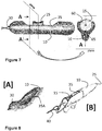
- the actuation button 15 or thumb wheel that fits within the cavity 60 of the cutout 35 may include a tactile bump 65, which can be seen in the cross-section of the actuation button 15 shown in the plane (A) view of Figure 7 . This tactile bump 65 may assist the user in determining the orientation of the attached medical device 40.
- this longitudinal slot may be in the shape of a droplet 35A as shown in Figure 8A .
- the droplet shaped cutout 35A may vary in size provided the actuation button 15 is secured and cannot slip out of the cavity 60 formed by the cutout 35A ( Figure 8B ).
- the locking mechanism 20 may include a locking ring 20A configured to be either be in an unlocked position or a locked position.
- the actuation button 15 may be moved ( Figure 9A ).
- the locking ring 20A is in the locked position, the actuation button 15 is prevented from moving ( Figure 9B ).
- the locking ring 20A may include at least one slit 67 that allows one portion of the locking ring 20A-1 to abut against the actuation button 15 when the locking ring 20A is rotated into the locked position ( Figure 9C ).
- FIG. 9B Another portion of the locking ring 20A-2 is located such that it grips or holds a portion of the elongated handle body 10 ( Figure 9B ).
- Such a locking mechanism 20 may resist inadvertent or accidental movement or retraction of the actuation button 15 or other components in the multipurpose handle 5 during packaging, sterilization, shipping, storage, handling, and preparation for use.
- the elongated handle body 10 may comprise a fin 11 aligned with the longitudinal axis (I) of the elongated handle body 10.
- This fin 11 further comprise a hole 13 located in a position that is easily accessible by the index finger of the user during the operation of the medical device delivery system 1 (see Figure 10 ).
- the difference ( ⁇ ) between the longitudinal axis (I) of the elongated handle body 10 and the longitudinal axis (II) of the locking member 20 causes the locking member 30 to rotate into the elongated handle body 10 of the multipurpose handle 5 (see Figure 11 ).
- the locking member 20 may include one or more fins 21 to assist in gripping the mechanism in order to scroll or rotate the member between locked and unlocked positions.
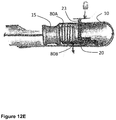
- a sliding locking button 23 is utilized. This locking button 23 slides against a portion of the actuation button 15 in order to prevent movement thereof when in the locked position. Alternatively, the locking button 23 abuts against a side and/or a face 15A of the actuation button 15 or thumb wheel. Alternatively, the locking member 20 or button 23 makes contact with the distal face 15A of the actuation button 15 or thumb wheel. The locking button 23 may slide in an opposite direction in order to unlock and allow the actuation button 15 to move. In this embodiment, the index finger 4 of the user may, together with the thumb finger provide greater control of the actuation button 15.
- the locking button 23 is shown to abut against a face 15A of the actuation button 15.
- the fin 11 in contact with the user's middle or index finger 4 is capable of movement (m) causing the locking button 23 to engage the face 15A of the actuation button 15 in order to establish a locked position.
- the locking button 23 may be held in place through the use of one or more fasteners 24 formed as part of the locking button 23.
- the actuation button 15 may slide over a projection 10B arising from a wall of the elongate handle body 10 to create a locked position. In this locked position, the actuation button 15 is held in place by a spring 70. The actuation button 15 may be released, thereby, creating an unlocked position through the use of the locking button 23.
- the locking button 23 in this case is a push button that overcomes the spring 70 retention and moves the actuation button 15 past the projection 10B in the wall of the elongate body handle 10.
- FIG. 12D Another form of the locking member 20 is shown in Figure 12D in which the locking button 23 is a spring-loaded lever capable of being pivoted near its fulcrum point 75.
- a spring 71 is positioned such that the locking button 23 is held in a locked position by the spring 71 forcing the lever to contact a face 15A of the actuation button 15. The user is able to release the actuation button 15 by pushing on the locking button 23, thereby overcoming the spring 71 retention and creating an unlocked position.
- the multipurpose handle 1 may include the capability of providing variable locking positions during the operation of the delivery system.
- Variable locking positons may be created, without limitation, through the use of a plurality of splines, ridges, or teeth 80A located in the surface of the actuation button 15 that are appropriately mated or meshed with a plurality of grooves 80B formed in the locking member 20 or vice versa.
- the alignment or meshing of the splines 80A and the grooves 80B creates a locked position that prevents movement of the actuation button 15.
- the different number of splines 80A and grooves 80B that may be meshed or mated together establish variability in the position of the actuation button 15.
- the locking member 20 may include a locking button 23 in which pushing upon the locking button 23 causes the splines 80A and grooves 80B to separate, thereby, creating an unlocked position allowing the actuation button 15 to move.
- the locking member 20 may be integrated with the fin 11 formed as part of the elongate handle body 10.
- the locking member 20 includes a pivot point 90 that allows the index finger of the user to apply pressure and push the locking member 20 into contact with the surface of a face 15A of the actuation button 15.
- the locking member 20 acts similar to a lever that is typically in an unlocked position and upon the application of external force or pressure by the user is forced into a locked position.
- the locking button 23 comprises at least one protrusion 93 located on each side of the locking button 23 in order to hold the button 23 in place and prevent the button 23 from being removed (i.e., falling) through the opening present in the elongated handle body 10.
- These protrusions 93 may also act as the pivot point 90A with respect to axis (III) in order for the locking button to establish a locked position and unlocked position.
- the locking button 23 may also be ergonomically curved 95 so that it more appropriately fits the index finger of the user.
- a locking button 23 is forced to abut against a face 15A of the actuation button, thereby, creating a locked position.
- the locking button 23 may be spring-loaded in that a spring forces the multipurpose handle to be in an unlocked or locked state in the absence of pressure applied by the user to the locking button 23.
- the spring 72 as shown in Figure 15 may provide a sensible and/or audible click associated with locking/unlocking the button 23. In the absence of pressure, the button 23 remains in the state in which it was left with subsequent locking or unlocking having to be done manually. In other words, an external force applied to the locking member that overcomes the force of the spring is able to cause the locking member to move from the unlocked position to the locked position or from the locked position to the unlocked position.
- the multipurpose handle includes an elongate handle body, an actuation button, and a locking member.
- the elongate handle body has a proximal end, and a distal end, and defines a longitudinal axis therebetween.
- the elongate body may further include a cutout that creates a movement space therein in which the actuation button is disposed and is connected to a medical device.
- the actuation button may be moveable within the cutout along the longitudinal axis and rotatable within the cutout.
- the locking member may be connected to the elongate handle body and movable between a locked position and unlocked position.
- the medical device delivery system comprises an outer sheath, a medical device, and a multipurpose handle.
- the medical device is located at least partially within, alternatively, entirely within the outer sheath in an initial configuration ready for deployment.
- the outer sheath may be a catheter capable of holding and protecting the medical device while it is pushed endoluminally through a patient's vasculature to a remote treatment or targeted site.
- the outer sheath or catheter is advantageously as small in diameter as possible for a given application, in order to improve endovascular movement and hold the medical device properly in position until its deployment.
- the outer sheath may accommodate the use of a guide wire for tracking the delivery of the medical device to the desired or targeted position.
- the type of medical device is not restricted and may take the form of any known devices, including but not limited to, stents, embolic coils, and vena cava filters.
- a medical device delivery system that incorporates a multipurpose handle as described herein to deliver or retrieve a medical device from a desired or targeted site within a vasculature of a patient's body is believed to be within the scope of the present invention.
- the patient may be deceased (i.e. a cadaver) such that this use does not comprise a method of treatment of the human or animal body by surgery or therapy.
- the multipurpose handle provides the user with control over longitudinal movement together with scrolling rotation of the attached medical device. The user may utilize his/her thumb and index finger on a single hand to accomplish such longitudinal and rotational movements.
Landscapes
- Health & Medical Sciences (AREA)
- Engineering & Computer Science (AREA)
- Biomedical Technology (AREA)
- Life Sciences & Earth Sciences (AREA)
- General Health & Medical Sciences (AREA)
- Veterinary Medicine (AREA)
- Public Health (AREA)
- Heart & Thoracic Surgery (AREA)
- Vascular Medicine (AREA)
- Animal Behavior & Ethology (AREA)
- Transplantation (AREA)
- Oral & Maxillofacial Surgery (AREA)
- Cardiology (AREA)
- Surgery (AREA)
- Reproductive Health (AREA)
- Nuclear Medicine, Radiotherapy & Molecular Imaging (AREA)
- Medical Informatics (AREA)
- Molecular Biology (AREA)
- Media Introduction/Drainage Providing Device (AREA)
- Surgical Instruments (AREA)
- Infusion, Injection, And Reservoir Apparatuses (AREA)
Applications Claiming Priority (1)
| Application Number | Priority Date | Filing Date | Title |
|---|---|---|---|
| US201962791948P | 2019-01-14 | 2019-01-14 |
Publications (1)
| Publication Number | Publication Date |
|---|---|
| EP3679889A1 true EP3679889A1 (de) | 2020-07-15 |
Family
ID=69159686
Family Applications (1)
| Application Number | Title | Priority Date | Filing Date |
|---|---|---|---|
| EP20151467.6A Pending EP3679889A1 (de) | 2019-01-14 | 2020-01-13 | Mehrzweckgriff |
Country Status (3)
| Country | Link |
|---|---|
| US (3) | US11684501B2 (de) |
| EP (1) | EP3679889A1 (de) |
| CN (2) | CN119257789A (de) |
Cited By (1)
| Publication number | Priority date | Publication date | Assignee | Title |
|---|---|---|---|---|
| WO2023183253A1 (en) * | 2022-03-23 | 2023-09-28 | Edwards Lifesciences Corporation | Delivery apparatus and methods for implanting prosthetic heart valves |
Families Citing this family (10)
| Publication number | Priority date | Publication date | Assignee | Title |
|---|---|---|---|---|
| US9867931B2 (en) | 2013-10-02 | 2018-01-16 | Cook Medical Technologies Llc | Therapeutic agents for delivery using a catheter and pressure source |
| US11684501B2 (en) * | 2019-01-14 | 2023-06-27 | Cook Medical Technologies Llc | Multipurpose handle |
| US20210338984A1 (en) * | 2020-05-01 | 2021-11-04 | Robert Booker | Deflectable catheter systems and methods of use |
| EP4161346A2 (de) | 2020-06-05 | 2023-04-12 | Cook Medical Technologies LLC | Medizinische anwendungen zur verabreichung von therapeutischen mitteln |
| CN115916067B (zh) * | 2020-11-18 | 2025-03-14 | 野村Unison股份有限公司 | 手术器械 |
| CN113100851B (zh) * | 2021-04-29 | 2022-06-03 | 武汉联影智融医疗科技有限公司 | 控制手柄及缝合器 |
| WO2023287654A1 (en) | 2021-07-14 | 2023-01-19 | Cook Medical Technologies, LLC | Systems and methods for preventing clogging of a delivery system |
| US12575853B2 (en) * | 2021-07-15 | 2026-03-17 | Cook Medical Technologies Llc | Multipurpose handles and medical snare or other devices incorporating them |
| US12496429B2 (en) | 2022-10-18 | 2025-12-16 | Cook Medical Technologies Llc | Systems and methods for delivering pressurized fluid to a target site alone or in conjunction with therapeutic agents |
| CN116712179B (zh) * | 2023-05-24 | 2026-04-07 | 宁波睿达医疗器械有限公司 | 一种操作手柄和手术机器人 |
Citations (3)
| Publication number | Priority date | Publication date | Assignee | Title |
|---|---|---|---|---|
| EP1302178A2 (de) * | 2001-10-12 | 2003-04-16 | Cordis Corporation | Handgriffentfaltungsmechanismus für medizinische Vorrichtung und Verfahren |
| US6572643B1 (en) * | 2000-07-19 | 2003-06-03 | Vascular Architects, Inc. | Endoprosthesis delivery catheter assembly and method |
| WO2012036741A2 (en) * | 2010-09-17 | 2012-03-22 | St. Jude Medical, Cardiology Division, Inc. | Staged deployment devices and methods for transcatheter heart valve delivery |
Family Cites Families (71)
| Publication number | Priority date | Publication date | Assignee | Title |
|---|---|---|---|---|
| US5066295A (en) * | 1986-05-13 | 1991-11-19 | Mill-Rose Laboratories, Inc. | Rotatable surgical snare |
| US4799496A (en) * | 1987-06-03 | 1989-01-24 | Lake Region Manufacturing Company, Inc. | Guide wire handle |
| US5013300A (en) * | 1989-03-09 | 1991-05-07 | Williams James D | Apparatus for suction lipectomy surgery |
| US5707376A (en) * | 1992-08-06 | 1998-01-13 | William Cook Europe A/S | Stent introducer and method of use |
| US5613973A (en) * | 1995-03-10 | 1997-03-25 | Wilson Greatbatch Ltd. | Laraposcopic surgical grasper having an attachable strap |
| US6248122B1 (en) * | 1999-02-26 | 2001-06-19 | Vascular Architects, Inc. | Catheter with controlled release endoluminal prosthesis |
| US6235026B1 (en) | 1999-08-06 | 2001-05-22 | Scimed Life Systems, Inc. | Polypectomy snare instrument |
| US6258101B1 (en) * | 2000-03-24 | 2001-07-10 | Lacey Manufacturing Company, Inc. | Instrument for deploying surgical devices |
| US6602262B2 (en) | 2000-06-02 | 2003-08-05 | Scimed Life Systems, Inc. | Medical device having linear to rotation control |
| US8021372B2 (en) | 2001-07-05 | 2011-09-20 | Annex Medical, Inc. | Medical retrieval device with independent rotational means |
| US6866669B2 (en) | 2001-10-12 | 2005-03-15 | Cordis Corporation | Locking handle deployment mechanism for medical device and method |
| US6652537B2 (en) | 2001-12-12 | 2003-11-25 | C. R. Bard, Inc. | Articulating stone basket |
| US7662128B2 (en) | 2002-12-23 | 2010-02-16 | Salcudean Septimiu E | Steerable needle |
| US7758625B2 (en) | 2003-09-12 | 2010-07-20 | Abbott Vascular Solutions Inc. | Delivery system for medical devices |
| US7824443B2 (en) | 2003-12-23 | 2010-11-02 | Sadra Medical, Inc. | Medical implant delivery and deployment tool |
| IL160517A0 (en) | 2004-02-23 | 2004-07-25 | Roei Medical Technologies Ltd | A working tool for medical purposes having a rotating blade of adjustable size and a method therefor |
| US7637916B2 (en) | 2004-06-01 | 2009-12-29 | Medtronic, Inc. | Medical electrical lead implant tool |
| US20050273151A1 (en) | 2004-06-04 | 2005-12-08 | John Fulkerson | Stent delivery system |
| US20070255289A1 (en) | 2006-04-27 | 2007-11-01 | Granit Medical Innovation, Inc. | Endoscopic instrument with rotational and axial motion control |
| US7758593B2 (en) | 2006-05-04 | 2010-07-20 | Ethicon Endo-Surgery, Inc. | Medical instrument handle and medical instrument having same |
| USD598543S1 (en) | 2006-06-13 | 2009-08-18 | Angiomed Gmbh & Co. Medizintechnik Kg | Handle for a medical delivery device |
| US8858567B2 (en) | 2006-10-14 | 2014-10-14 | Rafic Saleh | Surgical retrieval device and method |
| US20090024084A1 (en) | 2007-07-16 | 2009-01-22 | Peritec Biosciences Ltd. | Multi-lumen catheter assembly and method of providing relative motion thereto |
| WO2009079509A2 (en) | 2007-12-18 | 2009-06-25 | Boston Scientific Scimed, Inc. | Multi-functional medical device |
| US20090210046A1 (en) | 2008-02-20 | 2009-08-20 | Abbott Laboratories | Handle assembly for a delivery system |
| US20110071490A1 (en) | 2009-09-18 | 2011-03-24 | Kassab Interventional Devices, Llc ("Kids") | System and procedure for placing a medical device proximate an ostial lesion using a catheter assembly |
| US20170080185A1 (en) | 2009-09-18 | 2017-03-23 | Kassab Kughn Endovascular Devices Llc | System and procedure for placing a medical device proximate an ostial lesion using a catheter assembly |
| WO2011038017A1 (en) | 2009-09-22 | 2011-03-31 | Penumbra, Inc. | Manual actuation system for deployment of implant |
| US9339631B2 (en) * | 2009-09-25 | 2016-05-17 | Boston Scientific Scimed, Inc. | Locking mechanism for a medical device |
| US8585750B2 (en) | 2010-04-20 | 2013-11-19 | Medtronic Vascular, Inc. | Retraction mechanism and method for graft cover retraction |
| JP5846505B2 (ja) | 2010-05-14 | 2016-01-20 | メドトロニック ヴァスキュラー インコーポレイテッド | 補綴具送達システム用カテーテルハンドル |
| CN103079500B (zh) | 2010-09-01 | 2016-09-21 | 美敦力公司 | 单手操作的展开手柄 |
| EP2428189A1 (de) | 2010-09-10 | 2012-03-14 | Symetis Sa | Kathetereinbringungssystem für ein Stentventil |
| GB2485569A (en) | 2010-11-19 | 2012-05-23 | Gyrus Medical Ltd | Bipolar snare with rotatable guide member |
| KR101298690B1 (ko) | 2011-01-25 | 2013-08-21 | 신경민 | 의료용 스네어 |
| JP6026513B2 (ja) * | 2011-05-13 | 2016-11-16 | スパイレーション インコーポレイテッド ディー ビー エイ オリンパス レスピラトリー アメリカ | 展開カテーテル |
| US8715302B2 (en) | 2011-06-17 | 2014-05-06 | Estech, Inc. (Endoscopic Technologies, Inc.) | Left atrial appendage treatment systems and methods |
| US9060860B2 (en) | 2011-08-18 | 2015-06-23 | St. Jude Medical, Cardiology Division, Inc. | Devices and methods for transcatheter heart valve delivery |
| EP2757979B1 (de) | 2011-09-23 | 2018-09-19 | Cook Medical Technologies LLC | Schlingensystem |
| EP2919729B1 (de) | 2012-11-15 | 2017-05-31 | Cork Institute Of Technology | Paukenröhrchen und einführungsvorrichtung |
| US9308349B2 (en) | 2013-02-08 | 2016-04-12 | Vention Medical Advanced Components, Inc. | Universal catheter handle |
| FR3004331B1 (fr) * | 2013-04-11 | 2015-04-17 | Maurice Marle Ets | Manche amovible muni d'un dispositif d'assemblage demontable |
| US20140336676A1 (en) | 2013-05-08 | 2014-11-13 | Sentreheart, Inc. | Tissue ligation devices and methods therefor |
| EP3010430A1 (de) | 2013-06-21 | 2016-04-27 | Boston Scientific Scimed, Inc. | Resektionsvorrichtungen und zugehörige verfahren zum einsetzen |
| CN106163422B (zh) | 2013-12-30 | 2020-10-09 | 阿特瑞克尔公司 | 用于左心耳封堵的系统和方法 |
| DE102014101603A1 (de) | 2014-02-10 | 2015-08-13 | Karl Storz Gmbh & Co. Kg | Chirurgisches Instrument, Handhabe, Bedienverfahren und Zerlegeverfahren für selbiges |
| US10226368B2 (en) | 2014-04-23 | 2019-03-12 | Medtronic Vascular, Inc. | Delivery system for a retractable outer sheath |
| CN106456343B (zh) * | 2014-05-21 | 2018-10-16 | 波士顿科学医学有限公司 | 支架传送系统 |
| US9737688B2 (en) | 2014-09-12 | 2017-08-22 | Freudenberg Medical, Llc | Modular handle assembly for a steerable catheter |
| US10098768B2 (en) * | 2014-09-15 | 2018-10-16 | Cook Medical Technologies Llc | Ratchet operated vascular intervention device delivery system |
| EP4088691B1 (de) | 2014-10-13 | 2025-08-06 | Boston Scientific Medical Device Limited | Kathetereinführungssystem für eine stentklappe |
| WO2016063593A1 (ja) | 2014-10-23 | 2016-04-28 | 株式会社カネカ | 操作ハンドル及びステントデリバリーシステム |
| US10143826B2 (en) | 2014-10-31 | 2018-12-04 | SonoStik LLC | Wire introduction device for introducing guide wire |
| US10292850B2 (en) | 2014-11-04 | 2019-05-21 | Cook Medical Technologies Llc | Deployment handle for a prosthesis delivery device |
| US10159587B2 (en) | 2015-01-16 | 2018-12-25 | Boston Scientific Scimed, Inc. | Medical device delivery system with force reduction member |
| US10588744B2 (en) | 2015-09-04 | 2020-03-17 | Edwards Lifesciences Corporation | Delivery system for prosthetic heart valve |
| WO2017132065A1 (en) * | 2016-01-27 | 2017-08-03 | Henry Ford Health System | Snare assembly portion, an endoscopic catheter assembly and a method for utilizing the same |
| CN109069799B (zh) | 2016-04-08 | 2021-07-16 | 圣犹达医疗用品心脏病学部门有限公司 | 标测可调环圈导管手柄 |
| US10888349B2 (en) | 2016-07-27 | 2021-01-12 | Boston Scientific Scimed, Inc. | Medical device handles and related methods |
| US11304747B2 (en) | 2016-11-16 | 2022-04-19 | Boston Scientific Scimed, Inc. | Rotatable snares and related methods |
| US20180168679A1 (en) | 2016-12-16 | 2018-06-21 | Hyung Jong Oh | Surgical snare instrument |
| US10973634B2 (en) | 2017-04-26 | 2021-04-13 | Edwards Lifesciences Corporation | Delivery apparatus for a prosthetic heart valve |
| US10874839B2 (en) | 2017-07-13 | 2020-12-29 | Acclarent, Inc. | Adjustable instrument for dilation of anatomical passageway |
| DE102017010535A1 (de) | 2017-11-14 | 2019-05-16 | Uromed Kurt Drews Kg | Medizinisches Gerät zum Bewegen eines medizinischen Instruments |
| CA3085339A1 (en) | 2017-12-14 | 2019-06-20 | Carl Zeiss Meditec Cataract Technology Inc. | Devices and methods for ocular surgery |
| US20190388144A1 (en) | 2018-06-25 | 2019-12-26 | Wei Shen | Medical instrument for endoscopic mucosal resection and endoscopic submucosal dissection |
| US11185667B2 (en) | 2018-07-19 | 2021-11-30 | Boston Scientific Scimed, Inc. | Medical device handle and method of use |
| IL281028B2 (en) | 2018-08-23 | 2024-02-01 | Nuvera Medical Inc | Standards, systems and methods of use and production for the guidance of medical devices |
| US11684501B2 (en) * | 2019-01-14 | 2023-06-27 | Cook Medical Technologies Llc | Multipurpose handle |
| IL266653B (en) | 2019-05-15 | 2020-08-31 | Cardiovia Ltd | Non-penetrating tissue separator |
| US11364365B2 (en) | 2019-05-18 | 2022-06-21 | Cairdac | Delivery system with an operating handle controlling a steerable catheter for the implantation of a leadless cardiac capsule |
-
2020
- 2020-01-10 US US16/739,497 patent/US11684501B2/en active Active
- 2020-01-13 EP EP20151467.6A patent/EP3679889A1/de active Pending
- 2020-01-14 CN CN202411391472.4A patent/CN119257789A/zh active Pending
- 2020-01-14 CN CN202010037062.5A patent/CN111434319B/zh active Active
-
2023
- 2023-06-20 US US18/337,733 patent/US12396872B2/en active Active
-
2025
- 2025-08-11 US US19/296,303 patent/US20250360011A1/en active Pending
Patent Citations (3)
| Publication number | Priority date | Publication date | Assignee | Title |
|---|---|---|---|---|
| US6572643B1 (en) * | 2000-07-19 | 2003-06-03 | Vascular Architects, Inc. | Endoprosthesis delivery catheter assembly and method |
| EP1302178A2 (de) * | 2001-10-12 | 2003-04-16 | Cordis Corporation | Handgriffentfaltungsmechanismus für medizinische Vorrichtung und Verfahren |
| WO2012036741A2 (en) * | 2010-09-17 | 2012-03-22 | St. Jude Medical, Cardiology Division, Inc. | Staged deployment devices and methods for transcatheter heart valve delivery |
Cited By (1)
| Publication number | Priority date | Publication date | Assignee | Title |
|---|---|---|---|---|
| WO2023183253A1 (en) * | 2022-03-23 | 2023-09-28 | Edwards Lifesciences Corporation | Delivery apparatus and methods for implanting prosthetic heart valves |
Also Published As
| Publication number | Publication date |
|---|---|
| US20250360011A1 (en) | 2025-11-27 |
| CN111434319B (zh) | 2024-10-25 |
| US11684501B2 (en) | 2023-06-27 |
| US20200222218A1 (en) | 2020-07-16 |
| CN111434319A (zh) | 2020-07-21 |
| US20240277503A1 (en) | 2024-08-22 |
| CN119257789A (zh) | 2025-01-07 |
| US12396872B2 (en) | 2025-08-26 |
Similar Documents
| Publication | Publication Date | Title |
|---|---|---|
| US12396872B2 (en) | Multipurpose handle | |
| US12408918B2 (en) | Anchor magazine | |
| US8535366B2 (en) | Implantable device delivery system handle and method of use | |
| EP1380271B1 (de) | Einführbesteck mit Sperrgriff für medizinisches Gerät | |
| JP7499897B2 (ja) | セルフロック式、マルチポジション、およびスライドボタン式の直線的に作動可能な格納式ブレードまたはフックを備える軟部組織切断器具 | |
| JP7203922B2 (ja) | 格納式ブレードまたはフック付き軟組織切断機器 | |
| US12575853B2 (en) | Multipurpose handles and medical snare or other devices incorporating them | |
| EP2535009B1 (de) | Tastenauslösegriff | |
| US20130158516A1 (en) | Variable Stiffness Guidewire Systems | |
| AU2011296277A1 (en) | Single handed deployment handle | |
| US6979340B2 (en) | Single use, self-contained twist resistant surgical knife | |
| EP3700476B1 (de) | Kathetersystem zur stentfreisetzung mit langsamer geschwindigkeitssteuerung über stift und schlitz mit schneller geschwindigkeitssteuerlasche |
Legal Events
| Date | Code | Title | Description |
|---|---|---|---|
| PUAI | Public reference made under article 153(3) epc to a published international application that has entered the european phase |
Free format text: ORIGINAL CODE: 0009012 |
|
| STAA | Information on the status of an ep patent application or granted ep patent |
Free format text: STATUS: THE APPLICATION HAS BEEN PUBLISHED |
|
| AK | Designated contracting states |
Kind code of ref document: A1 Designated state(s): AL AT BE BG CH CY CZ DE DK EE ES FI FR GB GR HR HU IE IS IT LI LT LU LV MC MK MT NL NO PL PT RO RS SE SI SK SM TR |
|
| AX | Request for extension of the european patent |
Extension state: BA ME |
|
| STAA | Information on the status of an ep patent application or granted ep patent |
Free format text: STATUS: REQUEST FOR EXAMINATION WAS MADE |
|
| 17P | Request for examination filed |
Effective date: 20210115 |
|
| RBV | Designated contracting states (corrected) |
Designated state(s): AL AT BE BG CH CY CZ DE DK EE ES FI FR GB GR HR HU IE IS IT LI LT LU LV MC MK MT NL NO PL PT RO RS SE SI SK SM TR |
|
| STAA | Information on the status of an ep patent application or granted ep patent |
Free format text: STATUS: EXAMINATION IS IN PROGRESS |
|
| 17Q | First examination report despatched |
Effective date: 20240614 |
|
| 17Q | First examination report despatched |
Effective date: 20240625 |