EP3679912A2 - Rollstuhl zur überwindung von hindernissen - Google Patents
Rollstuhl zur überwindung von hindernissen Download PDFInfo
- Publication number
- EP3679912A2 EP3679912A2 EP19215744.4A EP19215744A EP3679912A2 EP 3679912 A2 EP3679912 A2 EP 3679912A2 EP 19215744 A EP19215744 A EP 19215744A EP 3679912 A2 EP3679912 A2 EP 3679912A2
- Authority
- EP
- European Patent Office
- Prior art keywords
- wheelchair
- wheelchair according
- rollers
- seat
- chassis
- Prior art date
- Legal status (The legal status is an assumption and is not a legal conclusion. Google has not performed a legal analysis and makes no representation as to the accuracy of the status listed.)
- Granted
Links
Images


Classifications
-
- A—HUMAN NECESSITIES
- A61—MEDICAL OR VETERINARY SCIENCE; HYGIENE
- A61G—TRANSPORT, PERSONAL CONVEYANCES, OR ACCOMMODATION SPECIALLY ADAPTED FOR PATIENTS OR DISABLED PERSONS; OPERATING TABLES OR CHAIRS; CHAIRS FOR DENTISTRY; FUNERAL DEVICES
- A61G5/00—Chairs or personal conveyances specially adapted for patients or disabled persons, e.g. wheelchairs
- A61G5/06—Chairs or personal conveyances specially adapted for patients or disabled persons, e.g. wheelchairs with obstacle mounting facilities, e.g. for climbing stairs, kerbs or steps
- A61G5/061—Chairs or personal conveyances specially adapted for patients or disabled persons, e.g. wheelchairs with obstacle mounting facilities, e.g. for climbing stairs, kerbs or steps for climbing stairs
-
- A—HUMAN NECESSITIES
- A61—MEDICAL OR VETERINARY SCIENCE; HYGIENE
- A61G—TRANSPORT, PERSONAL CONVEYANCES, OR ACCOMMODATION SPECIALLY ADAPTED FOR PATIENTS OR DISABLED PERSONS; OPERATING TABLES OR CHAIRS; CHAIRS FOR DENTISTRY; FUNERAL DEVICES
- A61G5/00—Chairs or personal conveyances specially adapted for patients or disabled persons, e.g. wheelchairs
- A61G5/06—Chairs or personal conveyances specially adapted for patients or disabled persons, e.g. wheelchairs with obstacle mounting facilities, e.g. for climbing stairs, kerbs or steps
- A61G5/068—Chairs or personal conveyances specially adapted for patients or disabled persons, e.g. wheelchairs with obstacle mounting facilities, e.g. for climbing stairs, kerbs or steps with extensible supports pushing upwards, e.g. telescopic legs
-
- A—HUMAN NECESSITIES
- A61—MEDICAL OR VETERINARY SCIENCE; HYGIENE
- A61G—TRANSPORT, PERSONAL CONVEYANCES, OR ACCOMMODATION SPECIALLY ADAPTED FOR PATIENTS OR DISABLED PERSONS; OPERATING TABLES OR CHAIRS; CHAIRS FOR DENTISTRY; FUNERAL DEVICES
- A61G5/00—Chairs or personal conveyances specially adapted for patients or disabled persons, e.g. wheelchairs
- A61G5/06—Chairs or personal conveyances specially adapted for patients or disabled persons, e.g. wheelchairs with obstacle mounting facilities, e.g. for climbing stairs, kerbs or steps
- A61G5/063—Chairs or personal conveyances specially adapted for patients or disabled persons, e.g. wheelchairs with obstacle mounting facilities, e.g. for climbing stairs, kerbs or steps with eccentrically mounted wheels
-
- A—HUMAN NECESSITIES
- A61—MEDICAL OR VETERINARY SCIENCE; HYGIENE
- A61G—TRANSPORT, PERSONAL CONVEYANCES, OR ACCOMMODATION SPECIALLY ADAPTED FOR PATIENTS OR DISABLED PERSONS; OPERATING TABLES OR CHAIRS; CHAIRS FOR DENTISTRY; FUNERAL DEVICES
- A61G2203/00—General characteristics of devices
- A61G2203/30—General characteristics of devices characterised by sensor means
- A61G2203/40—General characteristics of devices characterised by sensor means for distance
-
- A—HUMAN NECESSITIES
- A61—MEDICAL OR VETERINARY SCIENCE; HYGIENE
- A61G—TRANSPORT, PERSONAL CONVEYANCES, OR ACCOMMODATION SPECIALLY ADAPTED FOR PATIENTS OR DISABLED PERSONS; OPERATING TABLES OR CHAIRS; CHAIRS FOR DENTISTRY; FUNERAL DEVICES
- A61G2203/00—General characteristics of devices
- A61G2203/30—General characteristics of devices characterised by sensor means
- A61G2203/42—General characteristics of devices characterised by sensor means for inclination
-
- A—HUMAN NECESSITIES
- A61—MEDICAL OR VETERINARY SCIENCE; HYGIENE
- A61G—TRANSPORT, PERSONAL CONVEYANCES, OR ACCOMMODATION SPECIALLY ADAPTED FOR PATIENTS OR DISABLED PERSONS; OPERATING TABLES OR CHAIRS; CHAIRS FOR DENTISTRY; FUNERAL DEVICES
- A61G5/00—Chairs or personal conveyances specially adapted for patients or disabled persons, e.g. wheelchairs
- A61G5/10—Parts, details or accessories
- A61G5/1051—Arrangements for steering
-
- A—HUMAN NECESSITIES
- A61—MEDICAL OR VETERINARY SCIENCE; HYGIENE
- A61G—TRANSPORT, PERSONAL CONVEYANCES, OR ACCOMMODATION SPECIALLY ADAPTED FOR PATIENTS OR DISABLED PERSONS; OPERATING TABLES OR CHAIRS; CHAIRS FOR DENTISTRY; FUNERAL DEVICES
- A61G5/00—Chairs or personal conveyances specially adapted for patients or disabled persons, e.g. wheelchairs
- A61G5/10—Parts, details or accessories
- A61G5/1056—Arrangements for adjusting the seat
- A61G5/1075—Arrangements for adjusting the seat tilting the whole seat backwards
-
- B—PERFORMING OPERATIONS; TRANSPORTING
- B62—LAND VEHICLES FOR TRAVELLING OTHERWISE THAN ON RAILS
- B62B—HAND-PROPELLED VEHICLES, e.g. HAND CARTS OR PERAMBULATORS; SLEDGES
- B62B5/00—Accessories or details specially adapted for hand carts
- B62B5/0026—Propulsion aids
- B62B5/0069—Control
-
- B—PERFORMING OPERATIONS; TRANSPORTING
- B62—LAND VEHICLES FOR TRAVELLING OTHERWISE THAN ON RAILS
- B62B—HAND-PROPELLED VEHICLES, e.g. HAND CARTS OR PERAMBULATORS; SLEDGES
- B62B5/00—Accessories or details specially adapted for hand carts
- B62B5/02—Accessories or details specially adapted for hand carts providing for travelling up or down a flight of stairs
Definitions
- the invention relates to a wheelchair for overcoming obstacles, according to the preamble of the independent claim.
- Wheelchairs are known from the prior art that can overcome obstacles such as stairs.
- the patent EP 0100449 shows a wheelchair that can automatically go up and down stairs, characterized in that the chassis has two frames lying parallel to each other, on which a compressed air tank with an associated compressor and piston-cylinder units are arranged such that the frame with the piston Cylinder units in the side projection are adjustable in the manner of a parallelogram linkage. In this way, the seat can maintain its horizontal position with different relative positions.
- the disadvantage is that moving around with the wheelchair described takes time in the case of obstacles with large vertical distances, since the piston-cylinder unit has to be extended and retracted far.
- the safety perception of the wheelchair occupant is significantly reduced by a large distance from the floor surface.
- the wheelchair comprises several rollers to overcome obstacles, in particular steps and stairs.
- the rollers are arranged in at least two rows.
- the rows are arranged on both sides of the wheelchair.
- the wheelchair further comprises a chassis on or in which a seat is arranged.
- the seat is mounted on or in the chassis such that it remains in a substantially horizontal sitting position when an obstacle is overcome.
- Each of the rollers is arranged on the chassis via at least one suspension so that the suspension encloses an angle of ⁇ 90 ° with respect to the tread of a step in the direction of travel.
- rollers in a row have the advantage that, for example, when climbing the stairs of the wheelchair, the first rollers in the direction of travel of the wheelchair can already be raised by means of a guide tube while the following rollers are still in contact with the floor surface. This enables the wheelchair to move stably when overcoming obstacles.
- An angle of ⁇ 90 ° between the suspension of the casters and the step surface of a step in the direction of travel is particularly advantageous since both the seat surface and the center of gravity of the wheelchair are at a relatively short distance from the floor surface.
- the disclosed wheelchair has the advantage that obstacles can be overcome without reducing the safety or the feeling of security of the wheelchair occupant compared to barrier-free movement.
- the wheelchair is preferably motor-operated.
- the advantage of a motorized wheelchair is that the wheelchair occupant can move easily and without outside help.
- the seat is preferably mounted on or in the chassis via a tilting device.
- a permanent horizontal sitting position of the wheelchair occupant is possible by mounting a seat over a tilting device, even on an incline or slope of the floor.
- the tilting device is preferably arranged in such a way that the seat can be moved about an imaginary axis of rotation in approximately half the position of the wheelchair.
- the tilting device is preferably arranged such that the seat can be moved about an imaginary axis of rotation approximately at the level of the rollers.
- the tilting device is preferably operatively connected to an inclination sensor such that the sitting position remains in a preset position, in particular a horizontal position.
- Each roller can preferably be moved individually by means of a power steering.
- the steering system preferably includes steering eccentrics which are connected to one another in opposite directions by means of ropes.
- the suspension on the individual rollers is preferably designed in the form of guide tubes.
- the rollers can be adapted to the topography of the floor.
- the guide tubes can preferably be extended pneumatically, hydraulically or magnetically via a linear drive.
- One or more sensors for topographical determination of the floor are preferably arranged in a front region of the wheelchair.
- the topographical determination of the soil provides information about the soil conditions in advance, which enables predictive control of the castors. This ensures that the wheelchair can move quickly.
- a lifting movement can also be carried out using the topographical determination. In this way, for example, climbing the wheelchair is possible.
- Distance sensors with which the distance from the sensor to the floor can be determined, are preferably arranged in the area of individual, in particular all, rollers.
- the distance sensors determine the distance between the roller and the floor. If this distance increases, the distance is reduced again by extending the guide tubes.
- the distance sensors are preferably arranged in the area of the rollers such that the sensors point in front of the respective roller in the direction of travel to the floor.
- the wheelchair preferably has a control device for one or more drive motors.
- the control device is preferably connected to a reversing camera.
- the reversing camera can also advantageously identify obstacles when reversing.
- FIG. 1 shows an embodiment of a chassis 2 for a wheelchair 1 for overcoming obstacles.
- a seat 20, a tilting device 3, and a side wall 4 on the left and a side wall 4 on the right (not shown) are arranged on the chassis 2.
- the seat 20 comprises a seat surface 21 and an axis through the center of gravity 22 of the seat 20 and one person.
- the tilting device 3 comprises an imaginary axis of rotation 31, a roller guide 32 and a trapezoidal threaded spindle 33.
- the roller guide 32 enables the seat 20 to move about the imaginary axis of rotation 31.
- the trapezoidal threaded spindle 33 adjusts an angle of inclination in accordance with an inclination of a floor surface 30. in this way, the seat 21 is held in a horizontal position even when the floor surface 30 is inclined.
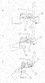
- FIG. 2 A tilting device 3 is shown with a different inclination of a floor surface 30, which is an example of a step down the wheelchair 1.
- the floor surface 30 is in a horizontal position.
- a seat surface 21, a roller guide 32 and a trapezoidal threaded spindle 33 are in the starting position.
- the floor surface 30 is inclined downward by an angle ⁇ 45 ° (for example, descending stairs).
- the seat 21 remains in the starting position, while the roller guide 32 about the imaginary axis of rotation 31 (not shown here, see Fig. 1 ) moves and the trapezoidal screw 33 maintains its angle relative to the inclined floor surface 30.
- Condition C shows an inclination of the floor surface 30 of 45 ° (e.g. maximum inclination of the stairs when descending stairs).
- the seat 21 is in turn in the starting position.
- the roller guide 32 moves further about the imaginary axis of rotation 31 and the trapezoidal threaded spindle 33 maintains its angle relative to the inclined floor surface 30.
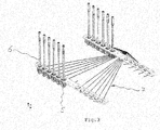
- FIG 3 shows the schematic arrangement of rollers 5 of the wheelchair 1 in two rows.
- Each of the rollers 5 is by means of a suspension 6 in the form of a guide tube in a right or a left side wall 4 (not shown here, see Fig. 1 ) arranged.
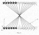
- the rollers are shown in contact with one another by means of a steering system 7.
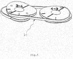
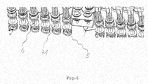
- the steering system 7 comprises steering eccentric 71, which in Fig. 5 are shown schematically and are connected in opposite directions by means of ropes.
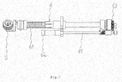
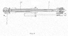
- FIG. 7 and Figure 8 show a roller module comprising a roller 5 and a suspension 6 in the form of a guide tube.
- the suspension 6 comprises a transmission tube 61 which can be extended and retracted linearly with the aid of a motor 61, a gear drive 63 and a lifting spindle 64.
- the rollers 5 can be adapted to the conditions of a floor surface 30.
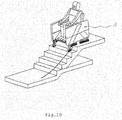
- the Figures 9 and 10th show different positions of a wheelchair 1 when overcoming an obstacle.
- the states AH show the descent of a staircase and the state I the ascent of a staircase. In all the states shown, the seat surface 21 remains in the starting position while the side walls 4 adapt to the inclination of the stairs.
Landscapes
- Health & Medical Sciences (AREA)
- Life Sciences & Earth Sciences (AREA)
- Animal Behavior & Ethology (AREA)
- General Health & Medical Sciences (AREA)
- Public Health (AREA)
- Veterinary Medicine (AREA)
- Handcart (AREA)
- Automatic Cycles, And Cycles In General (AREA)
Abstract
Description
- Die Erfindung betrifft einen Rollstuhl zur Überwindung von Hindernissen, gemäss dem Oberbegriff des unabhängigen Anspruchs.
- Aus dem Stand der Technik sind Rollstühle bekannt, die Hindernisse, wie beispielsweise Treppen, überwinden können.
- Die Patentschrift
EP 0100449 zeigt einen Rollstuhl, der selbsttätig Treppen herauf- und herunterfahren kann, dadurch gekennzeichnet, dass das Fahrgestell zwei parallel zueinander liegende Rahmen aufweist, an denen ein Druckluftbehälter mit zugeordnetem Kompressor und Kolben-Zylinder-Einheiten derart angeordnet sind, dass die Rahmen mit den Kolben-Zylinder-Einheiten in der seitlichen Projektion nach Art eines Parallelogrammgestänges verstellbar sind. So kann der Sitz seine waagrechte Stellung bei unterschiedlichen Relativstellungen beibehalten. - Von Nachteil ist, dass bei Hindernissen mit grossen vertikalen Abständen die Fortbewegung mit dem beschriebenen Rollstuhl Zeit benötigt, da die Kolben-Zylinder-Einheit weit aus- und wieder eingefahren werden muss. Ausserdem wird durch einen grossen Abstand zur Bodenoberfläche das Sicherheitsempfinden des Rollstuhlinsassen deutlich gesenkt.
- Es ist die Aufgabe der vorliegenden Erfindung, einen Rollstuhl zur Überwindung von Hindernissen zu schaffen, welcher die Nachteile des Stands der Technik vermeidet und eine sichere und komfortable Fortbewegung ermöglicht.
- Diese Aufgabe wird durch einen Rollstuhl zur Überwindung von Hindernissen, gemäss den unabhängigen Ansprüchen gelöst. Erfindungsgemäss umfasst der Rollstuhl zur Überwindung von Hindernissen, insbesondere Stufen und Treppen, mehrere Laufrollen. Hierbei sind die Laufrollen in mindestens zwei Reihen angeordnet. Die Reihen wiederum sind an beiden Seiten des Rollstuhls angeordnet. Weiter umfasst der Rollstuhl ein Fahrgestell, an oder in welchem ein Sitz angeordnet ist. Der Sitz ist derart an bzw. in dem Fahrgestell gelagert, dass er bei der Überwindung eines Hindernisses in einer im Wesentlichen waagrechten Sitzposition verbleibt. Jede der Laufrollen ist derart über je mindestens eine Aufhängung an dem Fahrgestell angeordnet, so dass die Aufhängung gegenüber der Trittfläche einer Stufe in Fahrtrichtung einen Winkel von < 90 ° einschliesst.
- Mehrere Laufrollen in einer Reihe haben den Vorteil, dass beispielsweise beim Treppensteigen des Rollstuhls die ersten Laufrollen in Fahrtrichtung des Rollstuhls bereits mittels Führungsrohr angehoben werden können, während die folgenden Laufrollen noch in Kontakt mit der Bodenoberfläche sind. Dies ermöglicht ein stabiles Fortbewegen des Rollstuhls beim Überwinden von Hindernissen.
- Einen Winkel von < 90 ° zwischen der Aufhängung der Laufrollen und der Trittfläche einer Stufe in Fahrtrichtung ist besonders vorteilhaft, da sowohl die Sitzfläche, als auch der Schwerpunkt des Rollstuhls sich in relativ kurzem Abstand zur Bodenoberfläche befinden.
- Der offenbarte Rollstuhl hat den Vorteil, dass Hindernisse überwunden werden können, ohne dabei die Sicherheit oder das Sicherheitsgefühl des Rollstuhlinsassen gegenüber einer barrierefreien Fortbewegung zu verringern.
- Vorzugsweise ist der Rollstuhl motorbetrieben.
- Der Vorteil eines motorbetriebenen Rollstuhls liegt darin, dass der Rollstuhlinsasse sich leicht und ohne fremde Hilfe fortbewegen kann.
- Vorzugsweise ist der Sitz an bzw. im Fahrgestell über eine Kippvorrichtung gelagert.
- Über die Lagerung eines Sitzes über einer Kippvorrichtung ist auch bei einer Steigung oder einem Gefälle des Bodens eine permanente waagrechte Sitzposition des Rollstuhlinsassen möglich.
- Vorzugsweise ist die Kippvorrichtung derart angeordnet, dass der Sitz um eine gedachte Drehachse auf etwa halber Lage des Rollstuhls bewegbar ist.
- Der Vorteil einer solchen Lage der Kippvorrichtung besteht darin, dass der Schwerpunkt des Rollstuhls tief liegt und dadurch der Rollstuhl eine hohe Stabilität aufweist.
- Vorzugsweise ist die Kippvorrichtung derart angeordnet, dass der Sitz um eine gedachte Drehachse etwa auf Höhe der Laufrollen bewegbar ist.
- Dies ist besonders vorteilhaft, da die Lage der Kippvorrichtung in unmittelbarer Laufrollennähe dem Rollstuhl eine besonders hohe Stabilität verleiht.
- Vorzugsweise ist die Kippvorrichtung derart mit einem Neigungssensor wirkverbunden, dass die Sitzposition in einer voreingestellten Position, insbesondere einer waagrechten Position verbleibt.
- Dies ist vorteilhaft, da bei einem Gefälle, wie dies beispielsweise beim Herunterfahren des Rollstuhls von Treppenstufen auftritt, ein Rausrutschen des Rollstuhlinsassen aus dem Sitz vermieden wird.
- Vorzugsweise ist jede Laufrolle einzeln mittels einer Servolenkung bewegbar.
- Dies ist von Vorteil, weil auf diese Art und Weise eine leichte Lenkung der Laufrollen möglich ist.
- Vorzugweise umfasst das Lenksystem Lenkexzenter, welche mittels Seilen gegenläufig miteinander verbunden sind.
- Der Einsatz von Lenkexzentern ermöglicht eine platzsparende Konstruktion.
- Vorzugsweise ist die Aufhängung an den einzelnen Laufrollen in Form von Führungsrohren ausgebildet.
- Da die Führungsrohre ausfahrbar sind, können die Laufrollen an die Topographie des Bodens angepasst werden.
- Vorzugsweise sind die Führungsrohre über einen Linearantrieb pneumatisch, hydraulisch oder magnetisch ausfahrbar.
- Dies ermöglicht ein leichtes und schnelles in Kontakt treten der Laufrollen mit der veränderten Bodenoberfläche.
- Vorzugsweise sind in einem vorderen Bereich des Rollstuhls ein oder mehrere Sensoren zur topographischen Bestimmung des Bodens angeordnet.
- Die topographische Bestimmung des Bodens bietet vorab Informationen über die Bodengegebenheiten, die ein vorausschauendes Ansteuern der Laufrollen ermöglicht. Dadurch wird ein schnelles Fortkommen des Rollstuhls gewährleistet. Ausserdem kann mit Hilfe der topographischen Bestimmung auch eine Hubbewegung durchgeführt werden. Auf diese Art und Weise ist beispielsweise ein Treppensteigen des Rollsuhls möglich.
- Vorzugsweise sind im Bereich einzelner, insbesondere aller Laufrollen Distanzsensoren angeordnet, mit welchen der Abstand vom Sensor zum Boden bestimmbar ist.
- Die Distanzsensoren bestimmen den Abstand zwischen Laufrolle und Boden. Nimmt dieser Abstand zu, dann wird der Abstand durch das Ausfahren der Führungsrohre wieder verringert.
- Vorzugsweise sind die Distanzsensoren derart im Bereich der Laufrollen angeordnet, dass die Sensoren in Fahrtrichtung vor der jeweiligen Laufrolle auf den Boden weisen.
- Auf diese Art und Weise kann vorzeitig eine auftretende Abstandsänderung zwischen Laufrolle und Boden erkannt werden.
- Vorzugsweise weist der Rollstuhl ein Steuerungsgerät für einen oder mehrere Antriebsmotoren auf.
- So ist eine Steuerung, Regelung und Überwachung von einem oder mehreren Antriebsmotoren möglich.
- Vorzugsweise ist das Steuerungsgerät mit einer Rückfahrkamera verbunden.
- Mittels der Rückfahrkamera, können vorteilhafterweise auch Hindernisse beim Rückwärtsfahren erkannt werden.
- Die Erfindung wird im Folgenden anhand von Ausführungsbeispielen in Figuren weiter erläutert. Hierbei zeigen:
- Figur 1:
- Perspektivische Darstellung einer Ausführungsform eines Fahrgestells
- Figur 2:
- Schematische Darstellung einer Kippvorrichtung bei unterschiedlicher Neigung einer Bodenoberfläche
- Figur 3:
- Schematische Darstellung einer Anordnung von Laufrollen
- Figur 4:
- Schematische Darstellung einer Lenkgeometrie
- Figur 5:
- Schematische Darstellung von Lenkexzentern
- Figur 6:
- Schematische Darstellung einer Anordnung von Lenkexzentern an einer Aufhängung
- Figur 7:
- Schematische Darstellung einer Aufhängung
- Figur 8:
- Schematische Darstellung eines Längsschnitts einer Aufhängung
- Figur 9:
- Darstellung unterschiedlicher Zustände eines Rollstuhls beim Überwinden von Treppen
- Figur 10:
- Schematische Darstellung eines Rollstuhls beim Überwinden eines Hindernisses
-
Figur 1 zeigt eine Ausführungsform eines Fahrgestells 2 für einen Rollstuhl 1 zur Überwindung von Hindernissen. An dem Fahrgestell 2 sind ein Sitz 20, eine Kippvorrichtung 3, und eine Seitenwand 4 links und eine Seitenwand 4 rechts (nicht gezeigt) angeordnet. Der Sitz 20 umfasst eine Sitzfläche 21 und eine Achse durch den Schwerpunkt 22 von Sitz 20 und einer Person. Die Kippvorrichtung 3 umfasst eine gedachte Drehachse 31, eine Rollenführung 32 und eine Trapezgewindespindel 33. Die Rollenführung 32 ermöglicht eine Bewegung des Sitzes 20 um die gedachte Drehachse 31. Die Trapezgewindespindel 33 stellt entsprechend einer Neigung einer Bodenoberfläche 30 einen Neigungswinkel ein. auf diese Art und Weise wird die Sitzfläche 21 auch bei Neigung der Bodenoberfläche 30 in einer waagrechten Position gehalten. - In
Figur 2 wird eine Kippvorrichtung 3 bei unterschiedlicher Neigung einer Bodenoberfläche 30 dargestellt, welche beispielhaft für einen Treppenabstieg des Rollstuhls 1 ist. In Zustand A ist die Bodenoberfläche 30 in waagrechter Lage. Eine Sitzfläche 21, eine Rollenführung 32 und eine Trapezgewindespindel 33 befinden sich in Ausgangslage. In Zustand B ist die Bodenoberfläche 30 um einen Winkel < 45 ° nach unten geneigt (Bsp. Treppenabstieg). Die Sitzfläche 21 bleibt in der Ausgangslage, während sich die Rollenführung 32 um die gedachte Drehachse 31 (hier nicht gezeigt, sieheFig. 1 ) bewegt und die Trapezgewindespindel 33 ihren Winkel relativ zur geneigten Bodenoberfläche 30 beibehält. Zustand C zeigt eine Neigung der Bodenoberfläche 30 von 45° (Bsp. maximale Neigung der Treppe beim Treppenabstieg). Die Sitzfläche 21 befindet sich wiederum in der Ausgangslage. Die Rollenführung 32 bewegt sich weiter um die gedachte Drehachse 31 und die Trapezgewindespindel 33 behält ihren Winkel relativ zur geneigten Bodenoberfläche 30 bei. -
Figur 3 zeigt die schematische Anordnung von Laufrollen 5 des Rollstuhls 1 in zwei Reihen. Jede der Laufrollen 5 ist mittels einer Aufhängung 6 in Form eines Führungsrohres in einer rechten oder einer linken Seitenwand 4 (hier nicht gezeigt, sieheFig. 1 ) angeordnet. - Wie in
Figur 3 und4 gezeigt stehen die Rollen mittels eines Lenksystems 7 miteinander in Kontakt. Das Lenksystem 7 umfasst Lenkexzenter 71, die inFig. 5 schematisch dargestellt sind und mittels Seilen gegenläufig miteinander verbunden sind. - In
Figur 6 ist eine Anordnung der Lenkexzenter 71 zur Lenkung der Laufrollen 5 an den Führungsrohren 6 gezeigt. -
Figur 7 undFigur 8 zeigen ein Rollenmodul umfassend eine Laufrolle 5 und eine Aufhängung 6 in Form eines Führungsrohres. Die Aufhängung 6 umfasst ein Übertragungsrohr 61, welches mit Hilfe eines Motors 61, eines Zahnradantriebs 63 und einer Hubspindel 64, linear angetrieben, aus- und eingefahren werden kann. Auf diese Art und Weise können die Laufrollen 5 an die Gegebenheiten einer Bodenoberfläche 30 angepasst werden. - Die
Figuren 9 und10 zeigen unterschiedliche Positionen eines Rollstuhls 1 beim Überwinden eines Hindernisses. Die Zustände A-H zeigen das Herunterfahren einer Treppe und der Zustand I das Hinauffahren einer Treppenstufe. In allen gezeigten Zuständen bleibt die Sitzfläche 21 in der Ausgangsstellung während sich die Seitenwände 4 der Neigung der Treppe anpassen.
Claims (15)
- Rollstuhl zur Überwindung von Hindernissen, insbesondere Stufen und Treppen, mit mehreren Laufrollen (5), wobei die Laufrollen (5) in mindestens zwei Reihen angeordnet sind und
die Reihen an beiden Seiten des Rollstuhls (1) angeordnet sind;
mit einem Fahrgestell (2), an oder in welchem ein Sitz (20) angeordnet ist, dadurch gekennzeichnet, dass der Sitz (20) derart an bzw. in dem Fahrgestell (2) gelagert ist, dass er bei der Überwindung eines Hindernisses in einer im wesentlichen waagrechten Sitzposition verbleibt; und jede Laufrolle (5) derart über je mindestens eine Aufhängung (6) an dem Fahrgestell (2) angeordnet ist, dass die Aufhängung (6) gegenüber der Trittfläche einer Stufe in Fahrtrichtung einen Winkel von < 90 ° einschliesst. - Rollstuhl nach Anspruch 1, dadurch gekennzeichnet, dass er motorbetrieben ist.
- Rollstuhl nach einem der Ansprüche 1 oder 2, dadurch gekennzeichnet, dass der Sitz (20) an bzw. im Fahrgestell (2) über eine Kippvorrichtung (3) gelagert ist.
- Rollstuhl nach Anspruch 3, dadurch gekennzeichnet, dass die Kippvorrichtung (3) derart angeordnet ist, dass der Sitz (20) um eine gedachte Drehachse (31) auf etwa halber Lage des Rollstuhls (1) bewegbar ist.
- Rollstuhl nach Anspruch 3, dadurch gekennzeichnet, dass die Kippvorrichtung (3) derart angeordnet ist, dass der Sitz (20) um eine gedachte Drehachse (31) etwa auf Höhe der Laufrollen (5) bewegbar ist.
- Rollstuhl nach einem der Ansprüche 3, 4 oder 5, dadurch gekennzeichnet, dass die Kippvorrichtung (3) derart mit einem Neigungssensor wirkverbunden ist, dass die Sitzposition in einer voreingestellten Position, insbesondere einer waagrechten Position verbleibt.
- Rollstuhl nach einem der Ansprüche 3 bis 6, dadurch gekennzeichnet, dass jede Laufrolle (5) einzeln mit Servolenkung bewegbar ist.
- Rollstuhl nach einem der Ansprüche 3 bis 7, dadurch gekennzeichnet, dass das Lenksystem (7) Lenkexzenter (71) umfasst, welche mittels Seilen gegenläufig miteinander verbunden sind.
- Rollstuhl nach einem der Ansprüche 1 bis 8, dadurch gekennzeichnet, dass die Aufhängung (6) an den einzelnen Laufrollen (5) in Form von Führungsrohren ausgebildet ist.
- Rollstuhl nach einem der Ansprüche 1 bis 9, dadurch gekennzeichnet, dass die Führungsrohre über einen Linearantrieb pneumatisch, hydraulisch oder magnetisch ausfahrbar sind.
- Rollstuhl nach einem der Ansprüche 1 bis 10, dadurch gekennzeichnet, dass in einem vorderen Bereich des Rollstuhls (1) ein oder mehrere Sensoren zur topographischen Bestimmung des Bodens angeordnet sind.
- Rollstuhl nach einem der Ansprüche 1 bis 11, dadurch gekennzeichnet, dass an dem Rollstuhl (1) im Bereich einzelner, insbesondere aller Laufrollen (5) Distanzsensoren angeordnet sind, mit welchen der Abstand vom Sensor zum Boden bestimmbar ist.
- Rollstuhl nach Anspruch 12, dadurch gekennzeichnet, dass die Distanzsensoren derart im Bereich der Laufrollen (5) angeordnet sind, dass die Sensoren in Fahrtrichtung vor der jeweiligen Laufrolle (5) auf den Boden weisen.
- Rollstuhl nach einem der Ansprüche 1 bis 13, dadurch gekennzeichnet, dass er ein Steuerungsgerät für einen oder mehrere Antriebsmotoren aufweist.
- Rollstuhl nach einem der Ansprüche 1 bis 14, dadurch gekennzeichnet, dass das Steuerungsgerät mit einer Rückfahrkamera verbunden ist.
Applications Claiming Priority (1)
| Application Number | Priority Date | Filing Date | Title |
|---|---|---|---|
| CH00016/19A CH715461B1 (de) | 2019-01-09 | 2019-01-09 | Rollstuhl zur Überwindung von Treppen und Hindernissen. |
Publications (3)
| Publication Number | Publication Date |
|---|---|
| EP3679912A2 true EP3679912A2 (de) | 2020-07-15 |
| EP3679912A3 EP3679912A3 (de) | 2020-07-22 |
| EP3679912B1 EP3679912B1 (de) | 2021-09-01 |
Family
ID=68916214
Family Applications (1)
| Application Number | Title | Priority Date | Filing Date |
|---|---|---|---|
| EP19215744.4A Active EP3679912B1 (de) | 2019-01-09 | 2019-12-12 | Rollstuhl zur überwindung von hindernissen |
Country Status (2)
| Country | Link |
|---|---|
| EP (1) | EP3679912B1 (de) |
| CH (1) | CH715461B1 (de) |
Cited By (2)
| Publication number | Priority date | Publication date | Assignee | Title |
|---|---|---|---|---|
| CN117357347A (zh) * | 2023-10-30 | 2024-01-09 | 武汉科技大学 | 一种可自动上下楼梯一体式轮椅 |
| CN118141620A (zh) * | 2024-05-09 | 2024-06-07 | 中国科学院苏州生物医学工程技术研究所 | 一种电动轮椅及其自主越障控制方法、设备及存储介质 |
Citations (1)
| Publication number | Priority date | Publication date | Assignee | Title |
|---|---|---|---|---|
| EP0100449A1 (de) | 1982-07-07 | 1984-02-15 | Heinz Kluth | Rollstuhl für Behinderte |
Family Cites Families (6)
| Publication number | Priority date | Publication date | Assignee | Title |
|---|---|---|---|---|
| GB2139576A (en) * | 1983-05-13 | 1984-11-14 | Mavispace Ltd | Stair climbing devices |
| DE3415524A1 (de) * | 1984-04-26 | 1985-10-31 | Heinz Ing.(Grad.) 6457 Maintal Hapke | Vielzweckmobil fuer freizeit, sport und behinderte |
| WO1988003012A1 (fr) * | 1986-10-24 | 1988-05-05 | Comporgan Rendszerház K.V. | Fauteuil roulant pour handicapes, permettant notamment de monter les escaliers |
| WO2007079346A2 (en) * | 2005-12-30 | 2007-07-12 | Olsen Christopher J | Articulated wheel assemblies and vehicles therewith |
| WO2010056193A1 (en) * | 2008-11-12 | 2010-05-20 | Zouce Ab | Transportation apparatus and method for carrying a payload in a desired plane independent of 3d tilting of said apparatus |
| FR3057158A1 (fr) * | 2016-10-10 | 2018-04-13 | Christophe Cazali | Dispositif de fauteuil roulant electrique pour franchir escaliers et obstacles de facon autonome |
-
2019
- 2019-01-09 CH CH00016/19A patent/CH715461B1/de unknown
- 2019-12-12 EP EP19215744.4A patent/EP3679912B1/de active Active
Patent Citations (1)
| Publication number | Priority date | Publication date | Assignee | Title |
|---|---|---|---|---|
| EP0100449A1 (de) | 1982-07-07 | 1984-02-15 | Heinz Kluth | Rollstuhl für Behinderte |
Cited By (3)
| Publication number | Priority date | Publication date | Assignee | Title |
|---|---|---|---|---|
| CN117357347A (zh) * | 2023-10-30 | 2024-01-09 | 武汉科技大学 | 一种可自动上下楼梯一体式轮椅 |
| CN117357347B (zh) * | 2023-10-30 | 2024-04-26 | 武汉科技大学 | 一种可自动上下楼梯一体式轮椅 |
| CN118141620A (zh) * | 2024-05-09 | 2024-06-07 | 中国科学院苏州生物医学工程技术研究所 | 一种电动轮椅及其自主越障控制方法、设备及存储介质 |
Also Published As
| Publication number | Publication date |
|---|---|
| EP3679912B1 (de) | 2021-09-01 |
| CH715461B1 (de) | 2020-04-30 |
| EP3679912A3 (de) | 2020-07-22 |
Similar Documents
| Publication | Publication Date | Title |
|---|---|---|
| DE3225354C2 (de) | Rollstuhl für Behinderte | |
| EP2452664B1 (de) | Operationstisch | |
| DE102017202974A1 (de) | Treppenanordnung eines Arbeitsfahrzeugs | |
| EP2907694A1 (de) | Verstelleinrichtung für Fahrzeugsitze | |
| EP1201163A1 (de) | Liftbett mit Gurtantrieb | |
| DE102016220869B4 (de) | Treppensteighilfen | |
| EP0019014B1 (de) | Treppenaufzug | |
| DE102016123802A1 (de) | Laufschiene | |
| DE3827607C2 (de) | ||
| EP3679912B1 (de) | Rollstuhl zur überwindung von hindernissen | |
| EP2593333A1 (de) | Fahrzeug in modularer bauweise | |
| DE4310003C1 (de) | Bett, insbesondere Kranken- und/oder Pflegebett | |
| DE3103162A1 (de) | Foerdervorrichtung fuer lasten | |
| WO2010142657A1 (de) | Schienenfahrzeug und verfahren zum betrieb eines schienenfahrzeugs | |
| DE69523583T2 (de) | Hebestufeneinrichtung | |
| DE4321758C2 (de) | Einschienenhängekatze mit niedriger Bauhöhe und kurzen Anfahrmaßen | |
| DE102017004151A1 (de) | Treppenlift | |
| EP3806802B1 (de) | Transportsystem | |
| DE3422255A1 (de) | Fahrwerk fuer einen rollstuhl | |
| DE3230179A1 (de) | Rollstuhl | |
| DE2914350A1 (de) | Aufzugseinrichtung | |
| DE102004044969A1 (de) | Personenlift für eine Montagegrube, insbesondere für Kraftfahr- oder Schienenfahrzeuge | |
| DE10006165C1 (de) | Vorrichtung zum Verfahren eines Rollstuhles, umfassend eine Zahnstange und ein Ritzel | |
| DE102006014799A1 (de) | Radmontagelift | |
| EP1895965B1 (de) | Personen-fördervorrichtung zur überwindung von höhenunterschieden, insbesondere schwimmbadlifter |
Legal Events
| Date | Code | Title | Description |
|---|---|---|---|
| PUAI | Public reference made under article 153(3) epc to a published international application that has entered the european phase |
Free format text: ORIGINAL CODE: 0009012 |
|
| STAA | Information on the status of an ep patent application or granted ep patent |
Free format text: STATUS: THE APPLICATION HAS BEEN PUBLISHED |
|
| PUAL | Search report despatched |
Free format text: ORIGINAL CODE: 0009013 |
|
| AK | Designated contracting states |
Kind code of ref document: A2 Designated state(s): AL AT BE BG CH CY CZ DE DK EE ES FI FR GB GR HR HU IE IS IT LI LT LU LV MC MK MT NL NO PL PT RO RS SE SI SK SM TR |
|
| AX | Request for extension of the european patent |
Extension state: BA ME |
|
| AK | Designated contracting states |
Kind code of ref document: A3 Designated state(s): AL AT BE BG CH CY CZ DE DK EE ES FI FR GB GR HR HU IE IS IT LI LT LU LV MC MK MT NL NO PL PT RO RS SE SI SK SM TR |
|
| AX | Request for extension of the european patent |
Extension state: BA ME |
|
| RIC1 | Information provided on ipc code assigned before grant |
Ipc: A61G 5/06 20060101AFI20200616BHEP Ipc: B62B 9/22 20060101ALI20200616BHEP Ipc: A61G 5/10 20060101ALN20200616BHEP Ipc: B60G 3/01 20060101ALI20200616BHEP |
|
| STAA | Information on the status of an ep patent application or granted ep patent |
Free format text: STATUS: REQUEST FOR EXAMINATION WAS MADE |
|
| 17P | Request for examination filed |
Effective date: 20201215 |
|
| RBV | Designated contracting states (corrected) |
Designated state(s): AL AT BE BG CH CY CZ DE DK EE ES FI FR GB GR HR HU IE IS IT LI LT LU LV MC MK MT NL NO PL PT RO RS SE SI SK SM TR |
|
| RIC1 | Information provided on ipc code assigned before grant |
Ipc: A61G 5/10 20060101ALN20210312BHEP Ipc: B62B 9/22 20060101ALI20210312BHEP Ipc: B60G 3/01 20060101ALI20210312BHEP Ipc: A61G 5/06 20060101AFI20210312BHEP |
|
| RIC1 | Information provided on ipc code assigned before grant |
Ipc: A61G 5/10 20060101ALN20210326BHEP Ipc: B62B 9/22 20060101ALI20210326BHEP Ipc: B60G 3/01 20060101ALI20210326BHEP Ipc: A61G 5/06 20060101AFI20210326BHEP |
|
| RIC1 | Information provided on ipc code assigned before grant |
Ipc: A61G 5/10 20060101ALN20210413BHEP Ipc: B62B 9/22 20060101ALI20210413BHEP Ipc: B60G 3/01 20060101ALI20210413BHEP Ipc: A61G 5/06 20060101AFI20210413BHEP |
|
| GRAP | Despatch of communication of intention to grant a patent |
Free format text: ORIGINAL CODE: EPIDOSNIGR1 |
|
| STAA | Information on the status of an ep patent application or granted ep patent |
Free format text: STATUS: GRANT OF PATENT IS INTENDED |
|
| INTG | Intention to grant announced |
Effective date: 20210521 |
|
| GRAS | Grant fee paid |
Free format text: ORIGINAL CODE: EPIDOSNIGR3 |
|
| GRAA | (expected) grant |
Free format text: ORIGINAL CODE: 0009210 |
|
| STAA | Information on the status of an ep patent application or granted ep patent |
Free format text: STATUS: THE PATENT HAS BEEN GRANTED |
|
| AK | Designated contracting states |
Kind code of ref document: B1 Designated state(s): AL AT BE BG CH CY CZ DE DK EE ES FI FR GB GR HR HU IE IS IT LI LT LU LV MC MK MT NL NO PL PT RO RS SE SI SK SM TR |
|
| REG | Reference to a national code |
Ref country code: GB Ref legal event code: FG4D Free format text: NOT ENGLISH |
|
| REG | Reference to a national code |
Ref country code: CH Ref legal event code: EP Ref country code: AT Ref legal event code: REF Ref document number: 1425430 Country of ref document: AT Kind code of ref document: T Effective date: 20210915 |
|
| REG | Reference to a national code |
Ref country code: DE Ref legal event code: R096 Ref document number: 502019002203 Country of ref document: DE |
|
| REG | Reference to a national code |
Ref country code: IE Ref legal event code: FG4D Free format text: LANGUAGE OF EP DOCUMENT: GERMAN |
|
| REG | Reference to a national code |
Ref country code: LT Ref legal event code: MG9D |
|
| REG | Reference to a national code |
Ref country code: NL Ref legal event code: MP Effective date: 20210901 |
|
| PG25 | Lapsed in a contracting state [announced via postgrant information from national office to epo] |
Ref country code: SE Free format text: LAPSE BECAUSE OF FAILURE TO SUBMIT A TRANSLATION OF THE DESCRIPTION OR TO PAY THE FEE WITHIN THE PRESCRIBED TIME-LIMIT Effective date: 20210901 Ref country code: RS Free format text: LAPSE BECAUSE OF FAILURE TO SUBMIT A TRANSLATION OF THE DESCRIPTION OR TO PAY THE FEE WITHIN THE PRESCRIBED TIME-LIMIT Effective date: 20210901 Ref country code: ES Free format text: LAPSE BECAUSE OF FAILURE TO SUBMIT A TRANSLATION OF THE DESCRIPTION OR TO PAY THE FEE WITHIN THE PRESCRIBED TIME-LIMIT Effective date: 20210901 Ref country code: BG Free format text: LAPSE BECAUSE OF FAILURE TO SUBMIT A TRANSLATION OF THE DESCRIPTION OR TO PAY THE FEE WITHIN THE PRESCRIBED TIME-LIMIT Effective date: 20211201 Ref country code: LT Free format text: LAPSE BECAUSE OF FAILURE TO SUBMIT A TRANSLATION OF THE DESCRIPTION OR TO PAY THE FEE WITHIN THE PRESCRIBED TIME-LIMIT Effective date: 20210901 Ref country code: NO Free format text: LAPSE BECAUSE OF FAILURE TO SUBMIT A TRANSLATION OF THE DESCRIPTION OR TO PAY THE FEE WITHIN THE PRESCRIBED TIME-LIMIT Effective date: 20211201 Ref country code: FI Free format text: LAPSE BECAUSE OF FAILURE TO SUBMIT A TRANSLATION OF THE DESCRIPTION OR TO PAY THE FEE WITHIN THE PRESCRIBED TIME-LIMIT Effective date: 20210901 Ref country code: HR Free format text: LAPSE BECAUSE OF FAILURE TO SUBMIT A TRANSLATION OF THE DESCRIPTION OR TO PAY THE FEE WITHIN THE PRESCRIBED TIME-LIMIT Effective date: 20210901 |
|
| PG25 | Lapsed in a contracting state [announced via postgrant information from national office to epo] |
Ref country code: PL Free format text: LAPSE BECAUSE OF FAILURE TO SUBMIT A TRANSLATION OF THE DESCRIPTION OR TO PAY THE FEE WITHIN THE PRESCRIBED TIME-LIMIT Effective date: 20210901 Ref country code: LV Free format text: LAPSE BECAUSE OF FAILURE TO SUBMIT A TRANSLATION OF THE DESCRIPTION OR TO PAY THE FEE WITHIN THE PRESCRIBED TIME-LIMIT Effective date: 20210901 Ref country code: GR Free format text: LAPSE BECAUSE OF FAILURE TO SUBMIT A TRANSLATION OF THE DESCRIPTION OR TO PAY THE FEE WITHIN THE PRESCRIBED TIME-LIMIT Effective date: 20211202 |
|
| PG25 | Lapsed in a contracting state [announced via postgrant information from national office to epo] |
Ref country code: IS Free format text: LAPSE BECAUSE OF FAILURE TO SUBMIT A TRANSLATION OF THE DESCRIPTION OR TO PAY THE FEE WITHIN THE PRESCRIBED TIME-LIMIT Effective date: 20220101 Ref country code: SM Free format text: LAPSE BECAUSE OF FAILURE TO SUBMIT A TRANSLATION OF THE DESCRIPTION OR TO PAY THE FEE WITHIN THE PRESCRIBED TIME-LIMIT Effective date: 20210901 Ref country code: SK Free format text: LAPSE BECAUSE OF FAILURE TO SUBMIT A TRANSLATION OF THE DESCRIPTION OR TO PAY THE FEE WITHIN THE PRESCRIBED TIME-LIMIT Effective date: 20210901 Ref country code: RO Free format text: LAPSE BECAUSE OF FAILURE TO SUBMIT A TRANSLATION OF THE DESCRIPTION OR TO PAY THE FEE WITHIN THE PRESCRIBED TIME-LIMIT Effective date: 20210901 Ref country code: PT Free format text: LAPSE BECAUSE OF FAILURE TO SUBMIT A TRANSLATION OF THE DESCRIPTION OR TO PAY THE FEE WITHIN THE PRESCRIBED TIME-LIMIT Effective date: 20220103 Ref country code: NL Free format text: LAPSE BECAUSE OF FAILURE TO SUBMIT A TRANSLATION OF THE DESCRIPTION OR TO PAY THE FEE WITHIN THE PRESCRIBED TIME-LIMIT Effective date: 20210901 Ref country code: EE Free format text: LAPSE BECAUSE OF FAILURE TO SUBMIT A TRANSLATION OF THE DESCRIPTION OR TO PAY THE FEE WITHIN THE PRESCRIBED TIME-LIMIT Effective date: 20210901 Ref country code: CZ Free format text: LAPSE BECAUSE OF FAILURE TO SUBMIT A TRANSLATION OF THE DESCRIPTION OR TO PAY THE FEE WITHIN THE PRESCRIBED TIME-LIMIT Effective date: 20210901 Ref country code: AL Free format text: LAPSE BECAUSE OF FAILURE TO SUBMIT A TRANSLATION OF THE DESCRIPTION OR TO PAY THE FEE WITHIN THE PRESCRIBED TIME-LIMIT Effective date: 20210901 |
|
| REG | Reference to a national code |
Ref country code: DE Ref legal event code: R097 Ref document number: 502019002203 Country of ref document: DE |
|
| PLBE | No opposition filed within time limit |
Free format text: ORIGINAL CODE: 0009261 |
|
| STAA | Information on the status of an ep patent application or granted ep patent |
Free format text: STATUS: NO OPPOSITION FILED WITHIN TIME LIMIT |
|
| PG25 | Lapsed in a contracting state [announced via postgrant information from national office to epo] |
Ref country code: MC Free format text: LAPSE BECAUSE OF FAILURE TO SUBMIT A TRANSLATION OF THE DESCRIPTION OR TO PAY THE FEE WITHIN THE PRESCRIBED TIME-LIMIT Effective date: 20210901 Ref country code: IT Free format text: LAPSE BECAUSE OF FAILURE TO SUBMIT A TRANSLATION OF THE DESCRIPTION OR TO PAY THE FEE WITHIN THE PRESCRIBED TIME-LIMIT Effective date: 20210901 Ref country code: DK Free format text: LAPSE BECAUSE OF FAILURE TO SUBMIT A TRANSLATION OF THE DESCRIPTION OR TO PAY THE FEE WITHIN THE PRESCRIBED TIME-LIMIT Effective date: 20210901 |
|
| 26N | No opposition filed |
Effective date: 20220602 |
|
| PG25 | Lapsed in a contracting state [announced via postgrant information from national office to epo] |
Ref country code: SI Free format text: LAPSE BECAUSE OF FAILURE TO SUBMIT A TRANSLATION OF THE DESCRIPTION OR TO PAY THE FEE WITHIN THE PRESCRIBED TIME-LIMIT Effective date: 20210901 |
|
| REG | Reference to a national code |
Ref country code: BE Ref legal event code: MM Effective date: 20211231 |
|
| PG25 | Lapsed in a contracting state [announced via postgrant information from national office to epo] |
Ref country code: IE Free format text: LAPSE BECAUSE OF NON-PAYMENT OF DUE FEES Effective date: 20211212 Ref country code: LU Free format text: LAPSE BECAUSE OF NON-PAYMENT OF DUE FEES Effective date: 20211212 |
|
| PG25 | Lapsed in a contracting state [announced via postgrant information from national office to epo] |
Ref country code: FR Free format text: LAPSE BECAUSE OF NON-PAYMENT OF DUE FEES Effective date: 20211231 Ref country code: BE Free format text: LAPSE BECAUSE OF NON-PAYMENT OF DUE FEES Effective date: 20211231 |
|
| PGFP | Annual fee paid to national office [announced via postgrant information from national office to epo] |
Ref country code: CH Payment date: 20230303 Year of fee payment: 4 |
|
| PG25 | Lapsed in a contracting state [announced via postgrant information from national office to epo] |
Ref country code: CY Free format text: LAPSE BECAUSE OF FAILURE TO SUBMIT A TRANSLATION OF THE DESCRIPTION OR TO PAY THE FEE WITHIN THE PRESCRIBED TIME-LIMIT Effective date: 20210901 |
|
| PG25 | Lapsed in a contracting state [announced via postgrant information from national office to epo] |
Ref country code: HU Free format text: LAPSE BECAUSE OF FAILURE TO SUBMIT A TRANSLATION OF THE DESCRIPTION OR TO PAY THE FEE WITHIN THE PRESCRIBED TIME-LIMIT; INVALID AB INITIO Effective date: 20191212 |
|
| REG | Reference to a national code |
Ref country code: DE Ref legal event code: R082 Ref document number: 502019002203 Country of ref document: DE |
|
| PGFP | Annual fee paid to national office [announced via postgrant information from national office to epo] |
Ref country code: DE Payment date: 20231128 Year of fee payment: 5 |
|
| PG25 | Lapsed in a contracting state [announced via postgrant information from national office to epo] |
Ref country code: MK Free format text: LAPSE BECAUSE OF FAILURE TO SUBMIT A TRANSLATION OF THE DESCRIPTION OR TO PAY THE FEE WITHIN THE PRESCRIBED TIME-LIMIT Effective date: 20210901 |
|
| PG25 | Lapsed in a contracting state [announced via postgrant information from national office to epo] |
Ref country code: TR Free format text: LAPSE BECAUSE OF FAILURE TO SUBMIT A TRANSLATION OF THE DESCRIPTION OR TO PAY THE FEE WITHIN THE PRESCRIBED TIME-LIMIT Effective date: 20210901 |
|
| REG | Reference to a national code |
Ref country code: CH Ref legal event code: PL |
|
| GBPC | Gb: european patent ceased through non-payment of renewal fee |
Effective date: 20231212 |
|
| PG25 | Lapsed in a contracting state [announced via postgrant information from national office to epo] |
Ref country code: MT Free format text: LAPSE BECAUSE OF FAILURE TO SUBMIT A TRANSLATION OF THE DESCRIPTION OR TO PAY THE FEE WITHIN THE PRESCRIBED TIME-LIMIT Effective date: 20210901 |
|
| PG25 | Lapsed in a contracting state [announced via postgrant information from national office to epo] |
Ref country code: GB Free format text: LAPSE BECAUSE OF NON-PAYMENT OF DUE FEES Effective date: 20231212 |
|
| PG25 | Lapsed in a contracting state [announced via postgrant information from national office to epo] |
Ref country code: CH Free format text: LAPSE BECAUSE OF NON-PAYMENT OF DUE FEES Effective date: 20231231 |
|
| PG25 | Lapsed in a contracting state [announced via postgrant information from national office to epo] |
Ref country code: GB Free format text: LAPSE BECAUSE OF NON-PAYMENT OF DUE FEES Effective date: 20231212 Ref country code: CH Free format text: LAPSE BECAUSE OF NON-PAYMENT OF DUE FEES Effective date: 20231231 |
|
| REG | Reference to a national code |
Ref country code: DE Ref legal event code: R119 Ref document number: 502019002203 Country of ref document: DE |
|
| PG25 | Lapsed in a contracting state [announced via postgrant information from national office to epo] |
Ref country code: DE Free format text: LAPSE BECAUSE OF NON-PAYMENT OF DUE FEES Effective date: 20250701 |
|
| REG | Reference to a national code |
Ref country code: AT Ref legal event code: MM01 Ref document number: 1425430 Country of ref document: AT Kind code of ref document: T Effective date: 20241212 |
|
| PG25 | Lapsed in a contracting state [announced via postgrant information from national office to epo] |
Ref country code: AT Free format text: LAPSE BECAUSE OF NON-PAYMENT OF DUE FEES Effective date: 20241212 |
|
| PGFP | Annual fee paid to national office [announced via postgrant information from national office to epo] |
Ref country code: AT Payment date: 20260410 Year of fee payment: 5 |