EP3679914B1 - Cylindre pour seringue femelle, kit de seringue et procédé de connexion de seringue - Google Patents
Cylindre pour seringue femelle, kit de seringue et procédé de connexion de seringue Download PDFInfo
- Publication number
- EP3679914B1 EP3679914B1 EP17928323.9A EP17928323A EP3679914B1 EP 3679914 B1 EP3679914 B1 EP 3679914B1 EP 17928323 A EP17928323 A EP 17928323A EP 3679914 B1 EP3679914 B1 EP 3679914B1
- Authority
- EP
- European Patent Office
- Prior art keywords
- syringe
- female
- barrel
- cylindrical portion
- male
- Prior art date
- Legal status (The legal status is an assumption and is not a legal conclusion. Google has not performed a legal analysis and makes no representation as to the accuracy of the status listed.)
- Active
Links
Images





Classifications
-
- A—HUMAN NECESSITIES
- A61—MEDICAL OR VETERINARY SCIENCE; HYGIENE
- A61J—CONTAINERS SPECIALLY ADAPTED FOR MEDICAL OR PHARMACEUTICAL PURPOSES; DEVICES OR METHODS SPECIALLY ADAPTED FOR BRINGING PHARMACEUTICAL PRODUCTS INTO PARTICULAR PHYSICAL OR ADMINISTERING FORMS; DEVICES FOR ADMINISTERING FOOD OR MEDICINES ORALLY; BABY COMFORTERS; DEVICES FOR RECEIVING SPITTLE
- A61J1/00—Containers specially adapted for medical or pharmaceutical purposes
- A61J1/14—Details; Accessories therefor
- A61J1/20—Arrangements for transferring or mixing fluids, e.g. from vial to syringe
-
- A—HUMAN NECESSITIES
- A61—MEDICAL OR VETERINARY SCIENCE; HYGIENE
- A61J—CONTAINERS SPECIALLY ADAPTED FOR MEDICAL OR PHARMACEUTICAL PURPOSES; DEVICES OR METHODS SPECIALLY ADAPTED FOR BRINGING PHARMACEUTICAL PRODUCTS INTO PARTICULAR PHYSICAL OR ADMINISTERING FORMS; DEVICES FOR ADMINISTERING FOOD OR MEDICINES ORALLY; BABY COMFORTERS; DEVICES FOR RECEIVING SPITTLE
- A61J1/00—Containers specially adapted for medical or pharmaceutical purposes
- A61J1/14—Details; Accessories therefor
- A61J1/20—Arrangements for transferring or mixing fluids, e.g. from vial to syringe
- A61J1/2003—Accessories used in combination with means for transfer or mixing of fluids, e.g. for activating fluid flow, separating fluids, filtering fluid or venting
- A61J1/202—Separating means
- A61J1/2044—Separating means having slits
-
- A—HUMAN NECESSITIES
- A61—MEDICAL OR VETERINARY SCIENCE; HYGIENE
- A61J—CONTAINERS SPECIALLY ADAPTED FOR MEDICAL OR PHARMACEUTICAL PURPOSES; DEVICES OR METHODS SPECIALLY ADAPTED FOR BRINGING PHARMACEUTICAL PRODUCTS INTO PARTICULAR PHYSICAL OR ADMINISTERING FORMS; DEVICES FOR ADMINISTERING FOOD OR MEDICINES ORALLY; BABY COMFORTERS; DEVICES FOR RECEIVING SPITTLE
- A61J1/00—Containers specially adapted for medical or pharmaceutical purposes
- A61J1/14—Details; Accessories therefor
- A61J1/20—Arrangements for transferring or mixing fluids, e.g. from vial to syringe
- A61J1/2003—Accessories used in combination with means for transfer or mixing of fluids, e.g. for activating fluid flow, separating fluids, filtering fluid or venting
- A61J1/2048—Connecting means
-
- A—HUMAN NECESSITIES
- A61—MEDICAL OR VETERINARY SCIENCE; HYGIENE
- A61J—CONTAINERS SPECIALLY ADAPTED FOR MEDICAL OR PHARMACEUTICAL PURPOSES; DEVICES OR METHODS SPECIALLY ADAPTED FOR BRINGING PHARMACEUTICAL PRODUCTS INTO PARTICULAR PHYSICAL OR ADMINISTERING FORMS; DEVICES FOR ADMINISTERING FOOD OR MEDICINES ORALLY; BABY COMFORTERS; DEVICES FOR RECEIVING SPITTLE
- A61J1/00—Containers specially adapted for medical or pharmaceutical purposes
- A61J1/14—Details; Accessories therefor
- A61J1/20—Arrangements for transferring or mixing fluids, e.g. from vial to syringe
- A61J1/2089—Containers or vials which are to be joined to each other in order to mix their contents
-
- A—HUMAN NECESSITIES
- A61—MEDICAL OR VETERINARY SCIENCE; HYGIENE
- A61J—CONTAINERS SPECIALLY ADAPTED FOR MEDICAL OR PHARMACEUTICAL PURPOSES; DEVICES OR METHODS SPECIALLY ADAPTED FOR BRINGING PHARMACEUTICAL PRODUCTS INTO PARTICULAR PHYSICAL OR ADMINISTERING FORMS; DEVICES FOR ADMINISTERING FOOD OR MEDICINES ORALLY; BABY COMFORTERS; DEVICES FOR RECEIVING SPITTLE
- A61J1/00—Containers specially adapted for medical or pharmaceutical purposes
- A61J1/14—Details; Accessories therefor
- A61J1/20—Arrangements for transferring or mixing fluids, e.g. from vial to syringe
- A61J1/2096—Combination of a vial and a syringe for transferring or mixing their contents
-
- A—HUMAN NECESSITIES
- A61—MEDICAL OR VETERINARY SCIENCE; HYGIENE
- A61M—DEVICES FOR INTRODUCING MEDIA INTO, OR ONTO, THE BODY; DEVICES FOR TRANSDUCING BODY MEDIA OR FOR TAKING MEDIA FROM THE BODY; DEVICES FOR PRODUCING OR ENDING SLEEP OR STUPOR
- A61M39/00—Tubes, tube connectors, tube couplings, valves, access sites or the like, specially adapted for medical use
- A61M39/10—Tube connectors or tube couplings
- A61M39/1011—Locking means for securing connection; Additional tamper safeties
-
- A—HUMAN NECESSITIES
- A61—MEDICAL OR VETERINARY SCIENCE; HYGIENE
- A61M—DEVICES FOR INTRODUCING MEDIA INTO, OR ONTO, THE BODY; DEVICES FOR TRANSDUCING BODY MEDIA OR FOR TAKING MEDIA FROM THE BODY; DEVICES FOR PRODUCING OR ENDING SLEEP OR STUPOR
- A61M5/00—Devices for bringing media into the body in a subcutaneous, intra-vascular or intramuscular way; Accessories therefor, e.g. filling or cleaning devices, arm rests
- A61M5/002—Packages specially adapted therefor, e.g. packages for syringes or needles or kits for diabetics
-
- A—HUMAN NECESSITIES
- A61—MEDICAL OR VETERINARY SCIENCE; HYGIENE
- A61M—DEVICES FOR INTRODUCING MEDIA INTO, OR ONTO, THE BODY; DEVICES FOR TRANSDUCING BODY MEDIA OR FOR TAKING MEDIA FROM THE BODY; DEVICES FOR PRODUCING OR ENDING SLEEP OR STUPOR
- A61M5/00—Devices for bringing media into the body in a subcutaneous, intra-vascular or intramuscular way; Accessories therefor, e.g. filling or cleaning devices, arm rests
- A61M5/178—Syringes
- A61M5/1782—Devices aiding filling of syringes in situ
-
- A—HUMAN NECESSITIES
- A61—MEDICAL OR VETERINARY SCIENCE; HYGIENE
- A61M—DEVICES FOR INTRODUCING MEDIA INTO, OR ONTO, THE BODY; DEVICES FOR TRANSDUCING BODY MEDIA OR FOR TAKING MEDIA FROM THE BODY; DEVICES FOR PRODUCING OR ENDING SLEEP OR STUPOR
- A61M5/00—Devices for bringing media into the body in a subcutaneous, intra-vascular or intramuscular way; Accessories therefor, e.g. filling or cleaning devices, arm rests
- A61M5/178—Syringes
- A61M5/28—Syringe ampoules or carpules, i.e. ampoules or carpules provided with a needle
- A61M5/284—Syringe ampoules or carpules, i.e. ampoules or carpules provided with a needle comprising means for injection of two or more media, e.g. by mixing
-
- A—HUMAN NECESSITIES
- A61—MEDICAL OR VETERINARY SCIENCE; HYGIENE
- A61M—DEVICES FOR INTRODUCING MEDIA INTO, OR ONTO, THE BODY; DEVICES FOR TRANSDUCING BODY MEDIA OR FOR TAKING MEDIA FROM THE BODY; DEVICES FOR PRODUCING OR ENDING SLEEP OR STUPOR
- A61M5/00—Devices for bringing media into the body in a subcutaneous, intra-vascular or intramuscular way; Accessories therefor, e.g. filling or cleaning devices, arm rests
- A61M5/178—Syringes
- A61M5/31—Details
- A61M5/3129—Syringe barrels
-
- A—HUMAN NECESSITIES
- A61—MEDICAL OR VETERINARY SCIENCE; HYGIENE
- A61M—DEVICES FOR INTRODUCING MEDIA INTO, OR ONTO, THE BODY; DEVICES FOR TRANSDUCING BODY MEDIA OR FOR TAKING MEDIA FROM THE BODY; DEVICES FOR PRODUCING OR ENDING SLEEP OR STUPOR
- A61M5/00—Devices for bringing media into the body in a subcutaneous, intra-vascular or intramuscular way; Accessories therefor, e.g. filling or cleaning devices, arm rests
- A61M5/178—Syringes
- A61M5/31—Details
- A61M5/3129—Syringe barrels
- A61M5/3134—Syringe barrels characterised by constructional features of the distal end, i.e. end closest to the tip of the needle cannula
-
- A—HUMAN NECESSITIES
- A61—MEDICAL OR VETERINARY SCIENCE; HYGIENE
- A61M—DEVICES FOR INTRODUCING MEDIA INTO, OR ONTO, THE BODY; DEVICES FOR TRANSDUCING BODY MEDIA OR FOR TAKING MEDIA FROM THE BODY; DEVICES FOR PRODUCING OR ENDING SLEEP OR STUPOR
- A61M5/00—Devices for bringing media into the body in a subcutaneous, intra-vascular or intramuscular way; Accessories therefor, e.g. filling or cleaning devices, arm rests
- A61M5/178—Syringes
- A61M5/31—Details
- A61M5/315—Pistons; Piston-rods; Guiding, blocking or restricting the movement of the rod or piston; Appliances on the rod for facilitating dosing ; Dosing mechanisms
- A61M5/31596—Pistons; Piston-rods; Guiding, blocking or restricting the movement of the rod or piston; Appliances on the rod for facilitating dosing ; Dosing mechanisms comprising means for injection of two or more media, e.g. by mixing
-
- A—HUMAN NECESSITIES
- A61—MEDICAL OR VETERINARY SCIENCE; HYGIENE
- A61M—DEVICES FOR INTRODUCING MEDIA INTO, OR ONTO, THE BODY; DEVICES FOR TRANSDUCING BODY MEDIA OR FOR TAKING MEDIA FROM THE BODY; DEVICES FOR PRODUCING OR ENDING SLEEP OR STUPOR
- A61M5/00—Devices for bringing media into the body in a subcutaneous, intra-vascular or intramuscular way; Accessories therefor, e.g. filling or cleaning devices, arm rests
- A61M5/178—Syringes
- A61M5/31—Details
- A61M5/3129—Syringe barrels
- A61M2005/3131—Syringe barrels specially adapted for improving sealing or sliding
-
- A—HUMAN NECESSITIES
- A61—MEDICAL OR VETERINARY SCIENCE; HYGIENE
- A61M—DEVICES FOR INTRODUCING MEDIA INTO, OR ONTO, THE BODY; DEVICES FOR TRANSDUCING BODY MEDIA OR FOR TAKING MEDIA FROM THE BODY; DEVICES FOR PRODUCING OR ENDING SLEEP OR STUPOR
- A61M39/00—Tubes, tube connectors, tube couplings, valves, access sites or the like, specially adapted for medical use
- A61M2039/0009—Assemblies therefor designed for particular applications, e.g. contrast or saline injection, suction or irrigation
- A61M2039/0027—Assemblies therefor designed for particular applications, e.g. contrast or saline injection, suction or irrigation for mixing several substances from different containers
-
- A—HUMAN NECESSITIES
- A61—MEDICAL OR VETERINARY SCIENCE; HYGIENE
- A61M—DEVICES FOR INTRODUCING MEDIA INTO, OR ONTO, THE BODY; DEVICES FOR TRANSDUCING BODY MEDIA OR FOR TAKING MEDIA FROM THE BODY; DEVICES FOR PRODUCING OR ENDING SLEEP OR STUPOR
- A61M39/00—Tubes, tube connectors, tube couplings, valves, access sites or the like, specially adapted for medical use
- A61M39/10—Tube connectors or tube couplings
- A61M2039/1044—Verifying the connection, e.g. audible feedback, tactile feedback, visual feedback, using external light sources
-
- A—HUMAN NECESSITIES
- A61—MEDICAL OR VETERINARY SCIENCE; HYGIENE
- A61M—DEVICES FOR INTRODUCING MEDIA INTO, OR ONTO, THE BODY; DEVICES FOR TRANSDUCING BODY MEDIA OR FOR TAKING MEDIA FROM THE BODY; DEVICES FOR PRODUCING OR ENDING SLEEP OR STUPOR
- A61M39/00—Tubes, tube connectors, tube couplings, valves, access sites or the like, specially adapted for medical use
- A61M39/10—Tube connectors or tube couplings
- A61M2039/1066—Tube connectors or tube couplings having protection means, e.g. sliding sleeve to protect connector itself, shrouds to protect a needle present in the connector, protective housing, isolating sheath
-
- A—HUMAN NECESSITIES
- A61—MEDICAL OR VETERINARY SCIENCE; HYGIENE
- A61M—DEVICES FOR INTRODUCING MEDIA INTO, OR ONTO, THE BODY; DEVICES FOR TRANSDUCING BODY MEDIA OR FOR TAKING MEDIA FROM THE BODY; DEVICES FOR PRODUCING OR ENDING SLEEP OR STUPOR
- A61M39/00—Tubes, tube connectors, tube couplings, valves, access sites or the like, specially adapted for medical use
- A61M39/10—Tube connectors or tube couplings
- A61M2039/1077—Adapters, e.g. couplings adapting a connector to one or several other connectors
-
- A—HUMAN NECESSITIES
- A61—MEDICAL OR VETERINARY SCIENCE; HYGIENE
- A61M—DEVICES FOR INTRODUCING MEDIA INTO, OR ONTO, THE BODY; DEVICES FOR TRANSDUCING BODY MEDIA OR FOR TAKING MEDIA FROM THE BODY; DEVICES FOR PRODUCING OR ENDING SLEEP OR STUPOR
- A61M39/00—Tubes, tube connectors, tube couplings, valves, access sites or the like, specially adapted for medical use
- A61M39/10—Tube connectors or tube couplings
- A61M2039/1088—Tube connectors or tube couplings having a plurality of male connectors, e.g. Luer connectors
-
- A—HUMAN NECESSITIES
- A61—MEDICAL OR VETERINARY SCIENCE; HYGIENE
- A61M—DEVICES FOR INTRODUCING MEDIA INTO, OR ONTO, THE BODY; DEVICES FOR TRANSDUCING BODY MEDIA OR FOR TAKING MEDIA FROM THE BODY; DEVICES FOR PRODUCING OR ENDING SLEEP OR STUPOR
- A61M39/00—Tubes, tube connectors, tube couplings, valves, access sites or the like, specially adapted for medical use
- A61M39/10—Tube connectors or tube couplings
- A61M39/1033—Swivel nut connectors, e.g. threaded connectors or bayonet-connectors
Definitions
- the present invention relates to a syringe kit, and a syringe connection method.
- a syringe kit for mixing two medicinal fluids configured to mix a medicinal chemical in one barrel and a medicinal chemical in the other barrel is disclosed in, for example, JP 2013-132349 A .
- This syringe kit includes: a first barrel (female syringe barrel) having a connecting tube portion provided with an inner tapered surface on an inner circumference and a male screw on an outer circumference; and a second barrel (male syringe barrel) having a nozzle portion, which has an outer tapered surface on an outer circumference and is fittable to the inner tapered surface on the inner circumference of the connecting tube portion, and a screw tube portion provided with a female screw, screwable with the male screw, on an inner circumference.
- the connecting tube portion of the first barrel and the screw tube portion of the second barrel are connected by screwing in order to mix a medicinal chemical in the first barrel and a medicinal chemical in the second barrel.
- EP 0 805 930 B1 discloses a syringe kit having the features of the preamble of claim 1.
- a female adapter has a female tapered cavity having a circular sidewall, a tapered inner surface and an external surface.
- the female tapered cavity has an external opening at a proximal end thereof that does not form a liquid-tight connection with a standard male Luer conical fitting.
- One or more threads are disposed on the external surface of the tapered cavity.
- a male adapter has a male tapered cone that is sized to mate with the female tapered cavity. The male tapered cone is too large to form an effective connection with a standard female Luer conical fitting.
- An internally threaded locking ring is mounted around the male tapered cone. Rotation of the locking ring relative to the one or more threads locks the male adapter to the corresponding female adapter to prevent unintentional disengagement of the male and female adapters.
- both of a screwing portion of the connecting tube portion of the first barrel, and a screwing portion of the screw tube portion of the second barrel have a screw shape, and thus, excessive screwing is possible. Therefore, there is a problem that the tapered surfaces excessively fit together, and the connecting tube portion (mouth) of the first barrel is damaged or deformed, so that the liquid tightness between the nozzle and the cylindrical portion deteriorates. In addition, there is a problem that a distal end portion of either the first barrel or the second barrel is twisted to be damaged or deformed, so that the liquid tightness between the nozzle and the cylindrical portion deteriorates.
- the present invention has been made in view of such problems, and an object thereof is to provide a syringe kit, and a syringe connection method capable of preventing damage and deformation of a female syringe barrel or a male syringe barrel caused by an excessive torque and preventing deterioration in liquid tightness between a nozzle and a cylindrical portion when screwing the female syringe barrel and the male syringe barrel.
- the syringe kit of claim 1 includes: a male syringe having a male syringe barrel that includes a nozzle configured as a male luer and a lock adapter provided with a screw; and a female syringe having a female syringe barrel that includes a cylindrical portion configured as a female luer to which the nozzle is fittable, two protrusions which protrude from an outer circumferential surface of the cylindrical portion and are screwable with the screw of the lock adapter, and a female barrel body connected to the cylindrical portion.
- Each of the two protrusions has an inclined surface.
- the protrusions having the inclined surface advance over a screw thread of the lock adapter by a torque smaller than a torque at which the female syringe breaks when the female syringe is screwed with a convex reference conical fitting for a stress crack test specified in ISO 594-2.
- the syringe kit of the present invention adopting the above configuration, when the male syringe and the female syringe are connected by screwing, excessive tightening can be prevented, damage and deformation of the cylindrical portion of the female syringe can be prevented, and deterioration in liquid tightness between the nozzle and the cylindrical portion can be prevented.
- both the male syringe barrel and the female syringe barrel may be made of a cyclic polyolefin.
- the cyclic polyolefin has high rigidity and toughness, when the protrusion advances over the screw thread of the lock adapter, the protrusion and the cylindrical portion are less likely to be deformed, and the nozzle is less likely to be deformed, and thus, the liquid tightness between the nozzle and the cylindrical portion is kept favorable.
- both of an outer diameter of the male barrel body and an outer diameter of the female barrel body may be 6.7 mm or more, and both of an axial length of the male barrel body and an axial length of the female barrel body may be 35 mm or more.
- a barrel for a syringe having a barrel body of such external dimensions is likely to be subjected to a strong torque during the screwing, and is likely to be broken or deformed. According to this invention, however, it is possible to prevent the damage and deformation of the cylindrical portion and to effectively prevent the deterioration in liquid tightness between the nozzle and the cylindrical portion, which is advantageous.
- an inner diameter of the screw of the lock adapter may be 6.8 to 7.2 mm
- the cylindrical portion may have an abutment portion provided at a position closer to a proximal end than the two protrusions on the outer circumferential portion of the cylindrical portion, and the abutment portion may have an outer diameter of 6.4 to 6.8 mm.
- the abutment portion may abut on an inner circumferential surface of the screw of the lock adapter so as to suppress the inclination of the axis of the cylindrical portion with respect to the axis of the lock adapter.
- the method of claim 5 is a syringe connection method for connecting a male syringe and a female syringe by screwing.
- the male syringe has a male syringe barrel that includes: a nozzle configured as a male luer; and a lock adapter provided with a screw.
- the female syringe has a female syringe barrel that includes: a cylindrical portion configured as a female luer to which the nozzle is fittable; and two protrusions screwable with the screw of the lock adapter.
- Each of the two protrusions has an inclined surface.
- the cylindrical portion may have an abutment portion provided at a position closer to a proximal end than the two protrusions on the outer circumferential portion of the cylindrical portion, and the abutment portion may abut on an inner circumferential surface of the lock adapter to suppress an inclination of an axis of the cylindrical portion with respect to an axis of the lock adapter when the screw and the two protrusions are screwed.
- the syringe kit, and the syringe connection method of the present invention it is possible to prevent the female syringe barrel or the male syringe barrel from being damaged or deformed due to the excessive torque during the screwing, and to prevent the deterioration in liquid tightness between the nozzle and the cylindrical portion.
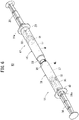
- a syringe kit 10 according to the present embodiment illustrated in Fig. 1 is a mixing kit configured to mix a filling in one barrel and a filling in the other barrel.
- the syringe kit 10 includes a male syringe 12 and a female syringe 14 that can be screw-connected to each other. Both the male syringe 12 and the female syringe 14 are configured as prefilled syringes which are pre-filled with contents such as medicines.
- a side of the male syringe 12 that is connected to the female syringe 14 or a direction thereof is referred to as a "distal end portion” or a “distal end direction”
- the opposite side or the opposite direction is referred to as a "proximal end portion” or a “proximal end direction” in the following description.
- a side of the female syringe 14 that is connected to the male syringe 12 or a direction thereof is referred to as a “distal end portion” or a “distal end direction”
- the opposite side or the opposite direction is referred to as a "proximal end portion” or a "proximal end direction”.
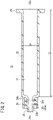
- the male syringe 12 includes: a male syringe barrel 16 formed of a hollow body; a gasket 18 slidably inserted into the male syringe barrel 16; a pusher 20 connected to the gasket 18; and a medicine M filling a barrel chamber 17 formed by the male syringe barrel 16 and the gasket 18.
- the "male syringe barrel 16" is abbreviated as “male barrel 16".
- the male barrel 16 has: a barrel body 22 (male barrel body) having a substantially cylindrical shape and a proximal end opening 22a formed at a proximal end; a nozzle 24 provided at a distal end of the barrel body 22; a lock adapter 26 provided outside the nozzle 24; and a flange 29 formed to protrude radially outward from the proximal end of the barrel body 22;
- the barrel body 22, the nozzle 24, the lock adapter 26, and the flange 29 are integrally formed.
- An outer diameter D1 of the barrel body 22 is not particularly limited, but is preferably 6.7 mm or more.
- an axial length L1 of the barrel body 22 is not particularly limited, but is preferably 35 mm or more, and more preferably 47 mm or more.
- the nozzle 24 extends in the distal end direction while being reduced in diameter from the center of the distal end of the barrel body 22 to the barrel body 22.
- the nozzle 24 has a passage 24b penetrating in the axial direction and communicating with an inner cavity (the barrel chamber 17) of the barrel body 22.
- the nozzle 24 has a circular cross-sectional outer shape and is configured as a male luer having a tapered outer circumferential surface 24a whose outer diameter decreases toward the distal end direction.
- the nozzle 24 can be fitted to a cylindrical portion 38 (female luer), which will be described later, of the female syringe 14.
- the nozzle 24 protrudes in the distal end direction from a distal end surface of the lock adapter 26.
- a cap (not illustrated) is mounted on the nozzle 24 in an initial state of the male syringe 12 illustrated in Fig. 1 , and a distal end opening 24c of the nozzle 24 is sealed by this cap.
- the cap is detached from the nozzle 24 at the time of using the male syringe 12 (at the time of using the syringe kit 10).
- the lock adapter 26 is formed in a substantially hollow cylindrical shape that extends in the distal end direction from the distal end of the barrel body 22 and surrounds the nozzle 24 concentrically.
- An annular recess 26a that is open in the distal end direction is formed between an inner circumferential portion of the lock adapter 26 and an outer circumferential portion of the nozzle 24.
- a screw 28 is formed on an inner circumferential surface of the lock adapter 26. The screw 28 has a screw thread 28a protruding inward from the inner circumferential surface of the lock adapter 26.
- the gasket 18 is inserted into the barrel body 22 via the proximal end opening 22a that is open at the proximal end of the barrel body 22.
- the proximal end side of the barrel body 22 is sealed by the gasket 18 in a liquid-tight manner.
- the gasket 18 is made of an elastic material such as a rubber material.
- the gasket 18 has an outer circumferential portion being in liquid-tight contact with an inner circumferential surface of the barrel body 22 and is arranged to be slidable inside the barrel body 22.
- the gasket 18 is connected to a distal end portion of the pusher 20.
- the pusher 20 When a user presses the pusher 20 in the axial direction (distal end direction or proximal end direction), the gasket 18 slides in the axial direction inside the barrel body 22.
- the pusher 20 may be connected to the gasket 18 at the time of using the male syringe 12.
- the medicine M may be any medicine such as a powdered medicine, a lyophilized medicine, a solid medicine, and a liquid medicine as long as being dissolved, diluted, and mixed by a medical liquid ML (specifically, a dissolving solution such as a physiological saline) filling the inside of the female syringe 14.
- a medical liquid ML specifically, a dissolving solution such as a physiological saline
- examples of the medicine M include protein preparations, peptide preparations, antitumor agents, vitamins (multivitamins), various amino acids, antithrombotic agents such as heparin, insulin, antibiotics, analgesics, cardiotonic agents, intravenous injection anesthetics, medical narcotics, anti-parkinsonian agents, ulcer treatment agents, corticosteroids, arrhythmic agents, and the like.
- the female syringe 14 includes: a female syringe barrel 30 formed of a hollow body; a gasket 32 slidably inserted into the female syringe barrel 30; a pusher 34 connected to the gasket 32; and the medical liquid ML filling a barrel chamber 37 formed by the female syringe barrel 30 and the gasket 32.
- the "female syringe barrel 30" is abbreviated as “female barrel 30".
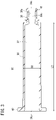
- the female barrel 30 has: a barrel body 36 (female barrel body) having a substantially cylindrical shape and a proximal end opening 36a formed at a proximal end; a cylindrical portion 38 protruding in the distal end direction from a distal end of the barrel body 36; and a flange 40 formed to protrude radially outward from the proximal end of the barrel body 36.
- the barrel body 36, the cylindrical portion 38, and the flange 40 are integrally formed. Note that the cylindrical portion 38 is thinner than the barrel body 36 in Fig. 3 , but the cylindrical portion 38 may have the same thickness as the barrel body 36 or may be thicker than the barrel body 36.
- An outer diameter D2 of the barrel body 36 is not particularly limited, but is preferably 6.7 mm or more.
- an axial length L2 of the barrel body 36 is not particularly limited, but is preferably 35 mm or more, and more preferably 47 mm or more.
- the cylindrical portion 38 extends in the distal end direction while being reduced in diameter from the center of the distal end of the barrel body 36 to the barrel body 36.
- the cylindrical portion 38 has a passage 38b penetrating in the axial direction and communicating with an inner cavity (the barrel chamber 37) of the barrel body 36.
- the cylindrical portion 38 is configured as a female luer having a tapered inner circumferential surface 38a whose outer diameter increases in the distal end direction.
- two protrusions 42 protruding to outer sides (radially outer sides), opposite to each other with respect to an axis (center line) of the cylindrical portion 38, are provided on an outer circumferential portion at the distal end of the cylindrical portion 38.
- the two protrusions 42 have the same shape and size.
- the two protrusions 42 can be screwed with the screw 28 (see Fig. 2 ) provided on the lock adapter 26 of the male barrel 16.
- Each of the protrusions 42 extends in an arc shape in the circumferential direction along an outer circumferential surface of the cylindrical portion 38.
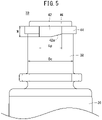
- a length Lp of the protrusion 42 along the radial direction of the cylindrical portion 38 is set to 35 to 65% of an outer diameter Dc of the cylindrical portion 38.
- the length Lp of the protrusion 42 is set to 2.0 to 4.5 mm.
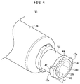
- the length Lp of the protrusion 42 is an external dimension of a protruding end portion of the protrusion 42 in a direction perpendicular to an axis of the cylindrical portion 38 and perpendicular to a direction in which the protrusion 42 protrudes from the cylindrical portion 38 (see also Fig. 4 ) .
- a width W of the protrusion 42 along the axial direction of the cylindrical portion 38 is set to 1.0 to 1.5 mm.
- An inclined surface 42a opposing a trailing flank of the screw 28 (see Fig. 2 ) of the above-described lock adapter 26 is provided at a proximal end portion of the protrusion 42 (an end portion of the protrusion 42 close to the barrel body 36). That is, the inclined surface 42a is inclined with respect to the circumferential direction of the cylindrical portion 38 to be substantially parallel to a spiral extending direction of the screw 28 when the protrusion 42 is screwed with the screw 28.
- a ring-shaped protruding portion 44 that protrudes outward from the distal end portion of the cylindrical portion 38 is integrally provided in the female barrel 30 according to the present embodiment.
- the ring-shaped protruding portion 44 extends in the circumferential direction along the outer circumferential surface of the cylindrical portion 38 with the axis of the cylindrical portion 38 as the center.
- the ring-shaped protruding portion 44 is continuous with the two protrusions 42.
- the two protrusions 42 are integrally provided on an outer circumferential portion of the ring-shaped protruding portion 44.
- the two protrusions 42 protrude outward from the outer circumferential portion of the ring-shaped protruding portion 44.
- each of the protrusions 42 protrudes in the proximal end direction (toward the barrel body 36) from a proximal end surface of the ring-shaped protruding portion 44 (an end surface of the ring-shaped protruding portion 44 close to the barrel body 36).
- a distal end protruding portion 46 that protrudes in the distal end direction from a distal end portion of the cylindrical portion 38, is provided integrally.
- the distal end protruding portion 46 extends in a ring shape in the circumferential direction concentrically with the cylindrical portion 38.
- an outer diameter of the distal end protruding portion 46 is smaller than the outer diameter Dc of the cylindrical portion 38.
- the outer diameter of the distal end protruding portion 46 may be the same as the outer diameter Dc of the cylindrical portion 38, or may be larger than the outer diameter Dc of the cylindrical portion 38.
- the gasket 32 is inserted into the barrel body 36 via the proximal end opening 36a that is open at the proximal end of the barrel body 36.
- the proximal end side of the barrel body 36 is sealed by the gasket 32 in a liquid-tight manner.
- the gasket 32 is made of an elastic material such as a rubber material.
- the gasket 32 has an outer circumferential portion being in liquid-tight contact with an inner circumferential surface of the barrel body 36 and is arranged to be slidable inside the barrel body 36.
- the gasket 32 is connected to a distal end portion of the pusher 34.
- the pusher 34 When a user presses the pusher 34 in the axial direction (distal end direction or proximal end direction), the gasket 32 slides in the axial direction inside the barrel body 36.
- the pusher 34 may be connected to the gasket 32 at the time of using the female syringe 14.
- a cap (not illustrated) is mounted on the cylindrical portion 38, and a distal end opening 38c (see Fig. 3 ) is sealed by this cap.
- the cap is detached from the cylindrical portion 38 at the time of using the female syringe 14 (at the time of using the syringe kit 10).
- the medical liquid ML is a liquid in which the medicine M in the male syringe 12 can be dissolved, diluted, or mixed.
- a medical liquid ML may be a medicine solvent such as a physiological saline, a medicine diluent, a medicine mixture, or a medicinal solution containing a medicine (for example, vitamins and minerals).
- the medical liquid ML is not necessarily poured in the female syringe 14 in advance as in the present embodiment, but may be sucked from a vial or the like into the empty female syringe 14 by the required amount as needed.
- the male barrel 16 and the female barrel 30 are both made of a cyclic polyolefin having high rigidity and high toughness.
- the male barrel 16 and the female barrel 30 may be made of polyesters such as polypropylene, polyethylene, polystyrene, polyamide, polycarbonate, polyvinyl chloride, poly (4-methylpentene-1), an acrylic resin, an acrylonitrile-butadiene-styrene copolymer, and polyethylene terephthalate.
- the caps are detached (opened) from the nozzle 24 of the male barrel 16 and the cylindrical portion 38 of the female barrel 30, respectively, in the male syringe 12 and the female syringe 14 illustrated in Fig. 1 .
- the male barrel 16 and the female barrel 30 are connected to each other as illustrated in Fig. 6 .
- the screw 28 (see Fig. 2 ) of the lock adapter 26 and the protrusion 42 (see Fig. 3 ) provided on the cylindrical portion 38 of the female barrel 30 are screwed.
- the nozzle 24 (male luer) of the male barrel 16 is inserted into the cylindrical portion 38 (female luer) of the female barrel 30.
- the tapered outer circumferential surface 24a (see Fig. 2 ) of the nozzle 24 is liquid-tightly fitted (taper-fitted) to the tapered inner circumferential surface 38a (see Fig. 3 ) of the cylindrical portion 38.
- the medical liquid ML and the medicine M are mixed by performing a pumping operation using the pusher 20 of the male syringe 12 and the pusher 34 of the female syringe 14.
- the pusher 34 of the female syringe 14 is pressed in the distal end direction of the female syringe 14 to inject the medical liquid ML from the female barrel 30 into the male barrel 16, thereby mixing the medical liquid ML and the medicine M in the male barrel 16.
- the pusher 20 of the male syringe 12 is pressed in the distal end direction of the male syringe 12 to inject a mixed liquid (mixture of the medical liquid ML and the medicine M) from the inside of the male barrel 16 into the inside of the female barrel 30.
- the mixed liquid is repeatedly moved between the male barrel 16 and the female barrel 30 several times to promote dissolution, dilution, or mixing of the medicine M, whereby a desired medicinal solution is adjusted.
- the cylindrical portion 38 of the female barrel 30 is provided with the two protrusions 42 that can be screwed to the screw 28 of the lock adapter 26 of the male barrel 16 according to the present embodiment.
- the length Lp of the protrusion 42 along the direction perpendicular to the axis of the cylindrical portion 38 and perpendicular to the direction in which the protrusion 42 protrudes from the cylindrical portion 38 is 2.0 to 4.5 mm
- the width W of the protrusion 42 along the axial direction of the cylindrical portion 38 is 1.0 to 2.1 mm.
- the inclined surface 42a opposing the trailing flank of the screw 28 of the lock adapter 26 is provided at the end portion of the protrusion 42 close to the barrel body 36.
- the protrusion 42 advances over the screw thread 28a of the lock adapter 26 (the protrusion 42 idles) as schematically illustrated in Fig. 7 .
- the protrusion 42 indicated by the virtual line in Fig. 7 is the protrusion 42 before advancing over the screw thread 28a.
- the screw 28 when the screwing between the protrusion 42 and the screw 28 progresses to a certain extent, the fitting between the tapered outer circumferential surface 24a of the nozzle 24 and the tapered inner circumferential surface 38a of the cylindrical portion 38 is completed. Then, when the screw 28 is further screwed from this state, mainly the screw 28 (the lock adapter 26) is elastically deformed outward, so that the protrusion 42 advances over the screw thread 28a.
- the expression that "the protrusion 42 advances over the screw thread 28a" does not mean that the protrusion 42 moves along the spiral shape of the screw 28, but means that the protrusion 42 moves from one side of the screw thread 28a to the other side across the top of the screw thread 28a.
- a male reference connector is specified in ISO594-2 as a connector for testing a locking connector using screw connection.
- the protrusion 42 advances over the screw thread 28a of the lock adapter 26 at the time of screwing the screw 28 and the protrusion 42 by a torque smaller than a torque at which the female syringe 14 is damaged when a convex reference conical fitting for the stress crack test specified in ISO 594-2 is screwed with the female syringe 14. For this reason, it is possible to more reliably prevent the cylindrical portion 38 of the female syringe 14 from being damaged.
- the convex reference conical fitting is made of a material having corrosion resistance (for example, stainless steel).
- the ring-shaped protruding portion 44 (see Fig. 4 ) that protrudes outward from the distal end portion of the cylindrical portion 38 is provided, and the protrusion 42 is formed on the outer circumferential portion of the ring-shaped protruding portion 44.
- the protrusion 42 and the cylindrical portion 38 are reinforced. Therefore, when the protrusion 42 advances over the screw thread 28a of the lock adapter 26, the protrusion 42 and the cylindrical portion 38 are less likely to be deformed, and the liquid tightness between the nozzle 24 and the cylindrical portion 38 is kept favorable.
- the distal end protruding portion 46 (see Fig. 4 ) that protrudes from the distal end portion of the cylindrical portion 38 toward the distal end is provided, and the distal end protruding portion 46 is located to be closer to the distal end than the protrusion 42.
- the protrusion 42 and the cylindrical portion 38 are reinforced. Therefore, when the protrusion 42 advances over the screw thread 28a of the lock adapter 26, the protrusion 42 and the cylindrical portion 38 are less likely to be deformed, and the liquid tightness between the nozzle 24 and the cylindrical portion 38 is kept favorable.
- the female barrel 30 is made of the cyclic polyolefin having high rigidity and toughness in the present embodiment, when the protrusion 42 advances over the screw thread 28a of the lock adapter 26, the protrusion 42 and the cylindrical portion 38 are less likely to be deformed, and the liquid tightness between the nozzle 24 and the cylindrical portion 38 is kept favorable.
- the male barrel 16 is also made of the cyclic polyolefin having high rigidity and toughness in the present embodiment, when the protrusion 42 advances over the screw thread 28a of the lock adapter 26, the nozzle 24 is less likely to be deformed, and the liquid tightness between the nozzle 24 and the cylindrical portion 38 is kept more favorable.
- both the outer diameter D1 of the barrel body 22 of the male barrel 16 and the outer diameter D2 of the barrel body 36 of the female barrel 30 are 6.7 mm or more.
- both the axial length L1 of the barrel body 22 of the male barrel 16 and the axial length L2 of the barrel body 36 of the female barrel 30 are 35 mm or more.
- the protrusion 42 advances over the screw thread 28a even if the barrel bodies 22 and 36 have the above-described external dimensions, and thus, it is possible to prevent the damage and deformation of the cylindrical portion 38 as described above, and the deterioration in liquid tightness between the nozzle 24 and the cylindrical portion 38 can be effectively prevented. Therefore, the present invention is particularly useful when the barrel bodies 22 and 36 have the above-described external dimensions.
- the two protrusions 42 advance over the screw thread 28a of the lock adapter 26 by the predetermined torque at the time of screwing the screw 28 and the two protrusions 42, and the protrusions 42 (and the screw 28) generate the click feeling along with the advancement. For this reason, the user who has performed the screwing operation can easily know that the screwing between the protrusions 42 and the screw 28 has been completed based on the generated click feeling, and it is possible to quickly shift to the next step (the above-described mixing operation). Note that the protrusions 42 (and the screw 28) may generate a click sound together with the click feeling.
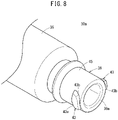
- a female syringe barrel 30a (hereinafter, abbreviated as the "female barrel 30a") according to a first modification illustrated in Figs. 8 and 9 may be adopted, instead of the female barrel 30.
- the female barrel 30a is different from the female barrel 30 illustrated in Fig. 1 and the like in terms that a cylindrical portion 39 is provided instead of the cylindrical portion 38.
- the cylindrical portion 39 has two protrusions 43, which can be screwed with the screw 28 (see Fig. 10 ) provided on the lock adapter 26 of the male syringe 12, on opposite sides on an outer circumferential portion of the cylindrical portion 39.
- a length Lpa of each of the protrusions 43 (the top of each of the protrusions 43) along the radial direction of the cylindrical portion 39 is set to 2.7 to 3.5 mm.
- a width Wa of each of the protrusions 43 (the top of each of the protrusions 43) along the axial direction of the cylindrical portion 39 is set to 1.5 to 2.1 mm.
- the length Lpa of each of the protrusions 43 may be set to 2.0 to 4.5 mm similarly to the length Lp of each of the protrusions 42, and the width Wa of each of the protrusions 43 may be set to 1.0 to 2.1 mm similarly to the width W of each of the protrusions 42.
- each of the two protrusions 43 of the female barrel 30a is provided with an inclined surface 43a opposing the trailing flank of the screw 28 of the lock adapter 26 when the two protrusions 43 are screwed with the screw 28 of the lock adapter 26.
- the inclined surface 43a is configured in the same manner as the inclined surface 42a (see Fig. 5 ) provided on each of the protrusions 42 of the female barrel 30 described above.
- Each of the protrusions 43 has a chamfered corner 43b chamfered on a side surface opposing the inclined surface 42a.
- the chamfered corner 43b is an arcuate curved surface.
- the cylindrical portion 39 includes an abutment portion 45 having an outer diameter Dd of 6.4 to 6.8 mm at a position closer to a proximal end than the two protrusions 43 on the outer circumferential portion of the cylindrical portion 39.
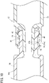
- the abutment portion 45 abuts on an inner circumferential surface 27b of the screw 28 of the lock adapter 26 so as to suppress an inclination of an axis of the cylindrical portion 39 with respect to an axis of the lock adapter 26.
- the outer diameter Dd of the abutment portion 45 is constant along the axial direction of the cylindrical portion 39.
- the abutment portion 45 in the illustrated example is an annular surface (cylindrical surface) that extends over the entire circumference about the axis of the cylindrical portion 39.
- An external shape of the abutment portion 45 in a cross section perpendicular to the axis of the cylindrical portion 39 is not limited to a circle, but may be a non-circular shape such as a polygon.
- the abutment portion 45 may be present partially on the outer circumferential portion in the circumferential direction instead of the entire outer circumferential portion of the cylindrical portion 39.
- the abutment portion 45 is provided continuously from proximal ends 43c of the two protrusions 43 to a position separated by at least 4 mm from a distal end 39a of the cylindrical portion 39 to the barrel body 36.
- a length Lt of the abutment portion 45 along the axial direction of the cylindrical portion 39 is preferably larger than the width Wa of the protrusion 43.
- the female barrel 30a includes the abutment portion 45 having the outer diameter Dd of 6.4 to 6.8 mm at the position closer to the proximal end than the two protrusions 43 on the outer circumferential portion of the cylindrical portion 39. Therefore, the abutment portion 45 abuts on the inner circumferential surface 27b of the screw 28 of the lock adapter 26 when the two protrusions 43 of the cylindrical portion 39 are screwed with the screws 28 of the lock adapter 26 of the male syringe 12 as illustrated in Fig. 10 , so that the inclination of the axis of the cylindrical portion 39 with respect to the axis of the lock adapter 26 is suppressed. For this reason, the cylindrical portion 39 can be prevented from breaking by being screwed with the axis being inclined.
- the cylindrical portion 39 is screwed with the axis of the lock adapter 26 being inclined with respect to the axis of the lock adapter 26, there is a possibility that the cylindrical portion 39 breaks because stress applied to the cylindrical portion 39 becomes uneven in the circumferential direction.
- the abutment portion 45 suppresses the inclination of the axis of the cylindrical portion 39 with respect to the axis of the lock adapter 26 as described above, and thus, it is possible to prevent the breakage of the cylindrical portion 39 due to the uneven stress in the circumferential direction.
- the length Lpa of the protrusion 43 is 2.7 to 3.5 mm
- the width Wa of the protrusion 43 is 1.5 to 2.1 mm
- the protrusion 43 has the chamfered corner 43b chamfered on the side surface opposing the inclined surface 43a. With the above chamfered corner 43b, a corner of the protrusion 43 does not interfere with the screw 28 when the protrusion 43 is formed to be large.
- a female syringe barrel 30A (hereinafter, abbreviated as the "female barrel 30A") according to a second modification illustrated in Fig. 11 may be adopted instead of the female barrel 30.
- This female barrel 30A is obtained by adding a proximal-end-side protruding portion 50 to the female barrel 30 illustrated in Fig. 1 and the like.
- the proximal-end-side protruding portion 50 protrudes from the outer circumferential portion of the cylindrical portion 38 and is provided at a position closer to the proximal end than the protrusion 42 with an interval in the axial direction of the cylindrical portion 38.
- the proximal-end-side protruding portion 50 includes a proximal-end-side ring-shaped protruding portion 52 that protrudes outward from the outer circumferential portion of the cylindrical portion 38 and two proximal-end-side protrusions 54 that protrude to outer sides, opposite to each other, with reference to the axis of the cylindrical portion 38.
- the proximal-end-side ring-shaped protruding portion 52 has the same configuration as the ring-shaped protruding portion 44.
- the two proximal-end-side protrusions 54 are provided on an outer circumferential portion of the proximal-end-side ring-shaped protruding portion 52, and have the same configuration as the two protrusions 42. In the cylindrical portion 38, the two proximal-end-side protrusions 54 are provided at the same circumferential positions as the two protrusions 42.
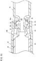
- the proximal-end-side protruding portion 50 protruding from the outer circumferential portion of the cylindrical portion 38 is provided at a position closer to the proximal end than the two protrusions 42 in the female barrel 30A. Therefore, the proximal-end-side protruding portion 50 abuts on an inner circumferential surface 27 of the lock adapter 26 when the two protrusions 42 of the cylindrical portion 38 are screwed with the screw 28 of the lock adapter 26 of the male syringe 12 as illustrated in Figs.12A and 12B , so that the inclination of the axis of the cylindrical portion 38 with respect to the axis of the lock adapter 26 is suppressed. For this reason, the cylindrical portion 38 can be prevented from breaking by being screwed with the axis being inclined.
- the cylindrical portion 38 is screwed with the axis of the lock adapter 26 being inclined with respect to the axis of the lock adapter 26, there is a possibility that the cylindrical portion 38 breaks because stress applied to the cylindrical portion 38 becomes uneven in the circumferential direction.
- the proximal-end-side protruding portion 50 suppresses the inclination of the axis of the cylindrical portion 38 with respect to the axis of the lock adapter 26 as described above, and thus, it is possible to prevent the breakage of the cylindrical portion 38 due to the uneven stress in the circumferential direction.
- the inclination of the axis is prevented as the proximal-end-side protrusion 54 abuts on at least one of an inner circumferential surface 27a between the screw threads 28a of the lock adapter 26 and the inner circumferential surface 27b of the screw thread 28a of the lock adapter 26 during the screwing. That is, during the screwing, the proximal-end-side protrusion 54 opposes the inner circumferential surface 27a between the screw threads 28a of the lock adapter 26 ( Fig. 12A ), and the proximal-end-side ring-shaped protruding portion 52 opposes the inner circumferential surface 27b of the screw thread 28a of the lock adapter 26 ( Fig. 12B ).
- the inclination of the axis is prevented as the proximal-end-side protrusion 54 and the proximal-end-side ring-shaped protruding portion 52 function as abutment portions that abut on the inner circumferential surface 27a between the screw threads 28a of the lock adapter 26 and the inner circumferential surface 27b of the screw thread 28a of the lock adapter 26, respectively, during the screwing.
- the inner circumferential surface 27 of the lock adapter 26 includes the inner circumferential surface 27a between the screw threads 28a and the inner circumferential surface 27b of the screw thread 28a.
- the proximal-end-side protrusion 54 may abut on the inner circumferential surface 27a between the screw threads 28a of the lock adapter 26, and the proximal-end-side ring-shaped protruding portion 52 does not necessarily abut on the inner circumferential surface 27b of the screw thread 28a of the lock adapter 26.
- the proximal-end-side ring-shaped protruding portion 52 may abut on the inner circumferential surface 27b of the screw thread 28a of the lock adapter 26, and the proximal-end-side protrusion 54 does not necessarily abut on the inner circumferential surface 27a between the screw threads 28a of the lock adapter 26.
- proximal-end-side protrusion 54 may be omitted, and the proximal-end-side ring-shaped protruding portion 52 may function as the abutment portion that abuts on the inner circumferential surface 27b of the screw thread 28a of the lock adapter 26 during the screwing.
- the outer diameter of the proximal-end-side ring-shaped protruding portion 52 is preferably 6.4 to 6.8 mm.
- the protrusion 42 advances over the screw thread 28a of the lock adapter 26 as schematically illustrated in Fig. 13 when an excessive torque is applied at the time of screwing the protrusion 42 and the screw 28 of the lock adapter 26.
- the proximal-end-side protrusion 54 also advances over the screw thread 28a similarly to the protrusion 42. For this reason, excessive tightening can be prevented, damage and deformation of the cylindrical portion 38 of the female barrel 30A can be prevented, and deterioration in liquid tightness between the nozzle 24 and the cylindrical portion 38 can be prevented.
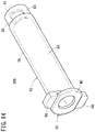
- a female syringe barrel 30B (hereinafter, abbreviated as the "female barrel 30B") according to a third modification illustrated in Fig. 14 may be adopted instead of the female barrel 30.
- the female barrel 30B has a female barrel main body 60 and an outer cylinder 62 that surrounds an outer circumferential portion of the cylindrical portion 38 of the female barrel main body 60 and is not rotatable with respect to the cylindrical portion 38.
- the female barrel main body 60 has the same configuration as the above-described female barrel 30, and thus, its components are denoted by the same reference signs as those of the female barrel 30.
- the outer cylinder 62 illustrated in Fig. 14 is configured to be detachable from the female barrel main body 60.
- the outer cylinder 62 has: a body portion 64 that covers the barrel body 36 of the female barrel main body 60; a distal end cylindrical portion 66 extending in a distal end direction from a distal end of the body portion 64; and a pair of engagement portions 68 protruding to outer sides, opposite to each other, from a proximal end of the body portion 64.
- the outer cylinder 62 is made of a transparent material (for example, the same material as the female barrel main body 60) such that the female barrel main body 60 (and the inside thereof) arranged inside can be visually recognized.
- the distal end cylindrical portion 66 is a hollow cylindrical body surrounding the cylindrical portion 38 of the female barrel main body 60, and is arranged concentrically with the cylindrical portion 38. An annular space is formed between the distal end cylindrical portion 66 and the cylindrical portion 38.
- the distal end cylindrical portion 66 is formed so as to cover the protrusion 42 provided on the cylindrical portion 38. Specifically, in a state where the outer cylinder 62 is mounted on the female barrel main body 60 as illustrated in Fig. 15 , a distal end surface 66a of the distal end cylindrical portion 66 is located to be closer to the distal end than a distal end surface 42b of the protrusion 42 provided on the cylindrical portion 38. Note that the distal end surface 66a of the distal end cylindrical portion 66 may be located at an axial position between the distal end surface 42b and a proximal end surface 42c of the protrusion 42. An inner diameter of the distal end cylindrical portion 66 is slightly larger than an outer diameter of the lock adapter 26 of the male barrel 16.
- the pair of engagement portions 68 is engaged with edges of the flange 40 of the female barrel main body 60 on both sides in the short-axis direction.
- the outer cylinder 62 is not rotatable with respect to the female barrel main body 60.
- a hook that engages with a proximal end surface of the flange 40 may be provided on the engagement portion 68 such that the outer cylinder 62 is not detached from the female barrel main body 60.
- the outer cylinder 62 that surrounds the outer circumferential portion of the cylindrical portion 38 and is not rotatable with respect to the cylindrical portion 38 is provided in the female barrel 30B. Therefore, as illustrated in Fig. 15 , when the two protrusions 42 of the cylindrical portion 38 are screwed with the screw 28 of the lock adapter 26 of the male syringe 12, the lock adapter 26 is inserted between the cylindrical portion 38 and the outer cylinder 62. At this time, an inner circumferential surface of the outer cylinder 62 abuts on the outer circumferential surface of the lock adapter 26, thereby suppressing the inclination of the axis of the cylindrical portion 38 with respect to the axis of the lock adapter 26. For this reason, the cylindrical portion 38 can be prevented from breaking by being screwed with the axis being inclined.
- outer cylinder 62 is not limited to the shape that surrounds most of the female barrel main body 60 as described above, and may be formed integrally with the female barrel main body 60 only around the cylindrical portion 38.
- the fillings may be reversed between the male syringe 12 and the female syringe 14. That is, the male syringe 12 may be filled with the medical liquid ML, and the female syringe 14 may be filled with the medicine M.
Landscapes
- Health & Medical Sciences (AREA)
- Life Sciences & Earth Sciences (AREA)
- Veterinary Medicine (AREA)
- Public Health (AREA)
- General Health & Medical Sciences (AREA)
- Animal Behavior & Ethology (AREA)
- Heart & Thoracic Surgery (AREA)
- Biomedical Technology (AREA)
- Hematology (AREA)
- Anesthesiology (AREA)
- Engineering & Computer Science (AREA)
- Vascular Medicine (AREA)
- Pharmacology & Pharmacy (AREA)
- Physics & Mathematics (AREA)
- Fluid Mechanics (AREA)
- Diabetes (AREA)
- Pulmonology (AREA)
- Infusion, Injection, And Reservoir Apparatuses (AREA)
Claims (6)
- Kit de seringue (10) comprenant :une seringue mâle (12) ayant un cylindre de seringue mâle (16) qui comprend une buse (24) configurée sous la forme d'un raccord Luer mâle, un adaptateur de verrouillage (26) qui entoure une surface circonférentielle externe de la buse (24) et a une vis (28) sur une surface circonférentielle interne et un corps de cylindre mâle (22) raccordé à la buse (24) et à l'adaptateur de verrouillage (26) ; etune seringue femelle (14) ayant un cylindre de seringue femelle (30, 30a, 30A, 30B) qui comprend une partie cylindrique (38, 39) configurée sous la forme d'un raccord Luer femelle sur lequel la buse (24) peut être montée, deux saillies (42, 43) qui font saillie à partir d'une surface circonférentielle externe de la partie cylindrique (38, 39) et peuvent être vissées avec la vis (28) de l'adaptateur de verrouillage (26), et un corps de cylindre femelle (36) raccordé à la partie cylindrique (38, 39),caractérisé en ce que :
chacune des deux saillies (42, 43) a une surface inclinée (42a, 43a), dans lequel :
lorsque la vis (28) et les deux saillies (42, 43) sont vissées, les saillies (42, 43) ayant la surface inclinée (42a, 43a) avancent sur un filetage de vis (28a) de l'adaptateur de verrouillage (26) selon un couple inférieur à un couple auquel la seringue femelle (14) se casse lorsque la seringue femelle (14) est vissée avec un raccord conique de référence convexe pour un test de fissuration sous contrainte spécifié dans la norme ISO 594-2. - Kit de seringue (10) selon la revendication 1, dans lequel :
le cylindre de seringue mâle (16) et le cylindre de seringue femelle (30, 30a, 30A, 30B) sont tous deux réalisés à partir de polyoléfine cyclique. - Kit de seringue (10) selon la revendication 1 ou 2, dans lequel :un diamètre externe (D1) du corps de cylindre mâle (22) et un diamètre externe (D2) du corps de cylindre femelle (36) sont tous deux de 6,7 mm ou plus, etune longueur axiale (L1) du corps de cylindre mâle (22) et une longueur axiale (L2) du corps de cylindre femelle (36) sont toutes deux de 35 mm ou plus.
- Kit de seringue (10) selon l'une quelconque des revendications 1 à 3, dans lequel :un diamètre interne de la vis (28) de l'adaptateur de verrouillage (26) est de 6,8 à 7,2 mm,la partie cylindrique (38, 39) a une partie de butée (45, 52) prévue dans une position plus à proximité d'une extrémité proximale que les deux saillies (42, 43) sur une partie circonférentielle externe de la partie cylindrique (38, 39),la partie de butée (45, 52) a un diamètre externe de 6,4 à 6,8 mm, etla partie de butée (45, 52) vient en butée sur une surface circonférentielle interne de la vis (28) de l'adaptateur de verrouillage (26) afin de supprimer une inclinaison d'un axe de la partie cylindrique (38, 39) par rapport à un axe de l'adaptateur de verrouillage (26) lorsque les deux saillies (42, 43) de la partie cylindrique (38, 39) sont vissées avec la vis (28) de l'adaptateur de verrouillage (26) de la seringue mâle (12).
- Procédé de raccordement de seringue pour raccorder une seringue mâle (12) et une seringue femelle (14) par vissage,la seringue mâle (12) ayant un cylindre de seringue mâle (16) qui comprend une buse (24) configurée sous la forme d'un raccord Luer mâle, et un adaptateur de verrouillage (26) prévu avec une vis (28),une seringue femelle (14) ayant un cylindre de seringue femelle (30, 30a, 30A, 30B) qui comprend une partie cylindrique (38, 39) configurée sous la forme d'un raccord Luer femelle sur lequel la buse (24) peut être montée, et deux saillies (42, 43) pouvant être vissées avec la vis (28) de l'adaptateur de verrouillage (26),caractérisé en ce que :
chacune des deux saillies (42, 43) a une surface inclinée (42a, 43a), le procédé de raccordement de seringue comprenant l'étape consistant à :
amener les saillies (42, 43) ayant la surface inclinée (42a, 43a) à avancer sur un filetage de vis (28a) de l'adaptateur de verrouillage (26) selon un couple prédéterminé lors du vissage de la vis (28) et des deux saillies (42, 43) de sorte qu'une sensation de clic est générée conjointement avec l'avancement. - Procédé de raccordement de seringue selon la revendication 5, dans lequel :la partie cylindrique (38, 39) a une partie de butée (45, 52) prévue dans une position plus à proximité d'une extrémité proximale que les deux saillies (42, 43) sur la partie circonférentielle externe de la partie cylindrique (38, 39), etla partie de butée (45, 52) vient en butée sur une surface circonférentielle interne de l'adaptateur de verrouillage (26) afin de supprimer une inclinaison d'un axe de la partie cylindrique (38, 39) par rapport à un axe de l'adaptateur de verrouillage (26) lorsque la vis (28) et les deux saillies (42, 43) sont vissées.
Applications Claiming Priority (1)
| Application Number | Priority Date | Filing Date | Title |
|---|---|---|---|
| PCT/JP2017/037181 WO2019073593A1 (fr) | 2017-10-13 | 2017-10-13 | Cylindre pour seringue femelle, kit de seringue et procédé de connexion de seringue |
Publications (3)
| Publication Number | Publication Date |
|---|---|
| EP3679914A1 EP3679914A1 (fr) | 2020-07-15 |
| EP3679914A4 EP3679914A4 (fr) | 2020-10-14 |
| EP3679914B1 true EP3679914B1 (fr) | 2022-05-11 |
Family
ID=66100470
Family Applications (1)
| Application Number | Title | Priority Date | Filing Date |
|---|---|---|---|
| EP17928323.9A Active EP3679914B1 (fr) | 2017-10-13 | 2017-10-13 | Cylindre pour seringue femelle, kit de seringue et procédé de connexion de seringue |
Country Status (5)
| Country | Link |
|---|---|
| US (1) | US11998722B2 (fr) |
| EP (1) | EP3679914B1 (fr) |
| KR (1) | KR102522345B1 (fr) |
| CN (1) | CN111194203B (fr) |
| WO (1) | WO2019073593A1 (fr) |
Families Citing this family (2)
| Publication number | Priority date | Publication date | Assignee | Title |
|---|---|---|---|---|
| EP3974010A1 (fr) * | 2020-09-23 | 2022-03-30 | Hubertus Goller Gesellschaft m.b.H. | Seringue multifonctionelle |
| KR102925728B1 (ko) * | 2024-02-06 | 2026-02-11 | (주)다림티센 | 시린지 키트 |
Family Cites Families (16)
| Publication number | Priority date | Publication date | Assignee | Title |
|---|---|---|---|---|
| US5533708A (en) * | 1992-06-04 | 1996-07-09 | Vernay Laboratories, Inc. | Medical coupling site valve body |
| US8226598B2 (en) * | 1999-09-24 | 2012-07-24 | Tolmar Therapeutics, Inc. | Coupling syringe system and methods for obtaining a mixed composition |
| US6610034B1 (en) * | 2000-01-21 | 2003-08-26 | Ultradent Products, Inc. | Thread locking structure |
| US20070068594A1 (en) * | 2005-09-26 | 2007-03-29 | Fischer Dan E | Syringe locking structures |
| JP4895767B2 (ja) * | 2006-11-15 | 2012-03-14 | 株式会社アルテ | 注射器のルアーロック型筒先 |
| US20080140020A1 (en) * | 2006-12-08 | 2008-06-12 | Utah Medical Products Inc. | Lockable enteral feeding adapter |
| US20080140055A1 (en) * | 2006-12-08 | 2008-06-12 | Utah Medical Products, Inc. | Lockable enteral feeding adapter |
| WO2009084646A1 (fr) * | 2007-12-28 | 2009-07-09 | Terumo Kabushiki Kaisha | Joint d'étanchéité pour une seringue et seringue comprenant le joint d'étanchéité |
| US9205248B2 (en) * | 2010-02-24 | 2015-12-08 | Becton, Dickinson And Company | Safety Drug delivery connectors |
| WO2012002315A1 (fr) * | 2010-06-30 | 2012-01-05 | テルモ株式会社 | Connecteur et ensemble connecteur |
| JP5936859B2 (ja) | 2011-12-26 | 2016-06-22 | 株式会社大協精工 | 二薬混合用シリンジキット |
| JP6491096B2 (ja) * | 2013-09-06 | 2019-03-27 | テルモ株式会社 | シリンジ用外筒及びプレフィルドシリンジ |
| EP3050591B1 (fr) * | 2013-09-27 | 2018-09-19 | Terumo Kabushiki Kaisha | Cylindre externe de seringue présentant une fonction de perforation, seringue présentant une fonction de perforation et seringue préremplie présentant une fonction de perforation |
| KR102315224B1 (ko) * | 2013-12-11 | 2021-10-20 | 가부시끼가이샤 제이엠에스 | 수형 커넥터 |
| WO2015151692A1 (fr) * | 2014-03-31 | 2015-10-08 | テルモ株式会社 | Seringue |
| EP3322473B1 (fr) * | 2015-07-15 | 2026-03-25 | Avent, Inc. | Raccords d'adaptation entéraux |
-
2017
- 2017-10-13 CN CN201780095737.8A patent/CN111194203B/zh active Active
- 2017-10-13 KR KR1020207009920A patent/KR102522345B1/ko active Active
- 2017-10-13 WO PCT/JP2017/037181 patent/WO2019073593A1/fr not_active Ceased
- 2017-10-13 EP EP17928323.9A patent/EP3679914B1/fr active Active
-
2020
- 2020-04-13 US US16/846,801 patent/US11998722B2/en active Active
Also Published As
| Publication number | Publication date |
|---|---|
| EP3679914A4 (fr) | 2020-10-14 |
| KR20200071728A (ko) | 2020-06-19 |
| KR102522345B1 (ko) | 2023-04-18 |
| US20200238013A1 (en) | 2020-07-30 |
| CN111194203B (zh) | 2023-04-28 |
| US11998722B2 (en) | 2024-06-04 |
| WO2019073593A1 (fr) | 2019-04-18 |
| EP3679914A1 (fr) | 2020-07-15 |
| CN111194203A (zh) | 2020-05-22 |
Similar Documents
| Publication | Publication Date | Title |
|---|---|---|
| EP1323446B1 (fr) | Récipient du type seringue pour médicament sous forme liquide | |
| US9925343B2 (en) | Luer connection adapters for syringes | |
| JP6880026B2 (ja) | 医療用送達装置 | |
| JP2012085813A (ja) | 二室式容器兼用注射器 | |
| KR20160073386A (ko) | 주입 시스템을 폐쇄하기 위한 팁 캡 조립체 | |
| US9616176B2 (en) | Syringe carpule for storing, transporting and in situ mixing of local anesthetic and buffer, and for delivery of buffered anesthetic solution and a piercing-mixing unit therefore | |
| US20160206821A1 (en) | Syringe barrel with puncture function, syringe with puncture function, and prefilled syringe with puncture function | |
| US11998722B2 (en) | Female syringe barrel, syringe kit, and syringe connection method | |
| GB2495741A (en) | Container for a liquid drug | |
| US20220354747A1 (en) | Syringe set, syringe, and set | |
| JP2011072440A (ja) | 薬剤投与具および薬剤容器装着済み薬剤投与具 | |
| US11311680B2 (en) | Female syringe and syringe kit | |
| JP6782581B2 (ja) | シリンジキット | |
| EP0591156B1 (fr) | Flacon a dosage unitaire | |
| JP4787647B2 (ja) | 医療用容器への薬剤混注器具 | |
| JP5113412B2 (ja) | プレフィルドシリンジ | |
| HK1001552B (en) | Unit dose container | |
| JP2011072395A (ja) | 医療用容器への薬剤混注器具 | |
| JP2004016772A (ja) | プレフィルドシリンジ用注射器およびプレフィルドシリンジ | |
| JP4092987B2 (ja) | プレフィルドシリンジキット | |
| WO2020194565A1 (fr) | Cylindre pour seringue femelle et ensemble seringue femelle | |
| US20250352732A1 (en) | Syringe barrel, syringe, drug preparation set, and method for manufacturing syringe barrel | |
| CN114867521A (zh) | 锁定转接器、注射器组装体及预灌装注射器 |
Legal Events
| Date | Code | Title | Description |
|---|---|---|---|
| STAA | Information on the status of an ep patent application or granted ep patent |
Free format text: STATUS: THE INTERNATIONAL PUBLICATION HAS BEEN MADE |
|
| PUAI | Public reference made under article 153(3) epc to a published international application that has entered the european phase |
Free format text: ORIGINAL CODE: 0009012 |
|
| STAA | Information on the status of an ep patent application or granted ep patent |
Free format text: STATUS: REQUEST FOR EXAMINATION WAS MADE |
|
| 17P | Request for examination filed |
Effective date: 20200409 |
|
| AK | Designated contracting states |
Kind code of ref document: A1 Designated state(s): AL AT BE BG CH CY CZ DE DK EE ES FI FR GB GR HR HU IE IS IT LI LT LU LV MC MK MT NL NO PL PT RO RS SE SI SK SM TR |
|
| AX | Request for extension of the european patent |
Extension state: BA ME |
|
| A4 | Supplementary search report drawn up and despatched |
Effective date: 20200914 |
|
| RIC1 | Information provided on ipc code assigned before grant |
Ipc: A61M 39/00 20060101ALN20200908BHEP Ipc: A61M 5/315 20060101ALN20200908BHEP Ipc: A61M 39/10 20060101ALN20200908BHEP Ipc: A61M 5/178 20060101ALI20200908BHEP Ipc: A61J 1/20 20060101AFI20200908BHEP Ipc: A61M 5/31 20060101ALI20200908BHEP |
|
| DAV | Request for validation of the european patent (deleted) | ||
| DAX | Request for extension of the european patent (deleted) | ||
| GRAP | Despatch of communication of intention to grant a patent |
Free format text: ORIGINAL CODE: EPIDOSNIGR1 |
|
| STAA | Information on the status of an ep patent application or granted ep patent |
Free format text: STATUS: GRANT OF PATENT IS INTENDED |
|
| RIC1 | Information provided on ipc code assigned before grant |
Ipc: A61M 39/10 20060101ALN20220107BHEP Ipc: A61M 39/00 20060101ALN20220107BHEP Ipc: A61M 5/315 20060101ALN20220107BHEP Ipc: A61M 5/31 20060101ALI20220107BHEP Ipc: A61M 5/178 20060101ALI20220107BHEP Ipc: A61J 1/20 20060101AFI20220107BHEP |
|
| RIC1 | Information provided on ipc code assigned before grant |
Ipc: A61M 39/10 20060101ALN20220118BHEP Ipc: A61M 39/00 20060101ALN20220118BHEP Ipc: A61M 5/315 20060101ALN20220118BHEP Ipc: A61M 5/31 20060101ALI20220118BHEP Ipc: A61M 5/178 20060101ALI20220118BHEP Ipc: A61J 1/20 20060101AFI20220118BHEP |
|
| INTG | Intention to grant announced |
Effective date: 20220214 |
|
| GRAS | Grant fee paid |
Free format text: ORIGINAL CODE: EPIDOSNIGR3 |
|
| GRAA | (expected) grant |
Free format text: ORIGINAL CODE: 0009210 |
|
| STAA | Information on the status of an ep patent application or granted ep patent |
Free format text: STATUS: THE PATENT HAS BEEN GRANTED |
|
| AK | Designated contracting states |
Kind code of ref document: B1 Designated state(s): AL AT BE BG CH CY CZ DE DK EE ES FI FR GB GR HR HU IE IS IT LI LT LU LV MC MK MT NL NO PL PT RO RS SE SI SK SM TR |
|
| REG | Reference to a national code |
Ref country code: GB Ref legal event code: FG4D |
|
| REG | Reference to a national code |
Ref country code: CH Ref legal event code: EP |
|
| REG | Reference to a national code |
Ref country code: AT Ref legal event code: REF Ref document number: 1490793 Country of ref document: AT Kind code of ref document: T Effective date: 20220515 |
|
| REG | Reference to a national code |
Ref country code: DE Ref legal event code: R096 Ref document number: 602017057518 Country of ref document: DE |
|
| REG | Reference to a national code |
Ref country code: IE Ref legal event code: FG4D |
|
| REG | Reference to a national code |
Ref country code: LT Ref legal event code: MG9D |
|
| REG | Reference to a national code |
Ref country code: NL Ref legal event code: MP Effective date: 20220511 |
|
| REG | Reference to a national code |
Ref country code: AT Ref legal event code: MK05 Ref document number: 1490793 Country of ref document: AT Kind code of ref document: T Effective date: 20220511 |
|
| PG25 | Lapsed in a contracting state [announced via postgrant information from national office to epo] |
Ref country code: SE Free format text: LAPSE BECAUSE OF FAILURE TO SUBMIT A TRANSLATION OF THE DESCRIPTION OR TO PAY THE FEE WITHIN THE PRESCRIBED TIME-LIMIT Effective date: 20220511 Ref country code: PT Free format text: LAPSE BECAUSE OF FAILURE TO SUBMIT A TRANSLATION OF THE DESCRIPTION OR TO PAY THE FEE WITHIN THE PRESCRIBED TIME-LIMIT Effective date: 20220912 Ref country code: NO Free format text: LAPSE BECAUSE OF FAILURE TO SUBMIT A TRANSLATION OF THE DESCRIPTION OR TO PAY THE FEE WITHIN THE PRESCRIBED TIME-LIMIT Effective date: 20220811 Ref country code: NL Free format text: LAPSE BECAUSE OF FAILURE TO SUBMIT A TRANSLATION OF THE DESCRIPTION OR TO PAY THE FEE WITHIN THE PRESCRIBED TIME-LIMIT Effective date: 20220511 Ref country code: LT Free format text: LAPSE BECAUSE OF FAILURE TO SUBMIT A TRANSLATION OF THE DESCRIPTION OR TO PAY THE FEE WITHIN THE PRESCRIBED TIME-LIMIT Effective date: 20220511 Ref country code: HR Free format text: LAPSE BECAUSE OF FAILURE TO SUBMIT A TRANSLATION OF THE DESCRIPTION OR TO PAY THE FEE WITHIN THE PRESCRIBED TIME-LIMIT Effective date: 20220511 Ref country code: GR Free format text: LAPSE BECAUSE OF FAILURE TO SUBMIT A TRANSLATION OF THE DESCRIPTION OR TO PAY THE FEE WITHIN THE PRESCRIBED TIME-LIMIT Effective date: 20220812 Ref country code: FI Free format text: LAPSE BECAUSE OF FAILURE TO SUBMIT A TRANSLATION OF THE DESCRIPTION OR TO PAY THE FEE WITHIN THE PRESCRIBED TIME-LIMIT Effective date: 20220511 Ref country code: ES Free format text: LAPSE BECAUSE OF FAILURE TO SUBMIT A TRANSLATION OF THE DESCRIPTION OR TO PAY THE FEE WITHIN THE PRESCRIBED TIME-LIMIT Effective date: 20220511 Ref country code: BG Free format text: LAPSE BECAUSE OF FAILURE TO SUBMIT A TRANSLATION OF THE DESCRIPTION OR TO PAY THE FEE WITHIN THE PRESCRIBED TIME-LIMIT Effective date: 20220811 Ref country code: AT Free format text: LAPSE BECAUSE OF FAILURE TO SUBMIT A TRANSLATION OF THE DESCRIPTION OR TO PAY THE FEE WITHIN THE PRESCRIBED TIME-LIMIT Effective date: 20220511 |
|
| PG25 | Lapsed in a contracting state [announced via postgrant information from national office to epo] |
Ref country code: RS Free format text: LAPSE BECAUSE OF FAILURE TO SUBMIT A TRANSLATION OF THE DESCRIPTION OR TO PAY THE FEE WITHIN THE PRESCRIBED TIME-LIMIT Effective date: 20220511 Ref country code: PL Free format text: LAPSE BECAUSE OF FAILURE TO SUBMIT A TRANSLATION OF THE DESCRIPTION OR TO PAY THE FEE WITHIN THE PRESCRIBED TIME-LIMIT Effective date: 20220511 Ref country code: LV Free format text: LAPSE BECAUSE OF FAILURE TO SUBMIT A TRANSLATION OF THE DESCRIPTION OR TO PAY THE FEE WITHIN THE PRESCRIBED TIME-LIMIT Effective date: 20220511 Ref country code: IS Free format text: LAPSE BECAUSE OF FAILURE TO SUBMIT A TRANSLATION OF THE DESCRIPTION OR TO PAY THE FEE WITHIN THE PRESCRIBED TIME-LIMIT Effective date: 20220911 |
|
| PG25 | Lapsed in a contracting state [announced via postgrant information from national office to epo] |
Ref country code: SM Free format text: LAPSE BECAUSE OF FAILURE TO SUBMIT A TRANSLATION OF THE DESCRIPTION OR TO PAY THE FEE WITHIN THE PRESCRIBED TIME-LIMIT Effective date: 20220511 Ref country code: SK Free format text: LAPSE BECAUSE OF FAILURE TO SUBMIT A TRANSLATION OF THE DESCRIPTION OR TO PAY THE FEE WITHIN THE PRESCRIBED TIME-LIMIT Effective date: 20220511 Ref country code: RO Free format text: LAPSE BECAUSE OF FAILURE TO SUBMIT A TRANSLATION OF THE DESCRIPTION OR TO PAY THE FEE WITHIN THE PRESCRIBED TIME-LIMIT Effective date: 20220511 Ref country code: EE Free format text: LAPSE BECAUSE OF FAILURE TO SUBMIT A TRANSLATION OF THE DESCRIPTION OR TO PAY THE FEE WITHIN THE PRESCRIBED TIME-LIMIT Effective date: 20220511 Ref country code: DK Free format text: LAPSE BECAUSE OF FAILURE TO SUBMIT A TRANSLATION OF THE DESCRIPTION OR TO PAY THE FEE WITHIN THE PRESCRIBED TIME-LIMIT Effective date: 20220511 Ref country code: CZ Free format text: LAPSE BECAUSE OF FAILURE TO SUBMIT A TRANSLATION OF THE DESCRIPTION OR TO PAY THE FEE WITHIN THE PRESCRIBED TIME-LIMIT Effective date: 20220511 |
|
| REG | Reference to a national code |
Ref country code: DE Ref legal event code: R097 Ref document number: 602017057518 Country of ref document: DE |
|
| PLBE | No opposition filed within time limit |
Free format text: ORIGINAL CODE: 0009261 |
|
| STAA | Information on the status of an ep patent application or granted ep patent |
Free format text: STATUS: NO OPPOSITION FILED WITHIN TIME LIMIT |
|
| PG25 | Lapsed in a contracting state [announced via postgrant information from national office to epo] |
Ref country code: AL Free format text: LAPSE BECAUSE OF FAILURE TO SUBMIT A TRANSLATION OF THE DESCRIPTION OR TO PAY THE FEE WITHIN THE PRESCRIBED TIME-LIMIT Effective date: 20220511 |
|
| 26N | No opposition filed |
Effective date: 20230214 |
|
| PG25 | Lapsed in a contracting state [announced via postgrant information from national office to epo] |
Ref country code: SI Free format text: LAPSE BECAUSE OF FAILURE TO SUBMIT A TRANSLATION OF THE DESCRIPTION OR TO PAY THE FEE WITHIN THE PRESCRIBED TIME-LIMIT Effective date: 20220511 Ref country code: MC Free format text: LAPSE BECAUSE OF FAILURE TO SUBMIT A TRANSLATION OF THE DESCRIPTION OR TO PAY THE FEE WITHIN THE PRESCRIBED TIME-LIMIT Effective date: 20220511 |
|
| REG | Reference to a national code |
Ref country code: CH Ref legal event code: PL |
|
| REG | Reference to a national code |
Ref country code: BE Ref legal event code: MM Effective date: 20221031 |
|
| PG25 | Lapsed in a contracting state [announced via postgrant information from national office to epo] |
Ref country code: LU Free format text: LAPSE BECAUSE OF NON-PAYMENT OF DUE FEES Effective date: 20221013 |
|
| PG25 | Lapsed in a contracting state [announced via postgrant information from national office to epo] |
Ref country code: LI Free format text: LAPSE BECAUSE OF NON-PAYMENT OF DUE FEES Effective date: 20221031 Ref country code: CH Free format text: LAPSE BECAUSE OF NON-PAYMENT OF DUE FEES Effective date: 20221031 |
|
| PG25 | Lapsed in a contracting state [announced via postgrant information from national office to epo] |
Ref country code: BE Free format text: LAPSE BECAUSE OF NON-PAYMENT OF DUE FEES Effective date: 20221031 |
|
| PG25 | Lapsed in a contracting state [announced via postgrant information from national office to epo] |
Ref country code: IE Free format text: LAPSE BECAUSE OF NON-PAYMENT OF DUE FEES Effective date: 20221013 |
|
| PG25 | Lapsed in a contracting state [announced via postgrant information from national office to epo] |
Ref country code: IT Free format text: LAPSE BECAUSE OF FAILURE TO SUBMIT A TRANSLATION OF THE DESCRIPTION OR TO PAY THE FEE WITHIN THE PRESCRIBED TIME-LIMIT Effective date: 20220511 |
|
| PG25 | Lapsed in a contracting state [announced via postgrant information from national office to epo] |
Ref country code: HU Free format text: LAPSE BECAUSE OF FAILURE TO SUBMIT A TRANSLATION OF THE DESCRIPTION OR TO PAY THE FEE WITHIN THE PRESCRIBED TIME-LIMIT; INVALID AB INITIO Effective date: 20171013 |
|
| PG25 | Lapsed in a contracting state [announced via postgrant information from national office to epo] |
Ref country code: CY Free format text: LAPSE BECAUSE OF FAILURE TO SUBMIT A TRANSLATION OF THE DESCRIPTION OR TO PAY THE FEE WITHIN THE PRESCRIBED TIME-LIMIT Effective date: 20220511 |
|
| PG25 | Lapsed in a contracting state [announced via postgrant information from national office to epo] |
Ref country code: MK Free format text: LAPSE BECAUSE OF FAILURE TO SUBMIT A TRANSLATION OF THE DESCRIPTION OR TO PAY THE FEE WITHIN THE PRESCRIBED TIME-LIMIT Effective date: 20220511 |
|
| PG25 | Lapsed in a contracting state [announced via postgrant information from national office to epo] |
Ref country code: MT Free format text: LAPSE BECAUSE OF FAILURE TO SUBMIT A TRANSLATION OF THE DESCRIPTION OR TO PAY THE FEE WITHIN THE PRESCRIBED TIME-LIMIT Effective date: 20220511 |
|
| PG25 | Lapsed in a contracting state [announced via postgrant information from national office to epo] |
Ref country code: BG Free format text: LAPSE BECAUSE OF FAILURE TO SUBMIT A TRANSLATION OF THE DESCRIPTION OR TO PAY THE FEE WITHIN THE PRESCRIBED TIME-LIMIT Effective date: 20220511 |
|
| PG25 | Lapsed in a contracting state [announced via postgrant information from national office to epo] |
Ref country code: BG Free format text: LAPSE BECAUSE OF FAILURE TO SUBMIT A TRANSLATION OF THE DESCRIPTION OR TO PAY THE FEE WITHIN THE PRESCRIBED TIME-LIMIT Effective date: 20220511 |
|
| PGFP | Annual fee paid to national office [announced via postgrant information from national office to epo] |
Ref country code: GB Payment date: 20250828 Year of fee payment: 9 |
|
| PGFP | Annual fee paid to national office [announced via postgrant information from national office to epo] |
Ref country code: FR Payment date: 20250908 Year of fee payment: 9 |
|
| PG25 | Lapsed in a contracting state [announced via postgrant information from national office to epo] |
Ref country code: TR Free format text: LAPSE BECAUSE OF FAILURE TO SUBMIT A TRANSLATION OF THE DESCRIPTION OR TO PAY THE FEE WITHIN THE PRESCRIBED TIME-LIMIT Effective date: 20220511 |
|
| PGFP | Annual fee paid to national office [announced via postgrant information from national office to epo] |
Ref country code: DE Payment date: 20250902 Year of fee payment: 9 |