EP3679962A1 - Zentrifugalkolben und diese enthaltende zentrifugalvorrichtung - Google Patents
Zentrifugalkolben und diese enthaltende zentrifugalvorrichtung Download PDFInfo
- Publication number
- EP3679962A1 EP3679962A1 EP18855002.4A EP18855002A EP3679962A1 EP 3679962 A1 EP3679962 A1 EP 3679962A1 EP 18855002 A EP18855002 A EP 18855002A EP 3679962 A1 EP3679962 A1 EP 3679962A1
- Authority
- EP
- European Patent Office
- Prior art keywords
- piston
- piston body
- valve
- passage
- materials
- Prior art date
- Legal status (The legal status is an assumption and is not a legal conclusion. Google has not performed a legal analysis and makes no representation as to the accuracy of the status listed.)
- Pending
Links
Images


Classifications
-
- A—HUMAN NECESSITIES
- A61—MEDICAL OR VETERINARY SCIENCE; HYGIENE
- A61M—DEVICES FOR INTRODUCING MEDIA INTO, OR ONTO, THE BODY; DEVICES FOR TRANSDUCING BODY MEDIA OR FOR TAKING MEDIA FROM THE BODY; DEVICES FOR PRODUCING OR ENDING SLEEP OR STUPOR
- A61M1/00—Suction or pumping devices for medical purposes; Devices for carrying-off, for treatment of, or for carrying-over, body-liquids; Drainage systems
- A61M1/02—Blood transfusion apparatus
- A61M1/0272—Apparatus for treatment of blood or blood constituents prior to or for conservation, e.g. freezing, drying or centrifuging
-
- A—HUMAN NECESSITIES
- A61—MEDICAL OR VETERINARY SCIENCE; HYGIENE
- A61M—DEVICES FOR INTRODUCING MEDIA INTO, OR ONTO, THE BODY; DEVICES FOR TRANSDUCING BODY MEDIA OR FOR TAKING MEDIA FROM THE BODY; DEVICES FOR PRODUCING OR ENDING SLEEP OR STUPOR
- A61M1/00—Suction or pumping devices for medical purposes; Devices for carrying-off, for treatment of, or for carrying-over, body-liquids; Drainage systems
- A61M1/02—Blood transfusion apparatus
- A61M1/029—Separating blood components present in distinct layers in a container, not otherwise provided for
-
- A—HUMAN NECESSITIES
- A61—MEDICAL OR VETERINARY SCIENCE; HYGIENE
- A61M—DEVICES FOR INTRODUCING MEDIA INTO, OR ONTO, THE BODY; DEVICES FOR TRANSDUCING BODY MEDIA OR FOR TAKING MEDIA FROM THE BODY; DEVICES FOR PRODUCING OR ENDING SLEEP OR STUPOR
- A61M1/00—Suction or pumping devices for medical purposes; Devices for carrying-off, for treatment of, or for carrying-over, body-liquids; Drainage systems
- A61M1/80—Suction pumps
- A61M1/81—Piston pumps, e.g. syringes
-
- A—HUMAN NECESSITIES
- A61—MEDICAL OR VETERINARY SCIENCE; HYGIENE
- A61M—DEVICES FOR INTRODUCING MEDIA INTO, OR ONTO, THE BODY; DEVICES FOR TRANSDUCING BODY MEDIA OR FOR TAKING MEDIA FROM THE BODY; DEVICES FOR PRODUCING OR ENDING SLEEP OR STUPOR
- A61M1/00—Suction or pumping devices for medical purposes; Devices for carrying-off, for treatment of, or for carrying-over, body-liquids; Drainage systems
- A61M1/88—Draining devices having means for processing the drained fluid, e.g. an absorber
-
- B—PERFORMING OPERATIONS; TRANSPORTING
- B01—PHYSICAL OR CHEMICAL PROCESSES OR APPARATUS IN GENERAL
- B01D—SEPARATION
- B01D21/00—Separation of suspended solid particles from liquids by sedimentation
- B01D21/26—Separation of sediment aided by centrifugal force or centripetal force
- B01D21/262—Separation of sediment aided by centrifugal force or centripetal force by using a centrifuge
-
- B—PERFORMING OPERATIONS; TRANSPORTING
- B01—PHYSICAL OR CHEMICAL PROCESSES OR APPARATUS IN GENERAL
- B01L—CHEMICAL OR PHYSICAL LABORATORY APPARATUS FOR GENERAL USE
- B01L3/00—Containers or dishes for laboratory use, e.g. laboratory glassware; Droppers
- B01L3/50—Containers for the purpose of retaining a material to be analysed, e.g. test tubes
- B01L3/502—Containers for the purpose of retaining a material to be analysed, e.g. test tubes with fluid transport, e.g. in multi-compartment structures
- B01L3/5021—Test tubes specially adapted for centrifugation purposes
- B01L3/50215—Test tubes specially adapted for centrifugation purposes using a float to separate phases
-
- B—PERFORMING OPERATIONS; TRANSPORTING
- B04—CENTRIFUGAL APPARATUS OR MACHINES FOR CARRYING-OUT PHYSICAL OR CHEMICAL PROCESSES
- B04B—CENTRIFUGES
- B04B11/00—Feeding, charging, or discharging bowls
- B04B11/04—Periodical feeding or discharging; Control arrangements therefor
-
- B—PERFORMING OPERATIONS; TRANSPORTING
- B04—CENTRIFUGAL APPARATUS OR MACHINES FOR CARRYING-OUT PHYSICAL OR CHEMICAL PROCESSES
- B04B—CENTRIFUGES
- B04B5/00—Other centrifuges
- B04B5/04—Radial chamber apparatus for separating predominantly liquid mixtures, e.g. butyrometers
- B04B5/0407—Radial chamber apparatus for separating predominantly liquid mixtures, e.g. butyrometers for liquids contained in receptacles
-
- C—CHEMISTRY; METALLURGY
- C12—BIOCHEMISTRY; BEER; SPIRITS; WINE; VINEGAR; MICROBIOLOGY; ENZYMOLOGY; MUTATION OR GENETIC ENGINEERING
- C12M—APPARATUS FOR ENZYMOLOGY OR MICROBIOLOGY; APPARATUS FOR CULTURING MICROORGANISMS FOR PRODUCING BIOMASS, FOR GROWING CELLS OR FOR OBTAINING FERMENTATION OR METABOLIC PRODUCTS, i.e. BIOREACTORS OR FERMENTERS
- C12M45/00—Means for pre-treatment of biological substances
- C12M45/02—Means for pre-treatment of biological substances by mechanical forces; Stirring; Trituration; Comminuting
-
- C—CHEMISTRY; METALLURGY
- C12—BIOCHEMISTRY; BEER; SPIRITS; WINE; VINEGAR; MICROBIOLOGY; ENZYMOLOGY; MUTATION OR GENETIC ENGINEERING
- C12M—APPARATUS FOR ENZYMOLOGY OR MICROBIOLOGY; APPARATUS FOR CULTURING MICROORGANISMS FOR PRODUCING BIOMASS, FOR GROWING CELLS OR FOR OBTAINING FERMENTATION OR METABOLIC PRODUCTS, i.e. BIOREACTORS OR FERMENTERS
- C12M45/00—Means for pre-treatment of biological substances
- C12M45/05—Means for pre-treatment of biological substances by centrifugation
-
- A—HUMAN NECESSITIES
- A61—MEDICAL OR VETERINARY SCIENCE; HYGIENE
- A61M—DEVICES FOR INTRODUCING MEDIA INTO, OR ONTO, THE BODY; DEVICES FOR TRANSDUCING BODY MEDIA OR FOR TAKING MEDIA FROM THE BODY; DEVICES FOR PRODUCING OR ENDING SLEEP OR STUPOR
- A61M2202/00—Special media to be introduced, removed or treated
- A61M2202/08—Lipoids
-
- B—PERFORMING OPERATIONS; TRANSPORTING
- B01—PHYSICAL OR CHEMICAL PROCESSES OR APPARATUS IN GENERAL
- B01L—CHEMICAL OR PHYSICAL LABORATORY APPARATUS FOR GENERAL USE
- B01L2400/00—Moving or stopping fluids
- B01L2400/04—Moving fluids with specific forces or mechanical means
- B01L2400/0403—Moving fluids with specific forces or mechanical means specific forces
- B01L2400/0409—Moving fluids with specific forces or mechanical means specific forces centrifugal forces
-
- B—PERFORMING OPERATIONS; TRANSPORTING
- B01—PHYSICAL OR CHEMICAL PROCESSES OR APPARATUS IN GENERAL
- B01L—CHEMICAL OR PHYSICAL LABORATORY APPARATUS FOR GENERAL USE
- B01L2400/00—Moving or stopping fluids
- B01L2400/04—Moving fluids with specific forces or mechanical means
- B01L2400/0475—Moving fluids with specific forces or mechanical means specific mechanical means and fluid pressure
- B01L2400/0478—Moving fluids with specific forces or mechanical means specific mechanical means and fluid pressure pistons
Definitions
- the following description relates to a piston for centrifugation and a centrifugal separator including the same.
- Adipose tissues obtained from objects, such as people, animals, and the like, by suction or incision contain a mixture of a large amount of oil and impurities, and centrifugation is performed on the adipose tissues to obtain pure fat.
- Korean Patent Application Publication No. 10-2015-0120797 discloses a piston. According to the structure of the piston disclosed in this document, two bodies rotate relative to each other to selectively open or close a flow passage. Accordingly, whether a material passes through the flow passage is determined.
- An aspect provides a piston for centrifugation that interrupts or opens a passage through which a material passes, depending on whether a centrifugal force is applied or not, and a centrifugal separator including the piston.
- a piston for centrifugation that includes a piston body having a passage defined therein and a valve disposed in the passage to selectively open or interrupt the passage, in which the passage extends from the front to the back of the piston, and materials ahead of the piston are movable to the rear of the piston through the passage.
- the materials ahead of the piston are centrifugally separated in a state in which the valve interrupts the passage, and when an external force is applied to the piston while a centrifugal force is not applied to the piston, at least a portion of the materials ahead of the piston are movable to the rear of the piston as the valve opens the passage while freely moving relative to the piston body.
- the center of rotation of the centrifugal force may be located behind the piston body, the piston body may be located inside a container that receives the piston, and the piston body may apply pressure to the materials ahead of the piston while moving along the inside of the container depending on the external force.
- the piston body may include a receiving portion to receive the valve and form a portion of the passage.
- the receiving portion may have an inner surface in a shape corresponding to at least a portion of the valve, and the passage may be interrupted when the valve is contact with the inner surface.
- the passage may include a first path extending from one side of the piston body to the center of the piston body and a second path extending from the center of the piston body to the back of the piston body, and the second path may include a clearance formed between the valve and the inner surface when the valve is separated from the inner surface.
- a portion of the receiving portion having the inner surface may have a decreasing width toward the front of the piston along a lengthwise direction of the piston body.
- a centrifugal separator that includes a piston including a piston body having a passage defined therein, the passage extending from the front to the back of the piston, a valve disposed in the passage, and a sealing member located on the passage and provided between the piston body and the valve, and a push rod to fix the valve to the piston body to interrupt the passage, the push rod being coupled with the piston body and the valve.
- the push rod is contact with the sealing member and interrupts communication of the passage together with the sealing member when the push rod is coupled with the piston body and the valve.
- a portion of the push rod may be disposed inside the piston body to fill a space between the piston body and the valve and may form sealing of the passage together with the sealing member.
- the sealing member may prevent separation of the valve from the piston body before the push rod is coupled with the piston body and the valve, and the sealing member may be elastically deformed before the push rod is separated from the piston body together with the valve after coupled with the piston body and the valve.
- the piston may further include a groove, in which a portion of the sealing member is embedded in the piston body through the groove.
- the valve may include a front valve part having a shape corresponding to an inner surface of the front of the piston body, a rear valve part having a shape corresponding to an inner surface of the back of the piston body, and a protruding component formed between the front valve part and the rear valve part and protruding toward the inner surface of the back of the piston body.
- the distance between the inner surface of the back of the piston body and the protruding component may be smaller than the distance from the inner surface of the back of the piston body to a portion of the sealing member facing toward the rear valve part.
- a centrifugation method for separating bio-materials using a piston for centrifugation includes a piston body having a passage defined therein and a valve disposed in the passage to open or interrupt the passage, in which the passage extends from the front to the back of the piston, and the bio-materials are movable through the passage.
- the bio-materials are located ahead of the piston body, and the center of rotation of a centrifugal force is located behind the piston body.
- the centrifugation method includes separating the bio-materials ahead of the piston body into layers in a direction away from the front of the piston body with respect to the center of rotation in a state in which the valve interrupts the passage while the centrifugal force is applied to the piston, releasing the centrifugal force applied to the piston, connecting a push rod to the piston body, and removing a bio-material farthest away from the piston body among the bio-materials from the container by applying pressure to the bio-materials by pushing the piston body in a direction toward the front of the piston body, moving a bio-material closest to the piston body among the bio-materials to the rear of the piston body through the passage in a state in which the valve opens the passage, by applying pressure to the bio-materials ahead of the piston by pushing the piston with the push rod in a state in which the connection of the push rod to the piston body is released, and obtaining at least one type of remaining bio-materials.
- the piston for centrifugation and the centrifugal separator including the same may obtain a desired material, by interrupting a flow of materials from the front to the back of the piston while a centrifugal force is applied, and allowing a specific material among the materials ahead of the piston to flow to the rear of the piston while a centrifugal force is not applied.
- a component which has the same common function as a component included in any one example embodiment, will be described using the same name in other example embodiments. Unless otherwise stated, the description set forth in any one example embodiment may be applicable to other example embodiments, and a detailed description will be omitted in an overlapping range.
- objects used herein may be used as a concept including living things such as people, animals, and the like.
- biological tissues refers to tissues obtained from the objects.
- the biological tissues may include adipose tissues.
- the biological tissues may be obtained from the objects by a method such as suction or incision.
- the front of a piston refers to an upstream side with respect to a flow stream of a bio-material passing through the piston
- the term “the back of the piston” refers to a downstream side with respect to the flow stream of the bio-material passing through the piston.
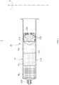
- FIG. 1 is a cross-sectional view schematically illustrating centrifugation performed by a centrifugal separator according to an example embodiment.
- FIG. 2 is a cross-sectional view schematically illustrating removal of a bio-material from a distal region ahead of a piston after the centrifugation is performed by the centrifugal separator according to the example embodiment.
- FIG. 3 is a cross-sectional view schematically illustrating removal of a bio-material from a proximal region ahead of the piston after the centrifugation is performed by the centrifugal separator according to the example embodiment.
- the centrifugal separator 1 is configured to obtain a desired bio-material FL by centrifugally separating bio-materials BL, FL, and OL constituting biological tissue and thereafter removing some bio-materials BL and OL by a predetermined method.
- the centrifugal separator 1 centrifugally separates adipose tissue that is one of biological tissues.
- example embodiments are not necessarily limited thereto.
- the centrifugal separator 1 may include a container 10, a piston 20, and a push rod 30.
- the container 10 is configured to receive adipose tissue, the piston 20, and the push rod 30.
- the container 10 includes a main body 110 having a substantially cylindrical shape.
- the main body 110 may be a syringe.
- the main body 110 has, at the front thereof (at a left end of the main body 110 with respect to FIG. 1 ), an outlet 120 through which a material constituting the adipose tissue escapes from the main body 110.
- the main body 110 has, at the back thereof (at a right end of the main body 110 with respect to FIG. 1 ), an opening through which the adipose tissue, the piston 20, and the push rod 30 are inserted into the main body 110.
- the piston 20 is configured to move in the main body 110.
- the piston 20 may include a piston body 210, a valve 220, and one or more outer sealing members 230.
- the piston body 210 is configured to move in the main body 110.
- a passage extending from the front to the back of the piston 20 is defined in the piston body 210.
- the piston body 210 may have a substantially cylindrical shape.
- the valve 220 is disposed in the passage defined in the piston body 210 and is configured to open or interrupt the passage.
- the valve 220 may selectively open or interrupt the passage as a centrifugal force is applied.
- the valve 220 may be received in the piston body 210 and may freely move in the piston body 210.
- the outer sealing members 230 are coupled to the outside of the piston body 210 and are configured to seal between the piston body 210 and the main body 110.
- the outer sealing members 230 are configured to make contact with an inner surface 112 of the main body 110.
- the piston body 210 may be fixed to the main body 110 in any location of the main body 110 by a frictional force between the outer sealing members 230 and the inner surface 112 of the main body 110.
- the push rod 30 is configured to be coupled with the piston body 210 and the valve 220.
- the push rod 30 may push the piston 20 toward the front of the main body 110 (e.g., by an external force of a user).
- some materials of the adipose tissue ahead of the piston 20 may escape from the main body 110 through the outlet 120.
- the push rod 30 may be separated from the piston body 210.
- the valve 220, together with the push rod 30, may be separated from the piston body 210.
- An axis of rotation X that is the center of rotation for centrifugation may be located behind the main body 110 and behind the piston body 210 (on a right side with respect to FIG. 1 ).
- blood, fluid, pure fat, oil, and the like that constitute the adipose tissue are located ahead of the piston body 210 (on a left side with respect to FIG. 1 ), and the piston 20 is located next.
- the adipose tissue located ahead of the piston 20 is separated into the oil layer OL, the fat layer FL, blood, and the fluid layer BL in sequence from a proximal region to a distal region ahead of the piston 20 according to specific gravity. Meanwhile, the piston body 210 and the valve 220 move in a direction away from the axis of rotation X. In this process, the piston body 210 is fixed to the main body 110 by friction between the outer sealing members 230 coupled to the outside of the piston body 210 and the inner surface 112 of the main body 110, and the valve 220 interrupts the passage defined in the piston body 210 while freely moving in the piston body 210.
- the valve 220 interrupts the passage defined in the piston body 210 during the centrifugation that involves the application of a centrifugal force, the oil layer OL, the fat layer FL, the blood, and the fluid layer BL ahead of the piston 20 cannot move through the passage.
- Some of the materials in the fat layer FL have a very small size and therefore may flow through the passage together with the oil in the oil layer OL in the process in which the centrifugation is performed. Accordingly, in the process in which the centrifugation is performed, the valve 220 may interrupt the passage in the piston body 210, thereby preventing some materials in the fat layer FL, which are materials that a user generally wants, from moving from the front to the back of the piston 20 together with the oil in the oil layer OL.
- the push rod 30 may be coupled to the piston body 210 and the valve 220 in a state in which the centrifugation is completed, with no centrifugal force applied to the piston 20.
- the valve 220 remains interrupting the passage defined in the piston body 210.
- the push rod 30 may be separated from the piston body 210 and the valve 220. Because no centrifugal force is applied to the piston 20, the valve 220 may open the passage defined in the piston body 210 while freely moving in the piston body 210. At this time, the oil in the oil layer OL located in the proximal region ahead of the piston 20 may flow from the front to the back of the piston 20 through the passage defined in the piston body 210. The oil of the oil layer OL that flows to the back of the piston 20 is removed from the container 10, and when the piston 20 is removed from the container 10, the pure fat in the fat layer FL is obtained.
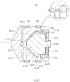
- FIG. 4 is a perspective view schematically illustrating the piston according to an example embodiment
- FIG. 5 is an exploded side view schematically illustrating the piston according to the example embodiment.
- FIG. 6 is a cross-sectional view schematically illustrating a state in which the passage in the piston according to the example embodiment is interrupted
- FIG. 7 is a cross-sectional view schematically illustrating a state in which the passage in the piston according to the example embodiment is open.
- FIG. 8 is a cross-sectional view schematically illustrating a state in which the push rod is coupled to the piston according to the example embodiment.
- the piston 20 may include the piston body 210, the valve 220, the one or more outer sealing members 230, and an inner sealing member 240.
- the piston body 210 may have, on the outside thereof, an inlet 2112 through which a material flows in.
- the oil in the oil layer OL described above with reference to FIG. 3 may enter the piston body 210 through the inlet 2112 and may thereafter flow through the passage defined in the piston body 210.
- the piston body 210 may have, on the outside thereof, one or more recesses 219 in which the one or more outer sealing members 230 are mounted.
- the passage defined in the piston body 210 may have one or more orientations.
- the passage may include a first path 2114 extending from one side of the piston body 210 to the center of the piston body 210, a second path 2116 extending from the center of the piston body 210 to the back of the piston body 210, and a third path 2118 extending from the back of the piston body 210 to the outside of the piston body 210.
- the first path 2114 is configured to be in fluid communication with the inlet 2112
- the second path 2116 is configured to be selectively in fluid communication with the first path 2114 and the third path 2118
- the third path 2118 is configured to be in fluid communication with the outside of the piston body 210.
- the passage defined in the piston body 210 may further include a chamber 2115 located between the first path 2114 and the second path 2116.
- the chamber 2115 may be located in the center of the piston body 210.
- a material may stay in the chamber 2115. While the valve 220 is contact with a first inner surface 2122 of a receiving portion 212, fluid communication between the chamber 2115 and the second path 2116 may be interrupted.
- the piston body 210 may include the receiving portion 212 configured to receive the valve 220.
- the receiving portion 212 may have inner surfaces in shapes corresponding to the external appearance of the valve 220.
- the receiving portion 212 may have the first inner surface 2122 tapered along the fore/aft direction of the piston body 210 and a second inner surface 2124 that meets the first inner surface 2122 and that is substantially horizontal along the fore/aft direction of the piston body 210.
- the first inner surface 2122 may have a gradually increasing width from the front to the back of the piston 20.
- the piston body 210 may include a piston coupling part 214 configured to be coupled with the push rod 30.
- the piston coupling part 214 may include a thread formed on the second inner surface 2124 of the receiving portion 212.
- the valve 220 may include a front valve part 222 and a rear valve part 224.
- the front valve part 222 may be configured to interrupt the passage.
- the front valve part 222 may be contact with an inner surface of at least a portion of the receiving portion 212.
- the front valve part 222 may be contact with the first inner surface 2122 of the receiving portion 212.
- the front valve part 222 may have a shape corresponding to the first inner surface 2122 of the receiving portion 212.
- a clearance may be formed between an outer surface 2222 of the front valve part 222 and the first inner surface 2122 of the receiving portion 212.
- the clearance may be formed when the front valve part 222 is separated from the first inner surface 2122.
- the front valve part 222 makes contact with the first inner surface 2122 of the receiving portion 212 as illustrated in FIG. 6
- no clearance exists between the outer surface 2222 of the front valve part 222 and the first inner surface 2122 of the receiving portion 212
- a clearance is formed between the outer surface 2222 of the front valve part 222 and the first inner surface 2122 of the receiving portion 212.
- the clearance may form at least a portion of the second path 2116.
- the rear valve part 224 is configured to guide a movement of a material along the passage.
- the rear valve part 224 may be parallel to an inner surface of at least a portion of the receiving portion 212.
- the rear valve part 224 may be parallel to the second inner surface 2124 of the receiving portion 212.
- the rear valve part 224 extends from the front valve part 222 toward the back of the piston body 210.
- the valve 220 may include a protruding component 226.
- the protruding component 226 may be formed between the front valve part 222 and the rear valve part 224.
- the protruding component 226 may protrude toward the inner surfaces of the piston body 210.
- the protruding component 226 may protrude toward the second inner surface 2124 of the receiving portion 212.
- the valve 220 may include a valve coupling part 2242.
- the valve coupling part 2242 is configured to be coupled with the push rod 30.
- the valve coupling part 2242 may have a male engagement formation.
- the shape of the valve coupling part 2242 may be appropriately set according to the shape of the push rod 30.
- the valve coupling part 2242 may extend from the rear valve part 224 toward the back of the piston body 210.
- the inner sealing member 240 is configured to prevent separation of the valve 220 from the piston body 210.
- the inner sealing member 240 may be provided between the inner surfaces of the piston body 210 and the valve 220.
- the inner sealing member 240 may be provided on the second inner surface 2124 of the receiving portion 212 on the third path 2128.
- the inner sealing member 240 is configured such that the protruding component 226 is stopped by the inner sealing member 240.
- the inner sealing member 240 may have a ring shape.
- the distance D1 between the second inner surface 2124 of the receiving portion 212 and the protruding component 226 may be smaller than the distance D2 from the second inner surface 2124 of the receiving portion 212 to the inside of the inner sealing member 240.
- a portion of the inner sealing member 240 may be embedded in the piston body 210.
- the receiving portion 212 may include a groove 2126 configured to receive a portion of the inner sealing member 240.
- the groove 2126 may be formed on the second inner surface 2124.
- the inner sealing member 240 prevents the valve 220 from being separated from the piston body 210 when the valve 220 is about to escape from the piston body 210 before the push rod 30 is coupled with the piston body 210 and the valve 220.
- the push rod 30 is coupled with the piston body 210 and the valve 220 and is configured to fix the valve 220 to the piston body 210 to interrupt the passage defined in the piston body 210.
- the push rod 30 may include a first push rod coupling part 342 configured to be coupled with the piston coupling part 214 and a second push rod coupling part 344 located inward of the first push rod coupling part 342 and coupled with the valve coupling part 2242 while facing the rear valve part 224 and surrounding the valve coupling part 2242.
- the first push rod coupling part 342 may have a thread shape.
- the push rod 30 When the push rod 30 is coupled with the piston body 210 and the valve 220, a portion of the push rod 30 may interrupt the passage while making contact with the inner sealing member 240.
- the push rod 30 may include a sealing forming part 346.
- the sealing forming part 346 may make contact with the inner sealing member 240 while filling at least a portion of a space between the piston body 210 and the valve 220. Accordingly, the sealing forming part 346 may interrupt communication of the passage together with the first push rod coupling part 342 and the second push rod coupling part 344.
- the sealing forming part 346 may form sealing of the third path 2118 between the second inner surface 2124 of the receiving portion 212 and the rear valve part 224.
- the contact between the sealing forming part 346 and the inner sealing member 240 is constantly made until the push rod 30 is separated from the piston body 210 together with the valve 220 after the push rod 30 is coupled with the piston body 210 and the valve 220. While the sealing forming part 346 makes contact with the inner sealing member 240, the inner sealing member 240 may be elastically deformed, or may remain deformed.
Landscapes
- Health & Medical Sciences (AREA)
- Life Sciences & Earth Sciences (AREA)
- Chemical & Material Sciences (AREA)
- Engineering & Computer Science (AREA)
- General Health & Medical Sciences (AREA)
- Heart & Thoracic Surgery (AREA)
- Biomedical Technology (AREA)
- Organic Chemistry (AREA)
- Bioinformatics & Cheminformatics (AREA)
- Wood Science & Technology (AREA)
- Zoology (AREA)
- Hematology (AREA)
- Animal Behavior & Ethology (AREA)
- Vascular Medicine (AREA)
- Anesthesiology (AREA)
- Public Health (AREA)
- Veterinary Medicine (AREA)
- Chemical Kinetics & Catalysis (AREA)
- Microbiology (AREA)
- Genetics & Genomics (AREA)
- General Engineering & Computer Science (AREA)
- Biochemistry (AREA)
- Sustainable Development (AREA)
- Biotechnology (AREA)
- Molecular Biology (AREA)
- Clinical Laboratory Science (AREA)
- Analytical Chemistry (AREA)
- Mechanical Engineering (AREA)
- Pathology (AREA)
- Centrifugal Separators (AREA)
Applications Claiming Priority (3)
| Application Number | Priority Date | Filing Date | Title |
|---|---|---|---|
| KR20170113330 | 2017-09-05 | ||
| KR1020180101990A KR102025496B1 (ko) | 2017-09-05 | 2018-08-29 | 원심분리용 피스톤 및 이를 포함하는 원심분리 장치 |
| PCT/KR2018/010273 WO2019050248A1 (ko) | 2017-09-05 | 2018-09-04 | 원심분리용 피스톤 및 이를 포함하는 원심분리 장치 |
Publications (2)
| Publication Number | Publication Date |
|---|---|
| EP3679962A1 true EP3679962A1 (de) | 2020-07-15 |
| EP3679962A4 EP3679962A4 (de) | 2021-05-26 |
Family
ID=65762220
Family Applications (1)
| Application Number | Title | Priority Date | Filing Date |
|---|---|---|---|
| EP18855002.4A Pending EP3679962A4 (de) | 2017-09-05 | 2018-09-04 | Zentrifugalkolben und diese enthaltende zentrifugalvorrichtung |
Country Status (3)
| Country | Link |
|---|---|
| US (1) | US11661578B2 (de) |
| EP (1) | EP3679962A4 (de) |
| KR (1) | KR102025496B1 (de) |
Cited By (2)
| Publication number | Priority date | Publication date | Assignee | Title |
|---|---|---|---|---|
| IT202200025518A1 (it) * | 2022-12-13 | 2024-06-13 | Prometheus Srl | Dispositivo a centrifuga |
| EP4393525A4 (de) * | 2021-08-26 | 2025-10-01 | Bslrest Inc | Kolben zum zentrifugieren und zentrifugationsvorrichtung damit |
Families Citing this family (9)
| Publication number | Priority date | Publication date | Assignee | Title |
|---|---|---|---|---|
| KR102323493B1 (ko) * | 2019-11-11 | 2021-11-09 | 이준석 | 체액 성분 분리 장치 |
| JP7470200B2 (ja) * | 2019-11-11 | 2024-04-17 | ジュン ソク イ | 体液成分分離装置 |
| KR102150716B1 (ko) * | 2019-12-18 | 2020-09-01 | (주)웰포트 | 주사기 일체형 혈소판 추출기구 |
| CN113457220A (zh) * | 2021-07-29 | 2021-10-01 | 厦门博森再生医学工程有限公司 | 一种活塞组件及分离装置 |
| WO2023085708A1 (ko) * | 2021-11-09 | 2023-05-19 | 이준석 | 원심 피스톤 및 이를 포함하는 원심분리 장치 |
| KR102710121B1 (ko) * | 2021-11-09 | 2024-09-27 | 이준석 | 원심 피스톤 및 이를 포함하는 원심분리 장치 |
| US20230390495A1 (en) * | 2022-06-06 | 2023-12-07 | Thome Intellectual Property Holdings, LLC | Nested Molded Piston Parts For Multi-Chamber Syringes |
| US20260000838A1 (en) * | 2022-08-24 | 2026-01-01 | Thorne Intellectual Property Holdings, Llc | Multi-chamber mixing syringe |
| WO2025207088A1 (en) * | 2024-03-27 | 2025-10-02 | Diagnologix, Llc | Closed automated system and method for multiplex cell processing |
Family Cites Families (18)
| Publication number | Priority date | Publication date | Assignee | Title |
|---|---|---|---|---|
| US3931010A (en) | 1974-02-27 | 1976-01-06 | Becton, Dickinson And Company | Serum/plasma separators with centrifugal valves |
| US3887464A (en) | 1974-02-27 | 1975-06-03 | Becton Dickinson Co | Serum/plasma separator with centrifugal valve seal |
| KR100553669B1 (ko) * | 2004-06-23 | 2006-02-24 | 메디칸(주) | 지방 흡입 이식용 주사기의 피스턴 |
| US7927563B1 (en) * | 2009-10-13 | 2011-04-19 | Cytomedix, Inc. | Kit for separation of biological fluids |
| KR101137964B1 (ko) | 2009-12-08 | 2012-04-20 | 도병록 | 지방 조직 이식용 주사기 및 이를 갖는 지방 조직 분배 장치 |
| KR101181187B1 (ko) * | 2011-02-11 | 2012-09-18 | 조희민 | 원심분리용 주사기형 원심관 |
| KR20120131925A (ko) | 2011-05-27 | 2012-12-05 | 이희영 | 주사기용 원심분리장치 및 원심분리방법기 |
| KR20140017230A (ko) | 2012-07-31 | 2014-02-11 | 양경식 | 혈소판 축출 키트 |
| KR20130091514A (ko) | 2012-02-08 | 2013-08-19 | 조희민 | 혈액의 적혈구 분리 수집용구 |
| KR20140004890A (ko) * | 2012-07-03 | 2014-01-14 | 주식회사 무한기업 | 혈액 채취용 주사기 |
| KR101406574B1 (ko) | 2012-08-02 | 2014-06-27 | 조희민 | 혈액의 혈소판 농축 혈장 분리용 수집용구 |
| KR101534243B1 (ko) | 2012-09-24 | 2015-07-06 | 메디칸(주) | 2중형 지방흡입장치 |
| KR200477597Y1 (ko) * | 2013-10-29 | 2015-07-02 | (주)차바이오메드 | 원심분리용 주사기 |
| KR102253045B1 (ko) | 2014-04-18 | 2021-05-18 | 메디칸(주) | 피스톤 |
| KR20160125850A (ko) | 2015-04-22 | 2016-11-01 | 양지훈 | 혈소판추출키트 |
| ES2593042B1 (es) | 2015-06-03 | 2017-10-03 | Biotechnology Institute, I Mas D, S.L. | Dispositivo de recolección de sangre o de un compuesto sanguíneo |
| KR101569175B1 (ko) | 2015-06-30 | 2015-11-13 | 김준우 | 주사기 어댑터 |
| WO2018153884A1 (en) | 2017-02-24 | 2018-08-30 | Asml Netherlands B.V. | Etch bias characterization and method of using the same |
-
2018
- 2018-08-29 KR KR1020180101990A patent/KR102025496B1/ko active Active
- 2018-09-04 EP EP18855002.4A patent/EP3679962A4/de active Pending
- 2018-09-04 US US16/644,502 patent/US11661578B2/en active Active
Cited By (3)
| Publication number | Priority date | Publication date | Assignee | Title |
|---|---|---|---|---|
| EP4393525A4 (de) * | 2021-08-26 | 2025-10-01 | Bslrest Inc | Kolben zum zentrifugieren und zentrifugationsvorrichtung damit |
| IT202200025518A1 (it) * | 2022-12-13 | 2024-06-13 | Prometheus Srl | Dispositivo a centrifuga |
| WO2024127151A1 (en) * | 2022-12-13 | 2024-06-20 | Prometheus S.R.L. | Centrifuge device |
Also Published As
| Publication number | Publication date |
|---|---|
| US11661578B2 (en) | 2023-05-30 |
| EP3679962A4 (de) | 2021-05-26 |
| US20210087518A1 (en) | 2021-03-25 |
| KR20190026585A (ko) | 2019-03-13 |
| KR102025496B1 (ko) | 2019-09-25 |
Similar Documents
| Publication | Publication Date | Title |
|---|---|---|
| US11661578B2 (en) | Centrifugal piston and centrifugal device comprising same | |
| EP3733295B1 (de) | Kolben zur zentrifugation | |
| US5330464A (en) | Reliable breakable closure mechanism | |
| EP2413989B1 (de) | Universalmittel zur trennung von blutbestandteilen | |
| US9289562B2 (en) | Pressure actuated valve for multi-chamber syringe applications | |
| EP2736583B1 (de) | Doppelmembranventil für eine verdrängerpumpe | |
| US9421319B2 (en) | Blood separation container for extracting self-platelet | |
| JP4811404B2 (ja) | 検体採取液容器 | |
| GB1592935A (en) | Device for use in the centrifugal separation of components of a liquid | |
| US20040251217A1 (en) | Apparatus and method for separating and concentrating fluids containing multiple components | |
| CA2988027C (en) | Device for the collecting of blood or a blood compound | |
| KR20150035782A (ko) | 인간 또는 동물 조직의 혈액 또는 다른 물질을 추출, 저장 및/또는 처리하고, 혈액 화합물 또는 다른 생물학적 화합물을 적용하기 위한 장치 | |
| KR20010049172A (ko) | 혈액 채취 방법 및 장치 | |
| KR20190112775A (ko) | 이중 유체 카트리지 조립체 | |
| US20260021225A1 (en) | Body fluid component separating device | |
| KR20160135718A (ko) | 주사기 | |
| JP2022155555A (ja) | 幹細胞を含む体液抽出用バイオキット | |
| EP3912654A1 (de) | Vorrichtung zur trennung von körperflüssigkeitsbestandteilen | |
| JP6721372B2 (ja) | 流路封止部材および血液バッグシステム | |
| US20240286147A1 (en) | Piston for centrifugation and centrifugation device including same | |
| KR101350867B1 (ko) | 비중 구분용 주사기 및 지방 분리 방법 | |
| KR20130088113A (ko) | 비중 구분용 주사기 및 지방 분리 방법 | |
| KR200477597Y1 (ko) | 원심분리용 주사기 | |
| CN114025878A (zh) | 用于封闭用来容纳液体的试样小管的封闭盖 | |
| US20230405610A1 (en) | Centrifugal piston and centrifugal separation device having same |
Legal Events
| Date | Code | Title | Description |
|---|---|---|---|
| STAA | Information on the status of an ep patent application or granted ep patent |
Free format text: STATUS: THE INTERNATIONAL PUBLICATION HAS BEEN MADE |
|
| PUAI | Public reference made under article 153(3) epc to a published international application that has entered the european phase |
Free format text: ORIGINAL CODE: 0009012 |
|
| STAA | Information on the status of an ep patent application or granted ep patent |
Free format text: STATUS: REQUEST FOR EXAMINATION WAS MADE |
|
| 17P | Request for examination filed |
Effective date: 20200331 |
|
| AK | Designated contracting states |
Kind code of ref document: A1 Designated state(s): AL AT BE BG CH CY CZ DE DK EE ES FI FR GB GR HR HU IE IS IT LI LT LU LV MC MK MT NL NO PL PT RO RS SE SI SK SM TR |
|
| AX | Request for extension of the european patent |
Extension state: BA ME |
|
| DAV | Request for validation of the european patent (deleted) | ||
| DAX | Request for extension of the european patent (deleted) | ||
| A4 | Supplementary search report drawn up and despatched |
Effective date: 20210429 |
|
| RIC1 | Information provided on ipc code assigned before grant |
Ipc: A61M 1/02 20060101AFI20210422BHEP Ipc: A61M 1/00 20060101ALI20210422BHEP Ipc: C12M 1/00 20060101ALI20210422BHEP |
|
| STAA | Information on the status of an ep patent application or granted ep patent |
Free format text: STATUS: EXAMINATION IS IN PROGRESS |
|
| 17Q | First examination report despatched |
Effective date: 20260203 |