EP3680004A1 - Reinigungssystem eines fahrzeugs - Google Patents
Reinigungssystem eines fahrzeugs Download PDFInfo
- Publication number
- EP3680004A1 EP3680004A1 EP19217285.6A EP19217285A EP3680004A1 EP 3680004 A1 EP3680004 A1 EP 3680004A1 EP 19217285 A EP19217285 A EP 19217285A EP 3680004 A1 EP3680004 A1 EP 3680004A1
- Authority
- EP
- European Patent Office
- Prior art keywords
- block
- measuring element
- outlet surface
- pollution control
- control system
- Prior art date
- Legal status (The legal status is an assumption and is not a legal conclusion. Google has not performed a legal analysis and makes no representation as to the accuracy of the status listed.)
- Withdrawn
Links
Images

Classifications
-
- F—MECHANICAL ENGINEERING; LIGHTING; HEATING; WEAPONS; BLASTING
- F01—MACHINES OR ENGINES IN GENERAL; ENGINE PLANTS IN GENERAL; STEAM ENGINES
- F01N—GAS-FLOW SILENCERS OR EXHAUST APPARATUS FOR MACHINES OR ENGINES IN GENERAL; GAS-FLOW SILENCERS OR EXHAUST APPARATUS FOR INTERNAL-COMBUSTION ENGINES
- F01N13/00—Exhaust or silencing apparatus characterised by constructional features
- F01N13/008—Mounting or arrangement of exhaust sensors in or on exhaust apparatus
-
- B—PERFORMING OPERATIONS; TRANSPORTING
- B01—PHYSICAL OR CHEMICAL PROCESSES OR APPARATUS IN GENERAL
- B01D—SEPARATION
- B01D53/00—Separation of gases or vapours; Recovering vapours of volatile solvents from gases; Chemical or biological purification of waste gases, e.g. engine exhaust gases, smoke, fumes, flue gases, aerosols
- B01D53/34—Chemical or biological purification of waste gases
- B01D53/92—Chemical or biological purification of waste gases of engine exhaust gases
- B01D53/94—Chemical or biological purification of waste gases of engine exhaust gases by catalytic processes
-
- F—MECHANICAL ENGINEERING; LIGHTING; HEATING; WEAPONS; BLASTING
- F01—MACHINES OR ENGINES IN GENERAL; ENGINE PLANTS IN GENERAL; STEAM ENGINES
- F01N—GAS-FLOW SILENCERS OR EXHAUST APPARATUS FOR MACHINES OR ENGINES IN GENERAL; GAS-FLOW SILENCERS OR EXHAUST APPARATUS FOR INTERNAL-COMBUSTION ENGINES
- F01N3/00—Exhaust or silencing apparatus having means for purifying, rendering innocuous, or otherwise treating exhaust
- F01N3/08—Exhaust or silencing apparatus having means for purifying, rendering innocuous, or otherwise treating exhaust for rendering innocuous
- F01N3/10—Exhaust or silencing apparatus having means for purifying, rendering innocuous, or otherwise treating exhaust for rendering innocuous by thermal or catalytic conversion of noxious components of exhaust
- F01N3/24—Exhaust or silencing apparatus having means for purifying, rendering innocuous, or otherwise treating exhaust for rendering innocuous by thermal or catalytic conversion of noxious components of exhaust characterised by constructional aspects of converting apparatus
- F01N3/28—Construction of catalytic reactors
- F01N3/2803—Construction of catalytic reactors characterised by structure, by material or by manufacturing of catalyst support
- F01N3/2807—Metal other than sintered metal
-
- F—MECHANICAL ENGINEERING; LIGHTING; HEATING; WEAPONS; BLASTING
- F01—MACHINES OR ENGINES IN GENERAL; ENGINE PLANTS IN GENERAL; STEAM ENGINES
- F01N—GAS-FLOW SILENCERS OR EXHAUST APPARATUS FOR MACHINES OR ENGINES IN GENERAL; GAS-FLOW SILENCERS OR EXHAUST APPARATUS FOR INTERNAL-COMBUSTION ENGINES
- F01N3/00—Exhaust or silencing apparatus having means for purifying, rendering innocuous, or otherwise treating exhaust
- F01N3/08—Exhaust or silencing apparatus having means for purifying, rendering innocuous, or otherwise treating exhaust for rendering innocuous
- F01N3/10—Exhaust or silencing apparatus having means for purifying, rendering innocuous, or otherwise treating exhaust for rendering innocuous by thermal or catalytic conversion of noxious components of exhaust
- F01N3/24—Exhaust or silencing apparatus having means for purifying, rendering innocuous, or otherwise treating exhaust for rendering innocuous by thermal or catalytic conversion of noxious components of exhaust characterised by constructional aspects of converting apparatus
- F01N3/28—Construction of catalytic reactors
- F01N3/2803—Construction of catalytic reactors characterised by structure, by material or by manufacturing of catalyst support
- F01N3/2825—Ceramics
- F01N3/2828—Ceramic multi-channel monoliths, e.g. honeycombs
-
- F—MECHANICAL ENGINEERING; LIGHTING; HEATING; WEAPONS; BLASTING
- F01—MACHINES OR ENGINES IN GENERAL; ENGINE PLANTS IN GENERAL; STEAM ENGINES
- F01N—GAS-FLOW SILENCERS OR EXHAUST APPARATUS FOR MACHINES OR ENGINES IN GENERAL; GAS-FLOW SILENCERS OR EXHAUST APPARATUS FOR INTERNAL-COMBUSTION ENGINES
- F01N2330/00—Structure of catalyst support or particle filter
- F01N2330/02—Metallic plates or honeycombs, e.g. superposed or rolled-up corrugated or otherwise deformed sheet metal
-
- F—MECHANICAL ENGINEERING; LIGHTING; HEATING; WEAPONS; BLASTING
- F01—MACHINES OR ENGINES IN GENERAL; ENGINE PLANTS IN GENERAL; STEAM ENGINES
- F01N—GAS-FLOW SILENCERS OR EXHAUST APPARATUS FOR MACHINES OR ENGINES IN GENERAL; GAS-FLOW SILENCERS OR EXHAUST APPARATUS FOR INTERNAL-COMBUSTION ENGINES
- F01N2330/00—Structure of catalyst support or particle filter
- F01N2330/06—Ceramic, e.g. monoliths
-
- F—MECHANICAL ENGINEERING; LIGHTING; HEATING; WEAPONS; BLASTING
- F01—MACHINES OR ENGINES IN GENERAL; ENGINE PLANTS IN GENERAL; STEAM ENGINES
- F01N—GAS-FLOW SILENCERS OR EXHAUST APPARATUS FOR MACHINES OR ENGINES IN GENERAL; GAS-FLOW SILENCERS OR EXHAUST APPARATUS FOR INTERNAL-COMBUSTION ENGINES
- F01N2560/00—Exhaust systems with means for detecting or measuring exhaust gas components or characteristics
-
- Y—GENERAL TAGGING OF NEW TECHNOLOGICAL DEVELOPMENTS; GENERAL TAGGING OF CROSS-SECTIONAL TECHNOLOGIES SPANNING OVER SEVERAL SECTIONS OF THE IPC; TECHNICAL SUBJECTS COVERED BY FORMER USPC CROSS-REFERENCE ART COLLECTIONS [XRACs] AND DIGESTS
- Y02—TECHNOLOGIES OR APPLICATIONS FOR MITIGATION OR ADAPTATION AGAINST CLIMATE CHANGE
- Y02A—TECHNOLOGIES FOR ADAPTATION TO CLIMATE CHANGE
- Y02A50/00—TECHNOLOGIES FOR ADAPTATION TO CLIMATE CHANGE in human health protection, e.g. against extreme weather
- Y02A50/20—Air quality improvement or preservation, e.g. vehicle emission control or emission reduction by using catalytic converters
Definitions
- the invention relates to a vehicle pollution control system.
- the document FR-A1-3036733 discloses a pollution control system comprising a housing in which are housed an oxidation catalyst and a particle filter, these two devices appearing in the form of monoliths.
- the housing is elongated and has a flat extending over the entire length of one of said monoliths. Such a configuration results in the monolith along which the flat part of the housing extends, also having a flat, so that said housing closely matches the shape of the two monoliths.
- the monolith is not bevelled and the case is not designed to accommodate an element for measuring an exhaust gas characterization parameter.
- the document FR-A1-3030619 discloses a depollution device comprising upstream an oxidation catalyst (of the monolith type) and downstream of a particle filter (also of the monolith type).
- the catalyst has a beveled entry end allowing the monolithic block to be drawn back into the exhaust line, so as to release a terminal portion of said line to ensure the evacuation of gases with an increased flow rate.
- the bevel is not on the rear face of the depollution device, and it does not make it possible to accommodate an element for measuring an exhaust gas characterization parameter.
- a system for decontaminating the exhaust gases of a vehicle according to the invention has a monolithic block whose particular geometry allows the presence of an element for measuring a parameter for characterizing the gases leaving said block, said block keeping its depollution capacities intact.
- the subject of the invention is a system for depolluting the exhaust gases from a vehicle engine, comprising a housing, a monolithic cylindrical depollution block having an inlet surface and an outlet surface, and element for measuring a parameter for characterizing the gases leaving the block, the block and the measuring element being housed in the so that said measuring element is located downstream of said block on the side of the outlet surface.
- the outlet surface has at least two flat faces inclined with respect to one another, so as to create in the housing an additional local space between the outlet surface and the measuring element in order to allow said element to be able to function correctly in said case.
- the housing is intended to be inserted into an exhaust line of a vehicle engine, so that the exhaust gases pass through the monolithic pollution control unit by first passing through the inlet surface before exiting at the level of the outlet surface where the measuring element will make it possible to give an indication of the state of the exhaust gases at the outlet of said block.
- the principle of the invention is to reduce the volume of the block compared to a configuration for which said block would have a planar outlet surface and perpendicular to its axis of revolution, so as to locally create a space in the case in order to allow a correct operation of the measuring element. Indeed, it is important that there remains sufficient space between the block and the measurement element so that the measurements made by said element are not biased by the presence too close to the block.
- the term "locally” means that the additional space created in the housing by means of the specific machining of the outlet surface extends over less than a radius of the cylindrical monolithic block.
- the cylindrical monolithic block can for example be a catalyst, or a particle filter or an assembly of these two elements.
- the measuring element can for example be a Nox probe.
- the terms inlet surface, outlet surface and downstream must be interpreted in relation to the direction of propagation of the exhaust gases in the box.
- one of the two inclined faces extends perpendicular to the axis of revolution of the block.
- the additional free space is created along a diameter of the monolithic block, over a length which is less than the radius of said block. In this way the additional free space created at the exit surface of the block is located in a half cross section of the block.
- the outlet surface has a first planar part which is perpendicular to the axis of revolution of the block and which extends beyond the radius of said block, and a second planar part in continuity with said first part and inclined relative thereto.
- the outlet surface of the block is locally bevelled, through the presence of the second planar part inclined relative to the first part.
- the two inclined parts are in continuity with each other, the surface of the first part being greater than the surface of the second part.
- the inclination of the second part takes place in a direction reflecting a removal of material with respect to a configuration for which the second part would be in the same plane as that of the first part.
- the monolithic block was first extended relative to the existing cylindrical blocks, then underwent a removal of local material at its exit surface, in order to create the free space additional allowing the measuring element to operate in good conditions.
- the volume of material removal can remain lower than the volume initially added thanks to the elongation of the block. Indeed, it is important that the monolithic block keeps intact, or even slightly increases if possible, its depollution capacities. Consequently, since the creation of the additional space results in a removal of local material at the level of the block, it is advantageous to lengthen it beforehand so that it retains an almost constant or slightly increased volume.
- the housing is cylindrical and the measuring element is an elongated piece extending radially towards the axis of revolution of said housing.
- the measuring element is to be chosen from an oxygen probe, a nitrogen oxide probe, an ammonia probe and a temperature sensor.
- an oxygen probe a nitrogen oxide probe
- an ammonia probe a temperature sensor.
- the monolithic block is a catalyst.
- Another subject of the invention is a monolithic exhaust gas pollution control block for the production of a pollution control system according to the invention, said block having a cylindrical shape and being provided with an inlet surface and 'an exit surface.
- the outlet surface has at least two flat faces inclined with respect to each other, so as to create in the housing an additional local space between the outlet surface and the measuring element, so as to to allow said element to be able to function correctly in said case.
- the outlet surface has a first planar part which is perpendicular to the axis of revolution of the block and which extends beyond the radius of said block, and a second planar part in continuity with said first part and inclined relative thereto.
- a pollution control system has the advantage of allowing the presence of a measuring element in the housing thanks to simple and judicious machining of the monolithic block. It also has the advantage of keeping its pollution control capabilities intact, or even improving them slightly, despite the presence of the measuring element in the housing.
- a depollution system 1 for the exhaust gases of a vehicle equipped with a heat engine comprises a box 2, a monolithic block 3 for depollution and a measurement element 4 of a parameter for characterizing said gases at the outlet of said block 3.
- the housing 2 is cylindrical in shape and is closed at its two ends, considered along its axis of revolution, by an inlet wall 5 and by an outlet wall 6. Each of these walls 5, 6 has a circular outline and is slightly curved.
- the inlet wall 5 has an opening 7 into which opens an inlet pipe 8 for the exhaust gases, and the outlet wall 6 also has an opening 9 from which an outlet pipe 10 through which the gases are discharged having passed through the monolithic block 3.
- the housing 2 and the two pipes 8, 10 form an integral part of an exhaust line of a vehicle heat engine.
- the monolithic block 3 is a catalyst having a cylindrical shape, having at its two ends considered along its axis of revolution, an inlet surface 11 and an outlet surface 12, said surfaces 11, 12 being planar and having a circular outline.
- This catalyst 3 is a ceramic structure, composed by parallel channels or cells extending parallel to its axis of revolution, and which are separated by walls of any chemical nature, such as, for example, cordierite. In the walls of this structure, an impregnation can be deposited, such as for example alumina containing precious metals.
- the monolithic block 3 is placed in the housing 2 so that their respective axes of revolution are combined.
- the length L of the monolithic block 3 is less than that of the case 2, so that, once said block 3 has been positioned in the case 2 definitively, there remains an upstream space 13 between the entry surface 11 of block 3 and the inlet wall 5 of the housing, and a space downstream 14 between the outlet surface 12 of said block 3 and the outlet wall 6 of said housing 2.
- the measuring element 4 of a parameter for characterizing the gases at the outlet of the monolithic block 3 can be, for example, a temperature sensor, an oxygen sensor capable of measuring an oxygen concentration in the gases having passed through the monolithic block, which is representative of the richness of the gases, a NOx probe capable of measuring a concentration of nitrogen oxides in the gases, etc.
- a temperature sensor capable of measuring an oxygen concentration in the gases having passed through the monolithic block, which is representative of the richness of the gases
- a NOx probe capable of measuring a concentration of nitrogen oxides in the gases, etc.
- Such an element is fixed to the cylindrical wall delimiting the housing 2, so as to open into the downstream space 14 located between the outlet surface 12 of said block 3 and the outlet wall 6 of said housing 2.
- This measuring element 4 is elongated, and extends radially towards the inside of the housing 2, that is to say parallel to the outlet surface 12 of the block 3, leaving a space 16 with said outlet surface 12.
- the measurement of the physical quantities of the gases, in particular of the temperature or of the richness, upstream but also downstream of the monolithic catalyst 3, makes it possible to adapt the strategies for controlling the depollution systems, via for example the engine injection to allow regeneration or purging of pollution control systems 1.
- the arrangement of the catalyst 3 and the probes 4 must therefore be adjusted so that the aerodynamic spraying of the probe 4 ensures good representativeness of the measurement in its "nose" vis-à-vis the homogeneous mixture at the outlet of the monolithic block 3.
- the gases leaving the impregnated monolith 3 have a strong tendency to have a laminar regime and therefore not very representative of the homogeneous mixture when they are measured too close to the channels.
- a minimum distance between the outlet surface 6 of the monolith 3 and the probe 4 is required to maximize the representativeness of the measurements.
- the distance required between the monolithic block 3 and the probe 4 necessary for the proper functioning of the depollution system 1 results in a reduction in the volumes of the implantable monoliths 3.
- the exhaust gases pass through the inlet pipe 8 as indicated by the arrow 15 to arrive in the upstream space 13 before entering the monolithic catalyst 13.
- the gases exit in the downstream space 14 after passing through said catalyst 3, where the element 4 measures a parameter for characterizing the gases.
- the gases are then evacuated from the box 2 through the outlet pipe 10 as indicated by arrow 17.
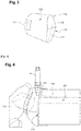
- the catalyst forming the monolithic block 103 has been lengthened compared to the monolithic blocks 3 of the prior art, such as for example that shown in FIG. figure 1 , and has undergone removal of material at the outlet surface 112.
- the catalyst in monolithic form 103 has an inlet surface 111 similar to that of the catalysts 3 of the prior art.
- This catalyst 103 is placed in the housing 2, so that its inlet surface 111 is found in the same position as that of said inlet surface 11 of said existing blocks 3.
- the monolithic block 103 has been lengthened by a length "a" on the side of the outlet surface 112, so that its total length is now L + a.
- this extension was homogeneous over the entire cross section of the monolithic block 103, it is easy to see that the presence of the measuring element 4 would prevent this homogeneous extension, if it is assumed that said measuring element 15 remained in the same place in the case 2.
- said block 103 must be removed in order to creating a space 115 allowing said measuring element 15 to remain at a certain distance from block 103 in order to carry out measurements representative of the real state of the gases at the outlet of block 103.
- this removal of material results in the creation of a bevel at the outlet surface 112.
- said outlet surface 112 has a first planar portion 117 which is perpendicular to the axis of revolution of the block 113 and which extends over more than one radius of said block, and a second planar part 118 in continuity with said first part 117 and inclined with respect thereto.
- the inclination of the second part 118 goes in the direction of a material removal with respect to a configuration for which said second part 118 would be in the same plane as that of the first part 117.
- the first part 117 has an axis of symmetry 116 and extends over a length "b" along said axis of symmetry 117, which is greater than a radius of a cross section of the monolithic block 103. In this way, the surface of the first part 117 is greater than that of the second part 118.
- the measuring element 4 can have the same positioning in the housing 2 without having to undergo the slightest displacement or the slightest structural modification, and maintain high accuracy and reliability in measuring the rate of Nox at the outlet of catalyst 103.
- a pollution control system 100 according to the invention keeps its pollution control power intact compared to existing systems 1, by preserving the volume of the catalyst 103 and the possibility of using a measuring element in good conditions, and the measurements of which will condition the different strategies for injecting fuel into the engine, with a view to obtaining optimized pollution control.
- material removal is an image helping to better understand the new configuration of the outlet surface 112 of the block 103 compared to a configuration for which the monolith block 3 is cylindrical and homogeneous. Indeed, in reality, the block 103 does not undergo any effective material removal, since it is directly manufactured with a bevelled outlet surface 112.
Landscapes
- Chemical & Material Sciences (AREA)
- Engineering & Computer Science (AREA)
- Chemical Kinetics & Catalysis (AREA)
- Combustion & Propulsion (AREA)
- Mechanical Engineering (AREA)
- General Engineering & Computer Science (AREA)
- Health & Medical Sciences (AREA)
- Analytical Chemistry (AREA)
- Toxicology (AREA)
- Ceramic Engineering (AREA)
- Biomedical Technology (AREA)
- Environmental & Geological Engineering (AREA)
- General Chemical & Material Sciences (AREA)
- Oil, Petroleum & Natural Gas (AREA)
- Exhaust Gas After Treatment (AREA)
Applications Claiming Priority (1)
| Application Number | Priority Date | Filing Date | Title |
|---|---|---|---|
| FR1900175A FR3091556A1 (fr) | 2019-01-09 | 2019-01-09 | système de dépollution d’un véhicule |
Publications (1)
| Publication Number | Publication Date |
|---|---|
| EP3680004A1 true EP3680004A1 (de) | 2020-07-15 |
Family
ID=66676808
Family Applications (1)
| Application Number | Title | Priority Date | Filing Date |
|---|---|---|---|
| EP19217285.6A Withdrawn EP3680004A1 (de) | 2019-01-09 | 2019-12-18 | Reinigungssystem eines fahrzeugs |
Country Status (2)
| Country | Link |
|---|---|
| EP (1) | EP3680004A1 (de) |
| FR (1) | FR3091556A1 (de) |
Citations (8)
| Publication number | Priority date | Publication date | Assignee | Title |
|---|---|---|---|---|
| US5857140A (en) * | 1997-10-03 | 1999-01-05 | General Motors Corporation | Catalytic converter |
| EP1158145A2 (de) * | 2000-05-20 | 2001-11-28 | Bayerische Motoren Werke Aktiengesellschaft | Vorrichtung zur Steuerung/Regelung der Regeneration eines NOX-Speicherkatalysators im Abgasstrang einer Brennkraftmaschine |
| AT6726U1 (de) * | 2002-12-19 | 2004-03-25 | Roitner Johann Dipl Ing | Formkörper sowie verwendung eines formkörpers |
| US20080170972A1 (en) * | 2007-01-11 | 2008-07-17 | Haimian Cai | Catalytic converter with sensor cavity |
| DE102007042821A1 (de) * | 2007-07-26 | 2009-01-29 | Volkswagen Ag | Abgasreinigungsvorrichtung |
| EP2332634A1 (de) * | 2009-12-14 | 2011-06-15 | NGK Insulators, Ltd. | Wabenförmiger Katalysatorkörper mit Sensorvorrichtung |
| FR3030619A1 (fr) | 2014-12-18 | 2016-06-24 | Renault Sa | Groupe motopropulseur d'un vehicule dote d'un systeme de depollution ameliore |
| FR3036733A1 (fr) | 2015-05-28 | 2016-12-02 | Renault Sa | Systeme de depollution compact d'un vehicule |
-
2019
- 2019-01-09 FR FR1900175A patent/FR3091556A1/fr active Pending
- 2019-12-18 EP EP19217285.6A patent/EP3680004A1/de not_active Withdrawn
Patent Citations (8)
| Publication number | Priority date | Publication date | Assignee | Title |
|---|---|---|---|---|
| US5857140A (en) * | 1997-10-03 | 1999-01-05 | General Motors Corporation | Catalytic converter |
| EP1158145A2 (de) * | 2000-05-20 | 2001-11-28 | Bayerische Motoren Werke Aktiengesellschaft | Vorrichtung zur Steuerung/Regelung der Regeneration eines NOX-Speicherkatalysators im Abgasstrang einer Brennkraftmaschine |
| AT6726U1 (de) * | 2002-12-19 | 2004-03-25 | Roitner Johann Dipl Ing | Formkörper sowie verwendung eines formkörpers |
| US20080170972A1 (en) * | 2007-01-11 | 2008-07-17 | Haimian Cai | Catalytic converter with sensor cavity |
| DE102007042821A1 (de) * | 2007-07-26 | 2009-01-29 | Volkswagen Ag | Abgasreinigungsvorrichtung |
| EP2332634A1 (de) * | 2009-12-14 | 2011-06-15 | NGK Insulators, Ltd. | Wabenförmiger Katalysatorkörper mit Sensorvorrichtung |
| FR3030619A1 (fr) | 2014-12-18 | 2016-06-24 | Renault Sa | Groupe motopropulseur d'un vehicule dote d'un systeme de depollution ameliore |
| FR3036733A1 (fr) | 2015-05-28 | 2016-12-02 | Renault Sa | Systeme de depollution compact d'un vehicule |
Also Published As
| Publication number | Publication date |
|---|---|
| FR3091556A1 (fr) | 2020-07-10 |
Similar Documents
| Publication | Publication Date | Title |
|---|---|---|
| EP1588032B1 (de) | Verfahren zur nacheinspritzung von zur regenerierung geeigneten kohlenwasserstoffen, alkohole und/oder reduktionsmittel (z.b. diesel-kraftstoff und/oder harnstoff und/oder ammoniakalische lösung) zur regeneration von abgasfiltersystemen in dieselmotoren | |
| EP2522822B1 (de) | System mit einem Verbrennungsmotor, einer U-Einheit zur Abgasnachbehandlung und einem optimisierten Hitzeschild | |
| EP1920815A2 (de) | Behandlungsverfahren für unverbranntes Methan durch Plasmaoxidation | |
| FR3021353A1 (fr) | Procede et dispositif de diagnostic du demontage d'un composant d'une installation de nettoyage des gaz d'echappement | |
| EP3884268A1 (de) | Sonde zur messung der zusammensetzung eines oxidierenden gases | |
| EP1410000A1 (de) | Einrichtung zur laserinduzierten fluoreszenzanalyse und trennvorrichtung damit | |
| EP4698884A1 (de) | System zur entnahme von gas aus einem festen porösen medium | |
| WO1999047896A1 (fr) | Compteur de gaz a filtres anti-poussieres | |
| CH702326B1 (fr) | Procédé d'étalonnage d'un système de mesure et de surveillance d'émissions polluantes utilisant un laser dans le spectre infrarouge moyen. | |
| FR3091556A1 (fr) | système de dépollution d’un véhicule | |
| EP2076659B1 (de) | Abgasleitung mit einem Kraftstoffeinspritzventil und Mitteln zur Homogenisierung von verbrannten Gasen | |
| FR2721974A1 (fr) | Detecteur d'echappement et procede de detection | |
| EP2126299A1 (de) | Abgasstrecke für verbrennungsmotor mit vorrichtung zur reduktion von stickstoffoxiden | |
| FR2939890A3 (fr) | Dispositif d'echantillonnage d'un gaz ou d'un aerosol, notamment d'un gaz de combustion automobile | |
| CA2458983C (fr) | Procede de regeneration d'un dispositif de filtration des gaz d'echappement pour moteur diesel et dispositif de mise en oeuvre | |
| FR2631441A1 (fr) | Debitmetre a double vortex bloque | |
| EP3062011A1 (de) | Messsystem eines ammoniak-speichersystems basierend auf der messung der brechungsindexänderung | |
| FR2938006A3 (fr) | Dispositif de depollution des gaz d'echappement equipe d'une structure cylindrique poreuse comportant une face amont oblique. | |
| EP1914400B1 (de) | Abgasanlage mit einem Katalysator und einer Temperatursonde | |
| FR3006708A1 (fr) | Ensemble de post-traitement des gaz d'echappement d'un moteur thermique | |
| EP3098410B1 (de) | Kompaktes abgasreinugungssystem eines fahrzeugs | |
| FR2701514A1 (fr) | Procédé d'épuration par micro-ondes des gaz d'échappement de moteurs à combustion interne et dispositif de mise en Óoeuvre. | |
| WO2006087454A1 (fr) | Dispositif de depollution des gaz d'echappement d'un moteur thermique | |
| FR3044419A1 (fr) | Detecteur de gaz et son procede de fabrication | |
| FR2948410A3 (fr) | Dispositif de regeneration d'un filtre a particules pour un banc d'essai d'un moteur a combustion interne et banc moteur comportant un tel dispositif |
Legal Events
| Date | Code | Title | Description |
|---|---|---|---|
| PUAI | Public reference made under article 153(3) epc to a published international application that has entered the european phase |
Free format text: ORIGINAL CODE: 0009012 |
|
| STAA | Information on the status of an ep patent application or granted ep patent |
Free format text: STATUS: THE APPLICATION HAS BEEN PUBLISHED |
|
| AK | Designated contracting states |
Kind code of ref document: A1 Designated state(s): AL AT BE BG CH CY CZ DE DK EE ES FI FR GB GR HR HU IE IS IT LI LT LU LV MC MK MT NL NO PL PT RO RS SE SI SK SM TR |
|
| AX | Request for extension of the european patent |
Extension state: BA ME |
|
| STAA | Information on the status of an ep patent application or granted ep patent |
Free format text: STATUS: REQUEST FOR EXAMINATION WAS MADE |
|
| 17P | Request for examination filed |
Effective date: 20201228 |
|
| RBV | Designated contracting states (corrected) |
Designated state(s): AL AT BE BG CH CY CZ DE DK EE ES FI FR GB GR HR HU IE IS IT LI LT LU LV MC MK MT NL NO PL PT RO RS SE SI SK SM TR |
|
| STAA | Information on the status of an ep patent application or granted ep patent |
Free format text: STATUS: EXAMINATION IS IN PROGRESS |
|
| 17Q | First examination report despatched |
Effective date: 20210430 |
|
| STAA | Information on the status of an ep patent application or granted ep patent |
Free format text: STATUS: THE APPLICATION IS DEEMED TO BE WITHDRAWN |
|
| RAP3 | Party data changed (applicant data changed or rights of an application transferred) |
Owner name: RENAULT S.A.S |
|
| 18D | Application deemed to be withdrawn |
Effective date: 20210911 |