EP3680130A1 - Accoudoir - Google Patents
Accoudoir Download PDFInfo
- Publication number
- EP3680130A1 EP3680130A1 EP20150691.2A EP20150691A EP3680130A1 EP 3680130 A1 EP3680130 A1 EP 3680130A1 EP 20150691 A EP20150691 A EP 20150691A EP 3680130 A1 EP3680130 A1 EP 3680130A1
- Authority
- EP
- European Patent Office
- Prior art keywords
- armrest
- guide
- guide means
- drive part
- spring
- Prior art date
- Legal status (The legal status is an assumption and is not a legal conclusion. Google has not performed a legal analysis and makes no representation as to the accuracy of the status listed.)
- Granted
Links
Images



Classifications
-
- A—HUMAN NECESSITIES
- A47—FURNITURE; DOMESTIC ARTICLES OR APPLIANCES; COFFEE MILLS; SPICE MILLS; SUCTION CLEANERS IN GENERAL
- A47C—CHAIRS; SOFAS; BEDS
- A47C7/00—Parts, details, or accessories of chairs or stools
- A47C7/54—Supports for the arms
- A47C7/543—Supports for the arms movable to inoperative position
-
- B—PERFORMING OPERATIONS; TRANSPORTING
- B60—VEHICLES IN GENERAL
- B60N—SEATS SPECIALLY ADAPTED FOR VEHICLES; VEHICLE PASSENGER ACCOMMODATION NOT OTHERWISE PROVIDED FOR
- B60N2/00—Seats specially adapted for vehicles; Arrangement or mounting of seats in vehicles
- B60N2/75—Arm-rests
- B60N2/753—Arm-rests movable to an inoperative position
-
- B—PERFORMING OPERATIONS; TRANSPORTING
- B60—VEHICLES IN GENERAL
- B60N—SEATS SPECIALLY ADAPTED FOR VEHICLES; VEHICLE PASSENGER ACCOMMODATION NOT OTHERWISE PROVIDED FOR
- B60N2/00—Seats specially adapted for vehicles; Arrangement or mounting of seats in vehicles
- B60N2/02—Seats specially adapted for vehicles; Arrangement or mounting of seats in vehicles the seat or part thereof being movable, e.g. adjustable
- B60N2/0224—Non-manual adjustments, e.g. with electrical operation
- B60N2/02246—Electric motors therefor
- B60N2/02253—Electric motors therefor characterised by the transmission between the electric motor and the seat or seat parts
-
- B—PERFORMING OPERATIONS; TRANSPORTING
- B60—VEHICLES IN GENERAL
- B60N—SEATS SPECIALLY ADAPTED FOR VEHICLES; VEHICLE PASSENGER ACCOMMODATION NOT OTHERWISE PROVIDED FOR
- B60N2/00—Seats specially adapted for vehicles; Arrangement or mounting of seats in vehicles
- B60N2/75—Arm-rests
- B60N2/753—Arm-rests movable to an inoperative position
- B60N2/757—Arm-rests movable to an inoperative position in a recess of the back-rest
-
- B—PERFORMING OPERATIONS; TRANSPORTING
- B60—VEHICLES IN GENERAL
- B60N—SEATS SPECIALLY ADAPTED FOR VEHICLES; VEHICLE PASSENGER ACCOMMODATION NOT OTHERWISE PROVIDED FOR
- B60N2/00—Seats specially adapted for vehicles; Arrangement or mounting of seats in vehicles
- B60N2/75—Arm-rests
- B60N2/763—Arm-rests adjustable
- B60N2/777—Transversal adjustment
-
- B—PERFORMING OPERATIONS; TRANSPORTING
- B60—VEHICLES IN GENERAL
- B60N—SEATS SPECIALLY ADAPTED FOR VEHICLES; VEHICLE PASSENGER ACCOMMODATION NOT OTHERWISE PROVIDED FOR
- B60N2/00—Seats specially adapted for vehicles; Arrangement or mounting of seats in vehicles
- B60N2/02—Seats specially adapted for vehicles; Arrangement or mounting of seats in vehicles the seat or part thereof being movable, e.g. adjustable
- B60N2002/0204—Seats specially adapted for vehicles; Arrangement or mounting of seats in vehicles the seat or part thereof being movable, e.g. adjustable characterised by the seat or seat part turning about or moving along a non-standard, particular axis, i.e. an axis different from the axis characterising the conventional movement
- B60N2002/0216—Seats specially adapted for vehicles; Arrangement or mounting of seats in vehicles the seat or part thereof being movable, e.g. adjustable characterised by the seat or seat part turning about or moving along a non-standard, particular axis, i.e. an axis different from the axis characterising the conventional movement the seat or seat part turning about or moving along a transversal axis
Definitions
- the invention relates to an armrest for a seat, in particular for a vehicle seat.
- Such an armrest comprises a base part and an armrest pivotably mounted on the base part.
- the armrest is movable relative to the base about the pivot axis between a non-use and a use position.
- an armrest with a guide device which comprises two coaxial sleeves, one sleeve being held on the seat structure and a second sleeve on the armrest.
- a link is formed in the first sleeve, in which a pin firmly connected to the second sleeve engages.
- the backdrop runs helically in the circumferential direction and in the longitudinal direction of the first sleeve. In this way, in addition to the pivoting movement, the armrest is also moved in the longitudinal direction of the pivoting axis when moving from the non-use to the use position.
- the armrest according to DE 10 2007 014 232 B4 can be displaced relative to a base in the longitudinal direction of a pivot axis and can be pivoted about an approximately vertical and a horizontal position about the pivot axis. In this way, the armrest can be stowed in a recess in the seat in the non-use position and does not take up any space to the side of the seat.
- the armrest according to FR 2 885 329 includes a base, an armrest and an intermediate element.
- the intermediate element forms with the base a first swivel joint with a vertical swivel axis.
- the armrest forms with the intermediate element a second swivel joint with a horizontal swivel axis.
- the armrest according to the invention comprises a base and an armrest which can be moved between at least one use position and a non-use position by means of a guide device.
- the basis is e.g. formed by a vehicle structure or the structure of a seat.
- the base can e.g. also be formed by a part which is firmly connected to a seat.
- the guide device guides the armrest during the movement between the non-use position and the at least one use position.
- the armrest executes both a movement parallel to the longitudinal direction of the pivot axis and a rotational movement about the pivot axis.
- the armrest is, for example, by means of an axial guide between one relative to the base proximal and a distal position movable in a first direction and pivotable between a primary and a secondary position by means of a rotation guide.
- the movement parallel to the longitudinal direction of the pivot axis and the rotational movement about the pivot axis can be carried out in succession or at the same time.
- the guide is formed, for example, by a guide in which a guide block is guided.
- the armrest comprises a drive device with a motor drive.
- the motor drive is provided with a drive part which is movable in a first direction between a first and a second position in order to at least partially shift the armrest between the non-use position and the use position.
- the drive member merely axially displaces the armrest between the proximal and distal positions.
- first direction and second direction are not only to be understood in the sense of the invention as mere spatial directions, they can also be understood as an orientation on a movement path, which e.g. going in opposite directions.
- the motor drive is e.g. formed by a linear drive. Alternatively, other drives can also be involved.
- the linear drive is e.g. formed by a spindle which cooperates with a spindle nut, the spindle or the spindle nut being driven by a motor in order to move the drive part between the first and the second position.
- the drive device comprises, for example, a spring which can be tensioned between the first position and the second position when the drive part or a separate second drive part is moved.
- the armrest With the spring, the armrest can be moved axially in a second direction, which is opposite to the first direction.
- the drive device has, for example, a separate motor for driving the drive part.
- the spring can be tensioned, for example, when the drive part moves from the first position to the second position. Alternatively, the spring can be tensioned when the drive part moves from the second position to the first position.
- the invention has the advantage, among other things, that due to the partial movement of the armrest by means of a spring, the risk of getting caught can be avoided without the need for complex sensors or overload protection devices. If e.g. the critical movement of the armrest from the use position into the non-use position - in which there is a risk of limbs of a seat occupant jamming between the armrest and the seat - by spring force, injuries are avoided.
- An embodiment is characterized in that the base is provided with first guide means which cooperate with second guide means which are assigned to the armrest.
- the first guide means and the second guide means form e.g. an axial guide and / or a rotary guide for the armrest.
- the armrest is e.g. when moving between the proximal and distal positions and / or when moving between the primary position and the secondary position.
- the first guide means and / or the second guide means are formed, for example, by a tube and the guide means can be moved telescopically with respect to one another.
- This embodiment is space-saving since the first and the second guide means are nested in the non-use position and only slightly overlapped in the use position. If the first and the second guide means are formed by a tube, is also in the interior The inner tube has space for other armrest components.
- One embodiment is characterized in that when the drive part moves between the first position and the second position, the second guide means can be displaced relative to the first guide means between the proximal position and the distal position.
- the second guide means are e.g. linearly displaceable between the proximal position and the distal position.
- the second guide means are thus shifted from the drive part from the proximal position to the distal position by means of the motor drive or are shifted from the distal position to the proximal position.
- the second guide means can e.g. locked in such a way that a return movement is only possible in a certain position of the armrest.
- the second guide means have a stop surface which cooperates with a driving surface of the drive part in such a way that the second guide means are carried along when the drive part moves in a first direction and when moved in a second direction are detachable from each other. Since the drive part is only loosely connected to the second guide means, it is possible for the second guide means to be carried along only during one of the movements from the first position to the second position of the drive part or from the second position to the first position of the drive part the opposite movement has the opportunity to detach itself from the second guide means.
- An embodiment is characterized in that a tie rod is fixedly connected to the drive part or to a separate drive part of the drive device and that a first Spring end of a spring is supported on the tie rod.
- the drive part can move the tie rod in such a way that the spring is tensioned and loads the second guide means into the proximal position or into the distal position.
- the same drive part that moves the second positive locking means or a separate drive part of the drive device, which is provided with a separate drive can be used for the movement of the tie rod.
- a second spring end is supported on a contact surface of the second guide means.
- a first spring end is supported, for example, on a contact surface of the tie rod.
- the second guide means can be moved from the proximal position to the distal position.
- the second guide means can be moved from the distal position to the proximal position.
- the spring can be tensioned by the tie rod.
- the tie rod is moved by the drive part during the return movement from the first position to the second position in such a way that the spring is tensioned.
- the armrest can be moved about 20 ° before reaching the secondary position in contact with a separate spring which brakes the armrest at this pivoting angle, the spring being tensioned.
- An embodiment is characterized in that a damping device for damping the pivoting movement of the armrest from the non-use position to the use position is provided. In this way the armrest is pivoted into the use position.
- the pivoting movement of the armrest is supported by a spring.
- the movement of the armrest can be spring-loaded from an approximately vertical position to an approximately horizontal position.
- the movement of the armrest from the horizontal position to the vertical position can be spring-loaded.
- the armrest as a whole is designated by the reference number 10 in the figures.
- the same reference numerals in the different figures designate corresponding parts, even if small letters have been added or omitted.
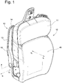
- the armrest 10 is attached to the backrest 11 of a vehicle seat 12.
- a contact surface 49 of the backrest 11 is aligned in the direction x1.
- the direction x1 corresponds, for example, to the straight-ahead direction of travel of the vehicle, while a back surface 15 of the backrest is directed in the opposite direction x2.
- the seat surface of the vehicle seat is not shown.
- the armrest 10 is in a non-use position, an armrest 13 with a lower surface 14 at least partially a rear surface 15 (in Fig. 1 not recognizable) opposite the backrest 11.
- the armrest protrudes laterally in the non-use position only slightly or not at all beyond a side surface 16 of the backrest 11.
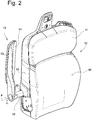
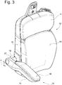
- the armrest 13 can be moved parallel to the longitudinal direction of a pivot axis a in the directions y 1 and y 2 and around the Swivel axis a can be swiveled in the directions u 1 and u 2 (see the Fig. 2 and 3rd ).
- the armrest 13 is first axially in the direction y 1 from a proximal position according to the Fig. 1 and 4th to a distal position according to the Fig. 2 and 5 moved until the bottom surface 14 is completely to the side of the side surface 16 (see Fig. 2 ). Then the armrest 13 is pivoted about the pivot axis a in the direction u 1 in the use position, which in the Fig. 3 and 6 is shown.
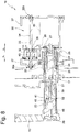
- the armrest 10 comprises a guide device 17 (see Fig. 7 ), by means of which the armrest 13 in the longitudinal direction of the pivot axis a when moving in the direction y 1 and y 2 between a proximal position according to Fig. 7 and a distal position Fig. 8 is guided and with which the armrest 13 according to the movement in the pivoting directions u1 and u2 between a primary position Fig. 8 and a secondary position Fig. 9 is led.
- the guide device 17 comprises second guide means in the form of a sleeve 18 which is fixedly connected to the armrest 13 by means of a fastening 26 via an end piece of the sleeve 18, and first guide means in the form of a sleeve 20 which are fixedly connected to a base 19.
- the base 19 comprises in this exemplary embodiment, a housing 37 which is firmly connected to the structure of the backrest 11.
- the sleeves 18 and 20 are arranged coaxially to the pivot axis a and are telescopically movable, ie the sleeve 18 is movable relative to the sleeve 20 in the direction y 1 and y 2 .
- a spring 21 of a drive device 30 can be seen, which is arranged coaxially to the pivot axis a.
- the spring 21 is supported with a spring end 22 on a contact surface 41 of a profile element 43 of a tie rod 23, which is also part of the drive device 30.
- the tie rod 23 is firmly connected to the drive part 29.
- the spring 21 is supported on a stop surface 25 which is firmly connected to the sleeve 18.
- the sleeve 18 has a stop surface 27, which according to Fig. 7 cooperates with a driving surface 28 of a drive part 29 of the drive device 30.
- the profile element 43 is - e.g. by means of a spline profile - rotatably connected to the sleeve 18. In this way, the pivoting movement of the armrest 13 in the direction u1 is damped by a damper 39.
- a driver 45 of the damper is rotatably connected to the profile element 43.
- a spring 31 can also be seen, which loads the armrest 13 in the pivoting direction u 1 .
- the spring 31 is designed as a torsion spring and is supported with one spring end on the base 19, for example on the housing 37, and with another spring end on the sleeve 18.
- the drive device 30 is designed as a linear drive and comprises a motor 32 and a spindle 33.
- the spindle 33 is provided with an external thread 34, which engages with an internal thread 35 of a spindle nut 40 driven by the motor 32, which is mounted on the motor 32 is.
- the motor 32 is firmly connected to the drive part 29.
- the spindle 33 is mounted in bearings 36a and 36b, which are held on the housing 37 of the armrest 10.
- a guide rod 42 which is only indicated by a chain line, serves as an anti-rotation device for the drive part 29.
- a control can be activated, for example, by means of a switch or a sensor.
- This causes the motor 32 to move the spindle nut 40 in a first direction of rotation, so that the drive part 29 fixedly connected to the motor 32 moves along the spindle 33 in the direction y 1 .
- the drive part 29 takes the assembly of sleeve 18, tie rod 23 and springs 21 and 31 and moves it Assembly relative to the sleeve 20 in the direction y 1 from the proximal position according to Fig. 7 into the distal position according to Fig. 8 .
- the sleeve 18 is guided by an axial guide of the guide device 17.
- This comprises a projection 44 formed on the sleeve 18, which engages in a guideway 46 which extends in the direction y1 and is formed in the housing 37.
- the guideway 46 is designed in such a way that the projection 44 has degrees of freedom in the y1 and y2 directions and rotational movement of the sleeve 18 in the u1 and u2 directions is prevented.
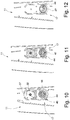
- the guideway 46 ends. Due to the load on the armrest 13 from the spring 31 in the direction u1, the projection 44 is moved into a guide link 47 of the guide device 17, which forms a rotational guide which causes the projection 44 to move in the y directions 1 and y 2 prevented, but allowed movement in the directions u1 and u2.
- the guide link 47 thus locks the return movement of the sleeve 18 in the direction y2.
- the armrest 13 is moved by the spring 31 into the secondary position Fig. 9 moves, the projection 44 in the guide track 47 in the in Fig. 12 position shown moves to one end of the guide track 47.
- the damper 39 brakes the movement of the armrest 13 in the direction u1.
- the armrest 13 could be braked by a separate spring, which is tensioned in this pivoting range until the secondary position is reached.
- the motor 32 is now driven in such a way that the pinion 40 moves the drive part 29 in the direction y 2 , the tie rod 23, which is fixedly connected to the drive part 29, together with the profile element 43 being carried along in the direction y 2 and thereby tensioning the spring 21 (see Fig. 9 ).
- the armrest 13 is pivoted manually against the restoring force of the spring 31 about the pivot axis a in the direction u 2 until the primary position in accordance with Fig. 8 is reached.
- the spring 31 is tensioned again.
- the armrest 13 is moved by the spring 21 in the direction y 2 into the proximal position, the projection 44 running along the guideway 46.
- the armrest of the armrest could be guided with a helical guideway, the movement between the proximal position and the distal position and the movement between the primary position and the secondary position taking place simultaneously.
Landscapes
- Engineering & Computer Science (AREA)
- Aviation & Aerospace Engineering (AREA)
- Transportation (AREA)
- Mechanical Engineering (AREA)
- Seats For Vehicles (AREA)
Applications Claiming Priority (1)
| Application Number | Priority Date | Filing Date | Title |
|---|---|---|---|
| DE102019000119.2A DE102019000119A1 (de) | 2019-01-11 | 2019-01-11 | Armlehne |
Publications (2)
| Publication Number | Publication Date |
|---|---|
| EP3680130A1 true EP3680130A1 (fr) | 2020-07-15 |
| EP3680130B1 EP3680130B1 (fr) | 2021-04-14 |
Family
ID=69147534
Family Applications (1)
| Application Number | Title | Priority Date | Filing Date |
|---|---|---|---|
| EP20150691.2A Active EP3680130B1 (fr) | 2019-01-11 | 2020-01-08 | Accoudoir |
Country Status (4)
| Country | Link |
|---|---|
| US (1) | US11412856B2 (fr) |
| EP (1) | EP3680130B1 (fr) |
| CN (1) | CN111434524B (fr) |
| DE (1) | DE102019000119A1 (fr) |
Families Citing this family (6)
| Publication number | Priority date | Publication date | Assignee | Title |
|---|---|---|---|---|
| DE102021112868A1 (de) | 2021-05-18 | 2022-11-24 | Grammer Aktiengesellschaft | Armlehne |
| CN117261717A (zh) * | 2022-06-15 | 2023-12-22 | 李尔公司 | 具有内部运动阻尼器的扶手组件 |
| CN117261719A (zh) * | 2022-06-15 | 2023-12-22 | 李尔公司 | 具有可调节的安装轴的扶手组件 |
| US11752912B1 (en) * | 2022-08-16 | 2023-09-12 | Ford Global Technologies, Llc | Vehicle seat assembly having assist handle |
| CN116872809B (zh) * | 2023-07-26 | 2026-02-10 | 东风汽车有限公司东风日产乘用车公司 | 扶手总成和座椅 |
| DE102024136303A1 (de) * | 2024-08-30 | 2026-03-05 | Grammer Aktiengesellschaft | Armlehne für einen Fahrzeugsitz |
Citations (5)
| Publication number | Priority date | Publication date | Assignee | Title |
|---|---|---|---|---|
| FR2885329A1 (fr) | 2005-05-04 | 2006-11-10 | Peugeot Citroen Automobiles Sa | Accoudoir a double articulation pour siege de vehicule automobile |
| EP1311177B1 (fr) | 2000-08-25 | 2008-04-30 | Intier Automotive Inc. | Ensemble d'accoudoir retractable et pivotant |
| WO2010147351A2 (fr) * | 2009-06-19 | 2010-12-23 | Kim Hack-Sung | Siège de véhicule |
| DE102007014232B4 (de) | 2006-03-28 | 2011-12-22 | Gm Global Technology Operations Llc (N.D.Ges.D. Staates Delaware) | Verborgene Armlehne |
| DE202015103426U1 (de) | 2015-06-30 | 2015-10-15 | Borgward Trademark Holdings Gmbh | Sitz mit einer verschachtelbaren Armlehne und ein Fahrzeug |
Family Cites Families (14)
| Publication number | Priority date | Publication date | Assignee | Title |
|---|---|---|---|---|
| US4040665A (en) * | 1976-03-12 | 1977-08-09 | General Engineering & Mfg. Corporation | Arm rest assembly for seating structures |
| US4159145A (en) * | 1977-08-29 | 1979-06-26 | Flexsteel Industries, Inc. | Retractible armrest support |
| US6217119B1 (en) * | 1999-10-21 | 2001-04-17 | Paccar Inc | Extendable armrest assembly for a seat |
| US6752462B1 (en) * | 2003-04-04 | 2004-06-22 | Cosco Management, Inc. | Juvenile seat with pivotable armrest |
| JP2005096485A (ja) | 2003-09-22 | 2005-04-14 | Tachi S Co Ltd | 自動車シートに用いるアームレスト |
| US20060267382A1 (en) * | 2005-05-18 | 2006-11-30 | Schukra Of North America | Arm rest return |
| DE102006007893B3 (de) * | 2006-02-21 | 2007-09-27 | Ab Skf | Verstellbare Armlehne |
| DE102008039609A1 (de) * | 2008-08-25 | 2010-03-04 | GM Global Technology Operations, Inc., Detroit | Kraftfahrzeug mit einer Schiebetür und einer verstellbaren Armlehne |
| CN102215718A (zh) * | 2009-05-13 | 2011-10-12 | Cvg管理股份有限公司 | 可调节滑动扶手 |
| WO2015106165A1 (fr) * | 2014-01-09 | 2015-07-16 | InkBed, Inc. | Tabourets, chaises, et leurs procédés d'utilisation |
| US10524573B2 (en) * | 2014-01-09 | 2020-01-07 | InkBed, Inc. | Stools, chairs, and methods using the same |
| CN204801571U (zh) | 2015-07-14 | 2015-11-25 | 合肥云鹤江森汽车座椅有限公司 | 一种隐藏式扶手机构 |
| CN106080315B (zh) | 2016-08-24 | 2018-10-09 | 航宇救生装备有限公司 | 一种长度可调节且能够收藏的座椅扶手 |
| CN206406782U (zh) | 2017-01-12 | 2017-08-15 | 延锋安道拓座椅有限公司 | 一种扶手连接机构 |
-
2019
- 2019-01-11 DE DE102019000119.2A patent/DE102019000119A1/de not_active Ceased
- 2019-12-20 US US16/722,774 patent/US11412856B2/en active Active
-
2020
- 2020-01-08 EP EP20150691.2A patent/EP3680130B1/fr active Active
- 2020-01-10 CN CN202010024097.5A patent/CN111434524B/zh active Active
Patent Citations (5)
| Publication number | Priority date | Publication date | Assignee | Title |
|---|---|---|---|---|
| EP1311177B1 (fr) | 2000-08-25 | 2008-04-30 | Intier Automotive Inc. | Ensemble d'accoudoir retractable et pivotant |
| FR2885329A1 (fr) | 2005-05-04 | 2006-11-10 | Peugeot Citroen Automobiles Sa | Accoudoir a double articulation pour siege de vehicule automobile |
| DE102007014232B4 (de) | 2006-03-28 | 2011-12-22 | Gm Global Technology Operations Llc (N.D.Ges.D. Staates Delaware) | Verborgene Armlehne |
| WO2010147351A2 (fr) * | 2009-06-19 | 2010-12-23 | Kim Hack-Sung | Siège de véhicule |
| DE202015103426U1 (de) | 2015-06-30 | 2015-10-15 | Borgward Trademark Holdings Gmbh | Sitz mit einer verschachtelbaren Armlehne und ein Fahrzeug |
Also Published As
| Publication number | Publication date |
|---|---|
| US20200345146A1 (en) | 2020-11-05 |
| US11412856B2 (en) | 2022-08-16 |
| DE102019000119A1 (de) | 2020-07-16 |
| CN111434524A (zh) | 2020-07-21 |
| CN111434524B (zh) | 2022-10-28 |
| EP3680130B1 (fr) | 2021-04-14 |
| BR102020000495A2 (pt) | 2020-09-24 |
Similar Documents
| Publication | Publication Date | Title |
|---|---|---|
| EP3680130B1 (fr) | Accoudoir | |
| EP0671292B1 (fr) | Siège arrière de véhicule automobile à dossier en deux parties | |
| DE69712271T2 (de) | Lenksäule zur Verwendung in einem Kraftfahrzeug | |
| DE102012112525B4 (de) | Nutzfahrzeugsitz mit doppelarretierbarem Querschlittenteil | |
| DE102009055973B3 (de) | Lenksäule für ein Kraftfahrzeug | |
| DE102013109630B4 (de) | Fahrzeug mit einer Abweisvorrichtung sowie Abweisvorrichtung | |
| EP1902871B2 (fr) | Attelage | |
| DE2233674A1 (de) | Sitz, insbesondere fuer fahrzeuge | |
| DE102015013362B4 (de) | Kopfstütze für einen Fahrzeugsitz | |
| WO2016001096A1 (fr) | Dispositif de réglage de dossier destiné à un siège et siège de véhicule | |
| DE102009033494A1 (de) | Fahrzeugsitz | |
| DE102018109611B4 (de) | Kopfstütze | |
| DE69916051T2 (de) | Lenkanordnung für fahrzeuge und verfahren zum aufbau einer lenkanordnung | |
| DE4129497A1 (de) | 4-wege-sitzhoehenverstellung fuer einen fahrzeugsitz | |
| EP4091875B1 (fr) | Accoudoir | |
| DE19719999C2 (de) | Verschluß für Öffnungseinrichtung in Fahrzeugen | |
| DE202006010184U1 (de) | Drehkonsole | |
| DE102019110202B3 (de) | Lenksäule für ein Kraftfahrzeug | |
| EP1868869B1 (fr) | Disposition d'une colonne de direction | |
| DE102017009580B4 (de) | Kopfstütze für einen Sitz | |
| DE2742380C2 (de) | Verstellvorrichtung für die Pedale von Kraftfahrzeugen | |
| DE102019121296B4 (de) | Entriegelungshebel zum entriegeln wenigstens einer verriegelungsvorrichtung eines fahrzeugsitzes, längseinsteller für einen fahrzeugsitz sowie fahrzeugsitz | |
| DE10055188A1 (de) | Querkraftfreier Antrieb | |
| DE4302549C1 (de) | Klappbare Kopfstütze | |
| EP1721806A2 (fr) | Arrangement de colonne de direction |
Legal Events
| Date | Code | Title | Description |
|---|---|---|---|
| PUAI | Public reference made under article 153(3) epc to a published international application that has entered the european phase |
Free format text: ORIGINAL CODE: 0009012 |
|
| STAA | Information on the status of an ep patent application or granted ep patent |
Free format text: STATUS: THE APPLICATION HAS BEEN PUBLISHED |
|
| AK | Designated contracting states |
Kind code of ref document: A1 Designated state(s): AL AT BE BG CH CY CZ DE DK EE ES FI FR GB GR HR HU IE IS IT LI LT LU LV MC MK MT NL NO PL PT RO RS SE SI SK SM TR |
|
| AX | Request for extension of the european patent |
Extension state: BA ME |
|
| STAA | Information on the status of an ep patent application or granted ep patent |
Free format text: STATUS: REQUEST FOR EXAMINATION WAS MADE |
|
| 17P | Request for examination filed |
Effective date: 20201005 |
|
| RBV | Designated contracting states (corrected) |
Designated state(s): AL AT BE BG CH CY CZ DE DK EE ES FI FR GB GR HR HU IE IS IT LI LT LU LV MC MK MT NL NO PL PT RO RS SE SI SK SM TR |
|
| GRAP | Despatch of communication of intention to grant a patent |
Free format text: ORIGINAL CODE: EPIDOSNIGR1 |
|
| STAA | Information on the status of an ep patent application or granted ep patent |
Free format text: STATUS: GRANT OF PATENT IS INTENDED |
|
| RAP1 | Party data changed (applicant data changed or rights of an application transferred) |
Owner name: GRAMMER AG |
|
| INTG | Intention to grant announced |
Effective date: 20210114 |
|
| GRAS | Grant fee paid |
Free format text: ORIGINAL CODE: EPIDOSNIGR3 |
|
| GRAA | (expected) grant |
Free format text: ORIGINAL CODE: 0009210 |
|
| STAA | Information on the status of an ep patent application or granted ep patent |
Free format text: STATUS: THE PATENT HAS BEEN GRANTED |
|
| AK | Designated contracting states |
Kind code of ref document: B1 Designated state(s): AL AT BE BG CH CY CZ DE DK EE ES FI FR GB GR HR HU IE IS IT LI LT LU LV MC MK MT NL NO PL PT RO RS SE SI SK SM TR |
|
| REG | Reference to a national code |
Ref country code: GB Ref legal event code: FG4D Free format text: NOT ENGLISH |
|
| REG | Reference to a national code |
Ref country code: CH Ref legal event code: EP |
|
| REG | Reference to a national code |
Ref country code: DE Ref legal event code: R096 Ref document number: 502020000026 Country of ref document: DE |
|
| REG | Reference to a national code |
Ref country code: IE Ref legal event code: FG4D Free format text: LANGUAGE OF EP DOCUMENT: GERMAN |
|
| REG | Reference to a national code |
Ref country code: AT Ref legal event code: REF Ref document number: 1382065 Country of ref document: AT Kind code of ref document: T Effective date: 20210515 |
|
| REG | Reference to a national code |
Ref country code: SE Ref legal event code: TRGR |
|
| REG | Reference to a national code |
Ref country code: LT Ref legal event code: MG9D |
|
| REG | Reference to a national code |
Ref country code: NL Ref legal event code: MP Effective date: 20210414 |
|
| PG25 | Lapsed in a contracting state [announced via postgrant information from national office to epo] |
Ref country code: HR Free format text: LAPSE BECAUSE OF FAILURE TO SUBMIT A TRANSLATION OF THE DESCRIPTION OR TO PAY THE FEE WITHIN THE PRESCRIBED TIME-LIMIT Effective date: 20210414 Ref country code: LT Free format text: LAPSE BECAUSE OF FAILURE TO SUBMIT A TRANSLATION OF THE DESCRIPTION OR TO PAY THE FEE WITHIN THE PRESCRIBED TIME-LIMIT Effective date: 20210414 Ref country code: FI Free format text: LAPSE BECAUSE OF FAILURE TO SUBMIT A TRANSLATION OF THE DESCRIPTION OR TO PAY THE FEE WITHIN THE PRESCRIBED TIME-LIMIT Effective date: 20210414 Ref country code: NL Free format text: LAPSE BECAUSE OF FAILURE TO SUBMIT A TRANSLATION OF THE DESCRIPTION OR TO PAY THE FEE WITHIN THE PRESCRIBED TIME-LIMIT Effective date: 20210414 Ref country code: BG Free format text: LAPSE BECAUSE OF FAILURE TO SUBMIT A TRANSLATION OF THE DESCRIPTION OR TO PAY THE FEE WITHIN THE PRESCRIBED TIME-LIMIT Effective date: 20210714 |
|
| PG25 | Lapsed in a contracting state [announced via postgrant information from national office to epo] |
Ref country code: PT Free format text: LAPSE BECAUSE OF FAILURE TO SUBMIT A TRANSLATION OF THE DESCRIPTION OR TO PAY THE FEE WITHIN THE PRESCRIBED TIME-LIMIT Effective date: 20210816 Ref country code: RS Free format text: LAPSE BECAUSE OF FAILURE TO SUBMIT A TRANSLATION OF THE DESCRIPTION OR TO PAY THE FEE WITHIN THE PRESCRIBED TIME-LIMIT Effective date: 20210414 Ref country code: PL Free format text: LAPSE BECAUSE OF FAILURE TO SUBMIT A TRANSLATION OF THE DESCRIPTION OR TO PAY THE FEE WITHIN THE PRESCRIBED TIME-LIMIT Effective date: 20210414 Ref country code: LV Free format text: LAPSE BECAUSE OF FAILURE TO SUBMIT A TRANSLATION OF THE DESCRIPTION OR TO PAY THE FEE WITHIN THE PRESCRIBED TIME-LIMIT Effective date: 20210414 Ref country code: NO Free format text: LAPSE BECAUSE OF FAILURE TO SUBMIT A TRANSLATION OF THE DESCRIPTION OR TO PAY THE FEE WITHIN THE PRESCRIBED TIME-LIMIT Effective date: 20210714 Ref country code: IS Free format text: LAPSE BECAUSE OF FAILURE TO SUBMIT A TRANSLATION OF THE DESCRIPTION OR TO PAY THE FEE WITHIN THE PRESCRIBED TIME-LIMIT Effective date: 20210814 Ref country code: GR Free format text: LAPSE BECAUSE OF FAILURE TO SUBMIT A TRANSLATION OF THE DESCRIPTION OR TO PAY THE FEE WITHIN THE PRESCRIBED TIME-LIMIT Effective date: 20210715 |
|
| REG | Reference to a national code |
Ref country code: DE Ref legal event code: R097 Ref document number: 502020000026 Country of ref document: DE |
|
| PG25 | Lapsed in a contracting state [announced via postgrant information from national office to epo] |
Ref country code: SK Free format text: LAPSE BECAUSE OF FAILURE TO SUBMIT A TRANSLATION OF THE DESCRIPTION OR TO PAY THE FEE WITHIN THE PRESCRIBED TIME-LIMIT Effective date: 20210414 Ref country code: ES Free format text: LAPSE BECAUSE OF FAILURE TO SUBMIT A TRANSLATION OF THE DESCRIPTION OR TO PAY THE FEE WITHIN THE PRESCRIBED TIME-LIMIT Effective date: 20210414 Ref country code: EE Free format text: LAPSE BECAUSE OF FAILURE TO SUBMIT A TRANSLATION OF THE DESCRIPTION OR TO PAY THE FEE WITHIN THE PRESCRIBED TIME-LIMIT Effective date: 20210414 Ref country code: CZ Free format text: LAPSE BECAUSE OF FAILURE TO SUBMIT A TRANSLATION OF THE DESCRIPTION OR TO PAY THE FEE WITHIN THE PRESCRIBED TIME-LIMIT Effective date: 20210414 Ref country code: DK Free format text: LAPSE BECAUSE OF FAILURE TO SUBMIT A TRANSLATION OF THE DESCRIPTION OR TO PAY THE FEE WITHIN THE PRESCRIBED TIME-LIMIT Effective date: 20210414 Ref country code: SM Free format text: LAPSE BECAUSE OF FAILURE TO SUBMIT A TRANSLATION OF THE DESCRIPTION OR TO PAY THE FEE WITHIN THE PRESCRIBED TIME-LIMIT Effective date: 20210414 Ref country code: RO Free format text: LAPSE BECAUSE OF FAILURE TO SUBMIT A TRANSLATION OF THE DESCRIPTION OR TO PAY THE FEE WITHIN THE PRESCRIBED TIME-LIMIT Effective date: 20210414 |
|
| PLBE | No opposition filed within time limit |
Free format text: ORIGINAL CODE: 0009261 |
|
| STAA | Information on the status of an ep patent application or granted ep patent |
Free format text: STATUS: NO OPPOSITION FILED WITHIN TIME LIMIT |
|
| 26N | No opposition filed |
Effective date: 20220117 |
|
| PG25 | Lapsed in a contracting state [announced via postgrant information from national office to epo] |
Ref country code: IS Free format text: LAPSE BECAUSE OF FAILURE TO SUBMIT A TRANSLATION OF THE DESCRIPTION OR TO PAY THE FEE WITHIN THE PRESCRIBED TIME-LIMIT Effective date: 20210814 Ref country code: AL Free format text: LAPSE BECAUSE OF FAILURE TO SUBMIT A TRANSLATION OF THE DESCRIPTION OR TO PAY THE FEE WITHIN THE PRESCRIBED TIME-LIMIT Effective date: 20210414 |
|
| PG25 | Lapsed in a contracting state [announced via postgrant information from national office to epo] |
Ref country code: MC Free format text: LAPSE BECAUSE OF FAILURE TO SUBMIT A TRANSLATION OF THE DESCRIPTION OR TO PAY THE FEE WITHIN THE PRESCRIBED TIME-LIMIT Effective date: 20210414 |
|
| REG | Reference to a national code |
Ref country code: BE Ref legal event code: MM Effective date: 20220131 |
|
| PG25 | Lapsed in a contracting state [announced via postgrant information from national office to epo] |
Ref country code: LU Free format text: LAPSE BECAUSE OF NON-PAYMENT OF DUE FEES Effective date: 20220108 |
|
| PG25 | Lapsed in a contracting state [announced via postgrant information from national office to epo] |
Ref country code: BE Free format text: LAPSE BECAUSE OF NON-PAYMENT OF DUE FEES Effective date: 20220131 |
|
| PG25 | Lapsed in a contracting state [announced via postgrant information from national office to epo] |
Ref country code: IE Free format text: LAPSE BECAUSE OF NON-PAYMENT OF DUE FEES Effective date: 20220108 |
|
| P01 | Opt-out of the competence of the unified patent court (upc) registered |
Effective date: 20230530 |
|
| REG | Reference to a national code |
Ref country code: CH Ref legal event code: PL |
|
| PG25 | Lapsed in a contracting state [announced via postgrant information from national office to epo] |
Ref country code: LI Free format text: LAPSE BECAUSE OF NON-PAYMENT OF DUE FEES Effective date: 20230131 Ref country code: CH Free format text: LAPSE BECAUSE OF NON-PAYMENT OF DUE FEES Effective date: 20230131 |
|
| PG25 | Lapsed in a contracting state [announced via postgrant information from national office to epo] |
Ref country code: MK Free format text: LAPSE BECAUSE OF FAILURE TO SUBMIT A TRANSLATION OF THE DESCRIPTION OR TO PAY THE FEE WITHIN THE PRESCRIBED TIME-LIMIT Effective date: 20210414 Ref country code: CY Free format text: LAPSE BECAUSE OF FAILURE TO SUBMIT A TRANSLATION OF THE DESCRIPTION OR TO PAY THE FEE WITHIN THE PRESCRIBED TIME-LIMIT Effective date: 20210414 |
|
| PG25 | Lapsed in a contracting state [announced via postgrant information from national office to epo] |
Ref country code: HU Free format text: LAPSE BECAUSE OF FAILURE TO SUBMIT A TRANSLATION OF THE DESCRIPTION OR TO PAY THE FEE WITHIN THE PRESCRIBED TIME-LIMIT; INVALID AB INITIO Effective date: 20200108 |
|
| PG25 | Lapsed in a contracting state [announced via postgrant information from national office to epo] |
Ref country code: MT Free format text: LAPSE BECAUSE OF FAILURE TO SUBMIT A TRANSLATION OF THE DESCRIPTION OR TO PAY THE FEE WITHIN THE PRESCRIBED TIME-LIMIT Effective date: 20210414 |
|
| PGFP | Annual fee paid to national office [announced via postgrant information from national office to epo] |
Ref country code: AT Payment date: 20250417 Year of fee payment: 5 |
|
| REG | Reference to a national code |
Ref country code: AT Ref legal event code: MM01 Ref document number: 1382065 Country of ref document: AT Kind code of ref document: T Effective date: 20250108 |
|
| PGFP | Annual fee paid to national office [announced via postgrant information from national office to epo] |
Ref country code: SE Payment date: 20260121 Year of fee payment: 7 |
|
| PGFP | Annual fee paid to national office [announced via postgrant information from national office to epo] |
Ref country code: GB Payment date: 20260122 Year of fee payment: 7 |
|
| PGFP | Annual fee paid to national office [announced via postgrant information from national office to epo] |
Ref country code: DE Payment date: 20260120 Year of fee payment: 7 |
|
| PG25 | Lapsed in a contracting state [announced via postgrant information from national office to epo] |
Ref country code: AT Free format text: LAPSE BECAUSE OF NON-PAYMENT OF DUE FEES Effective date: 20250108 |
|
| PGFP | Annual fee paid to national office [announced via postgrant information from national office to epo] |
Ref country code: IT Payment date: 20260130 Year of fee payment: 7 |
|
| PGFP | Annual fee paid to national office [announced via postgrant information from national office to epo] |
Ref country code: FR Payment date: 20260121 Year of fee payment: 7 |
|
| PGFP | Annual fee paid to national office [announced via postgrant information from national office to epo] |
Ref country code: TR Payment date: 20260107 Year of fee payment: 7 |