EP3680170A1 - Système de commande de train d'atterrissage et procédé de commande de train d'atterrissage - Google Patents
Système de commande de train d'atterrissage et procédé de commande de train d'atterrissage Download PDFInfo
- Publication number
- EP3680170A1 EP3680170A1 EP20158608.8A EP20158608A EP3680170A1 EP 3680170 A1 EP3680170 A1 EP 3680170A1 EP 20158608 A EP20158608 A EP 20158608A EP 3680170 A1 EP3680170 A1 EP 3680170A1
- Authority
- EP
- European Patent Office
- Prior art keywords
- drive system
- gears
- gear
- drive
- landing gear
- Prior art date
- Legal status (The legal status is an assumption and is not a legal conclusion. Google has not performed a legal analysis and makes no representation as to the accuracy of the status listed.)
- Withdrawn
Links
Images






Classifications
-
- B—PERFORMING OPERATIONS; TRANSPORTING
- B64—AIRCRAFT; AVIATION; COSMONAUTICS
- B64C—AEROPLANES; HELICOPTERS
- B64C25/00—Alighting gear
- B64C25/32—Alighting gear characterised by elements which contact the ground or similar surface
- B64C25/405—Powered wheels, e.g. for taxing
-
- B—PERFORMING OPERATIONS; TRANSPORTING
- B64—AIRCRAFT; AVIATION; COSMONAUTICS
- B64C—AEROPLANES; HELICOPTERS
- B64C25/00—Alighting gear
- B64C25/32—Alighting gear characterised by elements which contact the ground or similar surface
- B64C25/34—Alighting gear characterised by elements which contact the ground or similar surface wheeled type, e.g. multi-wheeled bogies
-
- F—MECHANICAL ENGINEERING; LIGHTING; HEATING; WEAPONS; BLASTING
- F16—ENGINEERING ELEMENTS AND UNITS; GENERAL MEASURES FOR PRODUCING AND MAINTAINING EFFECTIVE FUNCTIONING OF MACHINES OR INSTALLATIONS; THERMAL INSULATION IN GENERAL
- F16H—GEARING
- F16H1/00—Toothed gearings for conveying rotary motion
- F16H1/02—Toothed gearings for conveying rotary motion without gears having orbital motion
- F16H1/04—Toothed gearings for conveying rotary motion without gears having orbital motion involving only two intermeshing members
- F16H1/06—Toothed gearings for conveying rotary motion without gears having orbital motion involving only two intermeshing members with parallel axes
-
- F—MECHANICAL ENGINEERING; LIGHTING; HEATING; WEAPONS; BLASTING
- F16—ENGINEERING ELEMENTS AND UNITS; GENERAL MEASURES FOR PRODUCING AND MAINTAINING EFFECTIVE FUNCTIONING OF MACHINES OR INSTALLATIONS; THERMAL INSULATION IN GENERAL
- F16H—GEARING
- F16H1/00—Toothed gearings for conveying rotary motion
- F16H1/02—Toothed gearings for conveying rotary motion without gears having orbital motion
- F16H1/26—Special means compensating for misalignment of axes
-
- F—MECHANICAL ENGINEERING; LIGHTING; HEATING; WEAPONS; BLASTING
- F16—ENGINEERING ELEMENTS AND UNITS; GENERAL MEASURES FOR PRODUCING AND MAINTAINING EFFECTIVE FUNCTIONING OF MACHINES OR INSTALLATIONS; THERMAL INSULATION IN GENERAL
- F16H—GEARING
- F16H55/00—Elements with teeth or friction surfaces for conveying motion; Worms, pulleys or sheaves for gearing mechanisms
- F16H55/02—Toothed members; Worms
- F16H55/10—Constructively simple tooth shapes, e.g. shaped as pins, as balls
-
- F—MECHANICAL ENGINEERING; LIGHTING; HEATING; WEAPONS; BLASTING
- F16—ENGINEERING ELEMENTS AND UNITS; GENERAL MEASURES FOR PRODUCING AND MAINTAINING EFFECTIVE FUNCTIONING OF MACHINES OR INSTALLATIONS; THERMAL INSULATION IN GENERAL
- F16H—GEARING
- F16H57/00—General details of gearing
- F16H57/0006—Vibration-damping or noise reducing means specially adapted for gearings
-
- F—MECHANICAL ENGINEERING; LIGHTING; HEATING; WEAPONS; BLASTING
- F16—ENGINEERING ELEMENTS AND UNITS; GENERAL MEASURES FOR PRODUCING AND MAINTAINING EFFECTIVE FUNCTIONING OF MACHINES OR INSTALLATIONS; THERMAL INSULATION IN GENERAL
- F16H—GEARING
- F16H57/00—General details of gearing
- F16H57/0018—Shaft assemblies for gearings
- F16H57/0037—Special features of coaxial shafts, e.g. relative support thereof
-
- F—MECHANICAL ENGINEERING; LIGHTING; HEATING; WEAPONS; BLASTING
- F16—ENGINEERING ELEMENTS AND UNITS; GENERAL MEASURES FOR PRODUCING AND MAINTAINING EFFECTIVE FUNCTIONING OF MACHINES OR INSTALLATIONS; THERMAL INSULATION IN GENERAL
- F16H—GEARING
- F16H57/00—General details of gearing
- F16H57/01—Monitoring wear or stress of gearing elements, e.g. for triggering maintenance
-
- F—MECHANICAL ENGINEERING; LIGHTING; HEATING; WEAPONS; BLASTING
- F16—ENGINEERING ELEMENTS AND UNITS; GENERAL MEASURES FOR PRODUCING AND MAINTAINING EFFECTIVE FUNCTIONING OF MACHINES OR INSTALLATIONS; THERMAL INSULATION IN GENERAL
- F16H—GEARING
- F16H57/00—General details of gearing
- F16H57/02—Gearboxes; Mounting gearing therein
- F16H57/021—Shaft support structures, e.g. partition walls, bearing eyes, casing walls or covers with bearings
- F16H57/022—Adjustment of gear shafts or bearings
-
- F—MECHANICAL ENGINEERING; LIGHTING; HEATING; WEAPONS; BLASTING
- F16—ENGINEERING ELEMENTS AND UNITS; GENERAL MEASURES FOR PRODUCING AND MAINTAINING EFFECTIVE FUNCTIONING OF MACHINES OR INSTALLATIONS; THERMAL INSULATION IN GENERAL
- F16H—GEARING
- F16H57/00—General details of gearing
- F16H57/12—Arrangements for adjusting or for taking-up backlash not provided for elsewhere
-
- F—MECHANICAL ENGINEERING; LIGHTING; HEATING; WEAPONS; BLASTING
- F16—ENGINEERING ELEMENTS AND UNITS; GENERAL MEASURES FOR PRODUCING AND MAINTAINING EFFECTIVE FUNCTIONING OF MACHINES OR INSTALLATIONS; THERMAL INSULATION IN GENERAL
- F16H—GEARING
- F16H57/00—General details of gearing
- F16H57/0006—Vibration-damping or noise reducing means specially adapted for gearings
- F16H2057/0012—Vibration-damping or noise reducing means specially adapted for gearings for reducing drive line oscillations
-
- F—MECHANICAL ENGINEERING; LIGHTING; HEATING; WEAPONS; BLASTING
- F16—ENGINEERING ELEMENTS AND UNITS; GENERAL MEASURES FOR PRODUCING AND MAINTAINING EFFECTIVE FUNCTIONING OF MACHINES OR INSTALLATIONS; THERMAL INSULATION IN GENERAL
- F16H—GEARING
- F16H57/00—General details of gearing
- F16H57/01—Monitoring wear or stress of gearing elements, e.g. for triggering maintenance
- F16H2057/012—Monitoring wear or stress of gearing elements, e.g. for triggering maintenance of gearings
-
- F—MECHANICAL ENGINEERING; LIGHTING; HEATING; WEAPONS; BLASTING
- F16—ENGINEERING ELEMENTS AND UNITS; GENERAL MEASURES FOR PRODUCING AND MAINTAINING EFFECTIVE FUNCTIONING OF MACHINES OR INSTALLATIONS; THERMAL INSULATION IN GENERAL
- F16H—GEARING
- F16H57/00—General details of gearing
- F16H57/12—Arrangements for adjusting or for taking-up backlash not provided for elsewhere
- F16H2057/123—Arrangements for adjusting or for taking-up backlash not provided for elsewhere using electric control means
-
- Y—GENERAL TAGGING OF NEW TECHNOLOGICAL DEVELOPMENTS; GENERAL TAGGING OF CROSS-SECTIONAL TECHNOLOGIES SPANNING OVER SEVERAL SECTIONS OF THE IPC; TECHNICAL SUBJECTS COVERED BY FORMER USPC CROSS-REFERENCE ART COLLECTIONS [XRACs] AND DIGESTS
- Y02—TECHNOLOGIES OR APPLICATIONS FOR MITIGATION OR ADAPTATION AGAINST CLIMATE CHANGE
- Y02T—CLIMATE CHANGE MITIGATION TECHNOLOGIES RELATED TO TRANSPORTATION
- Y02T50/00—Aeronautics or air transport
- Y02T50/80—Energy efficient operational measures, e.g. ground operations or mission management
Definitions
- the present invention relates to a drive system for rotating one or more wheels of an aircraft landing gear for the purposes of ground taxiing (forwards or reverse) and/or wheel spin-up prior to landing and/or for applying braking torque to the rotating wheel(s).
- the invention also relates to a method of operating the landing gear.
- Aircraft are required to ground taxi between locations on airfields.
- An example is taxiing between a runway and the location (e.g. terminal gate) at which the aircraft's passengers are to board or disembark.
- Such taxiing is achieved by using the thrust from the aircraft's engines to propel the aircraft forwards so that the landing gear wheels are caused to rotate.
- ground taxi speeds are necessarily relatively low, the engines must be run at a very low power. This means that there is a relatively high fuel consumption as a result of the poor propulsion efficiency at this low power. This leads to an increased level of both atmospheric and noise pollution locally around airports.
- even when the engines are run at low power it is generally necessary to apply the wheel brakes to limit ground taxi speeds, leading to a high degree of brake wear.
- Transmission error is a measurement of the consistency of an output rotation from a transmission for a constant input. For a constant rotational input, transmission error results in a non-constant rotational output, where an output of a transmission shows variations in speed or torque. These variations can be defined as transmission error and can be measured in units of minutes of arc or arcmin, which equates to one sixtieth of a degree. The transmission error can be expressed as a variation in output rotation which can be expected for a known input rotation.
- the centre distance is typically selected to minimise the transmission error.
- at least one of the gears has a non-fixed centre. This may be due to a variety of factors, e.g. the need to radially separate the gears when gear engagement is undesirable, and/or the need to accommodate ovalisation of at least one of the gears under load. Under these circumstances it has been found that the transmission error would otherwise reach unacceptable levels without the actuator and controller for dynamically adjusting the centre distances of the gears to minimise the transmission error.
- the first gear may be a roller gear comprising a series of rollers arranged to form a ring, each roller being rotatable about a roller axis located at a fixed distance from the rotational axis of the first gear; and the second gear may be a sprocket comprising an array of sprocket teeth for engagement with the rollers of the first gear.
- first and second gears may be spur gears, or other toothed gears.
- a key advantage of achieving the drive via a sprocket and roller gear is that such a mechanism is inherently robust and tolerant of environmental contamination. Thus, it may not be necessary to enclose the drive system within a casing to prevent ingress of debris and other contaminants.
- Another advantage of the sprocket-roller arrangement is that it is more tolerant of wheel deformation and misalignment between pinion and driven gear than meshing toothed gear arrangements.
- Landing gear wheels are subject to high loads and consequential deformation during ground taxiing, and a driven gear fixed to the wheel will inevitably deform in response to such wheel deformation.
- Meshing gears are generally intolerant of such deformation and so the wheel rim gear may need to be isolated from the wheel via bearings, a flexible interface, or similar, to avoid excessive ovalisation of the wheel rim gear. Deformation of the wheel mounted gear (whether with a flexible interface or directly attached to the wheel) poses a challenge for meshing engagement with the drive pinion without introducing high transmission error and vibration.
- movement of the landing gear drive system in the first configuration may be limited by a stop, and the actuator for adjusting the distance between rotational axes of the first and second gears may be coupled to the stop for moving the stop. Movement of the stop thereby adjusts the distance between the rotational axes of the first and second gears.
- the drive transmission may be mounted externally on the landing gear on either the sprung part (e.g. the strut) or on the un-sprung part (e.g. the slider or axle or bogie).
- the drive system may be pivotally mounted on the landing gear.
- the output shaft carrying the drive pinion may rotate about a substantially horizontal pivot axis displaced from the axis of rotation of the drive pinion.
- the first and second gears may move into and out of engagement by rotation about the pivot axis.
- the motor may move with the drive pinion about the pivot axis, or alternatively the motor may be static with respect to the pivot axis, or further alternatively the motor may rotate about the pivot axis as the drive pinion moves through an arc centred on the pivot axis.
- the landing gear may have only one driveable wheel. Alternatively, two or more of the landing gear wheels may be driven by one or more motors. A differential may be used between the motor(s) and the drive pinions.
- the motor may be electric or hydraulic, for example.
- the landing gear When incorporated on an aircraft, the landing gear may be used with a power and control system for supplying power to, and controlling operation of, the drive transmission.
- the illustrated embodiments are shown applied to an aircraft landing gear which has two wheels, but the principles of the embodiments may be applied to landing gear with any number of wheels including only a single wheel.
- the embodiments are applied to a main landing gear (i.e. a landing gear attached to wing structure or fuselage structure in the region of the wings), since the weight supported by the main landing gear is considered to provide the best traction between the wheels and the ground to enable reliable aircraft ground taxiing.
- the drive system of the present invention may alternatively be applied to a nose landing gear (i.e. a steerable landing gear towards the nose of the aircraft).
- the landing gear 10 includes a telescopic shock absorbing main leg 12, including an upper telescopic part 12a (main fitting) and a lower telescopic part 12b (the slider).
- the upper telescopic part 12a is attached to the aircraft fuselage or wing (not shown) by its upper end (not shown).
- the lower telescopic part 12b supports an axle 14 carrying a pair of wheels 16, one on either side of the main leg (only one wheel 16 is shown in Figures 1 and 2 , for clarity).
- the wheels 16 are arranged to rotate about the axle 14 to enable ground movement of the aircraft, such as taxiing or landing.
- Each wheel 16 comprises a tyre 17 supported by a hub 18 having a rim 18a at its outer edge which holds the tyre 17.
- a driven gear 20 is attached to the hub 18 (preferably at the rim 18a) so as to be rotatable with the wheel 16.
- the driven gear 20 may be attached to the wheel 16 by a plurality of discrete couplings, which may provide a rigid or flexible attachment. Alternatively, the attachment may be via a flange forming a continuous extension rim projecting axially from either the wheel 16 or the driven gear 20.
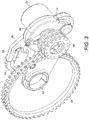
- a drive pinion 60 is mounted on the drive shaft 54 so as to be rotatable by the drive shaft about a drive axis.
- the drive pinion 60, drive shaft 54 and gearbox 70 are pivotable by a linear actuator (positioner) 58, such as a direct drive roller screw electro mechanical linear actuator, extends between the bracket 56 (at an end nearest the axle 15) and the gearbox 70, or more particularly the housing 84 of the gearbox.
- linear actuator 58 is translated into rotational movement of the gearbox 70 and the sprockets 60 about the pivot 82.
- the drive system 50 can therefore be between a neutral configuration (not shown) in which the drive pinion 60 does not mesh with the driven gear 20, and a driven configuration (shown in Figures 1 , 2 and 3 ) in which the drive pinion 60 is in meshed engagement with the driven gear 20.
- a neutral configuration (not shown) in which the drive pinion 60 does not mesh with the driven gear 20
- a driven configuration shown in Figures 1 , 2 and 3
- the wheel 16 In the neutral configuration the wheel 16 is able to rotate freely, e.g. during take-off and landing, while in the driven configuration the wheel 16 can be driven by the drive system 50, e.g. during ground taxiing.
- the roller gear 24 is formed by a rigid annular ring 35 and a series of pins 28 projecting from both sides of the annular ring 35.
- a first series of rollers 36a rotatably supported by the pins 38 is provided on one side of the annular ring 35, and a second series of rollers 36b rotatably supported by the pins as provided on the other side of the annular ring.
- Each series of rollers 36a, 36b extends around the annular ring to form a continuous track.
- First and second lateral annular rings 39a, 39b sandwich the first and second series of rollers 36a, 36b.
- the pins 38 supporting the first series of rollers 36a extend between the annular ring 35 and the first lateral annular ring 39a, and the pins 38 supporting the second series of rollers 36b extend between the annular ring 35 and the second lateral annular ring 39b.
- the annular ring 35 therefore forms a central spine for supporting the pins which are cantilevered off the central spine.
- the annular ring 35 comprises a plurality of axially extending connection extension tabs (not shown) providing mounting means for mounting the roller gear 34 to the hub 18. Alternatively, the tabs may be substituted for the annular ring 35.
- An advantage of the sprocket-roller gear arrangement is that it is more tolerant of wheel and axle deformation than meshing toothed gear arrangements. Landing gear wheels and axles are subject to high loads and consequential deformation during ground taxiing, and a driven gear fixed to the wheel will inevitably deform in response to such deformation. Meshing toothed gears are intolerant of such deformation and a typical toothed rim gear may need to be isolated from the wheel via bearings, a flexible interface, or similar. In contrast, the sprocket and roller arrangement of the present invention may be able to tolerate the deformation without such modification.
- rollers Such an arrangement also has the advantage of being lightweight and having high structural strength.
- the main failure mode of the rollers is via shear failure of the pins; by mounting each roller directly on its respective pin, with no intermediate sleeve, bush or other part, the diameter of the pin can be maximised to maximise shear strength.
- the delivered torque varies both as each roller moves along a tooth profile, and as each roller engages with or disengages from a tooth.
- Figures 4 to 7 show an example schematic torque profile and illustrate the roller-sprocket tooth dynamics at various significant parts of that profile.
- the roller gear is the drive pinion and the sprocket is the driven gear (as in the embodiment of Figure 3 ).
- the torque profile has a generally periodic or cyclical shape, with each phase (corresponding to the time between each sprocket-roller engagement) containing two maxima (labelled max1 and max2) and two minima (labelled mini and min2).
- Figure 4 shows the relative positions of the rollers and sprocket teeth at the time corresponding to the maximum labelled max1.
- two rollers A, B are engaged with two sprocket teeth Y, Z, respectively.
- Force vector 100 indicates the direction of force transfer between roller B and tooth Y
- force vector 102 indicates the direction of force transfer between roller A and tooth X. It can be seen from force vector 100 that roller B is close to its maximum radial distance from the driven gear centre, but has a force vector angle which is substantially lower than 90 degrees to the local radius of the driven gear.
- Force vector 102 shows that roller A is approaching a minimum radial distance, but has a force vector angle which is near to 90 degrees. The sum of these force vectors 100, 102 provides a torque maximum, max1.
- Figure 7 shows the relative positions of the rollers and sprocket teeth at the second torque minimum, min2.
- roller B has moved still further along the tooth profile of tooth Y, force vector 108 showing that roller B has moved closer to the driven gear centre but with little change to its force vector angle, resulting in a decrease in transferred torque.
- Roller C has moved into engagement with tooth Z, force vector 110 showing that its transferred torque is initially low despite its high distance from the driven gear centre, since its force vector angle is substantially lower than 90 degrees.
- an actual centre distance between the respective meshing gears may be directly measured and compared with an ideal centre distance.
- this will not necessarily take into account deformations in parts of the system, such as a wheel hub, to which the sprocket or roller gears are applied.
- centre distance is not necessarily an accurate indicator of the relative positions of rollers and sprocket teeth when applied to a related drive system.
- a measurement of variations in a rotational velocity of the other gear can indicate variations in transmission error, and so minimising such a signal can minimise transmission error through the drive system and the related vibrations generated by the transmission error.
- a measurement of a difference in rotational velocity between the first and second gears can also indicate a transmission error through the drive system and so this variation can also be measured and minimised by actuation of the actuator 58, to help to minimise variations in transmission efficiency and related vibrations.
- a measurement of a magnitude of the fluctuations illustrated in the graphs of Figures 4 to 7 can be input to an algorithm and adjustments can be made to the actuator to adjust a separation of gears of the transmission in order to minimise the magnitude of the measured fluctuations. This can be done in a closed feedback loop and adjustments made until a minimal magnitude of the variations is found.
- a minimised level variation can therefore generally be achieved.
- the minimum fluctuation which can be achieved may begin to grow over time.
- a suitable output may be generated by a controller to give an indication to either maintenance personnel or to a user of the system that it is time to change components of the system. Therefore, measurement of the described signal can be used to identify a wear condition of the first and/or second gears, or other related components of the drive system.
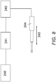
- Figure 8 indicates a schematic diagram of a control system which may be used to implement the control of the drive system of the present invention.
- the control system comprises a controller 241.
- a sensor 242 is arranged to detect at least one parameter indicative of a transmission error through the first and second gears and to generate an output indicative of the sensed parameter.
- the sensed parameter can be any of the measured parameters discussed in the above.
- the output of sensor 242 is input to a controller 241.
- the controller is arranged to process the input signal to arrive at a decision concerning a direction in which actuator 244 should be actuated, if at all. Between actuator 244 and controller 241, there may be a converter 243. This can convert a low power control signal from the controller 241 into a higher power actuation signal, in a different form if necessary.
- the output of converter 243 may be a hydraulic, pneumatic, electrical or mechanical output and generally acts to cause actuator 244 to move in one direction or the other in the directions indicated by arrow 245.
- a linear actuator 244 is shown in the schematic drawing of figure 8 , it will be appreciated that a non-linear, or rotational, actuator can also be used to cause variations in the separation of the first and second gears of the drive system.
- the sensor 242 will give either a constant output, or a periodically sampled output, which is then processed by controller 241 at a certain frequency. Therefore, once adjustments are made to the actuator 244, then variations in the parameter sensed by sensor 242 will be again detected by a sensor and input to the controller.
- the controller may actuate the actuator 244 further in the same direction.
- it may actuate the actuator in the opposite direction to try to reduce the signal variations.
- Further control regimes can be envisaged, which would process the output of the sensor 242 in the controller 241 to actuate the actuator 244 to minimise variations of the signal detected by the sensor 242.
- the actuator 244 (shown in Figure 8 ) which adjusts the distance between respective rotational axes of the gears is the same actuator as actuator 58 which moves the drive system between the neutral configuration in which the drive pinion 60 does not mesh with the driven gear 20, and the driven configuration in which the drive pinion 60 is in meshed engagement with the driven gear 20.
- the actuator 244 may be arranged differently to that described above such that its output is not the same as that of actuator 58 under a common controller.
- the actuator 244 may be used to control the position of a stop that limits the travel of the actuator 58 in the driven configuration of the drive system. By adjusting the stop position the distance between respective rotational axes of the gears is adjusted.
- the stop may be configured in a variety of ways.
- the stop may be a block having a bearing surface which contacts the gearbox 70 to limit rotation of the gearbox 70 about its pivot axis.
- the stop may be a pin at the pivot axis that limits the rotation of the gearbox 70 about its pivot axis.
- the stop may be a blocking element in the actuator 58 that limits the extent of travel of the actuator piston.
- the stop may be configured in any number of similar ways to the same effect.
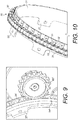
- the drive pinion may be formed as a sprocket 60' (see Figure 9 ) having a single row of teeth
- the driven gear may be formed as a roller gear having a single row of rollers.
- the roller gear may take many forms, including the roller gear 34' of Figure 9 and the roller chain gear 20 variant of Figure 10 .
- a roller chain 30 extends around a rigid annular extension ring 21.
- the roller chain 30 is driven by a single sprocket (not shown) similar to the sprocket 60'.
- the extension ring 21 (or drum) is rigidly attached to the hub 18 via a plurality of extension tabs 22 so that it extends from an outer circumference of the hub 18 towards the leg 12.
- a roller chain 30 is fixed around the outer circumference of the extension ring 21 so that it forms a continuous track around the ring 21.
- the roller chain 30 comprises multiple interlinked chain elements 31, each comprising a sub-assembly of two rollers 32 mounted on parallel axes. Each roller 32 is rotatable about a bush (not shown) which is itself mounted on a pin (not shown).
- Each chain element 31 is pivotally mounted to its neighbouring element by a pair of link elements 33 so that the rollers 32 are arranged to form a continuous track, or series, and each element 31 is thus designed to be able to rotate relative to its neighbour.
- the driven gear may include a plurality of multiple coaxial chains engagable by a pinion formed by multiple coaxial sprockets.
- the embodiments described above are suitable only for ground taxiing operations but could be modified (e.g. by adjustment of the gearbox ratio) to be suitable for only pre-landing spin-up operations.
- the linear actuator 58 (which may be back drivable) may be torque controlled (or current controlled) to apply a substantially constant load between the sprockets 60 and the driven gear 20, thereby allowing for some deformation of the various component parts of the drive system 50 while at the same time preventing unwanted separation.
- An electro mechanical brake (not shown), or other similar blocking device, may be integrated within the actuator 58 to lock the actuator in the disengaged (second) configuration.
- the drive system may include two drive pinions, as shown in Figures 13(A)-(C) .
- the drive system comprises a motor (not shown) which rotates an input shaft which itself rotates first 60 and second 62 output sprockets via a gearbox having two separate drive paths - one for driving the first sprocket 60 and one for driving the second sprocket 62.
- the first 60 and second 62 sprockets are each wheel-type sprockets with radially-extending teeth which can interlock with the rollers 32 of the roller chain 30 (or rollers 36 of roller gear 34). Linear movement of the actuator (not shown) is translated to rotational movement of the drive system.
- the drive system 50 can be rotated between a position in which only the first sprocket 60 engages the roller chain 30 ( Fig. 13A ) and a position in which only the second sprocket 62 engages the roller chain 30 ( Fig. 13C ). In a position between these two extremes neither sprocket 60, 62 engages the roller chain 30 ( Fig. 13B ).
- This pivoting arrangement ensures that it is not possible for both the first sprocket 60 and second sprocket 62 to engage the roller chain 30 at the same time.
- the drive system of figures 13(A)-(C) can be arranged to have three configurations: a low speed, high torque taxiing configuration in which the motor drives the wheel via the first drive path and first sprocket 60 ( Fig. 13A ); a high speed, low torque spin-up configuration in which the motor drives the wheel via the second drive path and second sprocket 62 ( Fig. 13C ); and a neutral (disconnected) configuration in which neither the first sprocket 60 nor the second sprocket 62 engages the roller chain ( Fig. 13B ).
- the figures only show features of the drive system 50 for driving one of the wheels 16, it is envisaged that these features may be mirrored for the other wheel 16. That is, it is envisaged that one drive system 50 may be provided for each wheel 16.
- a drive system 50 may be provided for each of the wheels 16, or for only two of them.
- the drive system 50 may alternatively be mounted on the upper telescopic part 12a (main fitting) or lower telescopic part 12b (slider).
Landscapes
- Engineering & Computer Science (AREA)
- General Engineering & Computer Science (AREA)
- Mechanical Engineering (AREA)
- Aviation & Aerospace Engineering (AREA)
- Gears, Cams (AREA)
- Gear Transmission (AREA)
Applications Claiming Priority (4)
| Application Number | Priority Date | Filing Date | Title |
|---|---|---|---|
| GB1403840.0A GB2523780A (en) | 2014-03-05 | 2014-03-05 | Drive system for landing gear and drive system control method |
| GB1404699.9A GB2523847A (en) | 2014-03-05 | 2014-03-17 | Drive system for landing gear and drive system control method |
| PCT/GB2015/050630 WO2015132590A1 (fr) | 2014-03-05 | 2015-03-05 | Système d'entraînement pour train d'atterrissage et procédé de commande d'enclenchement de système d'entraînement |
| EP15709549.8A EP3114029B1 (fr) | 2014-03-05 | 2015-03-05 | Système d'entraînement pour train d'atterrissage et procédé de commande d'enclenchement de système d'entraînement |
Related Parent Applications (2)
| Application Number | Title | Priority Date | Filing Date |
|---|---|---|---|
| EP15709549.8A Division EP3114029B1 (fr) | 2014-03-05 | 2015-03-05 | Système d'entraînement pour train d'atterrissage et procédé de commande d'enclenchement de système d'entraînement |
| EP15709549.8A Division-Into EP3114029B1 (fr) | 2014-03-05 | 2015-03-05 | Système d'entraînement pour train d'atterrissage et procédé de commande d'enclenchement de système d'entraînement |
Publications (1)
| Publication Number | Publication Date |
|---|---|
| EP3680170A1 true EP3680170A1 (fr) | 2020-07-15 |
Family
ID=50490802
Family Applications (2)
| Application Number | Title | Priority Date | Filing Date |
|---|---|---|---|
| EP15709549.8A Active EP3114029B1 (fr) | 2014-03-05 | 2015-03-05 | Système d'entraînement pour train d'atterrissage et procédé de commande d'enclenchement de système d'entraînement |
| EP20158608.8A Withdrawn EP3680170A1 (fr) | 2014-03-05 | 2015-03-05 | Système de commande de train d'atterrissage et procédé de commande de train d'atterrissage |
Family Applications Before (1)
| Application Number | Title | Priority Date | Filing Date |
|---|---|---|---|
| EP15709549.8A Active EP3114029B1 (fr) | 2014-03-05 | 2015-03-05 | Système d'entraînement pour train d'atterrissage et procédé de commande d'enclenchement de système d'entraînement |
Country Status (5)
| Country | Link |
|---|---|
| US (2) | US10112703B2 (fr) |
| EP (2) | EP3114029B1 (fr) |
| CN (1) | CN106068407B (fr) |
| GB (2) | GB2523780A (fr) |
| WO (1) | WO2015132590A1 (fr) |
Families Citing this family (15)
| Publication number | Priority date | Publication date | Assignee | Title |
|---|---|---|---|---|
| GB2528966A (en) * | 2014-08-07 | 2016-02-10 | Airbus Operations Ltd | Landing gear drive system |
| US9499260B2 (en) * | 2014-10-14 | 2016-11-22 | Honeywell International Inc. | Aircraft landing gear wheel with integral gear drive |
| FR3059385B1 (fr) * | 2016-11-28 | 2019-05-10 | Safran Landing Systems | Procede de generation d'un profil de dent d'une roue engrenant avec un pignon a rouleaux |
| FR3064326B1 (fr) * | 2017-03-22 | 2021-08-13 | Safran Landing Systems | Element d'engrenage a rouleaux |
| US11358710B2 (en) * | 2018-02-23 | 2022-06-14 | The Boeing Company | Methods and apparatus for controlling landing gear retract braking |
| US10933982B2 (en) | 2018-02-26 | 2021-03-02 | The Boeing Company | Methods and apparatus for controlling landing gear retract braking |
| GB2571348A (en) * | 2018-02-27 | 2019-08-28 | Airbus Operations Ltd | A drive system for rotating a wheel of a landing gear |
| FR3079570B1 (fr) * | 2018-03-28 | 2020-04-17 | Safran Landing Systems | Procede d'engagement de deux elements engrenage et dispositif d'entrainement mettant en œuvre un tel procede |
| CN108860652B (zh) * | 2018-06-27 | 2021-06-08 | 成都飞机工业(集团)有限责任公司 | 一种提高前轮转弯系统传动精度的方法 |
| DE102018126705A1 (de) * | 2018-10-25 | 2020-04-30 | Ebm-Papst St. Georgen Gmbh & Co. Kg | Verfahren zur Ermittlung tatsächlicher Zustandswerte |
| GB2584310B (en) * | 2019-05-30 | 2021-06-23 | Airbus Operations Ltd | An aircraft landing gear drive system |
| CN110683035B (zh) * | 2019-11-12 | 2021-06-04 | 中国商用飞机有限责任公司 | 车架式起落架及包括该起落架的飞行器 |
| CN113009926B (zh) * | 2021-02-01 | 2023-08-11 | 湖南汽车工程职业学院 | 一种无人机多传感器的一体化测试计量系统 |
| CN114483913B (zh) * | 2022-01-18 | 2023-05-02 | 南通理工学院 | 一种动力耦合装置用磨损监测的止推机构 |
| CN119703541B (zh) * | 2025-01-20 | 2025-10-28 | 武义西林德机械制造有限公司 | 新能源汽车电池电解液包装容器支架焊接装置及焊接工艺 |
Citations (8)
| Publication number | Priority date | Publication date | Assignee | Title |
|---|---|---|---|---|
| US2895342A (en) * | 1955-07-29 | 1959-07-21 | Thomas S Hayhurst | Gearing |
| US20060065779A1 (en) | 2004-09-28 | 2006-03-30 | The Boeing Company | Powered nose aircraft wheel system |
| WO2011023505A2 (fr) | 2009-08-28 | 2011-03-03 | Airbus Operations Limited | Atterrisseur d'avion |
| EP2527249A1 (fr) * | 2011-05-27 | 2012-11-28 | Airbus Operations S.A.S. | Dispositif d'interface débrayable entre un système de motorisation de roue de train d'atterrissage d'avion et une roue |
| WO2012171589A1 (fr) * | 2011-06-17 | 2012-12-20 | L-3 Communications Magnet-Motor Gmbh | Unité d'entraînement pour roues d'engrenage tournantes d'aéronef |
| EP2551192A2 (fr) * | 2011-07-27 | 2013-01-30 | Honeywell International Inc. | Système de roulement au sol d'avion comprenant une chaîne d'entraînement |
| WO2013013874A1 (fr) * | 2011-07-22 | 2013-01-31 | Schaeffler Technologies AG & Co. KG | Transmission |
| WO2014023941A1 (fr) * | 2012-08-08 | 2014-02-13 | Airbus Operations Limited | Systèmes d'entraînement de train d'atterrissage |
Family Cites Families (7)
| Publication number | Priority date | Publication date | Assignee | Title |
|---|---|---|---|---|
| JPH03213750A (ja) * | 1990-01-19 | 1991-09-19 | Hitachi Ltd | 歯車装置 |
| BR9205342A (pt) * | 1991-06-24 | 1994-03-08 | Caterpillar Inc | Mecanismo de ajuste de folga e conjunto de engrenagens de eixo de cames |
| RO117639B1 (ro) * | 1999-12-20 | 2002-05-30 | St. Constantin Ion | Angrenaj dinţat şi procedeu de realizare a danturii angrenajului |
| US7658124B2 (en) | 2006-07-27 | 2010-02-09 | Caterpillar Inc. | Compliant gear assembly and work machine using same |
| FR2939763B1 (fr) * | 2008-12-16 | 2011-03-18 | Airbus | Train d'atterrissage motorise pour aeronef |
| FR2954752B1 (fr) * | 2009-12-24 | 2012-03-09 | Messier Bugatti | Ensemble de roue et frein pour aeronef equipe d'un dispositif d'entrainement en rotation. |
| US20150210384A1 (en) * | 2014-01-24 | 2015-07-30 | Honeywell International Inc. | Aircraft wheel driving system |
-
2014
- 2014-03-05 GB GB1403840.0A patent/GB2523780A/en not_active Withdrawn
- 2014-03-17 GB GB1404699.9A patent/GB2523847A/en not_active Withdrawn
-
2015
- 2015-03-05 WO PCT/GB2015/050630 patent/WO2015132590A1/fr not_active Ceased
- 2015-03-05 CN CN201580011444.8A patent/CN106068407B/zh not_active Expired - Fee Related
- 2015-03-05 EP EP15709549.8A patent/EP3114029B1/fr active Active
- 2015-03-05 EP EP20158608.8A patent/EP3680170A1/fr not_active Withdrawn
- 2015-03-05 US US15/123,293 patent/US10112703B2/en active Active
-
2018
- 2018-09-28 US US16/145,948 patent/US20190084668A1/en not_active Abandoned
Patent Citations (9)
| Publication number | Priority date | Publication date | Assignee | Title |
|---|---|---|---|---|
| US2895342A (en) * | 1955-07-29 | 1959-07-21 | Thomas S Hayhurst | Gearing |
| US20060065779A1 (en) | 2004-09-28 | 2006-03-30 | The Boeing Company | Powered nose aircraft wheel system |
| WO2011023505A2 (fr) | 2009-08-28 | 2011-03-03 | Airbus Operations Limited | Atterrisseur d'avion |
| EP2527249A1 (fr) * | 2011-05-27 | 2012-11-28 | Airbus Operations S.A.S. | Dispositif d'interface débrayable entre un système de motorisation de roue de train d'atterrissage d'avion et une roue |
| WO2012171589A1 (fr) * | 2011-06-17 | 2012-12-20 | L-3 Communications Magnet-Motor Gmbh | Unité d'entraînement pour roues d'engrenage tournantes d'aéronef |
| EP2720942B1 (fr) * | 2011-06-17 | 2015-05-20 | L-3 Communications Magnet-Motor GmbH | Unité d'entraînement pour roues de train d'atterrissage d'aéronef |
| WO2013013874A1 (fr) * | 2011-07-22 | 2013-01-31 | Schaeffler Technologies AG & Co. KG | Transmission |
| EP2551192A2 (fr) * | 2011-07-27 | 2013-01-30 | Honeywell International Inc. | Système de roulement au sol d'avion comprenant une chaîne d'entraînement |
| WO2014023941A1 (fr) * | 2012-08-08 | 2014-02-13 | Airbus Operations Limited | Systèmes d'entraînement de train d'atterrissage |
Also Published As
| Publication number | Publication date |
|---|---|
| GB2523780A (en) | 2015-09-09 |
| US20190084668A1 (en) | 2019-03-21 |
| US10112703B2 (en) | 2018-10-30 |
| GB2523847A (en) | 2015-09-09 |
| WO2015132590A1 (fr) | 2015-09-11 |
| EP3114029B1 (fr) | 2020-04-29 |
| CN106068407A (zh) | 2016-11-02 |
| EP3114029A1 (fr) | 2017-01-11 |
| GB201403840D0 (en) | 2014-04-16 |
| CN106068407B (zh) | 2019-08-02 |
| GB201404699D0 (en) | 2014-04-30 |
| US20170066529A1 (en) | 2017-03-09 |
Similar Documents
| Publication | Publication Date | Title |
|---|---|---|
| EP3114029B1 (fr) | Système d'entraînement pour train d'atterrissage et procédé de commande d'enclenchement de système d'entraînement | |
| US20230202647A1 (en) | Aircraft landing gear with pivoting drive transmission | |
| EP2882643B1 (fr) | Systèmes d'entraînement de train d'atterrissage | |
| CN104520186B (zh) | 起落架驱动系统 | |
| US10640199B2 (en) | Wheel and gear assembly | |
| EP3119671A1 (fr) | Roue à rouleaux pour un système d'entraînement | |
| US10611470B2 (en) | Drive system for aircraft landing gear |
Legal Events
| Date | Code | Title | Description |
|---|---|---|---|
| PUAI | Public reference made under article 153(3) epc to a published international application that has entered the european phase |
Free format text: ORIGINAL CODE: 0009012 |
|
| STAA | Information on the status of an ep patent application or granted ep patent |
Free format text: STATUS: THE APPLICATION HAS BEEN PUBLISHED |
|
| AC | Divisional application: reference to earlier application |
Ref document number: 3114029 Country of ref document: EP Kind code of ref document: P |
|
| AK | Designated contracting states |
Kind code of ref document: A1 Designated state(s): AL AT BE BG CH CY CZ DE DK EE ES FI FR GB GR HR HU IE IS IT LI LT LU LV MC MK MT NL NO PL PT RO RS SE SI SK SM TR |
|
| STAA | Information on the status of an ep patent application or granted ep patent |
Free format text: STATUS: REQUEST FOR EXAMINATION WAS MADE |
|
| 17P | Request for examination filed |
Effective date: 20210104 |
|
| RBV | Designated contracting states (corrected) |
Designated state(s): AL AT BE BG CH CY CZ DE DK EE ES FI FR GB GR HR HU IE IS IT LI LT LU LV MC MK MT NL NO PL PT RO RS SE SI SK SM TR |
|
| STAA | Information on the status of an ep patent application or granted ep patent |
Free format text: STATUS: EXAMINATION IS IN PROGRESS |
|
| 17Q | First examination report despatched |
Effective date: 20220428 |
|
| RIC1 | Information provided on ipc code assigned before grant |
Ipc: F16H 57/00 20120101ALI20240712BHEP Ipc: F16H 57/12 20060101ALI20240712BHEP Ipc: B64C 25/32 20060101ALI20240712BHEP Ipc: B64C 25/40 20060101AFI20240712BHEP |
|
| GRAP | Despatch of communication of intention to grant a patent |
Free format text: ORIGINAL CODE: EPIDOSNIGR1 |
|
| STAA | Information on the status of an ep patent application or granted ep patent |
Free format text: STATUS: GRANT OF PATENT IS INTENDED |
|
| INTG | Intention to grant announced |
Effective date: 20240828 |
|
| STAA | Information on the status of an ep patent application or granted ep patent |
Free format text: STATUS: THE APPLICATION IS DEEMED TO BE WITHDRAWN |
|
| 18D | Application deemed to be withdrawn |
Effective date: 20250103 |