EP3680175A1 - Antriebsaufhängung beinhaltend zumindest ein joch-befestigungssystem für einen scherstift, montageverfahren für einer solchen aufhängung und flugzeug beinhaltend eine solche aufhängung - Google Patents
Antriebsaufhängung beinhaltend zumindest ein joch-befestigungssystem für einen scherstift, montageverfahren für einer solchen aufhängung und flugzeug beinhaltend eine solche aufhängung Download PDFInfo
- Publication number
- EP3680175A1 EP3680175A1 EP20150299.4A EP20150299A EP3680175A1 EP 3680175 A1 EP3680175 A1 EP 3680175A1 EP 20150299 A EP20150299 A EP 20150299A EP 3680175 A1 EP3680175 A1 EP 3680175A1
- Authority
- EP
- European Patent Office
- Prior art keywords
- shear pin
- primary structure
- aircraft
- extension
- aircraft engine
- Prior art date
- Legal status (The legal status is an assumption and is not a legal conclusion. Google has not performed a legal analysis and makes no representation as to the accuracy of the status listed.)
- Granted
Links
Images


Classifications
-
- B—PERFORMING OPERATIONS; TRANSPORTING
- B64—AIRCRAFT; AVIATION; COSMONAUTICS
- B64D—EQUIPMENT FOR FITTING IN OR TO AIRCRAFT; FLIGHT SUITS; PARACHUTES; ARRANGEMENT OR MOUNTING OF POWER PLANTS OR PROPULSION TRANSMISSIONS IN AIRCRAFT
- B64D27/00—Arrangement or mounting of power plants in aircraft; Aircraft characterised by the type or position of power plants
- B64D27/40—Arrangements for mounting power plants in aircraft
-
- B—PERFORMING OPERATIONS; TRANSPORTING
- B64—AIRCRAFT; AVIATION; COSMONAUTICS
- B64D—EQUIPMENT FOR FITTING IN OR TO AIRCRAFT; FLIGHT SUITS; PARACHUTES; ARRANGEMENT OR MOUNTING OF POWER PLANTS OR PROPULSION TRANSMISSIONS IN AIRCRAFT
- B64D27/00—Arrangement or mounting of power plants in aircraft; Aircraft characterised by the type or position of power plants
- B64D27/40—Arrangements for mounting power plants in aircraft
- B64D27/402—Arrangements for mounting power plants in aircraft comprising box like supporting frames, e.g. pylons or arrangements for embracing the power plant
-
- B—PERFORMING OPERATIONS; TRANSPORTING
- B64—AIRCRAFT; AVIATION; COSMONAUTICS
- B64D—EQUIPMENT FOR FITTING IN OR TO AIRCRAFT; FLIGHT SUITS; PARACHUTES; ARRANGEMENT OR MOUNTING OF POWER PLANTS OR PROPULSION TRANSMISSIONS IN AIRCRAFT
- B64D27/00—Arrangement or mounting of power plants in aircraft; Aircraft characterised by the type or position of power plants
- B64D27/40—Arrangements for mounting power plants in aircraft
- B64D27/404—Suspension arrangements specially adapted for supporting vertical loads
-
- B—PERFORMING OPERATIONS; TRANSPORTING
- B64—AIRCRAFT; AVIATION; COSMONAUTICS
- B64F—GROUND OR AIRCRAFT-CARRIER-DECK INSTALLATIONS SPECIALLY ADAPTED FOR USE IN CONNECTION WITH AIRCRAFT; DESIGNING, MANUFACTURING, ASSEMBLING, CLEANING, MAINTAINING OR REPAIRING AIRCRAFT, NOT OTHERWISE PROVIDED FOR; HANDLING, TRANSPORTING, TESTING OR INSPECTING AIRCRAFT COMPONENTS, NOT OTHERWISE PROVIDED FOR
- B64F5/00—Designing, manufacturing, assembling, cleaning, maintaining or repairing aircraft, not otherwise provided for; Handling, transporting, testing or inspecting aircraft components, not otherwise provided for
- B64F5/10—Manufacturing or assembling aircraft, e.g. jigs therefor
-
- B—PERFORMING OPERATIONS; TRANSPORTING
- B64—AIRCRAFT; AVIATION; COSMONAUTICS
- B64D—EQUIPMENT FOR FITTING IN OR TO AIRCRAFT; FLIGHT SUITS; PARACHUTES; ARRANGEMENT OR MOUNTING OF POWER PLANTS OR PROPULSION TRANSMISSIONS IN AIRCRAFT
- B64D27/00—Arrangement or mounting of power plants in aircraft; Aircraft characterised by the type or position of power plants
- B64D27/40—Arrangements for mounting power plants in aircraft
- B64D27/406—Suspension arrangements specially adapted for supporting thrust loads, e.g. thrust links
Definitions
- the present application relates to an aircraft engine mount comprising at least one fork-type translational immobilization system of a shear pin, to a method of mounting said engine mount as well as to an aircraft comprising said engine mount.
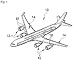
- an aircraft 10 comprises several engine assemblies 12 which are positioned under the wing 14 of the aircraft 10.
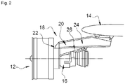
- An engine assembly 12 includes an engine 16, a nacelle (not shown in the figure 2 ) positioned around the engine 16 and a mast 18 which provides the link between the engine 16 and the rest of the aircraft 10, in particular the wing 14.
- the mast 18 comprises a primary structure 20 which is connected to the engine 16 by a front engine attachment 22, a rear engine attachment 24 and a couple of thrust rods 26 which ensure the resumption of the thrust forces.
- the front engine mount 22 includes an attachment body 28, connected to the mast 18, which has two yokes 30 arranged on either side of the mast 18, as well as two connecting rods 32 which each connect one of the yokes 30 of the attachment body 28 to a yoke 34 secured to the motor 16.
- Each connecting rod 32 is connected to one of the yokes 30 of the attachment body 28 by a first hinge pin 36 and to one of the yokes 34 of the motor 16 by a second hinge pin 38.
- the primary structure 20 has at the front two fixing lugs 40 which extend on either side of the primary structure 20 and which provide a contact face against which is pressed a contact face of the attachment body 28.
- the front engine mount 22 comprises a connection between the primary structure 20 and the body 28 having, for each fixing lug 40, several bolts 42 passing through the fixing lug 40 and the body 28 thus that at least one shear pin 44 which is housed astride a first hole in the fixing lug 40 and in a second hole in the attachment body 28. According to this document, during assembly, the pins shear are introduced from each fixing lug 40.
- each shear pin 44 In operation, each shear pin 44 must be immobilized in translation in the first and second holes.
- each shear pin 44 comprises, at a first end, a shoulder which bears against one of the fixing lugs 40.
- a removable stop is put in place at the second end of the shear pin 44.
- This embodiment requires the presence of a first clearance on the side of the fixing lug 40, in line with the first hole, to allow the introduction of the shear pin 44, and a second clearance on the side of the attachment body 28, to the right of the second hole, to allow the establishment of the removable stop.
- UHBR type for Ultra High By Pass Ratio in English
- the present invention aims to remedy all or part of the drawbacks of the prior art.
- the subject of the invention is an aircraft engine mount as claimed in claim 1.
- each shear pin and its immobilization systems from only the primary structure.
- the spacing between the attachment body and the aircraft engine can be greatly reduced in front of the attachment body.
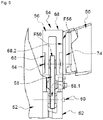
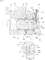
- a primary structure 50 of an aircraft mast is connected to an aircraft engine 52 by a front engine mount 54.
- a longitudinal direction is a direction parallel to the axis of rotation of the aircraft engine 52.
- a vertical longitudinal plane is a vertical plane passing through the axis of rotation of the aircraft engine 52.
- front and rear refer to the direction of flow of the air flow inside the aircraft engine 52 in operation, the air flow flowing from the front to the rear.
- horizontal and vertical correspond to the horizontal (perpendicular to the direction of gravity) and vertical (parallel to the direction of gravity) directions when the aircraft is on the ground.
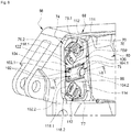
- the front engine mount 54 comprises an attachment body 56, two connecting rods 58, arranged on either side of the vertical longitudinal plane, each connecting the attachment body 56 to the aircraft engine 52 thus that for each connecting rod 58, a first articulation axis 60 connecting a first end 58.1 of the connecting rod 58 to a first yoke 62 of the aircraft engine 52 and at least one second articulation axis 64 connecting a second end 58.2 of the connecting rod 58 to a first yoke 66 of the attachment body 56.
- the primary structure 50 comprises at least a first contact face F50 against which is pressed at least a second contact face F56 of the attachment body 56.
- the first and second contact faces F50 and F56 are arranged in vertical planes approximately perpendicular to the longitudinal direction.
- the front engine mount 54 comprises an attachment body connection 68 connecting the attachment body 56 and a part of the primary structure 50, making it possible to maintain the first and second contact faces F50 and F56 pressed one against the other the other.
- This connection of the attachment body 68 comprises several connection elements 70, such as bolts for example, and at least one shear pin 72.
- the part of the primary structure 50 may be an insert on the primary structure 50.
- the primary structure 50 comprises two fixing lugs 74 having coplanar faces which form the first contact face F50 and which extend in a substantially vertical plane perpendicular to the longitudinal direction, on either side of the primary structure 50
- the attachment body connection 68 comprises two connection elements 70, 70 ′ and a shear pin 72, the connection elements 70, 70 ′ being arranged above and below the shear pin 72.
- each connecting element 70, 70 ′ is a bolt which comprises a head 76 having a circular lower section 76.1 and a polygonal upper section 76.2.
- the attachment body 56, the connecting rods 58, the first and second articulation axes 60, 64, the connecting elements 70, 70 ′ are not described any more because they may be identical to those of the prior art.
- Each shear pin 72 comprises a cylindrical body 78 which has a first end 78.1 called free, preferably rounded and a second end 78.2 (opposite the first end) as well as a flange 80 positioned at the second end 78.2 of the body cylindrical 78.
- the flange 80 has two flat faces perpendicular to the axis of the cylindrical body 78 and a diameter D80 greater than the diameter D78 of the cylindrical body 78.
- the primary structure 50 includes a first through hole 82, having a first end opening at the first contact face F50 and a second end opening at an access face F50 '.
- the attachment body 56 includes a second through hole 84, the first and second holes 82 and 84 being configured to accommodate the cylindrical body 78 of the shear pin 72.
- the first and second holes 82, 84 have a diameter substantially identical (apart from the assembly clearance) to the diameter D78 of the cylindrical body 78 of the shear pin 72.
- a first sliding ring 86 is interposed between the first hole 82 and the cylindrical body 78 and / or a second sliding ring 88 is interposed between the second hole 84 and the cylindrical body 78.
- the attachment body connection 68 comprises a system for immobilizing in translation the cylindrical body 78 of the shear pin 72 straddling the first and second holes 82, 84.
- the immobilization system in translation comprises a shoulder 90 near the second end of the first hole 82 which forms a bearing surface against which one of the faces of the flange 80 is supported in operation.
- This shoulder 90 is substantially perpendicular to the axis of the first hole.
- the first hole 82 comprises a main section 82.1 which extends from the contact face F50 to the shoulder 90 and an enlarged section 82.2 which extends from the shoulder 90 to the face d 'access F50'.
- the enlarged section 82.2 has a diameter greater than that of the main section 82.1 and the diameter D80 of the flange 80 so that the latter is housed in the enlarged section 82.2 and bears against the shoulder 90 in operation.
- the immobilization system in translation also comprises a removable stop 92, integral with the first structure 50, configured to immobilize the flange 80 between the shoulder 90 and the removable stop 92.
- the removable stop 92 is separated from the shoulder 90 d 'A distance substantially equal to the thickness of the flange 80 (dimension taken parallel to the axis of the cylindrical body 78 of the shear pin 72).
- the flange 80 is immobilized between the shoulder 90 and the removable stop 92.
- the shear pin 72 is immobilized in translation in the first and second holes 82, 84.
- the shoulder 90 and the removable stop 92 form a first immobilization system in translation.
- the enlarged section 82.2 comprises a groove 94 which extends between two planes perpendicular to the axis of the first hole 82 and over the entire circumference of the first hole 82.
- This groove 94 is separated from the shoulder 90 a distance substantially equal to the thickness of the flange 80.
- the removable stop 92 is a circlip 92.1 which is housed in the groove 94.
- the attachment body connection 68 comprises a second system for immobilizing in translation the shear pin 72.
- This second system for immobilizing in translation comprises on the one hand a groove 96 positioned in an extension 98 of the shear pin 72 and , on the other hand, a fork 100, connected directly or indirectly to the primary structure by at least one removable link 102, which cooperates with the groove 96 so as to immobilize in translation the shear pin 72.
- the extension 98 has a cylindrical shape coaxial with the cylindrical body 78.
- the extension 98, the flange 80 and the cylindrical body 78 form only one single piece.
- the extension 98 extends from the collar 80 to a free end 98.1.
- the extension 98 has a length L98 (distance between the flange 80 and the free end 98.1) greater than the length of the widened section L82.2 of the first hole 82 so that part of the extension 98, at the level of which is provided the groove 96, is located outside the first hole 82 when the flange 80 is in abutment against the shoulder 90 in operation.
- the groove 96 extends over the entire circumference of the extension 98 and has two sides positioned in two planes perpendicular to the axis of the cylindrical body 78.
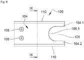
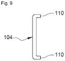
- the fork 100 is a stop plate 104 which has two branches 104.1 and 104.2 configured to be partially housed in the groove 96 of the extension 98 on either side of this denier.
- the stop plate 104 has a thickness substantially equal to the width of the groove 96 of the extension 98.
- the branches 104.1 and 104.2 are separated by a distance substantially equal to the diameter of the bottom of the groove 96.
- the branches 104.1 and 104.2 are separated by a U-shaped cutout 106 comprising a base 106.1 which describes a semicircle of diameter substantially equal to that of the bottom of the groove 96.
- This stop plate 104 also includes a through hole 108 for each removable link 102 .
- the stop plate 104 has a rectangular shape and comprises, at the level of a first small side, the U-shaped cutout 106 which delimits the two branches 104.1 and 104.2 and, near the second short side, the (or) orifice (s) passing through 108 provided for the removable connection 102.
- the stop plate 104 includes curved edges 110 at the two long sides.
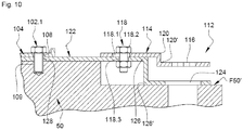
- the removable link 102 comprises two fixing elements 102.1, 102.2, such as screws for example, which pass through the stop plate 104 via the through holes 108 and are screwed into tapped holes 109 (visible on the figure 10 ) arranged in the primary structure 50.
- the attachment body connection 68 comprises at least one anti-rotation system 112 for at least one of the connection elements 70, 70 '.
- the attachment body connection 68 comprises an anti-rotation system 112 for each connection element 70, 70 '.
- an anti-rotation system 112 comprises an anti-rotation plate 114 which has a through orifice 116 which has a section complementary to the upper section 76.2 of the head 76 of the connecting element 70, 70 ′ as well that a removable link 118 to connect it directly or indirectly to the primary structure 50.
- complementary it is meant that when the upper section 76.2 of the head 76 is inserted into the through hole 116, the anti-rotation plate 114 and the head 76 are immobilized in rotation relative to each other.
- the anti-rotation plate 114 may include fold lines 120, 120 ′ in order to adapt to the relief of the access face F50 ′.
- the removable link 118 comprises a first through hole 118.1 of oblong shape at the level of the anti-rotation plate 114 and a fixing element 118.2, such as a screw or a bolt for example.
- the oblong shape of the passage hole 118.1 has the same center as the through hole 116 and makes it possible to house the fixing element 118.2 while tolerating a slight angular movement of the anti-rotation plate 114.
- the attachment body link 68 comprises, for each fixing lug 74, a support plate 122, to which the stop plate 104 and the anti-rotation plate or plates 114 are connected, which is itself connected to the primary structure 50.
- This support plate 122 comprises a passage orifice 124, for each connecting element 70, 70 ', which has a section approximately equal to the lower section 76.1 of the head 76 of the corresponding connecting element 70, 70'.
- This support plate 122 may include fold lines 126, 126 'in order to adapt to the relief of the access face F50'. It has, for each anti-rotation plate 114, a second passage hole 118.3 configured to be traversed by the fixing element 118.2 of the removable connection 118 of the anti-rotation plate 114. This second passage hole 118.3 has a section circular with a diameter slightly larger than that of the fixing element 118.2.
- the support plate 122 also has through holes 128 for each fixing element 102.1, 102.2 of the stop plate 114.
- the method of mounting the engine mount 54 is as follows:
- the attachment body 56 is connected to the aircraft engine 52 by the connecting rods 58.
- the aircraft engine 52 is moved vertically so as to position the first and second contact faces F50 and F56 one opposite the other.
- the through holes of the connecting elements 70, 70 ′ are aligned for example by inserting centering pins in the first and second holes 82, 84 intended for the shear pins.
- the support plate 122 is put in place by making the passage orifices 124 cooperate with the lower section 76.2 of the head 76 of each connecting element 70, 70 '.
- the stop plate 104 is put in place by making the branches 104.1, 104.2 cooperate with the groove 96 of the extension 98 of the shear pin 72.
- the fixing elements 102.1, 102.2 are put in place so as to secure the support plate 122 and stop plate 104 at the primary structure 50.
- each connecting element 70, 70 ′ the anti-rotation plate 114 is fitted onto the upper section 76.2 of the head 76 and connected to the support plate 122 by means of the fixing element 118.2.
- each shear pin 72 and its immobilization systems are put in place from only the access face F50 '.
- the spacing between the attachment body 56 and the aircraft engine 52 can be very reduced at the front of the attachment body 56.
Landscapes
- Engineering & Computer Science (AREA)
- Aviation & Aerospace Engineering (AREA)
- Manufacturing & Machinery (AREA)
- Transportation (AREA)
- Connection Of Plates (AREA)
Applications Claiming Priority (1)
| Application Number | Priority Date | Filing Date | Title |
|---|---|---|---|
| FR1900211A FR3091519A1 (fr) | 2019-01-09 | 2019-01-09 | Attache-moteur d’aéronef comprenant au moins un système d’immobilisation en translation de type fourchette d’un pion de cisaillement, procédé de montage de ladite attache-moteur et aéronef comprenant ladite attache-moteur |
Publications (2)
| Publication Number | Publication Date |
|---|---|
| EP3680175A1 true EP3680175A1 (de) | 2020-07-15 |
| EP3680175B1 EP3680175B1 (de) | 2021-02-24 |
Family
ID=67107639
Family Applications (1)
| Application Number | Title | Priority Date | Filing Date |
|---|---|---|---|
| EP20150299.4A Active EP3680175B1 (de) | 2019-01-09 | 2020-01-06 | Antriebsaufhängung beinhaltend zumindest ein joch-befestigungssystem für einen scherstift, montageverfahren für einer solchen aufhängung und flugzeug beinhaltend eine solche aufhängung |
Country Status (4)
| Country | Link |
|---|---|
| US (1) | US11434015B2 (de) |
| EP (1) | EP3680175B1 (de) |
| CN (1) | CN111422366B (de) |
| FR (1) | FR3091519A1 (de) |
Families Citing this family (3)
| Publication number | Priority date | Publication date | Assignee | Title |
|---|---|---|---|---|
| US11639669B2 (en) | 2021-02-08 | 2023-05-02 | General Electric Company | Systems and methods for selectively disconnecting embedded electrical machines in gas turbine engines |
| FR3124491A1 (fr) * | 2021-06-29 | 2022-12-30 | Airbus Operations (S.A.S.) | Ensemble propulseur d’aéronef comprenant une attache moteur avant comportant une poutre transversale partiellement positionnée face à un renfort transversal avant d’une structure primaire d’un mât |
| FR3126695A1 (fr) * | 2021-09-03 | 2023-03-10 | Airbus Operations | Système d’attache moteur avant pour un moteur d’aéronef qui comporte une structure compacte |
Citations (4)
| Publication number | Priority date | Publication date | Assignee | Title |
|---|---|---|---|---|
| US4943013A (en) * | 1988-09-01 | 1990-07-24 | Societe Nationale D'etude Et De Construction De Moteurs D-Aviation (Snecma) | Fastener system for a jet engine mounting |
| US5649417A (en) * | 1995-03-24 | 1997-07-22 | The Boeing Company | Fail-safe engine mount system |
| FR2891245A1 (fr) | 2005-09-26 | 2007-03-30 | Airbus France Sas | Procede de montage d'un moteur d'aeronef sur une structure rigide d'un mat d'accrochage du moteur |
| FR2891254A1 (fr) | 2005-09-29 | 2007-03-30 | Airbus France Sas | Ensemble moteur pour aeronef |
Family Cites Families (16)
| Publication number | Priority date | Publication date | Assignee | Title |
|---|---|---|---|---|
| US4603822A (en) * | 1983-12-08 | 1986-08-05 | The Boeing Company | Aft engine mount |
| EP1625308A2 (de) * | 2003-05-16 | 2006-02-15 | Shur-Lok Corporation | Sperrklinkenstift mit massivem schaft und redundantem verriegelungssystem |
| FR2878229B1 (fr) * | 2004-11-23 | 2008-04-18 | Airbus France Sas | Systeme de fixation d'un mat de moteur a l'aile d'un aeronef |
| FR2883839B1 (fr) * | 2005-03-29 | 2007-06-29 | Snecma Moteurs Sa | Suspension arriere de turboreacteur |
| FR2891243B1 (fr) * | 2005-09-26 | 2009-04-03 | Airbus France Sas | Mat d'accrochage de moteur pour aeronef |
| FR2923459B1 (fr) * | 2007-11-09 | 2010-05-21 | Snecma | Moyen de blocage en rotation d'un axe supportant un organe de suspension de turbomoteur |
| FR2974065B1 (fr) * | 2011-04-14 | 2013-05-10 | Snecma | Procede de montage d'un moteur d'aeronef sur un pylone et attache moteur pour la mise en oeuvre d'un tel procede. |
| DE102011075919A1 (de) * | 2011-05-16 | 2012-11-22 | Siemens Aktiengesellschaft | Vorrichtung zum Fixieren von Verbindungsmitteln |
| US8851417B2 (en) * | 2012-08-07 | 2014-10-07 | United Technologies Corporation | Self-retaining shear pin for blind mount location |
| US9248921B2 (en) * | 2013-07-11 | 2016-02-02 | Spirit Aerosystems, Inc. | Method for mounting a pylon to an aircraft |
| EP3024729B1 (de) * | 2013-07-26 | 2022-04-27 | MRA Systems, LLC | Triebwerkspylon für luftfahrzeug |
| FR3014972B1 (fr) * | 2013-12-12 | 2016-04-22 | Airbus Operations Sas | Assemblage comprenant un axe d'articulation supporte par une chape et immobilise en translation par un dispositif de blocage integrant un double systeme d'anti-rotation |
| FR3014973B1 (fr) * | 2013-12-12 | 2016-01-22 | Airbus Operations Sas | Assemblage comprenant un axe d'articulation supporte par une chape et immobilise en translation par un dispositif de blocage integrant un double systeme d'anti-rotation |
| FR3014970B1 (fr) * | 2013-12-12 | 2016-01-22 | Airbus Operations Sas | Assemblage comprenant un axe d'articulation supporte par une chape et immobilise en translation par un dispositif de blocage integrant un double systeme d'anti-rotation |
| FR3061480B1 (fr) * | 2016-12-30 | 2019-05-31 | Airbus Operations | Ensemble moteur pour aeronef comprenant une attache moteur avant facilitant son montage |
| FR3088902B1 (fr) * | 2018-11-27 | 2020-11-06 | Safran Aircraft Engines | Assemblage pour ensemble moteur d’aéronef, comprenant une fonction anti-rotation améliorée |
-
2019
- 2019-01-09 FR FR1900211A patent/FR3091519A1/fr not_active Ceased
-
2020
- 2020-01-03 US US16/733,691 patent/US11434015B2/en active Active
- 2020-01-06 EP EP20150299.4A patent/EP3680175B1/de active Active
- 2020-01-07 CN CN202010014109.6A patent/CN111422366B/zh active Active
Patent Citations (4)
| Publication number | Priority date | Publication date | Assignee | Title |
|---|---|---|---|---|
| US4943013A (en) * | 1988-09-01 | 1990-07-24 | Societe Nationale D'etude Et De Construction De Moteurs D-Aviation (Snecma) | Fastener system for a jet engine mounting |
| US5649417A (en) * | 1995-03-24 | 1997-07-22 | The Boeing Company | Fail-safe engine mount system |
| FR2891245A1 (fr) | 2005-09-26 | 2007-03-30 | Airbus France Sas | Procede de montage d'un moteur d'aeronef sur une structure rigide d'un mat d'accrochage du moteur |
| FR2891254A1 (fr) | 2005-09-29 | 2007-03-30 | Airbus France Sas | Ensemble moteur pour aeronef |
Also Published As
| Publication number | Publication date |
|---|---|
| US11434015B2 (en) | 2022-09-06 |
| EP3680175B1 (de) | 2021-02-24 |
| CN111422366B (zh) | 2023-04-14 |
| CN111422366A (zh) | 2020-07-17 |
| US20200216184A1 (en) | 2020-07-09 |
| FR3091519A1 (fr) | 2020-07-10 |
Similar Documents
| Publication | Publication Date | Title |
|---|---|---|
| FR3014970A1 (fr) | Assemblage comprenant un axe d'articulation supporte par une chape et immobilise en translation par un dispositif de blocage integrant un double systeme d'anti-rotation | |
| EP2139768B1 (de) | Flugzeugmotorbefestigungspylon mit einer mit einer tonnenmutter versehenen hinteren motorbefestigung | |
| EP1858758B1 (de) | Motorbefestigung eines zwischen einer befestigungsstrebe und einem flugzeugtriebwerk angebrachten montagesystems | |
| EP3680175B1 (de) | Antriebsaufhängung beinhaltend zumindest ein joch-befestigungssystem für einen scherstift, montageverfahren für einer solchen aufhängung und flugzeug beinhaltend eine solche aufhängung | |
| EP3626624B1 (de) | Montageverfahren von einem pylon eines flugzeugs | |
| EP4484297B1 (de) | Vordermotorbefestigungssystem für einen flugzeugmotor mit kompakter struktur | |
| EP4484298B1 (de) | Vordermotorbefestigungssystem für einen flugzeugmotor mit kompakter struktur | |
| EP3483069A1 (de) | Luftfahrezugtriebwerksbefestigungssystem | |
| WO2013128123A1 (fr) | Procede pour maintenir une piece d'adaptation sur un carter tubulaire d'un turbomoteur, piece d'adaptation et systeme de maintien correspondants | |
| FR3113484A1 (fr) | Ensemble propulseur d’aéronef comprenant des bielles d’une attache moteur avant reliées directement à un renfort transversal avant d’une structure primaire d’un mât d’aéronef | |
| FR3073824A1 (fr) | Ensemble pour aeronef comprenant une structure primaire de mat d'accrochage fixee a un caisson de voilure par des attaches partiellement enterrees dans la structure primaire | |
| FR3058986A1 (fr) | Attache arriere d'un moteur d'aeronef comportant des temoins de rupture | |
| FR3104219A1 (fr) | Assemblage comprenant un axe de liaison immobile en translation et en rotation, attache-moteur ou aéronef comprenant un tel assemblage | |
| FR3156756A1 (fr) | Ensemble propulsif pour aéronef comportant un moteur, un mât et des moyens d’accrochage du moteur au mât | |
| FR3122164A1 (fr) | Dispositif de liaison reliant un moteur d’aéronef et une structure primaire d’un mât d’aéronef comprenant un palonnier ainsi qu’un système de limitation du débattement du palonnier intégrant une double butée, aéronef comprenant un tel dispositif de liaison | |
| CA2812373A1 (fr) | Ensemble d'accrochage d'une suspension d'un ensemble propulsif d'aeronef | |
| FR3149869A1 (fr) | Dispositif pour coupler un système de propulsion à un mât reacteur d’un aeronef et aeronef correspondant | |
| EP3680176B1 (de) | Antriebsaufhängung beinhaltend zumindest ein blindplattefixierungssystem für einen scherstift, montageverfahren einer solchen aufhängung und flugzeug beinhaltend eine solche aufhängung | |
| FR3096346A1 (fr) | Aéronef comprenant deux attaches voilures avant comportant chacune au moins un élément de liaison vertical | |
| FR3135450A1 (fr) | Assemblage d’un mât réacteur avec une aile d’un aeronef. | |
| EP3792182B1 (de) | Flugzeugtriebwerksanordnung mit einer schubkraftaufnahmevorrichtung | |
| FR2971980A1 (fr) | Vehicule comportant un absorbeur de choc et absorbeur de choc correspondant | |
| EP4570647A1 (de) | Vorrichtung zur absorption von energie durch kompression, luftfahrzeug, das mindestens eine solche vorrichtung umfasst | |
| FR2887522A1 (fr) | Ensemble pour aeronef comprenant un element de voilure ainsi qu'un mat d'accrochage | |
| EP3728039B1 (de) | Aufhängevorrichtung |
Legal Events
| Date | Code | Title | Description |
|---|---|---|---|
| PUAI | Public reference made under article 153(3) epc to a published international application that has entered the european phase |
Free format text: ORIGINAL CODE: 0009012 |
|
| STAA | Information on the status of an ep patent application or granted ep patent |
Free format text: STATUS: REQUEST FOR EXAMINATION WAS MADE |
|
| 17P | Request for examination filed |
Effective date: 20200107 |
|
| AK | Designated contracting states |
Kind code of ref document: A1 Designated state(s): AL AT BE BG CH CY CZ DE DK EE ES FI FR GB GR HR HU IE IS IT LI LT LU LV MC MK MT NL NO PL PT RO RS SE SI SK SM TR |
|
| AX | Request for extension of the european patent |
Extension state: BA ME |
|
| GRAP | Despatch of communication of intention to grant a patent |
Free format text: ORIGINAL CODE: EPIDOSNIGR1 |
|
| STAA | Information on the status of an ep patent application or granted ep patent |
Free format text: STATUS: GRANT OF PATENT IS INTENDED |
|
| RIC1 | Information provided on ipc code assigned before grant |
Ipc: B64D 27/26 20060101AFI20200812BHEP |
|
| INTG | Intention to grant announced |
Effective date: 20200916 |
|
| GRAS | Grant fee paid |
Free format text: ORIGINAL CODE: EPIDOSNIGR3 |
|
| GRAA | (expected) grant |
Free format text: ORIGINAL CODE: 0009210 |
|
| STAA | Information on the status of an ep patent application or granted ep patent |
Free format text: STATUS: THE PATENT HAS BEEN GRANTED |
|
| AK | Designated contracting states |
Kind code of ref document: B1 Designated state(s): AL AT BE BG CH CY CZ DE DK EE ES FI FR GB GR HR HU IE IS IT LI LT LU LV MC MK MT NL NO PL PT RO RS SE SI SK SM TR |
|
| RBV | Designated contracting states (corrected) |
Designated state(s): AL AT BE BG CH CY CZ DE DK EE ES FI FR GB GR HR HU IE IS IT LI LT LU LV MC MK MT NL NO PL PT RO RS SE SI SK SM TR |
|
| REG | Reference to a national code |
Ref country code: CH Ref legal event code: EP |
|
| REG | Reference to a national code |
Ref country code: DE Ref legal event code: R096 Ref document number: 602020000008 Country of ref document: DE |
|
| REG | Reference to a national code |
Ref country code: AT Ref legal event code: REF Ref document number: 1364148 Country of ref document: AT Kind code of ref document: T Effective date: 20210315 |
|
| REG | Reference to a national code |
Ref country code: IE Ref legal event code: FG4D Free format text: LANGUAGE OF EP DOCUMENT: FRENCH |
|
| REG | Reference to a national code |
Ref country code: LT Ref legal event code: MG9D |
|
| REG | Reference to a national code |
Ref country code: NL Ref legal event code: MP Effective date: 20210224 |
|
| PG25 | Lapsed in a contracting state [announced via postgrant information from national office to epo] |
Ref country code: BG Free format text: LAPSE BECAUSE OF FAILURE TO SUBMIT A TRANSLATION OF THE DESCRIPTION OR TO PAY THE FEE WITHIN THE PRESCRIBED TIME-LIMIT Effective date: 20210524 Ref country code: HR Free format text: LAPSE BECAUSE OF FAILURE TO SUBMIT A TRANSLATION OF THE DESCRIPTION OR TO PAY THE FEE WITHIN THE PRESCRIBED TIME-LIMIT Effective date: 20210224 Ref country code: GR Free format text: LAPSE BECAUSE OF FAILURE TO SUBMIT A TRANSLATION OF THE DESCRIPTION OR TO PAY THE FEE WITHIN THE PRESCRIBED TIME-LIMIT Effective date: 20210525 Ref country code: FI Free format text: LAPSE BECAUSE OF FAILURE TO SUBMIT A TRANSLATION OF THE DESCRIPTION OR TO PAY THE FEE WITHIN THE PRESCRIBED TIME-LIMIT Effective date: 20210224 Ref country code: NO Free format text: LAPSE BECAUSE OF FAILURE TO SUBMIT A TRANSLATION OF THE DESCRIPTION OR TO PAY THE FEE WITHIN THE PRESCRIBED TIME-LIMIT Effective date: 20210524 Ref country code: PT Free format text: LAPSE BECAUSE OF FAILURE TO SUBMIT A TRANSLATION OF THE DESCRIPTION OR TO PAY THE FEE WITHIN THE PRESCRIBED TIME-LIMIT Effective date: 20210624 Ref country code: LT Free format text: LAPSE BECAUSE OF FAILURE TO SUBMIT A TRANSLATION OF THE DESCRIPTION OR TO PAY THE FEE WITHIN THE PRESCRIBED TIME-LIMIT Effective date: 20210224 |
|
| REG | Reference to a national code |
Ref country code: AT Ref legal event code: MK05 Ref document number: 1364148 Country of ref document: AT Kind code of ref document: T Effective date: 20210224 |
|
| PG25 | Lapsed in a contracting state [announced via postgrant information from national office to epo] |
Ref country code: RS Free format text: LAPSE BECAUSE OF FAILURE TO SUBMIT A TRANSLATION OF THE DESCRIPTION OR TO PAY THE FEE WITHIN THE PRESCRIBED TIME-LIMIT Effective date: 20210224 Ref country code: SE Free format text: LAPSE BECAUSE OF FAILURE TO SUBMIT A TRANSLATION OF THE DESCRIPTION OR TO PAY THE FEE WITHIN THE PRESCRIBED TIME-LIMIT Effective date: 20210224 Ref country code: PL Free format text: LAPSE BECAUSE OF FAILURE TO SUBMIT A TRANSLATION OF THE DESCRIPTION OR TO PAY THE FEE WITHIN THE PRESCRIBED TIME-LIMIT Effective date: 20210224 Ref country code: NL Free format text: LAPSE BECAUSE OF FAILURE TO SUBMIT A TRANSLATION OF THE DESCRIPTION OR TO PAY THE FEE WITHIN THE PRESCRIBED TIME-LIMIT Effective date: 20210224 Ref country code: LV Free format text: LAPSE BECAUSE OF FAILURE TO SUBMIT A TRANSLATION OF THE DESCRIPTION OR TO PAY THE FEE WITHIN THE PRESCRIBED TIME-LIMIT Effective date: 20210224 |
|
| PG25 | Lapsed in a contracting state [announced via postgrant information from national office to epo] |
Ref country code: IS Free format text: LAPSE BECAUSE OF FAILURE TO SUBMIT A TRANSLATION OF THE DESCRIPTION OR TO PAY THE FEE WITHIN THE PRESCRIBED TIME-LIMIT Effective date: 20210624 |
|
| PG25 | Lapsed in a contracting state [announced via postgrant information from national office to epo] |
Ref country code: EE Free format text: LAPSE BECAUSE OF FAILURE TO SUBMIT A TRANSLATION OF THE DESCRIPTION OR TO PAY THE FEE WITHIN THE PRESCRIBED TIME-LIMIT Effective date: 20210224 Ref country code: CZ Free format text: LAPSE BECAUSE OF FAILURE TO SUBMIT A TRANSLATION OF THE DESCRIPTION OR TO PAY THE FEE WITHIN THE PRESCRIBED TIME-LIMIT Effective date: 20210224 Ref country code: AT Free format text: LAPSE BECAUSE OF FAILURE TO SUBMIT A TRANSLATION OF THE DESCRIPTION OR TO PAY THE FEE WITHIN THE PRESCRIBED TIME-LIMIT Effective date: 20210224 Ref country code: SM Free format text: LAPSE BECAUSE OF FAILURE TO SUBMIT A TRANSLATION OF THE DESCRIPTION OR TO PAY THE FEE WITHIN THE PRESCRIBED TIME-LIMIT Effective date: 20210224 |
|
| REG | Reference to a national code |
Ref country code: DE Ref legal event code: R097 Ref document number: 602020000008 Country of ref document: DE |
|
| PG25 | Lapsed in a contracting state [announced via postgrant information from national office to epo] |
Ref country code: DK Free format text: LAPSE BECAUSE OF FAILURE TO SUBMIT A TRANSLATION OF THE DESCRIPTION OR TO PAY THE FEE WITHIN THE PRESCRIBED TIME-LIMIT Effective date: 20210224 Ref country code: RO Free format text: LAPSE BECAUSE OF FAILURE TO SUBMIT A TRANSLATION OF THE DESCRIPTION OR TO PAY THE FEE WITHIN THE PRESCRIBED TIME-LIMIT Effective date: 20210224 Ref country code: SK Free format text: LAPSE BECAUSE OF FAILURE TO SUBMIT A TRANSLATION OF THE DESCRIPTION OR TO PAY THE FEE WITHIN THE PRESCRIBED TIME-LIMIT Effective date: 20210224 |
|
| PLBE | No opposition filed within time limit |
Free format text: ORIGINAL CODE: 0009261 |
|
| STAA | Information on the status of an ep patent application or granted ep patent |
Free format text: STATUS: NO OPPOSITION FILED WITHIN TIME LIMIT |
|
| PG25 | Lapsed in a contracting state [announced via postgrant information from national office to epo] |
Ref country code: ES Free format text: LAPSE BECAUSE OF FAILURE TO SUBMIT A TRANSLATION OF THE DESCRIPTION OR TO PAY THE FEE WITHIN THE PRESCRIBED TIME-LIMIT Effective date: 20210224 Ref country code: AL Free format text: LAPSE BECAUSE OF FAILURE TO SUBMIT A TRANSLATION OF THE DESCRIPTION OR TO PAY THE FEE WITHIN THE PRESCRIBED TIME-LIMIT Effective date: 20210224 |
|
| 26N | No opposition filed |
Effective date: 20211125 |
|
| PG25 | Lapsed in a contracting state [announced via postgrant information from national office to epo] |
Ref country code: IT Free format text: LAPSE BECAUSE OF FAILURE TO SUBMIT A TRANSLATION OF THE DESCRIPTION OR TO PAY THE FEE WITHIN THE PRESCRIBED TIME-LIMIT Effective date: 20210224 |
|
| PG25 | Lapsed in a contracting state [announced via postgrant information from national office to epo] |
Ref country code: IS Free format text: LAPSE BECAUSE OF FAILURE TO SUBMIT A TRANSLATION OF THE DESCRIPTION OR TO PAY THE FEE WITHIN THE PRESCRIBED TIME-LIMIT Effective date: 20210624 |
|
| PG25 | Lapsed in a contracting state [announced via postgrant information from national office to epo] |
Ref country code: MC Free format text: LAPSE BECAUSE OF FAILURE TO SUBMIT A TRANSLATION OF THE DESCRIPTION OR TO PAY THE FEE WITHIN THE PRESCRIBED TIME-LIMIT Effective date: 20210224 |
|
| REG | Reference to a national code |
Ref country code: BE Ref legal event code: MM Effective date: 20220131 |
|
| PG25 | Lapsed in a contracting state [announced via postgrant information from national office to epo] |
Ref country code: LU Free format text: LAPSE BECAUSE OF NON-PAYMENT OF DUE FEES Effective date: 20220106 |
|
| PG25 | Lapsed in a contracting state [announced via postgrant information from national office to epo] |
Ref country code: BE Free format text: LAPSE BECAUSE OF NON-PAYMENT OF DUE FEES Effective date: 20220131 |
|
| PG25 | Lapsed in a contracting state [announced via postgrant information from national office to epo] |
Ref country code: IE Free format text: LAPSE BECAUSE OF NON-PAYMENT OF DUE FEES Effective date: 20220106 |
|
| REG | Reference to a national code |
Ref country code: CH Ref legal event code: PL |
|
| PG25 | Lapsed in a contracting state [announced via postgrant information from national office to epo] |
Ref country code: LI Free format text: LAPSE BECAUSE OF NON-PAYMENT OF DUE FEES Effective date: 20230131 Ref country code: CH Free format text: LAPSE BECAUSE OF NON-PAYMENT OF DUE FEES Effective date: 20230131 |
|
| REG | Reference to a national code |
Ref country code: DE Ref legal event code: R079 Ref document number: 602020000008 Country of ref document: DE Free format text: PREVIOUS MAIN CLASS: B64D0027260000 Ipc: B64D0027400000 |
|
| PG25 | Lapsed in a contracting state [announced via postgrant information from national office to epo] |
Ref country code: MK Free format text: LAPSE BECAUSE OF FAILURE TO SUBMIT A TRANSLATION OF THE DESCRIPTION OR TO PAY THE FEE WITHIN THE PRESCRIBED TIME-LIMIT Effective date: 20210224 Ref country code: CY Free format text: LAPSE BECAUSE OF FAILURE TO SUBMIT A TRANSLATION OF THE DESCRIPTION OR TO PAY THE FEE WITHIN THE PRESCRIBED TIME-LIMIT Effective date: 20210224 |
|
| PG25 | Lapsed in a contracting state [announced via postgrant information from national office to epo] |
Ref country code: HU Free format text: LAPSE BECAUSE OF FAILURE TO SUBMIT A TRANSLATION OF THE DESCRIPTION OR TO PAY THE FEE WITHIN THE PRESCRIBED TIME-LIMIT; INVALID AB INITIO Effective date: 20200106 |
|
| PG25 | Lapsed in a contracting state [announced via postgrant information from national office to epo] |
Ref country code: MT Free format text: LAPSE BECAUSE OF FAILURE TO SUBMIT A TRANSLATION OF THE DESCRIPTION OR TO PAY THE FEE WITHIN THE PRESCRIBED TIME-LIMIT Effective date: 20210224 |
|
| PG25 | Lapsed in a contracting state [announced via postgrant information from national office to epo] |
Ref country code: TR Free format text: LAPSE BECAUSE OF FAILURE TO SUBMIT A TRANSLATION OF THE DESCRIPTION OR TO PAY THE FEE WITHIN THE PRESCRIBED TIME-LIMIT Effective date: 20210224 |
|
| PG25 | Lapsed in a contracting state [announced via postgrant information from national office to epo] |
Ref country code: SI Free format text: LAPSE BECAUSE OF FAILURE TO SUBMIT A TRANSLATION OF THE DESCRIPTION OR TO PAY THE FEE WITHIN THE PRESCRIBED TIME-LIMIT Effective date: 20210224 |
|
| PGFP | Annual fee paid to national office [announced via postgrant information from national office to epo] |
Ref country code: GB Payment date: 20260123 Year of fee payment: 7 |
|
| PGFP | Annual fee paid to national office [announced via postgrant information from national office to epo] |
Ref country code: DE Payment date: 20260121 Year of fee payment: 7 |
|
| PGFP | Annual fee paid to national office [announced via postgrant information from national office to epo] |
Ref country code: FR Payment date: 20260123 Year of fee payment: 7 |