EP3680320A1 - Dispositif de décharge pour un système de chargement permettant de fournir de la biomasse dans une installation de biogaz - Google Patents
Dispositif de décharge pour un système de chargement permettant de fournir de la biomasse dans une installation de biogaz Download PDFInfo
- Publication number
- EP3680320A1 EP3680320A1 EP19214447.5A EP19214447A EP3680320A1 EP 3680320 A1 EP3680320 A1 EP 3680320A1 EP 19214447 A EP19214447 A EP 19214447A EP 3680320 A1 EP3680320 A1 EP 3680320A1
- Authority
- EP
- European Patent Office
- Prior art keywords
- arm
- rotation
- discharge device
- discharge
- axis
- Prior art date
- Legal status (The legal status is an assumption and is not a legal conclusion. Google has not performed a legal analysis and makes no representation as to the accuracy of the status listed.)
- Granted
Links
Images

Classifications
-
- C—CHEMISTRY; METALLURGY
- C12—BIOCHEMISTRY; BEER; SPIRITS; WINE; VINEGAR; MICROBIOLOGY; ENZYMOLOGY; MUTATION OR GENETIC ENGINEERING
- C12M—APPARATUS FOR ENZYMOLOGY OR MICROBIOLOGY; APPARATUS FOR CULTURING MICROORGANISMS FOR PRODUCING BIOMASS, FOR GROWING CELLS OR FOR OBTAINING FERMENTATION OR METABOLIC PRODUCTS, i.e. BIOREACTORS OR FERMENTERS
- C12M21/00—Bioreactors or fermenters specially adapted for specific uses
- C12M21/04—Bioreactors or fermenters specially adapted for specific uses for producing gas, e.g. biogas
-
- C—CHEMISTRY; METALLURGY
- C12—BIOCHEMISTRY; BEER; SPIRITS; WINE; VINEGAR; MICROBIOLOGY; ENZYMOLOGY; MUTATION OR GENETIC ENGINEERING
- C12M—APPARATUS FOR ENZYMOLOGY OR MICROBIOLOGY; APPARATUS FOR CULTURING MICROORGANISMS FOR PRODUCING BIOMASS, FOR GROWING CELLS OR FOR OBTAINING FERMENTATION OR METABOLIC PRODUCTS, i.e. BIOREACTORS OR FERMENTERS
- C12M33/00—Means for introduction, transport, positioning, extraction, harvesting, peeling or sampling of biological material in or from the apparatus
-
- Y—GENERAL TAGGING OF NEW TECHNOLOGICAL DEVELOPMENTS; GENERAL TAGGING OF CROSS-SECTIONAL TECHNOLOGIES SPANNING OVER SEVERAL SECTIONS OF THE IPC; TECHNICAL SUBJECTS COVERED BY FORMER USPC CROSS-REFERENCE ART COLLECTIONS [XRACs] AND DIGESTS
- Y02—TECHNOLOGIES OR APPLICATIONS FOR MITIGATION OR ADAPTATION AGAINST CLIMATE CHANGE
- Y02E—REDUCTION OF GREENHOUSE GAS [GHG] EMISSIONS, RELATED TO ENERGY GENERATION, TRANSMISSION OR DISTRIBUTION
- Y02E50/00—Technologies for the production of fuel of non-fossil origin
- Y02E50/30—Fuel from waste, e.g. synthetic alcohol or diesel
Definitions
- the invention relates to a discharge device for a charging system for providing biomass in a biogas plant.
- the invention also relates to a charging system for charging a biogas plant with biomass.
- the discharge device according to the invention for a charging system which is designed for charging a biogas plant with biomass, comprises one Connection body with an interface for a drive device of the loading system, by means of which the discharge device can be set in rotation about an axis of rotation.
- the interface of the connection body can be, for example, a hub, a flange or the like, by means of which the connection body can be connected, for example, to a gear, which can be part of the said drive device of the loading system.
- the gear unit can be a planetary gear unit, for example, which can be connected to a motor, for example an electric motor, via a drive shaft or the like.
- the planetary gear, the drive shaft and the electric motor form the said drive device of the loading system, by means of which the discharge device can be set in rotation about the said axis of rotation.
- the discharge device is set in rotation about the said axis of rotation by means of the drive device, the at least one discharge arm which extends radially outwards is rotated about the axis of rotation.
- Biomass arranged in a container of the charging system can thus be conveyed to the said discharge opening of the charging system by means of the discharge device likewise arranged in the container of the charging system. Because the main arm of the discharge arm is rigidly connected to the connection body, this always follows the rotational movement of the connection body, which can be driven by means of the drive device.
- the arm extension arranged on the main arm bends away about the axis of rotation.
- the arm extension can be rotated about the axis of rotation, which extends parallel to the axis of rotation of the discharge device, if a correspondingly high moment or a correspondingly high force is exerted on the arm extension. This can be the case, for example, if the arm extension encounters large chunks of material in the biomass.
- the pivoting away of the arm extension prevents an excessive counter-torque from being exerted on the drive device, by means of which the discharge device is driven.
- a transmission of the drive device can be spared, which can ensure particularly smooth or low-failure operation.
- the arm extension arranged on the main arm is rotatably mounted on the main arm about the axis of rotation running parallel to the axis of rotation, the torque required that the drive device of the loading system must provide in order to set the discharge device in rotation about the axis of rotation can be limited to a certain extent become. If a corresponding amount of biomass has accumulated along the main direction of extension of the discharge arm, which is to be moved by appropriate rotation of the discharge device, the arm extension which is rotatably arranged on the main arm can buckle, as a result of which the torque to be applied for driving the discharge device about the axis of rotation to a specific torque value can be limited.
- the restoring element is a tension spring which is arranged at least indirectly on the main arm with a first longitudinal end and at least indirectly on the arm extension with a second longitudinal end. This results in the particular advantage that the arm extension can be rotated from its neutral position in two directions about the axis of rotation from the discharge device, regardless of the direction of rotation. If, for example, a direction of rotation of the drive device is reversed, the restoring element functions just as well as before, since it exerts the restoring moment on the arm extension in the direction of its neutral position regardless of the direction of rotation of the arm extension about the axis of rotation.
- the restoring element designed as a tension spring always counteracts a rotation of the arm extension about the axis of rotation relative to the main arm, starting from the neutral position.
- the respective longitudinal axes of the main arm, the arm extension and the restoring element designed as a tension spring are aligned with one another in the neutral position of the arm extension.
- a spring mechanism can generally be provided, e.g. in the form of a leaf spring, compression spring, a restoring element made of spring steel or the like.
- a further advantageous embodiment of the invention provides that the arm extension, starting from the neutral position, can be rotated through 90 ° about the axis of rotation relative to the main arm.
- the arm extension can preferably be rotated by 90 ° in two directions or orientations about the axis of rotation relative to the main arm.
- the discharge device can, for example, have respective stops which prevent the arm extension from rotating beyond 90 °, starting from the neutral position. Because the arm extension can be rotated from the neutral position by 90 ° about the axis of rotation relative to the main arm, the arm extension can be aligned at least substantially tangentially to the circular path that describes a tip of the main arm when the drive device in the discharge device about the axis of rotation Rotation offset.
- the arm extension When the arm extension is folded down by 90 ° relative to the main arm, the arm extension sets Rotational movement or rotational movement of the discharge device at least practically no longer offers any resistance, since biomass previously accumulated on the arm extension can then slide along the folded arm extension in accordance with the rotation of the discharge device.
- the main arm has a cavity closed by means of a housing, in which a bearing area of the arm extension is arranged, which is rotatably mounted on the main arm about the axis of rotation.
- the reset element is preferably also arranged in the cavity. Because the storage area of the arm extension, preferably also the restoring element, is arranged in the cavity closed by the housing, it can be ensured that no or at least hardly any biomass reaches the storage area of the arm extension and in particular also to the restoring element. In this way, a particularly reliable functionality of the folding action or rotatability of the arm extension can be ensured permanently. Because no or at least practically no biomass can reach the storage area of the arm extension and preferably also not the restoring element, since the arm extension and preferably also the restoring element are arranged within the cavity of the main arm which is closed by the housing.
- the housing has at least one removable housing part for mounting and dismounting the arm extension.
- the at least one removable housing part can also be designed so that the reset element can also be easily assembled and disassembled.
- the removable housing part creates a kind of maintenance and / or assembly flap, so that the arm extension, for example in the event of a defect, can be easily replaced. The same applies to the reset element.
- a bushing in particular made of polyamide, is arranged between the pin and the cylindrical region of the arm extension.
- the friction when the arm extension is rotated about the axis of rotation can be kept particularly low.
- the restoring element which exerts the restoring moment on the arm extension in the direction of the neutral position, determines when the arm extension folds away about the axis of rotation.
- the maximum torque that can be applied or provided by means of the drive device of the charging system can be defined in knowledge or as a function of the properties of the reset element.
- the socket ensures that as little wear as possible occurs on both the pin and the cylindrical area of the arm extension.
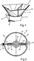
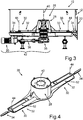
- Fig. 3 is the discharge device 26 along the in Fig. 2 marked section plane AA, wherein the funnel-shaped part 16 of the container 12 was again omitted.
- a planetary gear 36 is arranged on the underside of the cylindrical part 14 of the container 12 and is connected to the said interface of the connection body 28 of the discharge device 26, which interface is not shown here.
- the planetary gear 36 is driven by means of the motor 20 by means of a drive shaft 38.
- the discharge device 26 can thus be set in rotation about an axis of rotation 40 of the discharge device 26.
- the arm extensions 34 arranged on the outside on the main arms 32 in the radial direction are rotatably mounted on the respective main arms 32 about respective axes of rotation 44 running parallel to the axis of rotation 40.
- the arm extensions 34 can thus be pivoted or rotated relative to the main arms 32 about the axes of rotation 44.
- Fig. 4 the discharge device 26 is shown alone in a perspective view.
- the arm extensions 34 which are arranged on the outside in the radial direction, can again be clearly seen, which are arranged on the main arms 32 of the discharge device 26 so as to be rotatable about the axes of rotation 44.
- the arm extensions 34 are in the Figures 2 to 4 each shown in its neutral position, in which the respective longitudinal axes, not specified, of the main arms 32 and the arm extensions 34 are aligned parallel to one another.
- the Discharge device 26 on its largest span. The span is slightly smaller than an inner diameter of the cylindrical part 14 of the container 12.
- the discharge arms 30 thus comb with their maximum span across the bottom 24 of the container 12 and thus convey the maximum possible amount of biomass to the discharge opening 22.
- the arm extensions 34 are rotatably supported about the respective axis of rotation 44 such that, starting from the neutral position shown here, the arm extensions 34 can be rotated through 90 ° about the axis of rotation 44 relative to the respective main arm 32.
- the rotation about the axis of rotation 44 can take place to the right as well as to the left around the axis of rotation 44.
- the restoring elements 46 are respective tension springs, the same restoring moment is always exerted on the respective arm extensions 34 in the direction of their neutral position regardless of the direction of rotation about the axis of rotation 44.
- the respective main arms 32 have, in the region of their respective longitudinal ends, which face away from the connection body 28, which is not recognizable here, respective pins 62, on which respective cylindrical regions 64 of the arm extensions 34 are rotatably mounted about the respective axes of rotation 44.
- the cylindrical regions 64 are in each case a component of the respective bearing regions 56 of the arm extensions 34.
- a bushing 66 preferably made of polyamide, is arranged between the respective pins 62 and the cylindrical regions 64 of the arm extensions 34. The bushing 66 minimizes the friction between the pins 62 and the cylindrical regions 64 when the arm extensions 34 are pivoted or rotated about the respective axes of rotation 44 relative to the main arms 32.
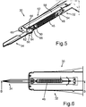
- FIG. 6 one of the two discharge arms 30 of the discharge device 26 is shown in a partially transparent top view.
- the arm extensions 34 about the respective axes of rotation 44 become relative to the main arms 32 pivoted.
- the arm extensions 34 are pivoted either counterclockwise or clockwise about the axes of rotation 44, which are not shown here. This can happen until the arm extensions 34 are arranged transversely to the main arms 32.
- Fig. 7 is one of the two discharge arms 30 in a longitudinal sectional view along the in Fig. 6 marked cutting plane BB shown.
- the arm extensions 34 are mounted on the main arms 32.
- the arrangement of the reset elements 46 can also be clearly seen here again.
- the described rotatable mounting and arrangement of the arm extensions 34 can ensure that when the discharge device 26 rotates about the axis of rotation 40 with a corresponding force effect in the circumferential direction - in relation to the axis of rotation 40 - the arm extensions 34 are pivoted or folded away about the respective axes of rotation 44 .
Landscapes
- Health & Medical Sciences (AREA)
- Life Sciences & Earth Sciences (AREA)
- Chemical & Material Sciences (AREA)
- Engineering & Computer Science (AREA)
- Organic Chemistry (AREA)
- Zoology (AREA)
- Bioinformatics & Cheminformatics (AREA)
- Wood Science & Technology (AREA)
- Molecular Biology (AREA)
- Genetics & Genomics (AREA)
- Biotechnology (AREA)
- Microbiology (AREA)
- Sustainable Development (AREA)
- Biomedical Technology (AREA)
- Biochemistry (AREA)
- General Engineering & Computer Science (AREA)
- General Health & Medical Sciences (AREA)
- Oil, Petroleum & Natural Gas (AREA)
- General Chemical & Material Sciences (AREA)
- Filling Or Emptying Of Bunkers, Hoppers, And Tanks (AREA)
Applications Claiming Priority (1)
| Application Number | Priority Date | Filing Date | Title |
|---|---|---|---|
| DE102019100407.1A DE102019100407B3 (de) | 2019-01-09 | 2019-01-09 | Austragsvorrichtung für ein Beschickungssystem zum Bereitstellen von Biomasse in einer Biogasanlage |
Publications (2)
| Publication Number | Publication Date |
|---|---|
| EP3680320A1 true EP3680320A1 (fr) | 2020-07-15 |
| EP3680320B1 EP3680320B1 (fr) | 2021-08-04 |
Family
ID=68840915
Family Applications (1)
| Application Number | Title | Priority Date | Filing Date |
|---|---|---|---|
| EP19214447.5A Active EP3680320B1 (fr) | 2019-01-09 | 2019-12-09 | Dispositif de décharge pour un système de chargement permettant de fournir de la biomasse dans une installation de biogaz |
Country Status (2)
| Country | Link |
|---|---|
| EP (1) | EP3680320B1 (fr) |
| DE (1) | DE102019100407B3 (fr) |
Cited By (1)
| Publication number | Priority date | Publication date | Assignee | Title |
|---|---|---|---|---|
| CN114836293A (zh) * | 2022-04-13 | 2022-08-02 | 广西福莱明生物制药有限公司 | 一种生物发酵工艺及发酵设备 |
Citations (5)
| Publication number | Priority date | Publication date | Assignee | Title |
|---|---|---|---|---|
| DE1891383U (de) * | 1964-02-13 | 1964-04-16 | Wilhelm Kemper Landmaschinenfa | Schraemmvorrichtung am boden eines futtersilos. |
| EP0529113A1 (fr) * | 1991-08-22 | 1993-03-03 | Schwäbische Hüttenwerke Gesellschaft mit beschränkter Haftung | Dispositif d'extraction pour silo |
| DE20008186U1 (de) * | 2000-05-06 | 2000-08-17 | U.T.S. Umwelt-Technik-Süd GmbH, 84419 Obertaufkirchen | Räum- und Austrageinrichtung für Sinkschichten an einem Fermenter zur anaeroben Fermentation von organischen Stoffen |
| EP1681344A1 (fr) * | 2005-01-14 | 2006-07-19 | U.T.S. Umwelt-Technik-Süd GmbH | Dispositif de chargement de matière solide d'un fermenteur d'une installation de biogaz |
| DE102011088319A1 (de) * | 2011-04-21 | 2012-10-25 | Lg Display Co., Ltd. | Substrat für eine Flüssigkristallanzeigevorrichtung mit berührungsempfindlichem Sensor in den Zellen und Herstellungsverfahren für dasselbe |
-
2019
- 2019-01-09 DE DE102019100407.1A patent/DE102019100407B3/de not_active Expired - Fee Related
- 2019-12-09 EP EP19214447.5A patent/EP3680320B1/fr active Active
Patent Citations (5)
| Publication number | Priority date | Publication date | Assignee | Title |
|---|---|---|---|---|
| DE1891383U (de) * | 1964-02-13 | 1964-04-16 | Wilhelm Kemper Landmaschinenfa | Schraemmvorrichtung am boden eines futtersilos. |
| EP0529113A1 (fr) * | 1991-08-22 | 1993-03-03 | Schwäbische Hüttenwerke Gesellschaft mit beschränkter Haftung | Dispositif d'extraction pour silo |
| DE20008186U1 (de) * | 2000-05-06 | 2000-08-17 | U.T.S. Umwelt-Technik-Süd GmbH, 84419 Obertaufkirchen | Räum- und Austrageinrichtung für Sinkschichten an einem Fermenter zur anaeroben Fermentation von organischen Stoffen |
| EP1681344A1 (fr) * | 2005-01-14 | 2006-07-19 | U.T.S. Umwelt-Technik-Süd GmbH | Dispositif de chargement de matière solide d'un fermenteur d'une installation de biogaz |
| DE102011088319A1 (de) * | 2011-04-21 | 2012-10-25 | Lg Display Co., Ltd. | Substrat für eine Flüssigkristallanzeigevorrichtung mit berührungsempfindlichem Sensor in den Zellen und Herstellungsverfahren für dasselbe |
Cited By (2)
| Publication number | Priority date | Publication date | Assignee | Title |
|---|---|---|---|---|
| CN114836293A (zh) * | 2022-04-13 | 2022-08-02 | 广西福莱明生物制药有限公司 | 一种生物发酵工艺及发酵设备 |
| CN114836293B (zh) * | 2022-04-13 | 2022-11-04 | 广西福莱明生物制药有限公司 | 一种生物发酵工艺及发酵设备 |
Also Published As
| Publication number | Publication date |
|---|---|
| EP3680320B1 (fr) | 2021-08-04 |
| DE102019100407B3 (de) | 2020-03-12 |
Similar Documents
| Publication | Publication Date | Title |
|---|---|---|
| DE102015206845B4 (de) | Schneidwerk zur Ganzpflanzenernte | |
| DE2132217A1 (de) | Dreschkorb-Einstellvorrichtung bei Maehdreschern | |
| DE69312986T2 (de) | Stalldungstreuer | |
| DE102016120528B4 (de) | Schneidmesser-Überlastsicherung | |
| EP2004914B1 (fr) | Centrifugeur-ejecteur | |
| EP1516121A1 (fr) | Installation d'energie eolienne | |
| EP3680320B1 (fr) | Dispositif de décharge pour un système de chargement permettant de fournir de la biomasse dans une installation de biogaz | |
| DE2254509A1 (de) | Kreiselheuwerbungsmaschine | |
| EP1864567B1 (fr) | Ramasseur | |
| DE2104564A1 (de) | Gras Erntemaschine | |
| DE69504323T2 (de) | Gerät zum streuen von material | |
| AT504636B1 (de) | Streuvorrichtung, insbesondere für einen miststreuer oder kompoststreuer | |
| DE19538370C1 (de) | Antrieb für eine Kolbensammelpresse für landwirtschaftliche Erntegüter | |
| EP4059339A1 (fr) | Engin d'abattage-façonnage | |
| DE1481094A1 (de) | Vorrichtung zum Dosieren von Erntegut | |
| DE602004002568T2 (de) | Misch- und verteilanlage, insbesondere für viehfutter | |
| EP4333611B1 (fr) | Dispositif de mélange pourvu d'une vis mélangeuse divisée et des sections de spires pouvant être entraînées indépendamment les unes des autres | |
| DE102005015236A1 (de) | Zweischeibenstreuer für Streugut, insbesondere Dünger, Salz oder dergleichen | |
| DE102011013243B4 (de) | Erntemaschine | |
| EP1092342B1 (fr) | Dispositif de pivotement pour la goulotte d'éjection de faucheuse-hacheuse | |
| DE102014103857A1 (de) | Schwenkbarer Futtermischer | |
| DE10231522B4 (de) | Verfahren zur Förderung von Getreide und ähnlich hochwertigen Schüttgut, insbesondere der Landwirtschaft und eine Vorrichtung zur Durchführung des Verfahrens | |
| DE202010010077U1 (de) | Gutaufnehmer | |
| DE102005023873B4 (de) | Mähmaschine | |
| EP1604562B1 (fr) | Véhicule de transport agricole |
Legal Events
| Date | Code | Title | Description |
|---|---|---|---|
| PUAI | Public reference made under article 153(3) epc to a published international application that has entered the european phase |
Free format text: ORIGINAL CODE: 0009012 |
|
| STAA | Information on the status of an ep patent application or granted ep patent |
Free format text: STATUS: THE APPLICATION HAS BEEN PUBLISHED |
|
| AK | Designated contracting states |
Kind code of ref document: A1 Designated state(s): AL AT BE BG CH CY CZ DE DK EE ES FI FR GB GR HR HU IE IS IT LI LT LU LV MC MK MT NL NO PL PT RO RS SE SI SK SM TR |
|
| AX | Request for extension of the european patent |
Extension state: BA ME |
|
| STAA | Information on the status of an ep patent application or granted ep patent |
Free format text: STATUS: REQUEST FOR EXAMINATION WAS MADE |
|
| 17P | Request for examination filed |
Effective date: 20210115 |
|
| RBV | Designated contracting states (corrected) |
Designated state(s): AL AT BE BG CH CY CZ DE DK EE ES FI FR GB GR HR HU IE IS IT LI LT LU LV MC MK MT NL NO PL PT RO RS SE SI SK SM TR |
|
| GRAP | Despatch of communication of intention to grant a patent |
Free format text: ORIGINAL CODE: EPIDOSNIGR1 |
|
| STAA | Information on the status of an ep patent application or granted ep patent |
Free format text: STATUS: GRANT OF PATENT IS INTENDED |
|
| INTG | Intention to grant announced |
Effective date: 20210316 |
|
| GRAS | Grant fee paid |
Free format text: ORIGINAL CODE: EPIDOSNIGR3 |
|
| GRAA | (expected) grant |
Free format text: ORIGINAL CODE: 0009210 |
|
| STAA | Information on the status of an ep patent application or granted ep patent |
Free format text: STATUS: THE PATENT HAS BEEN GRANTED |
|
| AK | Designated contracting states |
Kind code of ref document: B1 Designated state(s): AL AT BE BG CH CY CZ DE DK EE ES FI FR GB GR HR HU IE IS IT LI LT LU LV MC MK MT NL NO PL PT RO RS SE SI SK SM TR |
|
| REG | Reference to a national code |
Ref country code: GB Ref legal event code: FG4D Free format text: NOT ENGLISH |
|
| REG | Reference to a national code |
Ref country code: AT Ref legal event code: REF Ref document number: 1417020 Country of ref document: AT Kind code of ref document: T Effective date: 20210815 |
|
| REG | Reference to a national code |
Ref country code: CH Ref legal event code: EP |
|
| REG | Reference to a national code |
Ref country code: DE Ref legal event code: R096 Ref document number: 502019001962 Country of ref document: DE |
|
| REG | Reference to a national code |
Ref country code: IE Ref legal event code: FG4D Free format text: LANGUAGE OF EP DOCUMENT: GERMAN |
|
| REG | Reference to a national code |
Ref country code: LT Ref legal event code: MG9D |
|
| REG | Reference to a national code |
Ref country code: NL Ref legal event code: MP Effective date: 20210804 |
|
| PG25 | Lapsed in a contracting state [announced via postgrant information from national office to epo] |
Ref country code: NO Free format text: LAPSE BECAUSE OF FAILURE TO SUBMIT A TRANSLATION OF THE DESCRIPTION OR TO PAY THE FEE WITHIN THE PRESCRIBED TIME-LIMIT Effective date: 20211104 Ref country code: PT Free format text: LAPSE BECAUSE OF FAILURE TO SUBMIT A TRANSLATION OF THE DESCRIPTION OR TO PAY THE FEE WITHIN THE PRESCRIBED TIME-LIMIT Effective date: 20211206 Ref country code: HR Free format text: LAPSE BECAUSE OF FAILURE TO SUBMIT A TRANSLATION OF THE DESCRIPTION OR TO PAY THE FEE WITHIN THE PRESCRIBED TIME-LIMIT Effective date: 20210804 Ref country code: FI Free format text: LAPSE BECAUSE OF FAILURE TO SUBMIT A TRANSLATION OF THE DESCRIPTION OR TO PAY THE FEE WITHIN THE PRESCRIBED TIME-LIMIT Effective date: 20210804 Ref country code: BG Free format text: LAPSE BECAUSE OF FAILURE TO SUBMIT A TRANSLATION OF THE DESCRIPTION OR TO PAY THE FEE WITHIN THE PRESCRIBED TIME-LIMIT Effective date: 20211104 Ref country code: LT Free format text: LAPSE BECAUSE OF FAILURE TO SUBMIT A TRANSLATION OF THE DESCRIPTION OR TO PAY THE FEE WITHIN THE PRESCRIBED TIME-LIMIT Effective date: 20210804 Ref country code: SE Free format text: LAPSE BECAUSE OF FAILURE TO SUBMIT A TRANSLATION OF THE DESCRIPTION OR TO PAY THE FEE WITHIN THE PRESCRIBED TIME-LIMIT Effective date: 20210804 Ref country code: RS Free format text: LAPSE BECAUSE OF FAILURE TO SUBMIT A TRANSLATION OF THE DESCRIPTION OR TO PAY THE FEE WITHIN THE PRESCRIBED TIME-LIMIT Effective date: 20210804 Ref country code: ES Free format text: LAPSE BECAUSE OF FAILURE TO SUBMIT A TRANSLATION OF THE DESCRIPTION OR TO PAY THE FEE WITHIN THE PRESCRIBED TIME-LIMIT Effective date: 20210804 |
|
| PG25 | Lapsed in a contracting state [announced via postgrant information from national office to epo] |
Ref country code: PL Free format text: LAPSE BECAUSE OF FAILURE TO SUBMIT A TRANSLATION OF THE DESCRIPTION OR TO PAY THE FEE WITHIN THE PRESCRIBED TIME-LIMIT Effective date: 20210804 Ref country code: LV Free format text: LAPSE BECAUSE OF FAILURE TO SUBMIT A TRANSLATION OF THE DESCRIPTION OR TO PAY THE FEE WITHIN THE PRESCRIBED TIME-LIMIT Effective date: 20210804 Ref country code: GR Free format text: LAPSE BECAUSE OF FAILURE TO SUBMIT A TRANSLATION OF THE DESCRIPTION OR TO PAY THE FEE WITHIN THE PRESCRIBED TIME-LIMIT Effective date: 20211105 |
|
| PG25 | Lapsed in a contracting state [announced via postgrant information from national office to epo] |
Ref country code: NL Free format text: LAPSE BECAUSE OF FAILURE TO SUBMIT A TRANSLATION OF THE DESCRIPTION OR TO PAY THE FEE WITHIN THE PRESCRIBED TIME-LIMIT Effective date: 20210804 |
|
| PG25 | Lapsed in a contracting state [announced via postgrant information from national office to epo] |
Ref country code: DK Free format text: LAPSE BECAUSE OF FAILURE TO SUBMIT A TRANSLATION OF THE DESCRIPTION OR TO PAY THE FEE WITHIN THE PRESCRIBED TIME-LIMIT Effective date: 20210804 |
|
| REG | Reference to a national code |
Ref country code: DE Ref legal event code: R097 Ref document number: 502019001962 Country of ref document: DE |
|
| PG25 | Lapsed in a contracting state [announced via postgrant information from national office to epo] |
Ref country code: SM Free format text: LAPSE BECAUSE OF FAILURE TO SUBMIT A TRANSLATION OF THE DESCRIPTION OR TO PAY THE FEE WITHIN THE PRESCRIBED TIME-LIMIT Effective date: 20210804 Ref country code: SK Free format text: LAPSE BECAUSE OF FAILURE TO SUBMIT A TRANSLATION OF THE DESCRIPTION OR TO PAY THE FEE WITHIN THE PRESCRIBED TIME-LIMIT Effective date: 20210804 Ref country code: RO Free format text: LAPSE BECAUSE OF FAILURE TO SUBMIT A TRANSLATION OF THE DESCRIPTION OR TO PAY THE FEE WITHIN THE PRESCRIBED TIME-LIMIT Effective date: 20210804 Ref country code: EE Free format text: LAPSE BECAUSE OF FAILURE TO SUBMIT A TRANSLATION OF THE DESCRIPTION OR TO PAY THE FEE WITHIN THE PRESCRIBED TIME-LIMIT Effective date: 20210804 Ref country code: CZ Free format text: LAPSE BECAUSE OF FAILURE TO SUBMIT A TRANSLATION OF THE DESCRIPTION OR TO PAY THE FEE WITHIN THE PRESCRIBED TIME-LIMIT Effective date: 20210804 Ref country code: AL Free format text: LAPSE BECAUSE OF FAILURE TO SUBMIT A TRANSLATION OF THE DESCRIPTION OR TO PAY THE FEE WITHIN THE PRESCRIBED TIME-LIMIT Effective date: 20210804 |
|
| PLBE | No opposition filed within time limit |
Free format text: ORIGINAL CODE: 0009261 |
|
| STAA | Information on the status of an ep patent application or granted ep patent |
Free format text: STATUS: NO OPPOSITION FILED WITHIN TIME LIMIT |
|
| 26N | No opposition filed |
Effective date: 20220506 |
|
| PG25 | Lapsed in a contracting state [announced via postgrant information from national office to epo] |
Ref country code: MC Free format text: LAPSE BECAUSE OF FAILURE TO SUBMIT A TRANSLATION OF THE DESCRIPTION OR TO PAY THE FEE WITHIN THE PRESCRIBED TIME-LIMIT Effective date: 20210804 |
|
| PG25 | Lapsed in a contracting state [announced via postgrant information from national office to epo] |
Ref country code: SI Free format text: LAPSE BECAUSE OF FAILURE TO SUBMIT A TRANSLATION OF THE DESCRIPTION OR TO PAY THE FEE WITHIN THE PRESCRIBED TIME-LIMIT Effective date: 20210804 |
|
| REG | Reference to a national code |
Ref country code: BE Ref legal event code: MM Effective date: 20211231 |
|
| PG25 | Lapsed in a contracting state [announced via postgrant information from national office to epo] |
Ref country code: LU Free format text: LAPSE BECAUSE OF NON-PAYMENT OF DUE FEES Effective date: 20211209 Ref country code: IE Free format text: LAPSE BECAUSE OF NON-PAYMENT OF DUE FEES Effective date: 20211209 |
|
| PG25 | Lapsed in a contracting state [announced via postgrant information from national office to epo] |
Ref country code: BE Free format text: LAPSE BECAUSE OF NON-PAYMENT OF DUE FEES Effective date: 20211231 |
|
| PG25 | Lapsed in a contracting state [announced via postgrant information from national office to epo] |
Ref country code: CY Free format text: LAPSE BECAUSE OF FAILURE TO SUBMIT A TRANSLATION OF THE DESCRIPTION OR TO PAY THE FEE WITHIN THE PRESCRIBED TIME-LIMIT Effective date: 20210804 |
|
| PG25 | Lapsed in a contracting state [announced via postgrant information from national office to epo] |
Ref country code: HU Free format text: LAPSE BECAUSE OF FAILURE TO SUBMIT A TRANSLATION OF THE DESCRIPTION OR TO PAY THE FEE WITHIN THE PRESCRIBED TIME-LIMIT; INVALID AB INITIO Effective date: 20191209 |
|
| REG | Reference to a national code |
Ref country code: CH Ref legal event code: PL |
|
| PG25 | Lapsed in a contracting state [announced via postgrant information from national office to epo] |
Ref country code: LI Free format text: LAPSE BECAUSE OF NON-PAYMENT OF DUE FEES Effective date: 20221231 Ref country code: CH Free format text: LAPSE BECAUSE OF NON-PAYMENT OF DUE FEES Effective date: 20221231 |
|
| PG25 | Lapsed in a contracting state [announced via postgrant information from national office to epo] |
Ref country code: MK Free format text: LAPSE BECAUSE OF FAILURE TO SUBMIT A TRANSLATION OF THE DESCRIPTION OR TO PAY THE FEE WITHIN THE PRESCRIBED TIME-LIMIT Effective date: 20210804 |
|
| GBPC | Gb: european patent ceased through non-payment of renewal fee |
Effective date: 20231209 |
|
| PG25 | Lapsed in a contracting state [announced via postgrant information from national office to epo] |
Ref country code: MT Free format text: LAPSE BECAUSE OF FAILURE TO SUBMIT A TRANSLATION OF THE DESCRIPTION OR TO PAY THE FEE WITHIN THE PRESCRIBED TIME-LIMIT Effective date: 20210804 |
|
| PG25 | Lapsed in a contracting state [announced via postgrant information from national office to epo] |
Ref country code: GB Free format text: LAPSE BECAUSE OF NON-PAYMENT OF DUE FEES Effective date: 20231209 |
|
| PG25 | Lapsed in a contracting state [announced via postgrant information from national office to epo] |
Ref country code: GB Free format text: LAPSE BECAUSE OF NON-PAYMENT OF DUE FEES Effective date: 20231209 |
|
| PG25 | Lapsed in a contracting state [announced via postgrant information from national office to epo] |
Ref country code: TR Free format text: LAPSE BECAUSE OF FAILURE TO SUBMIT A TRANSLATION OF THE DESCRIPTION OR TO PAY THE FEE WITHIN THE PRESCRIBED TIME-LIMIT Effective date: 20210804 |
|
| PGFP | Annual fee paid to national office [announced via postgrant information from national office to epo] |
Ref country code: FR Payment date: 20251217 Year of fee payment: 7 |
|
| REG | Reference to a national code |
Ref country code: AT Ref legal event code: MM01 Ref document number: 1417020 Country of ref document: AT Kind code of ref document: T Effective date: 20241209 |
|
| PGFP | Annual fee paid to national office [announced via postgrant information from national office to epo] |
Ref country code: DE Payment date: 20251222 Year of fee payment: 7 |
|
| PG25 | Lapsed in a contracting state [announced via postgrant information from national office to epo] |
Ref country code: AT Free format text: LAPSE BECAUSE OF NON-PAYMENT OF DUE FEES Effective date: 20241209 |
|
| PGFP | Annual fee paid to national office [announced via postgrant information from national office to epo] |
Ref country code: AT Payment date: 20260410 Year of fee payment: 5 |
|
| PGFP | Annual fee paid to national office [announced via postgrant information from national office to epo] |
Ref country code: IT Payment date: 20251231 Year of fee payment: 7 |