EP3680425A1 - Agencement de commande de porte ainsi que porte - Google Patents
Agencement de commande de porte ainsi que porte Download PDFInfo
- Publication number
- EP3680425A1 EP3680425A1 EP19213549.9A EP19213549A EP3680425A1 EP 3680425 A1 EP3680425 A1 EP 3680425A1 EP 19213549 A EP19213549 A EP 19213549A EP 3680425 A1 EP3680425 A1 EP 3680425A1
- Authority
- EP
- European Patent Office
- Prior art keywords
- door
- rotation
- sleeve
- magnet
- unit
- Prior art date
- Legal status (The legal status is an assumption and is not a legal conclusion. Google has not performed a legal analysis and makes no representation as to the accuracy of the status listed.)
- Granted
Links
Images






Classifications
-
- E—FIXED CONSTRUCTIONS
- E05—LOCKS; KEYS; WINDOW OR DOOR FITTINGS; SAFES
- E05C—BOLTS OR FASTENING DEVICES FOR WINGS, SPECIALLY FOR DOORS OR WINDOWS
- E05C19/00—Other devices specially designed for securing wings, e.g. with suction cups
- E05C19/16—Devices holding the wing by magnetic or electromagnetic attraction
- E05C19/163—Devices holding the wing by magnetic or electromagnetic attraction a movable bolt being held in the striker by a permanent magnet
-
- E—FIXED CONSTRUCTIONS
- E05—LOCKS; KEYS; WINDOW OR DOOR FITTINGS; SAFES
- E05B—LOCKS; ACCESSORIES THEREFOR; HANDCUFFS
- E05B47/00—Operating or controlling locks or other fastening devices by electric or magnetic means
- E05B47/0038—Operating or controlling locks or other fastening devices by electric or magnetic means using permanent magnets
-
- E—FIXED CONSTRUCTIONS
- E05—LOCKS; KEYS; WINDOW OR DOOR FITTINGS; SAFES
- E05B—LOCKS; ACCESSORIES THEREFOR; HANDCUFFS
- E05B15/00—Other details of locks; Parts for engagement by bolts of fastening devices
- E05B15/0053—Other details of locks; Parts for engagement by bolts of fastening devices means providing a stable, i.e. indexed, position of lock parts
- E05B15/0073—Other details of locks; Parts for engagement by bolts of fastening devices means providing a stable, i.e. indexed, position of lock parts magnetically operated
-
- E—FIXED CONSTRUCTIONS
- E05—LOCKS; KEYS; WINDOW OR DOOR FITTINGS; SAFES
- E05B—LOCKS; ACCESSORIES THEREFOR; HANDCUFFS
- E05B41/00—Locks with visible indication as to whether the lock is locked or unlocked
-
- E—FIXED CONSTRUCTIONS
- E05—LOCKS; KEYS; WINDOW OR DOOR FITTINGS; SAFES
- E05B—LOCKS; ACCESSORIES THEREFOR; HANDCUFFS
- E05B47/00—Operating or controlling locks or other fastening devices by electric or magnetic means
- E05B47/0038—Operating or controlling locks or other fastening devices by electric or magnetic means using permanent magnets
- E05B47/004—Operating or controlling locks or other fastening devices by electric or magnetic means using permanent magnets the magnets acting directly on the bolt
-
- E—FIXED CONSTRUCTIONS
- E05—LOCKS; KEYS; WINDOW OR DOOR FITTINGS; SAFES
- E05B—LOCKS; ACCESSORIES THEREFOR; HANDCUFFS
- E05B63/00—Locks or fastenings with special structural characteristics
- E05B63/0052—Locks mounted on the "frame" cooperating with means on the "wing"
-
- E—FIXED CONSTRUCTIONS
- E05—LOCKS; KEYS; WINDOW OR DOOR FITTINGS; SAFES
- E05B—LOCKS; ACCESSORIES THEREFOR; HANDCUFFS
- E05B65/00—Locks or fastenings for special use
- E05B65/0025—Locks or fastenings for special use for glass wings
-
- E—FIXED CONSTRUCTIONS
- E05—LOCKS; KEYS; WINDOW OR DOOR FITTINGS; SAFES
- E05B—LOCKS; ACCESSORIES THEREFOR; HANDCUFFS
- E05B65/00—Locks or fastenings for special use
- E05B65/0035—Locks or fastenings for special use for privacy rooms, e.g. bathrooms
-
- E—FIXED CONSTRUCTIONS
- E05—LOCKS; KEYS; WINDOW OR DOOR FITTINGS; SAFES
- E05Y—INDEXING SCHEME ASSOCIATED WITH SUBCLASSES E05D AND E05F, RELATING TO CONSTRUCTION ELEMENTS, ELECTRIC CONTROL, POWER SUPPLY, POWER SIGNAL OR TRANSMISSION, USER INTERFACES, MOUNTING OR COUPLING, DETAILS, ACCESSORIES, AUXILIARY OPERATIONS NOT OTHERWISE PROVIDED FOR, APPLICATION THEREOF
- E05Y2201/00—Constructional elements; Accessories therefor
- E05Y2201/20—Brakes; Disengaging means; Holders; Stops; Valves; Accessories therefor
- E05Y2201/252—Type of friction
- E05Y2201/258—Magnetic or electromagnetic friction
-
- E—FIXED CONSTRUCTIONS
- E05—LOCKS; KEYS; WINDOW OR DOOR FITTINGS; SAFES
- E05Y—INDEXING SCHEME ASSOCIATED WITH SUBCLASSES E05D AND E05F, RELATING TO CONSTRUCTION ELEMENTS, ELECTRIC CONTROL, POWER SUPPLY, POWER SIGNAL OR TRANSMISSION, USER INTERFACES, MOUNTING OR COUPLING, DETAILS, ACCESSORIES, AUXILIARY OPERATIONS NOT OTHERWISE PROVIDED FOR, APPLICATION THEREOF
- E05Y2201/00—Constructional elements; Accessories therefor
- E05Y2201/40—Motors; Magnets; Springs; Weights; Accessories therefor
- E05Y2201/404—Function thereof
- E05Y2201/42—Function thereof for locking
-
- E—FIXED CONSTRUCTIONS
- E05—LOCKS; KEYS; WINDOW OR DOOR FITTINGS; SAFES
- E05Y—INDEXING SCHEME ASSOCIATED WITH SUBCLASSES E05D AND E05F, RELATING TO CONSTRUCTION ELEMENTS, ELECTRIC CONTROL, POWER SUPPLY, POWER SIGNAL OR TRANSMISSION, USER INTERFACES, MOUNTING OR COUPLING, DETAILS, ACCESSORIES, AUXILIARY OPERATIONS NOT OTHERWISE PROVIDED FOR, APPLICATION THEREOF
- E05Y2201/00—Constructional elements; Accessories therefor
- E05Y2201/40—Motors; Magnets; Springs; Weights; Accessories therefor
- E05Y2201/46—Magnets
Definitions
- the invention relates to a door control arrangement and a door.
- the door operating arrangement comprises a first operating unit, which comprises a first magnet rotatably guided therein with a first sleeve about a first axis of rotation and a drive unit for rotating the first sleeve.
- a second operating unit which comprises a second magnet, which is rotatably guided therein about a second axis of rotation with a second sleeve, and a second drive unit for rotating the second sleeve.
- Door control arrangements with two magnetically coupled door control units are used primarily with all-glass door leaves. With them it is possible to transmit forces through the closed surface of a door leaf. This eliminates the need for recesses or bores, which could otherwise damage the glass door body.
- a door arrangement is known in which a conventional mechanical door lock is arranged on a front surface of the door leaf.
- the current closed state of the door lock is transferred to the opposite side by means of a magnet arrangement.
- the display unit can also be used for emergency unlocking. However, this must be based on the magnetic force transmission between the door leaves. If the friction and resistance forces of the mechanical lock exceed the magnetic coupling forces between the two control units, an emergency release is not possible. A secure opening and closing on both sides cannot be guaranteed with this arrangement.
- the object of the invention is to improve the application possibilities of a magnetic coupling between two door control units. In this case, actuation should be equally possible from both sides. Furthermore, haptic feedback about the current operating state of the operating units is also to be given.
- the first operating unit has a first rotary locking device acting on the first sleeve and the second operating unit has a second rotary locking device acting on the second sleeve.
- the first magnet and the second magnet act repulsively on one another in the axial direction (i.e. along an axis of rotation assigned to the respective magnet). Due to the axial repulsion, the first anti-rotation device is effective in a first direction of rotation and the second anti-rotation device is effective in a second direction of rotation.
- the first direction of rotation and the second direction of rotation can be in the same direction or in opposite directions.
- the first magnet and the second magnet attract one another in the axial direction.
- the first anti-rotation device is effective against the first direction of rotation and the second anti-rotation device is effective against the second direction of rotation.
- the rotary locking devices are designed to prevent the rotation of the first sleeve or the second sleeve in the direction of rotation in which they are effective beyond a certain locking position. If a turnstile device assigned to a sleeve in a certain direction of rotation (continuous) is effective, a complete rotation of the sleeve in this direction of rotation is not possible, since further rotation is prevented at the latest when the locking position is reached.
- an operating state of the door operating arrangement - in particular the closed state "opened” / "closed” - is represented by the magnetic attraction or repulsion of the two magnets.
- the information transmission between the first control element and the second control element takes place magnetically.
- the current operating status can also be returned to a user by means of haptic feedback.
- a rotation or a complete rotation of a sleeve clockwise or counterclockwise is possible, a user can recognize whether the door control arrangement is in a first functional state or in a second functional state.
- This behavior is known, for example, from conventional mechanical door locks in which it is no longer possible to turn further in the "opening direction" at an opening position or to continue rotating in the "closing direction" in a closed position.
- a corresponding operating behavior can be provided without a direct mechanical coupling solely on the basis of magnetic interaction.
- first axis of rotation and the second axis of rotation run parallel to one another. Small deviations with a cutting angle of no more than 5 ° should also fall.
- the two axes of rotation are aligned with one another so that the first axis of rotation and the second axis of rotation are identical.
- the first rotary locking device has a first guide rotating in the circumferential direction (the rotary movement about the first axis of rotation) and a first engagement element interacting with the first guide.
- the first sleeve is held displaceably in the direction of the first axis of rotation (axial direction) relative to a housing of the first operating element.
- the first guide has a first longitudinal section running in the axial direction. When the longitudinal section is reached in a first direction of rotation, further turning is no longer possible. The movement is limited to the axial direction (or to a reverse rotation in the opposite direction) due to the engagement between the engagement element and the guide.
- the longitudinal section thus forms a first stop acting in this direction of rotation.
- the engagement element interacts with the first longitudinal section, displacement of the first sleeve in the axial direction is possible. Such a shift is triggered by the magnetic attraction or repulsion between the first magnet and the second magnet.
- the part running in the circumferential direction connects in the opposite direction.
- the guide is thus step-shaped and forms a second stop there, which is effective in the opposite direction of rotation.
- the direction of action of the turnstile device can be implemented as a function of an attractive or repulsive magnetic interaction.
- the guide is preferably designed in the form of a groove.
- the engagement element can be designed as a projection or pin which engages in the groove.
- the guide is arranged on an outer surface of the rotatable first sleeve. Accordingly, the engaging element is held in a rotationally fixed manner on the housing receiving the sleeve.
- the second rotary locking device of the second operating unit is preferably designed accordingly with a second guide, in particular a groove, having a second longitudinal section and a second engagement element interacting therewith.
- a freewheel is formed between the first drive unit and the first sleeve and / or between the second drive unit and the second sleeve.
- Free-wheeling is understood to mean that the rotary movement of the two elements is coupled in such a way that a relative angle of rotation can be set freely in a specific angular range.
- the freewheel is limited in both the one and the other direction of rotation by end stops at which the respective drive unit and the associated sleeve abut one another in a form-fitting manner. A further rotation of the drive unit in this direction takes the corresponding sleeve with it during the movement. If the rotary movement of the sleeve is blocked in this direction, the drive unit cannot be turned further.
- the freewheel preferably has an angular range of at least 90 °. There is a freewheel of 90 ° between the first drive unit and the first sleeve and between the second drive unit and the second sleeve possible, the first magnet and the second magnet can be moved at least between a relative positioning oriented in the same direction and an opposite orientation. A freewheel of at least 180 ° is particularly preferably provided.
- the rotational movement of the first sleeve and the rotational movement of the second sleeve are preferably blocked in both directions in the first functional state. This ensures that the first magnet and the second magnet are aligned in the same direction, in particular in parallel.
- the one rotational movement of the first sleeve against the first direction of rotation is preferably implemented by the first drive unit being inhibited or blocked in its rotation against a stop of the first freewheel.
- Permanent magnetized magnet arrangements are generally to be understood as “first magnet” and "second magnet”. In particular, this is a permanent magnet with a north pole and a south pole.
- the first magnet is designed as a bar magnet oriented perpendicular to the first axis of rotation and the second magnet as a bar magnet oriented perpendicular to the second axis of rotation.
- the "alignment” of the magnet is to be understood as the direction of its leading dipole moment.
- An orientation is to be assumed to be “vertical” if an angle of at least 80 °, preferably at least 85 °, is included between the dipole moment and the axial direction.
- the magnets can be moved between a same, in particular parallel and an opposite, in particular antiparallel position.
- the orientation is to be assumed to be "in the same direction” if the orientation of the first magnet and the orientation of the second magnet, projected onto a normal plane, form an angle of less than 90 ° on one of the axes of rotation. At an angle of more than 90 °, the orientation is "opposite".
- the dipole far field of the two magnets strengthens to form a stronger overall field.
- This can also be used to transfer the functional state to a sensor unit or a mechanical active group - such as a clamping unit.
- the two magnets (and thus the total magnetic field) are preferably oriented in the direction of the sensor unit or active group. In an opposite arrangement, the two magnets attract each other in the axial direction. The far magnetic field is reduced, which can also be used for transmission.
- the first operating unit is arranged at a distance from the second operating unit.
- an additional assembly for example an all-glass door leaf, can be arranged in the space between the first control unit and the second control unit. Breakthroughs in this intermediate assembly are not necessary.
- the first drive unit and the second drive unit can each be locked in a basic position and rotated through full revolutions with respect to this basic position.
- the drive units have a locking unit - in particular a cylinder lock.
- a suitable key can be inserted into the respective locking unit, so that the locking of the drive unit is released. After turning one or more complete turns, the key can only be removed in the basic position. The rotational mobility of the first drive unit then locks again in this.
- the first operating unit and the second operating unit are designed to be point or mirror symmetrical to one another.
- the orientation of the magnets can deviate from this.
- the invention also relates to a door with a door leaf that can be moved between an opening position that at least partially releases a door opening and a closing position that closes the door opening.
- the door leaf extends in a height direction, in a side direction and in a thickness direction.
- the extension in the thickness direction is clear (at least around a factor 10) less than in the vertical or lateral direction.
- the height direction is essentially parallel to the direction of gravity.
- the door leaf is closed in the side direction by two end faces forming side edges.
- the door has a previously described door operating arrangement, the first operating unit being arranged on a first front surface of the door leaf and the second operating unit being arranged on a second front surface of the door leaf, which lies opposite the first front surface in the thickness direction.
- the coupling of the first control unit to the second control unit can take place through the door leaf solely on the basis of magnetic interaction.
- the door leaf can in particular be designed as a pivoting or sliding door leaf.
- the door leaf has an extension of at most 2 cm in the thickness direction. Thin door leaves are particularly suitable for the use of the magnetically coupled control units.
- the door leaf is designed to be continuous at least in the area of the first operating unit and the second operating unit. No openings or openings are arranged in this area. This eliminates the need to provide such openings when manufacturing the door leaf or to add them later. This eliminates the additional effort and the risk of damaging or destroying the door leaf in such a processing step.
- the door preferably has a locking unit. This can be switched over by magnetic interaction with the door operating arrangement between a locked state locking the door leaf in the closed position and a release state releasing the door leaf.
- the magnetic interaction takes place with the magnetic field of the first magnet and / or the second magnet.
- the locking unit and the operating units are designed and arranged such that the door operating unit brings the locking unit into the locked state in the first functional state.
- the first magnet and the second magnet magnetically repel each other in the axial direction.
- the far field of the combination of the first magnet and the second magnet increases.
- the magnetic combination field strengthened in this way is suitable for triggering a closing action in the closing element.
- the release state of the locking unit is preferably achieved when the external magnetic field - induced by the combination of the first magnet and the second magnet - is weak or vanishingly small.
- Such an embodiment has the advantage that the operating unit can be brought into the first functional state inducing the closing process even outside the closed position of the door leaf. The door then locks when the door leaf reaches the closed position. Another mechanical interaction is - in contrast to mechanical door locks. not mandatory.
- the locking unit is arranged in a frame that surrounds the door opening.
- the locking effect on the door leaf can then be achieved in particular by a form fit to be achieved with the door leaf body itself or a striking plate arranged thereon.
- the Fig. 1 shows a door according to the invention with a door leaf 1 which can be moved between an opening state which at least partially releases a door opening 2 and a closing state which closes the door opening 2 and is shown here.
- the door leaf 1 extends in a height direction x a side direction y and in a thickness direction z.
- the door leaf 1 can be pivoted by means of at least one door hinge 3 about a pivot axis aligned in the height direction x between the open position and the closed position.
- the door opening 2 is bordered laterally by a door frame 4 which, in the closed position shown, receives the door leaf 1 which is designed as an all-glass door leaf.
- a first front side 1a of the door leaf 1 closes with the Mirror of the frame 4 is essentially flush with an offset of less than half a centimeter.
- a first operating unit 5a is arranged on the first front surface 1a of the door leaf 1.
- a second operating unit 5b is fastened on a second front surface 1b of the door leaf 1 opposite the first front surface 1a.
- the first control unit 5a and the second control unit 5b each have a housing 6a and 6b formed as a handle.
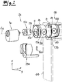
- the first control unit 5a is shown in an exploded view with the housing 6a omitted.
- the opposite housing 6b is arranged in dashed lines with the components accommodated therein in the regular arrangement.
- the first operating unit 5a comprises a first sleeve 7a, in which a first magnet 8a is rotatably guided about an axis of rotation d running in the thickness direction z.
- the second control unit 5b is thus magnetically coupled and has a second sleeve 7b in which a second magnet 8b is guided so as to be rotatable about the axis of rotation d.
- the first sleeve 7a and the second sleeve 7b have a cylindrical outer surface which is held in a form-fitting manner in a cylindrical cavity of the respective housing 6a, 6b and rotatable about the axis of rotation d.
- the first sleeve 7a can be rotated by a drive unit, which in the exemplary embodiment shown is formed by a first cylinder lock 9a and a first coupling element 10a.
- the cylinder lock 9a is locked in the basic position shown without an inserted key. Accordingly, the coupling piece 10a is also not rotatable.
- To the Coupling piece 10a is also arranged on the outside of a first cam 11a, which engages in an associated recess 12a of the first sleeve 7a.
- the recess 12a has a clear oversize compared to the cam 11a, so that the first sleeve 7a can be freely rotated with respect to the coupling element 10a with a freewheel of approximately 180 °.
- the coupling element 10a has a cylindrical middle part which bears in a form-fitting manner in an at least partially cylindrical bore in the sleeve 7a.
- the cam 11a projects radially from this. In the axial direction of the first axis of rotation d 1 , the recess 12a is larger than the extent of the cam 11a. A relative axial displacement of the first sleeve 7a relative to the coupling element 10a is thus possible.
- the coupling element 10a is held by a holder 13a in the axial direction di / z and is rotatably guided.
- the holder 13a also carries a pin 14a.
- This pin 14a is part of a first anti-rotation device.
- the anti-rotation device further comprises a groove 15a arranged in the circumferential direction on the sleeve 7a.
- the magnets 8a, 8b are in each case parallel bar magnets aligned in the lateral direction y.
- the north pole arranged at the end is indicated by a letter N.
- the mode of operation of the first rotary locking device 14a, 15a is shown in FIG Fig. 3 recognizable.
- the first guide formed by the first groove 15a has a first longitudinal section 16a which extends in the axial direction d / z.
- the groove 15a forms a step-shaped shoulder with a first stop 17a and a second stop 17b.
- the first sleeve 7a and the second sleeve 7b are each displaced outward from the door leaf 1 due to magnetic repulsion.
- the first pin 14a is positioned in the first longitudinal section 16a or the second pin 14b is in the second longitudinal section 16b, depending on the axial magnetic attraction or repulsion, there is also the transition to a second one Position possible in which the distance of the respective sleeve to the door leaf 1 is smaller. Since in the functional state shown the pin 14a bears against the first stop 17a, it cannot be turned counterclockwise (with a view of the first front side 1a of the door leaf 1). The first rotation lock device is thus effective in the first direction of rotation a in this state. In the event of an axial attraction, the pin 14a would come into contact with the second stop 17b, so that the first anti-rotation device would be effective counter to the first direction of rotation a.
- the second control element 5b is identical to the first control element 5a and is only attached after a rotation through 180 ° about the vertical axis x on the opposite front surface 1b. Only the relative orientation of the magnet differs, so that in the first functional state shown, the first magnet 8a and the second magnet 8b are arranged parallel to one another.
- the corresponding modules of the second control unit 5b each have the same reference numerals, these being provided with the index “b”. It is clear that the second direction of rotation, in which the second rotation lock arrangement 14b, 15b is effective in the first functional state shown, is also counterclockwise in FIG Direction of view of the assigned front surface 1b of the door leaf. In absolute terms, the first direction of rotation a is opposite to the second direction of rotation b.
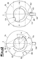
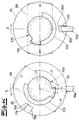
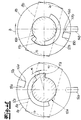
- the switchover function between the first functional state is in the Figures 4A to 4G shown.
- the views are each to be understood as a diagram with a view of the first front side 1a of the door leaf - that is, with a view in the thickness direction z.
- the relevant assemblies of the first operator unit 5a are shown in the left half of the figure and the corresponding assemblies of the second operator unit 5b, which are arranged behind them, are shown in the right half of the image.
- the interaction of the drive unit, the freewheel and the respective anti-rotation devices are to be explained.
- the assemblies of the first control arrangement 5a and the second control arrangement 5b arranged one behind the other in the view are shown side by side.
- the first functional position represents the closed state of the door operating unit designed as a magnetic door lock.
- the first direction of rotation a of the first door operating unit and the second direction of rotation b of the second operating unit each represent a “closing direction”. Continued rotation in this direction from the closed state will be prevented.
- the closing direction is therefore defined as a counterclockwise direction both from the first door leaf front 1a and from the second door front 1b.
- a deflection gear can be provided in the drive unit 9a of the first operating part 5a, which reverses the direction of rotation of the key during the transmission to the cam 11a.
- FIG. 4B A functional position is shown in which the first drive 10a, 11a is rotated by an angle of approximately 60 ° against the first direction of rotation a. Due to the repulsive torque between the first magnet 8a and the second magnet 8b, the first sleeve 7a is carried along in spite of the existing freewheel. Rotation of the second sleeve 7b is blocked on both sides, so that the second half of the image remains unchanged. In this position, the first magnet 8a and the second magnet 8b are still arranged in the same direction, so that a repulsion reaction takes place in the axial direction.
- the orientation of the first magnet 8a and the orientation of the second magnet 8b include an angle of approximately 120 °. Thus, they are to be regarded as "opposite", which leads to an axial attraction.
- the direction of action of the second rotary locking device changes: now the second pin 14b is in contact with the fourth stop 18b, so that both the locking device formed with the groove 15b and the pin 14b as well as the positive connection between the second cam 11b and the recess 12b of the second Prevent sleeve 7b from rotating in the opposite direction of rotation d.
- the torque acting on the second sleeve 7b is oriented exactly in this direction, so that there is no movement.
- the first cam 11a When turning further, the first cam 11a now moves within the freewheel without the first sleeve 7a moving further. Only when the end position is reached (angle of rotation ⁇ of 360 °) does the first cam 11a reach the right-hand stop of the freewheel and take the first sleeve 7a with it for a small angular amount. Since the second rotary locking device is effective in the tightened state (second functional state) against the second direction of rotation b, the second sleeve 7b can - as in FIG Figure 4E - shown rotate by a corresponding angle. In this closed position, any key can be removed from the first lock 9a again, since a complete revolution has been carried out.
- the first magnet 8a and the second magnet 8b are arranged in opposite directions - antiparallel - so that there is a second functional state. From this functional position, further rotation of the first drive 9a, 10a against the first direction of rotation a by one complete revolution is not possible.
- both the first sleeve 7a and the second sleeve 7b rotated (due to magnetic coupling).
- the pin 14a again reaches the position of the longitudinal section 16a. Because of the attractive interaction between the first magnet 8a and the second magnet 8b, the anti-rotation device is effective against the first direction of rotation a.
Landscapes
- Engineering & Computer Science (AREA)
- Physics & Mathematics (AREA)
- Electromagnetism (AREA)
- Mechanical Engineering (AREA)
- Structural Engineering (AREA)
- Lock And Its Accessories (AREA)
- Power-Operated Mechanisms For Wings (AREA)
- Casings For Electric Apparatus (AREA)
Priority Applications (1)
| Application Number | Priority Date | Filing Date | Title |
|---|---|---|---|
| PL19213549T PL3680425T3 (pl) | 2019-01-11 | 2019-12-04 | Układ obsługi drzwi oraz drzwi |
Applications Claiming Priority (1)
| Application Number | Priority Date | Filing Date | Title |
|---|---|---|---|
| DE102019100643.0A DE102019100643A1 (de) | 2019-01-11 | 2019-01-11 | Türbedienanordnung sowie Tür |
Publications (2)
| Publication Number | Publication Date |
|---|---|
| EP3680425A1 true EP3680425A1 (fr) | 2020-07-15 |
| EP3680425B1 EP3680425B1 (fr) | 2021-03-03 |
Family
ID=68771518
Family Applications (1)
| Application Number | Title | Priority Date | Filing Date |
|---|---|---|---|
| EP19213549.9A Active EP3680425B1 (fr) | 2019-01-11 | 2019-12-04 | Agencement de commande de porte ainsi que porte |
Country Status (7)
| Country | Link |
|---|---|
| US (1) | US11365572B2 (fr) |
| EP (1) | EP3680425B1 (fr) |
| CN (1) | CN111434874A (fr) |
| DE (1) | DE102019100643A1 (fr) |
| ES (1) | ES2877153T3 (fr) |
| PL (1) | PL3680425T3 (fr) |
| RU (1) | RU2724851C1 (fr) |
Families Citing this family (1)
| Publication number | Priority date | Publication date | Assignee | Title |
|---|---|---|---|---|
| DE102019100639B3 (de) * | 2019-01-11 | 2020-03-19 | Simonswerk Gmbh | Türbedienanordnung sowie Tür |
Citations (2)
| Publication number | Priority date | Publication date | Assignee | Title |
|---|---|---|---|---|
| DE202004009405U1 (de) | 2004-06-14 | 2004-08-19 | Gang Gwo Industrial Co., Ltd., Ta Liao | Schloss mit Anzeigefunktion für rahmenlose Glastür |
| EP2930292A1 (fr) * | 2014-04-01 | 2015-10-14 | DOM Sicherheitstechnik GmbH & Co. KG | Système de couplage électromécanique doté d'un commutateur rotatif magnétique et procédé |
Family Cites Families (19)
| Publication number | Priority date | Publication date | Assignee | Title |
|---|---|---|---|---|
| GB1104933A (en) * | 1964-02-13 | 1968-03-06 | Angus Gordon Melville Clark | Improved fastening means |
| US3837195A (en) * | 1973-02-08 | 1974-09-24 | E Pelto | Magnetic pin lock |
| FR2763630B3 (fr) * | 1997-05-20 | 1999-04-23 | Chin Chung Chang | Verrou pour porte en verre |
| US6363584B1 (en) * | 2000-01-20 | 2002-04-02 | George Gero | Cuff link with changeable element |
| US6929291B2 (en) * | 2003-07-28 | 2005-08-16 | Inventec Corp. | Magnetic lock |
| FR2872846B1 (fr) * | 2004-07-06 | 2007-05-11 | Gang Gwo Ind Co Ltd | Serrure de porte en verre sans cadre avec fonction d'indication |
| US20070007775A1 (en) * | 2005-07-05 | 2007-01-11 | Gallas William N | Rotatable bipolar phased magnetic locking system for door |
| JP2008261138A (ja) * | 2007-04-11 | 2008-10-30 | Asahi Kasei Homes Kk | 扉の施錠解錠装置及び施錠解錠表示装置 |
| TWM321464U (en) * | 2007-04-13 | 2007-11-01 | Chin Fa Electrical Engineering | Magnetic seal structure of auto door |
| US8016330B2 (en) * | 2008-05-20 | 2011-09-13 | Correalated Magnetics Research, LLC | Appliance safety apparatus, systems, and methods |
| CN201287082Y (zh) * | 2008-09-26 | 2009-08-12 | 中山市生科试剂仪器有限公司 | 具有门盖自锁功能的多功能液体离心机 |
| MX2011011808A (es) * | 2009-05-07 | 2012-02-13 | Rosemarie Wysoczki De Sanchez | Cerrojo magnetico, llave magnetica y combinacion de los mismos. |
| EP2527573A1 (fr) * | 2011-05-24 | 2012-11-28 | Caterpillar, Inc. | Fixation de retenue |
| CN102493735A (zh) * | 2011-12-18 | 2012-06-13 | 青岛雷尔威机械制造有限公司 | 一种轨道车辆感应式电动拉门装置 |
| EP3162988B1 (fr) * | 2015-10-29 | 2018-08-15 | BKS GmbH | Dispositif de fermeture pour une porte |
| WO2017181072A1 (fr) * | 2016-04-15 | 2017-10-19 | Odl, Incorporated | Ensemble porte pour verrouillage mutuel sélectif de portes opposées |
| US10145143B1 (en) * | 2017-06-06 | 2018-12-04 | Schlage Lock Company Llc | Lever return mechanism using magnets |
| DE102019100637A1 (de) * | 2019-01-11 | 2020-07-16 | Simonswerk Gmbh | Magnetschloss sowie Tür |
| DE102019100639B3 (de) * | 2019-01-11 | 2020-03-19 | Simonswerk Gmbh | Türbedienanordnung sowie Tür |
-
2019
- 2019-01-11 DE DE102019100643.0A patent/DE102019100643A1/de not_active Withdrawn
- 2019-12-04 ES ES19213549T patent/ES2877153T3/es active Active
- 2019-12-04 EP EP19213549.9A patent/EP3680425B1/fr active Active
- 2019-12-04 PL PL19213549T patent/PL3680425T3/pl unknown
-
2020
- 2020-01-08 US US16/736,952 patent/US11365572B2/en active Active
- 2020-01-09 RU RU2020100018A patent/RU2724851C1/ru active
- 2020-01-09 CN CN202010020052.0A patent/CN111434874A/zh active Pending
Patent Citations (2)
| Publication number | Priority date | Publication date | Assignee | Title |
|---|---|---|---|---|
| DE202004009405U1 (de) | 2004-06-14 | 2004-08-19 | Gang Gwo Industrial Co., Ltd., Ta Liao | Schloss mit Anzeigefunktion für rahmenlose Glastür |
| EP2930292A1 (fr) * | 2014-04-01 | 2015-10-14 | DOM Sicherheitstechnik GmbH & Co. KG | Système de couplage électromécanique doté d'un commutateur rotatif magnétique et procédé |
Also Published As
| Publication number | Publication date |
|---|---|
| DE102019100643A1 (de) | 2020-07-16 |
| CN111434874A (zh) | 2020-07-21 |
| ES2877153T3 (es) | 2021-11-16 |
| PL3680425T3 (pl) | 2021-09-06 |
| RU2724851C1 (ru) | 2020-06-25 |
| EP3680425B1 (fr) | 2021-03-03 |
| US20200224470A1 (en) | 2020-07-16 |
| US11365572B2 (en) | 2022-06-21 |
Similar Documents
| Publication | Publication Date | Title |
|---|---|---|
| EP1576246B1 (fr) | Dispositif de verrouillage | |
| DE102007044088B9 (de) | Binär codierter Schlüssel und manipulationssicheres Schloss | |
| DE60114487T2 (de) | Verriegelungsmechanismus für elektronische Schlösser | |
| DE68902680T2 (de) | Treibstangenverschluss fuer tueren, fenster o.dgl. | |
| DE3632904C2 (fr) | ||
| EP2302149B1 (fr) | Dispositif d'actionnement, par exemple cylindre de fermeture ou garniture de poignée de porte, doté d'un organe de commutation pouvant se rabattre magnétiquement par un élément de commutation | |
| EP3680426A1 (fr) | Serrure magnétique ainsi que porte | |
| DE102012111085A1 (de) | Türöffner | |
| EP3680428A1 (fr) | Dispositif de commande de porte ainsi que porte | |
| EP3680425B1 (fr) | Agencement de commande de porte ainsi que porte | |
| EP2715019B1 (fr) | Verrouillage de portière de véhicule à moteur | |
| DE112007002578B4 (de) | Schließzylinder | |
| EP0908585B1 (fr) | Ferrure avec une poignée verrouillable pour des fenêtres, des portes ou similaires | |
| EP2543797B1 (fr) | Installation d'ouverture de porte avec aimant permanent | |
| DE202011105510U1 (de) | Türöffner mit Sperr-Riegel | |
| DE4407912A1 (de) | Elektromechanisches Schloß | |
| DE69807608T2 (de) | Schliessvorrichtung, insbesondere Einsteckschloss mit einer Falle, für eine Fenstertür oder dergleichen | |
| DE112022006350T5 (de) | Anti-Schlag-Schloss | |
| WO2007104295A1 (fr) | Serrure pour une porte de maison ou d'appartement | |
| DE9210719U1 (de) | Türschloß | |
| DE102004048467B4 (de) | Betätigungsvorrichtung für ein Türschloss | |
| EP2754791A1 (fr) | Serrure de crémone | |
| EP2320013B1 (fr) | Armature dotée d'une transmission de renvoi | |
| DE102012010439B4 (de) | Türöffner mit Sperr-Riegel | |
| EP2505749B1 (fr) | Cylindre de fermeture pour un verrou |
Legal Events
| Date | Code | Title | Description |
|---|---|---|---|
| PUAI | Public reference made under article 153(3) epc to a published international application that has entered the european phase |
Free format text: ORIGINAL CODE: 0009012 |
|
| STAA | Information on the status of an ep patent application or granted ep patent |
Free format text: STATUS: THE APPLICATION HAS BEEN PUBLISHED |
|
| AK | Designated contracting states |
Kind code of ref document: A1 Designated state(s): AL AT BE BG CH CY CZ DE DK EE ES FI FR GB GR HR HU IE IS IT LI LT LU LV MC MK MT NL NO PL PT RO RS SE SI SK SM TR |
|
| AX | Request for extension of the european patent |
Extension state: BA ME |
|
| STAA | Information on the status of an ep patent application or granted ep patent |
Free format text: STATUS: REQUEST FOR EXAMINATION WAS MADE |
|
| 17P | Request for examination filed |
Effective date: 20200730 |
|
| RBV | Designated contracting states (corrected) |
Designated state(s): AL AT BE BG CH CY CZ DE DK EE ES FI FR GB GR HR HU IE IS IT LI LT LU LV MC MK MT NL NO PL PT RO RS SE SI SK SM TR |
|
| GRAP | Despatch of communication of intention to grant a patent |
Free format text: ORIGINAL CODE: EPIDOSNIGR1 |
|
| STAA | Information on the status of an ep patent application or granted ep patent |
Free format text: STATUS: GRANT OF PATENT IS INTENDED |
|
| INTG | Intention to grant announced |
Effective date: 20200930 |
|
| GRAS | Grant fee paid |
Free format text: ORIGINAL CODE: EPIDOSNIGR3 |
|
| RIN1 | Information on inventor provided before grant (corrected) |
Inventor name: KAUPMANN, FELIX Inventor name: ELLEFRED, JOERG |
|
| GRAA | (expected) grant |
Free format text: ORIGINAL CODE: 0009210 |
|
| STAA | Information on the status of an ep patent application or granted ep patent |
Free format text: STATUS: THE PATENT HAS BEEN GRANTED |
|
| AK | Designated contracting states |
Kind code of ref document: B1 Designated state(s): AL AT BE BG CH CY CZ DE DK EE ES FI FR GB GR HR HU IE IS IT LI LT LU LV MC MK MT NL NO PL PT RO RS SE SI SK SM TR |
|
| REG | Reference to a national code |
Ref country code: GB Ref legal event code: FG4D Free format text: NOT ENGLISH |
|
| REG | Reference to a national code |
Ref country code: CH Ref legal event code: EP Ref country code: AT Ref legal event code: REF Ref document number: 1367359 Country of ref document: AT Kind code of ref document: T Effective date: 20210315 |
|
| REG | Reference to a national code |
Ref country code: DE Ref legal event code: R096 Ref document number: 502019000909 Country of ref document: DE |
|
| REG | Reference to a national code |
Ref country code: IE Ref legal event code: FG4D Free format text: LANGUAGE OF EP DOCUMENT: GERMAN |
|
| REG | Reference to a national code |
Ref country code: NL Ref legal event code: FP |
|
| REG | Reference to a national code |
Ref country code: LT Ref legal event code: MG9D |
|
| PG25 | Lapsed in a contracting state [announced via postgrant information from national office to epo] |
Ref country code: HR Free format text: LAPSE BECAUSE OF FAILURE TO SUBMIT A TRANSLATION OF THE DESCRIPTION OR TO PAY THE FEE WITHIN THE PRESCRIBED TIME-LIMIT Effective date: 20210303 Ref country code: BG Free format text: LAPSE BECAUSE OF FAILURE TO SUBMIT A TRANSLATION OF THE DESCRIPTION OR TO PAY THE FEE WITHIN THE PRESCRIBED TIME-LIMIT Effective date: 20210603 Ref country code: GR Free format text: LAPSE BECAUSE OF FAILURE TO SUBMIT A TRANSLATION OF THE DESCRIPTION OR TO PAY THE FEE WITHIN THE PRESCRIBED TIME-LIMIT Effective date: 20210604 Ref country code: FI Free format text: LAPSE BECAUSE OF FAILURE TO SUBMIT A TRANSLATION OF THE DESCRIPTION OR TO PAY THE FEE WITHIN THE PRESCRIBED TIME-LIMIT Effective date: 20210303 Ref country code: NO Free format text: LAPSE BECAUSE OF FAILURE TO SUBMIT A TRANSLATION OF THE DESCRIPTION OR TO PAY THE FEE WITHIN THE PRESCRIBED TIME-LIMIT Effective date: 20210603 Ref country code: LT Free format text: LAPSE BECAUSE OF FAILURE TO SUBMIT A TRANSLATION OF THE DESCRIPTION OR TO PAY THE FEE WITHIN THE PRESCRIBED TIME-LIMIT Effective date: 20210303 |
|
| PG25 | Lapsed in a contracting state [announced via postgrant information from national office to epo] |
Ref country code: LV Free format text: LAPSE BECAUSE OF FAILURE TO SUBMIT A TRANSLATION OF THE DESCRIPTION OR TO PAY THE FEE WITHIN THE PRESCRIBED TIME-LIMIT Effective date: 20210303 Ref country code: SE Free format text: LAPSE BECAUSE OF FAILURE TO SUBMIT A TRANSLATION OF THE DESCRIPTION OR TO PAY THE FEE WITHIN THE PRESCRIBED TIME-LIMIT Effective date: 20210303 Ref country code: RS Free format text: LAPSE BECAUSE OF FAILURE TO SUBMIT A TRANSLATION OF THE DESCRIPTION OR TO PAY THE FEE WITHIN THE PRESCRIBED TIME-LIMIT Effective date: 20210303 |
|
| PG25 | Lapsed in a contracting state [announced via postgrant information from national office to epo] |
Ref country code: EE Free format text: LAPSE BECAUSE OF FAILURE TO SUBMIT A TRANSLATION OF THE DESCRIPTION OR TO PAY THE FEE WITHIN THE PRESCRIBED TIME-LIMIT Effective date: 20210303 Ref country code: SM Free format text: LAPSE BECAUSE OF FAILURE TO SUBMIT A TRANSLATION OF THE DESCRIPTION OR TO PAY THE FEE WITHIN THE PRESCRIBED TIME-LIMIT Effective date: 20210303 |
|
| REG | Reference to a national code |
Ref country code: ES Ref legal event code: FG2A Ref document number: 2877153 Country of ref document: ES Kind code of ref document: T3 Effective date: 20211116 |
|
| PG25 | Lapsed in a contracting state [announced via postgrant information from national office to epo] |
Ref country code: IS Free format text: LAPSE BECAUSE OF FAILURE TO SUBMIT A TRANSLATION OF THE DESCRIPTION OR TO PAY THE FEE WITHIN THE PRESCRIBED TIME-LIMIT Effective date: 20210703 Ref country code: PT Free format text: LAPSE BECAUSE OF FAILURE TO SUBMIT A TRANSLATION OF THE DESCRIPTION OR TO PAY THE FEE WITHIN THE PRESCRIBED TIME-LIMIT Effective date: 20210705 Ref country code: RO Free format text: LAPSE BECAUSE OF FAILURE TO SUBMIT A TRANSLATION OF THE DESCRIPTION OR TO PAY THE FEE WITHIN THE PRESCRIBED TIME-LIMIT Effective date: 20210303 Ref country code: SK Free format text: LAPSE BECAUSE OF FAILURE TO SUBMIT A TRANSLATION OF THE DESCRIPTION OR TO PAY THE FEE WITHIN THE PRESCRIBED TIME-LIMIT Effective date: 20210303 |
|
| REG | Reference to a national code |
Ref country code: DE Ref legal event code: R097 Ref document number: 502019000909 Country of ref document: DE |
|
| PLBE | No opposition filed within time limit |
Free format text: ORIGINAL CODE: 0009261 |
|
| STAA | Information on the status of an ep patent application or granted ep patent |
Free format text: STATUS: NO OPPOSITION FILED WITHIN TIME LIMIT |
|
| PG25 | Lapsed in a contracting state [announced via postgrant information from national office to epo] |
Ref country code: DK Free format text: LAPSE BECAUSE OF FAILURE TO SUBMIT A TRANSLATION OF THE DESCRIPTION OR TO PAY THE FEE WITHIN THE PRESCRIBED TIME-LIMIT Effective date: 20210303 Ref country code: AL Free format text: LAPSE BECAUSE OF FAILURE TO SUBMIT A TRANSLATION OF THE DESCRIPTION OR TO PAY THE FEE WITHIN THE PRESCRIBED TIME-LIMIT Effective date: 20210303 |
|
| 26N | No opposition filed |
Effective date: 20211206 |
|
| PG25 | Lapsed in a contracting state [announced via postgrant information from national office to epo] |
Ref country code: IS Free format text: LAPSE BECAUSE OF FAILURE TO SUBMIT A TRANSLATION OF THE DESCRIPTION OR TO PAY THE FEE WITHIN THE PRESCRIBED TIME-LIMIT Effective date: 20210703 |
|
| PG25 | Lapsed in a contracting state [announced via postgrant information from national office to epo] |
Ref country code: MC Free format text: LAPSE BECAUSE OF FAILURE TO SUBMIT A TRANSLATION OF THE DESCRIPTION OR TO PAY THE FEE WITHIN THE PRESCRIBED TIME-LIMIT Effective date: 20210303 Ref country code: CZ Free format text: LAPSE BECAUSE OF NON-PAYMENT OF DUE FEES Effective date: 20211204 |
|
| REG | Reference to a national code |
Ref country code: BE Ref legal event code: MM Effective date: 20211231 |
|
| PG25 | Lapsed in a contracting state [announced via postgrant information from national office to epo] |
Ref country code: LU Free format text: LAPSE BECAUSE OF NON-PAYMENT OF DUE FEES Effective date: 20211204 Ref country code: IE Free format text: LAPSE BECAUSE OF NON-PAYMENT OF DUE FEES Effective date: 20211204 |
|
| PG25 | Lapsed in a contracting state [announced via postgrant information from national office to epo] |
Ref country code: FR Free format text: LAPSE BECAUSE OF NON-PAYMENT OF DUE FEES Effective date: 20211231 Ref country code: BE Free format text: LAPSE BECAUSE OF NON-PAYMENT OF DUE FEES Effective date: 20211231 |
|
| REG | Reference to a national code |
Ref country code: ES Ref legal event code: FD2A Effective date: 20230202 |
|
| PG25 | Lapsed in a contracting state [announced via postgrant information from national office to epo] |
Ref country code: ES Free format text: LAPSE BECAUSE OF NON-PAYMENT OF DUE FEES Effective date: 20211205 |
|
| PGFP | Annual fee paid to national office [announced via postgrant information from national office to epo] |
Ref country code: IT Payment date: 20221231 Year of fee payment: 4 |
|
| PG25 | Lapsed in a contracting state [announced via postgrant information from national office to epo] |
Ref country code: CY Free format text: LAPSE BECAUSE OF FAILURE TO SUBMIT A TRANSLATION OF THE DESCRIPTION OR TO PAY THE FEE WITHIN THE PRESCRIBED TIME-LIMIT Effective date: 20210303 |
|
| PG25 | Lapsed in a contracting state [announced via postgrant information from national office to epo] |
Ref country code: HU Free format text: LAPSE BECAUSE OF FAILURE TO SUBMIT A TRANSLATION OF THE DESCRIPTION OR TO PAY THE FEE WITHIN THE PRESCRIBED TIME-LIMIT; INVALID AB INITIO Effective date: 20191204 |
|
| REG | Reference to a national code |
Ref country code: CH Ref legal event code: PL |
|
| REG | Reference to a national code |
Ref country code: NL Ref legal event code: MM Effective date: 20230101 |
|
| PG25 | Lapsed in a contracting state [announced via postgrant information from national office to epo] |
Ref country code: SI Free format text: LAPSE BECAUSE OF FAILURE TO SUBMIT A TRANSLATION OF THE DESCRIPTION OR TO PAY THE FEE WITHIN THE PRESCRIBED TIME-LIMIT Effective date: 20210303 Ref country code: NL Free format text: LAPSE BECAUSE OF NON-PAYMENT OF DUE FEES Effective date: 20230101 |
|
| PG25 | Lapsed in a contracting state [announced via postgrant information from national office to epo] |
Ref country code: LI Free format text: LAPSE BECAUSE OF NON-PAYMENT OF DUE FEES Effective date: 20221231 Ref country code: CH Free format text: LAPSE BECAUSE OF NON-PAYMENT OF DUE FEES Effective date: 20221231 |
|
| PGFP | Annual fee paid to national office [announced via postgrant information from national office to epo] |
Ref country code: DE Payment date: 20231201 Year of fee payment: 5 |
|
| PG25 | Lapsed in a contracting state [announced via postgrant information from national office to epo] |
Ref country code: MK Free format text: LAPSE BECAUSE OF FAILURE TO SUBMIT A TRANSLATION OF THE DESCRIPTION OR TO PAY THE FEE WITHIN THE PRESCRIBED TIME-LIMIT Effective date: 20210303 |
|
| PG25 | Lapsed in a contracting state [announced via postgrant information from national office to epo] |
Ref country code: PL Free format text: LAPSE BECAUSE OF NON-PAYMENT OF DUE FEES Effective date: 20211204 |
|
| GBPC | Gb: european patent ceased through non-payment of renewal fee |
Effective date: 20231204 |
|
| PG25 | Lapsed in a contracting state [announced via postgrant information from national office to epo] |
Ref country code: TR Free format text: LAPSE BECAUSE OF NON-PAYMENT OF DUE FEES Effective date: 20211204 Ref country code: MT Free format text: LAPSE BECAUSE OF FAILURE TO SUBMIT A TRANSLATION OF THE DESCRIPTION OR TO PAY THE FEE WITHIN THE PRESCRIBED TIME-LIMIT Effective date: 20210303 |
|
| PG25 | Lapsed in a contracting state [announced via postgrant information from national office to epo] |
Ref country code: GB Free format text: LAPSE BECAUSE OF NON-PAYMENT OF DUE FEES Effective date: 20231204 |
|
| PG25 | Lapsed in a contracting state [announced via postgrant information from national office to epo] |
Ref country code: GB Free format text: LAPSE BECAUSE OF NON-PAYMENT OF DUE FEES Effective date: 20231204 |
|
| REG | Reference to a national code |
Ref country code: DE Ref legal event code: R119 Ref document number: 502019000909 Country of ref document: DE |
|
| PG25 | Lapsed in a contracting state [announced via postgrant information from national office to epo] |
Ref country code: DE Free format text: LAPSE BECAUSE OF NON-PAYMENT OF DUE FEES Effective date: 20250701 |
|
| REG | Reference to a national code |
Ref country code: AT Ref legal event code: MM01 Ref document number: 1367359 Country of ref document: AT Kind code of ref document: T Effective date: 20241204 |
|
| PG25 | Lapsed in a contracting state [announced via postgrant information from national office to epo] |
Ref country code: AT Free format text: LAPSE BECAUSE OF NON-PAYMENT OF DUE FEES Effective date: 20241204 |
|
| PGFP | Annual fee paid to national office [announced via postgrant information from national office to epo] |
Ref country code: AT Payment date: 20260410 Year of fee payment: 5 |